Configure SR-TE Policies

This module provides information about segment routing for traffic engineering (SR-TE) policies, how to configure SR-TE policies, and how to steer traffic into an SR-TE policy.

SR-TE Policy Overview

Segment routing for traffic engineering (SR-TE) uses a “policy” to steer traffic through the network. An SR-TE policy path is expressed as a list of segments that specifies the path, called a segment ID (SID) list. Each segment is an end-to-end path from the source to the destination, and instructs the routers in the network to follow the specified path instead of following the shortest path calculated by the IGP. If a packet is steered into an SR-TE policy, the SID list is pushed on the packet by the head-end. The rest of the network executes the instructions embedded in the SID list.

An SR-TE policy is identified as an ordered list (head-end, color, end-point):

  • Head-end – Where the SR-TE policy is instantiated

  • Color – A numerical value that distinguishes between two or more policies to the same node pairs (Head-end – End point)

  • End-point – The destination of the SR-TE policy

Every SR-TE policy has a color value. Every policy between the same node pairs requires a unique color value.

An SR-TE policy uses one or more candidate paths. A candidate path is a single segment list (SID-list) or a set of weighted SID-lists (for weighted equal cost multi-path [WECMP]). A candidate path is either dynamic or explicit. See SR-TE Policy Path Types section for more information.

Usage Guidelines and Limitations

Observe the following guidelines and limitations for the platform.

  • Before configuring SR-TE policies, use the distribute link-state command under IS-IS or OSPF to distribute the link-state database to external services.

  • GRE tunnel as primary interface for an SR policy is not supported.

  • GRE tunnel as backup interface for an SR policy with TI-LFA protection is not supported.

  • Head-end computed inter-domain SR policy with Flex Algo constraint and IGP redistribution is not supported.

Instantiation of an SR Policy

An SR policy is instantiated, or implemented, at the head-end router.

The following sections provide details on the SR policy instantiation methods:

Manually Provisioned SR Policy

Manually provisioned SR policies are configured on the head-end router. These policies can use dynamic paths or explicit paths. See the SR-TE Policy Path Types section for information on manually provisioning an SR policy using dynamic or explicit paths.

SR-TE Policy Path Types

A dynamic path is based on an optimization objective and a set of constraints. The head-end computes a solution, resulting in a SID-list or a set of SID-lists. When the topology changes, a new path is computed. If the head-end does not have enough information about the topology, the head-end might delegate the computation to a Segment Routing Path Computation Element (SR-PCE). For information on configuring SR-PCE, see Configure Segment Routing Path Computation Element chapter.

An explicit path is a specified SID-list or set of SID-lists.

An SR-TE policy initiates a single (selected) path in RIB/FIB. This is the preferred valid candidate path.

A candidate path has the following characteristics:

  • It has a preference – If two policies have same {color, endpoint} but different preferences, the policy with the highest preference is selected.

  • It is associated with a single binding SID (BSID) – A BSID conflict occurs when there are different SR policies with the same BSID. In this case, the policy that is installed first gets the BSID and is selected.

  • It is valid if it is usable.

A path is selected when the path is valid and its preference is the best among all candidate paths for that policy.


Note


The protocol of the source is not relevant in the path selection logic.

Dynamic Paths

Behaviors and Limitations

For a dynamic path that traverses a specific interface between nodes (segment), the algorithm may encode this segment using an Adj-SID. The SR-TE process prefers the protected Adj-SID of the link, if one is available.

Optimization Objectives

Optimization objectives allow the head-end router to compute a SID-list that expresses the shortest dynamic path according to the selected metric type:

  • IGP metric — Refer to the "Implementing IS-IS" and "Implementing OSPF" chapters in the Routing Configuration Guide for Series Routers.

  • TE metric — See the Configure Interface TE Metrics section for information about configuring TE metrics.

This example shows a dynamic path from head-end router 1 to end-point router 3 that minimizes IGP or TE metric:

  • The blue path uses the minimum IGP metric: Min-Metric (1 → 3, IGP) = SID-list <16003>; cumulative IGP metric: 20

  • The green path uses the minimum TE metric: Min-Metric (1 → 3, TE) = SID-list <16005, 16004, 16003>; cumulative TE metric: 23

Configure Interface TE Metrics

Use the metric value command in SR-TE interface submode to configure the TE metric for interfaces. The value range is from 0 to 2147483647.

Router# configure
Router(config)# segment-routing
Router(config-sr)# traffic-eng
Router(config-sr-te)# interface type interface-path-id
Router(config-sr-te-if)# metric value
Configuring TE Metric: Example

The following configuration example shows how to set the TE metric for various interfaces:

segment-routing
 traffic-eng
  interface TenGigE0/0/0/0
   metric 100
  !
  interface TenGigE0/0/0/1
   metric 1000
  !
  interface TenGigE0/0/2/0
   metric 50
  !
 !
end

Constraints

Constraints allow the head-end router to compute a dynamic path according to the selected metric type:

  • Affinity — You can apply a color or name to links or interfaces by assigning affinity bit-maps to them. You can then specify an affinity (or relationship) between an SR policy path and link colors. SR-TE computes a path that includes or excludes links that have specific colors,or combinations of colors. See the Named Interface Link Admin Groups and SR-TE Affinity Maps section for information on named interface link admin groups and SR-TE Affinity Maps.

  • Disjoint — SR-TE computes a path that is disjoint from another path in the same disjoint-group. Disjoint paths do not share network resources. Path disjointness may be required for paths between the same pair of nodes, between different pairs of nodes, or a combination (only same head-end or only same end-point).

  • Flexible Algorithm — Flexible Algorithm allows for user-defined algorithms where the IGP computes paths based on a user-defined combination of metric type and constraint.

Named Interface Link Admin Groups and SR-TE Affinity Maps

Named Interface Link Admin Groups and SR-TE Affinity Maps provide a simplified and more flexible means of configuring link attributes and path affinities to compute paths for SR-TE policies.

In the traditional TE scheme, links are configured with attribute-flags that are flooded with TE link-state parameters using Interior Gateway Protocols (IGPs), such as Open Shortest Path First (OSPF).

Named Interface Link Admin Groups and SR-TE Affinity Maps let you assign, or map, up to color names for affinity and attribute-flag attributes instead of 32-bit hexadecimal numbers. After mappings are defined, the attributes can be referred to by the corresponding color name in the CLI. Furthermore, you can define constraints using include-any, include-all, and exclude-any arguments, where each statement can contain up to 10 colors.


Note


You can configure affinity constraints using attribute flags or the Flexible Name Based Policy Constraints scheme; however, when configurations for both schemes exist, only the configuration pertaining to the new scheme is applied.
Configure Named Interface Link Admin Groups and SR-TE Affinity Maps

Use the affinity name NAME command in SR-TE interface submode to assign affinity to interfaces. Configure this on routers with interfaces that have an associated admin group attribute.

Router# configure
Router(config)# segment-routing
Router(config-sr)# traffic-eng
Router(config-sr-te)# interface TenGigE0/0/1/2 
Router(config-sr-if)# affinity
Router(config-sr-if-affinity)# name RED 

Use the affinity-map name NAME bit-position bit-position command in SR-TE sub-mode to define affinity maps. The bit-position range is from 0 to 255.

Configure affinity maps on the following routers:

  • Routers with interfaces that have an associated admin group attribute.

  • Routers that act as SR-TE head-ends for SR policies that include affinity constraints.

Router# configure
Router(config)# segment-routing
Router(config-sr)# traffic-eng
Router(config-sr-te)# affinity-map 
Router(config-sr-te-affinity-map)# name RED bit-position 23

Configuring Link Admin Group: Example

The following example shows how to assign affinity to interfaces and to define affinity maps. This configuration is applicable to any router (SR-TE head-end or transit node) with colored interfaces.

segment-routing
 traffic-eng
  interface TenGigE0/0/1/1
   affinity
    name CROSS
    name RED
   !
  !
  interface TenGigE0/0/1/2
   affinity
    name RED
   !
  !
  interface TenGigE0/0/2/0
   affinity
    name BLUE
   !
  !
  affinity-map
   name RED bit-position 23
   name BLUE bit-position 24
   name CROSS bit-position 25
  !
end

Configure SR Policy with Dynamic Path

To configure a SR-TE policy with a dynamic path, optimization objectives, and affinity constraints, complete the following configurations:

  1. Define the optimization objectives. See the Optimization Objectives section.

  2. Define the constraints. See the Constraints section.

  3. Create the policy.

Behaviors and Limitations

For a dynamic path that traverses a specific interface between nodes (segment), the algorithm may encode this segment using an Adj-SID. The SR-TE process prefers the protected Adj-SID of the link, if one is available.

Examples

The following example shows a configuration of an SR policy at an SR-TE head-end router. The policy has a dynamic path with optimization objectives and affinity constraints computed by the head-end router.

segment-routing
 traffic-eng
  policy foo
   color 100 end-point ipv4 10.1.1.2
   candidate-paths
    preference 100
     dynamic
      metric
       type te
      !
     !
     constraints
      affinity
       exclude-any
        name RED
       !
      !
     !
    !
   !
  !

The following example shows a configuration of an SR policy at an SR-TE head-end router. The policy has a dynamic path with optimization objectives and affinity constraints computed by the SR-PCE.

segment-routing
 traffic-eng
  policy baa
   color 101 end-point ipv4 10.1.1.2
   candidate-paths
    preference 100
     dynamic
      pcep
      !
      metric
       type te
      !
     !
     constraints
      affinity
       exclude-any
        name BLUE
       !
      !
     !
    !
   !
  !

Explicit Paths

SR-TE Policy with Explicit Path

An explicit segment list is defined as a sequence of one or more segments. A segment can be configured as an IP address or an MPLS label representing a node or a link.

An explicit segment list can be configured with the following:

  • IP-defined segments

  • MPLS label-defined segments

  • A combination of IP-defined segments and MPLS label-defined segments

Behaviors and Limitations
  • An IP-defined segment can be associated with an IPv4 address (for example, a link or a Loopback address).

  • When a segment of the segment list is defined as an MPLS label, subsequent segments can only be configured as MPLS labels.

  • When configuring an explicit path using IP addresses of links along the path, the SR-TE process prefers the protected Adj-SID of the link, if one is available.

Configure Local SR-TE Policy Using Explicit Paths

To configure an SR-TE policy with an explicit path, complete the following configurations:

  1. Create the segment list.

  2. Create the SR-TE policy.

Create a segment list with IPv4 addresses:

Router# configure
Router(config)# segment-routing
Router(config-sr)# traffic-eng
Router(config-sr-te)# segment-list name SIDLIST1
Router(config-sr-te-sl)# index 10 address ipv4 10.1.1.2
Router(config-sr-te-sl)# index 20 address ipv4 10.1.1.3
Router(config-sr-te-sl)# index 30 address ipv4 10.1.1.4
Router(config-sr-te-sl)# exit

Create a segment list with MPLS labels:

Router(config-sr-te)# segment-list name SIDLIST2
Router(config-sr-te-sl)# index 10 mpls label 16002
Router(config-sr-te-sl)# index 20 mpls label 16003
Router(config-sr-te-sl)# index 30 mpls label 16004
Router(config-sr-te-sl)# exit

Create a segment list with IPv4 addresses and MPLS labels:

Router(config-sr-te)# segment-list name SIDLIST3
Router(config-sr-te-sl)# index 10 address ipv4 10.1.1.2
Router(config-sr-te-sl)# index 20 mpls label 16003
Router(config-sr-te-sl)# index 30 mpls label 16004
Router(config-sr-te-sl)# exit

Create the SR-TE policy:
Router(config-sr-te)# policy POLICY2
Router(config-sr-te-policy)# color 20 end-point ipv4 10.1.1.4
Router(config-sr-te-policy)# candidate-paths
Router(config-sr-te-policy-path)# preference 200
Router(config-sr-te-policy-path-pref)# explicit segment-list SIDLIST2
Router(config-sr-te-pp-info)# exit
Router(config-sr-te-policy-path-pref)# exit
Router(config-sr-te-policy-path)# preference 100
Router(config-sr-te-policy-path-pref)# explicit segment-list SIDLIST1
Router(config-sr-te-pp-info)# exit
Router(config-sr-te-policy-path-pref)# exit
Running Configuration
Router# show running-configuration
segment-routing            
 traffic-eng            
  segment-list SIDLIST1             
   index 10 address ipv4 10.1.1.2    
   index 20 address ipv4 10.1.1.3    
   index 30 address ipv4 10.1.1.4    
  !                                 
  segment-list SIDLIST2             
   index 10 mpls label 16002        
   index 20 mpls label 16003        
   index 30 mpls label 16004        
  !                                 
  segment-list SIDLIST3             
   index 10 address ipv4 10.1.1.2    
   index 20 mpls label 16003        
   index 30 mpls label 16004        
  !                                 
  segment-list SIDLIST4             
   index 10 mpls label 16009        
   index 20 mpls label 16003        
   index 30 mpls label 16004        
  !                                 
  policy POLICY1                    
   color 10 end-point ipv4 10.1.1.4  
   candidate-paths                  
    preference 100                  
     explicit segment-list SIDLIST1
     !
    !
   !
  !
  policy POLICY2
   color 20 end-point ipv4 10.1.1.4
   candidate-paths
    preference 100
     explicit segment-list SIDLIST1
     !
    !
    preference 200
     explicit segment-list SIDLIST2
    !
   !
  !
  policy POLICY3
   color 30 end-point ipv4 10.1.1.4
   candidate-paths
    preference 100
     explicit segment-list SIDLIST3
     !
    !
   !
  !
!
!
 
Verification

Verify the SR-TE policy configuration using:

Router# show segment-routing traffic-eng policy name srte_c_20_ep_10.1.1.4  

SR-TE policy database                                                      
---------------------                                                      
 
Color: 20, End-point: 10.1.1.4                                               
  Name: srte_c_20_ep_10.1.1.4                                                
  Status:                                                                  
    Admin: up  Operational: up for 00:00:15 (since Jul 14 00:53:10.615)    
  Candidate-paths:                                                         
    Preference: 200 (configuration) (active)                               
      Name: POLICY2                                                        
      Requested BSID: dynamic                                              
        Protection Type: protected-preferred                               
        Maximum SID Depth: 8
      Explicit: segment-list SIDLIST2 (active)
        Weight: 1, Metric Type: TE
          16002
          16003
          16004

    Preference: 100 (configuration) (inactive)
      Name: POLICY2
      Requested BSID: dynamic
        Protection Type: protected-preferred
        Maximum SID Depth: 8
      Explicit: segment-list SIDLIST1 (inactive)
        Weight: 1, Metric Type: TE
          [Adjacency-SID, 10.1.1.2 - <None>]
          [Adjacency-SID, 10.1.1.3 - <None>]
          [Adjacency-SID, 10.1.1.4 - <None>]
    Attributes:
    Binding SID: 51301
   Forward Class: Not Configured
    Steering labeled-services disabled: no
    Steering BGP disabled: no
    IPv6 caps enable: yes
    Invalidation drop enabled: no
 

Configuring Explicit Path with Affinity Constraint Validation

To fully configure SR-TE flexible name-based policy constraints, you must complete these high-level tasks in order:

  1. Assign Color Names to Numeric Values

  2. Associate Affinity-Names with SR-TE Links

  3. Associate Affinity Constraints for SR-TE Policies


/* Enter the global configuration mode and assign color names to numeric values
Router# configure
Router(config)# segment-routing
Router(config-sr)# traffic-eng
Router(config-sr-te)# affinity-map 
Router(config-sr-te-affinity-map)# blue bit-position 0
Router(config-sr-te-affinity-map)# green bit-position 1
Router(config-sr-te-affinity-map)# red bit-position 2
Router(config-sr-te-affinity-map)# exit


/* Associate affinity-names with SR-TE links
Router(config-sr-te)# interface Gi0/0/0/0
Router(config-sr-te-if)# affinity
Router(config-sr-te-if-affinity)# blue
Router(config-sr-te-if-affinity)# exit
Router(config-sr-te-if)# exit
Router(config-sr-te)# interface Gi0/0/0/1
Router(config-sr-te-if)# affinity
Router(config-sr-te-if-affinity)# blue
Router(config-sr-te-if-affinity)# green
Router(config-sr-te-if-affinity)# exit
Router(config-sr-te-if)# exit
Router(config-sr-te)#


/* Associate affinity constraints for SR-TE policies
Router(config-sr-te)# segment-list name SIDLIST1
Router(config-sr-te-sl)# index 10 address ipv4 10.1.1.2
Router(config-sr-te-sl)# index 20 address ipv4 2.2.2.23
Router(config-sr-te-sl)# index 30 address ipv4 10.1.1.4
Router(config-sr-te-sl)# exit
Router(config-sr-te)# segment-list name SIDLIST2
Router(config-sr-te-sl)# index 10 address ipv4 10.1.1.2
Router(config-sr-te-sl)# index 30 address ipv4 10.1.1.4
Router(config-sr-te-sl)# exit
Router(config-sr-te)# segment-list name SIDLIST3
Router(config-sr-te-sl)# index 10 address ipv4 10.1.1.5
Router(config-sr-te-sl)# index 30 address ipv4 10.1.1.4
Router(config-sr-te-sl)# exit

Router(config-sr-te)# policy POLICY1
Router(config-sr-te-policy)# color 20 end-point ipv4 10.1.1.4
Router(config-sr-te-policy)# binding-sid mpls 1000
Router(config-sr-te-policy)# candidate-paths
Router(config-sr-te-policy-path)# preference 200
Router(config-sr-te-policy-path-pref)# constraints affinity exclude-any red
Router(config-sr-te-policy-path-pref)# explicit segment-list SIDLIST1
Router(config-sr-te-pp-info)# exit
Router(config-sr-te-policy-path-pref)# explicit segment-list SIDLIST2
Router(config-sr-te-pp-info)# exit
Router(config-sr-te-policy-path-pref)# exit
Router(config-sr-te-policy-path)# preference 100
Router(config-sr-te-policy-path-pref)# explicit segment-list SIDLIST3

Running Configuration
Router# show running-configuration
segment-routing
 traffic-eng

  interface GigabitEthernet0/0/0/0
   affinity
    blue
   !
  !
  interface GigabitEthernet0/0/0/1
   affinity
    blue
    green
   !
  !


  segment-list name SIDLIST1
   index 10 address ipv4 10.1.1.2
   index 20 address ipv4 2.2.2.23
   index 30 address ipv4 10.1.1.4
  !
  segment-list name SIDLIST2
   index 10 address ipv4 10.1.1.2
   index 30 address ipv4 10.1.1.4
  !
  segment-list name SIDLIST3
   index 10 address ipv4 10.1.1.5
   index 30 address ipv4 10.1.1.4
  !
  policy POLICY1
   binding-sid mpls 1000
   color 20 end-point ipv4 10.1.1.4
   candidate-paths
    preference 100
     explicit segment-list SIDLIST3
     !
    !
    preference 200
     explicit segment-list SIDLIST1
     !
     explicit segment-list SIDLIST2
     !
     constraints
      affinity
       exclude-any
        red
       !
      !
     !
    !
   !
  !
  affinity-map 
   blue bit-position 0
   green bit-position 1
   red bit-position 2
  !
 !
!

Protocols

Path Computation Element Protocol

The path computation element protocol (PCEP) describes a set of procedures by which a path computation client (PCC) can report and delegate control of head-end label switched paths (LSPs) sourced from the PCC to a PCE peer. The PCE can request the PCC to update and modify parameters of LSPs it controls. The stateful model also enables a PCC to allow the PCE to initiate computations allowing the PCE to perform network-wide orchestration.

BGP SR-TE

BGP may be used to distribute SR Policy candidate paths to an SR-TE head-end. Dedicated BGP SAFI and NLRI have been defined to advertise a candidate path of an SR Policy. The advertisement of Segment Routing policies in BGP is documented in the IETF drafthttps://datatracker.ietf.org/doc/draft-ietf-idr-segment-routing-te-policy/

SR policies with IPv4 and IPv6 end-points can be advertised over BGPv4 or BGPv6 sessions between the SR-TE controller and the SR-TE headend.

The Cisco IOS-XR implementation supports the following combinations:

  • IPv4 SR policy advertised over BGPv4 session

  • IPv6 SR policy advertised over BGPv4 session

  • IPv6 SR policy advertised over BGPv6 session

Configure BGP SR Policy Address Family at SR-TE Head-End

Perform this task to configure BGP SR policy address family at SR-TE head-end:

SUMMARY STEPS

  1. configure
  2. router bgp as-number
  3. bgp router-id ip-address
  4. address-family { ipv4 | ipv6} sr-policy
  5. exit
  6. neighbor ip-address
  7. remote-as as-number
  8. address-family { ipv4 | ipv6} sr-policy
  9. route-policy route-policy-name { in | out}

DETAILED STEPS

  Command or Action Purpose

Step 1

configure

Step 2

router bgp as-number

Example:

RP/0/RSP0/CPU0:router(config)# router bgp 65000

Specifies the BGP AS number and enters the BGP configuration mode, allowing you to configure the BGP routing process.

Step 3

bgp router-id ip-address

Example:

RP/0/RSP0/CPU0:router(config-bgp)# bgp router-id 10.1.1.1

Configures the local router with a specified router ID.

Step 4

address-family { ipv4 | ipv6} sr-policy

Example:

RP/0/RSP0/CPU0:router(config-bgp)# address-family ipv4 sr-policy

Specifies either the IPv4 or IPv6 address family and enters address family configuration submode.

Step 5

exit

Step 6

neighbor ip-address

Example:

RP/0/RSP0/CPU0:router(config-bgp)# neighbor 10.10.0.1

Places the router in neighbor configuration mode for BGP routing and configures the neighbor IP address as a BGP peer.

Step 7

remote-as as-number

Example:

RP/0/RSP0/CPU0:router(config-bgp-nbr)# remote-as 1

Creates a neighbor and assigns a remote autonomous system number to it.

Step 8

address-family { ipv4 | ipv6} sr-policy

Example:

RP/0/RSP0/CPU0:router(config-bgp-nbr)# address-family ipv4 sr-policy

Specifies either the IPv4 or IPv6 address family and enters address family configuration submode.

Step 9

route-policy route-policy-name { in | out}

Example:

RP/0/RSP0/CPU0:router(config-bgp-nbr-af)# route-policy pass out

Applies the specified policy to IPv4 or IPv6 unicast routes.

Example: BGP SR-TE with BGPv4 Neighbor to BGP SR-TE Controller

The following configuration shows the an SR-TE head-end with a BGPv4 session towards a BGP SR-TE controller. This BGP session is used to signal both IPv4 and IPv6 SR policies.

router bgp 65000
bgp router-id 10.1.1.1
 !
 address-family ipv4 sr-policy
 !
 address-family ipv6 sr-policy
 !
 neighbor 10.1.3.1
  remote-as 10
  description *** eBGP session to BGP SRTE controller ***
  address-family ipv4 sr-policy
   route-policy pass in
   route-policy pass out
  !
  address-family ipv6 sr-policy
   route-policy pass in
   route-policy pass out
  !
 !
!

Example: BGP SR-TE with BGPv6 Neighbor to BGP SR-TE Controller

The following configuration shows an SR-TE head-end with a BGPv6 session towards a BGP SR-TE controller. This BGP session is used to signal IPv6 SR policies.

router bgp 65000
bgp router-id 10.1.1.1
 address-family ipv6 sr-policy
 !
 neighbor 3001::10:1:3:1
  remote-as 10
  description *** eBGP session to BGP SRTE controller ***
  address-family ipv6 sr-policy
   route-policy pass in
   route-policy pass out
  !
 !
!

Traffic Steering

Automated Steering

Automated steering (AS) allows service traffic to be automatically steered onto the required transport SLA path programmed by an SR policy.

With AS, BGP automatically steers traffic onto an SR Policy based on the next-hop and color of a BGP service route. The color of a BGP service route is specified by a color extended community attribute. This color is used as a transport SLA indicator, such as min-delay or min-cost.

When the next-hop and color of a BGP service route matches the end-point and color of an SR Policy, BGP automatically installs the route resolving onto the BSID of the matching SR Policy. Recall that an SR Policy on a head-end is uniquely identified by an end-point and color.

When a BGP route has multiple extended-color communities, each with a valid SR Policy, the BGP process installs the route on the SR Policy giving preference to the color with the highest numerical value.

The granularity of AS behaviors can be applied at multiple levels, for example:

  • At a service level—When traffic destined to all prefixes in a given service is associated to the same transport path type. All prefixes share the same color.

  • At a destination/prefix level—When traffic destined to a prefix in a given service is associated to a specific transport path type. Each prefix could be assigned a different color.

  • At a flow level—When flows destined to the same prefix are associated with different transport path types

AS behaviors apply regardless of the instantiation method of the SR policy, including:

  • On-demand SR policy

  • Manually provisioned SR policy

  • PCE-initiated SR policy

Using Binding Segments

The binding segment is a local segment identifying an SR-TE policy. Each SR-TE policy is associated with a binding segment ID (BSID). The BSID is a local label that is automatically allocated for each SR-TE policy when the SR-TE policy is instantiated.

BSID can be used to steer traffic into the SR-TE policy and across domain borders, creating seamless end-to-end inter-domain SR-TE policies. Each domain controls its local SR-TE policies; local SR-TE policies can be validated and rerouted if needed, independent from the remote domain’s head-end. Using binding segments isolates the head-end from topology changes in the remote domain.

Packets received with a BSID as top label are steered into the SR-TE policy associated with the BSID. When the BSID label is popped, the SR-TE policy’s SID list is pushed.

BSID can be used in the following cases:

  • Multi-Domain (inter-domain, inter-autonomous system)—BSIDs can be used to steer traffic across domain borders, creating seamless end-to-end inter-domain SR-TE policies.

  • Large-Scale within a single domain—The head-end can use hierarchical SR-TE policies by nesting the end-to-end (edge-to-edge) SR-TE policy within another layer of SR-TE policies (aggregation-to-aggregation). The SR-TE policies are nested within another layer of policies using the BSIDs, resulting in seamless end-to-end SR-TE policies.

  • Label stack compression—If the label-stack size required for an SR-TE policy exceeds the platform capability, the SR-TE policy can be seamlessly stitched to, or nested within, other SR-TE policies using a binding segment.

  • BGP SR-TE Dynamic—The head-end steers the packet into a BGP-based FIB entry whose next hop is a binding-SID.

Stitching SR-TE Polices Using Binding SID: Example

In this example, three SR-TE policies are stitched together to form a seamless end-to-end path from node 1 to node 10. The path is a chain of SR-TE policies stitched together using the binding-SIDs of intermediate policies, providing a seamless end-to-end path.

Figure 1. Stitching SR-TE Polices Using Binding SID
Procedure

Step 1

On node 5, do the following:

  1. Define an SR-TE policy with an explicit path configured using the loopback interface IP addresses of node 9 and node 10.

  2. Define an explicit binding-SID (mpls label 15888) allocated from SRLB for the SR-TE policy.

    Example:
    Node 5
    segment-routing
     traffic-eng
      segment-list PATH-9_10
       index 10 address ipv4 10.1.1.9
       index 20 address ipv4 10.1.1.10
      !
      policy foo
       binding-sid mpls 15888
       color 777 end-point ipv4 10.1.1.10
       candidate-paths
        preference 100
         explicit segment-list PATH5-9_10
         !
        !
       !
      !
     !
    !
    
    RP/0/RSP0/CPU0:Node-5# show segment-routing traffic-eng policy color 777
    
    SR-TE policy database
    ---------------------
    
    Color: 777, End-point: 10.1.1.10
      Name: srte_c_777_ep_10.1.1.10
      Status:
        Admin: up  Operational: up for 00:00:52 (since Aug 19 07:40:12.662)
      Candidate-paths:
        Preference: 100 (configuration) (active)
          Name: foo
          Requested BSID: 15888
          PCC info:
            Symbolic name: cfg_foo_discr_100
            PLSP-ID: 70
          Explicit: segment-list PATH-9_10 (valid)
            Weight: 1, Metric Type: TE
              16009 [Prefix-SID, 10.1.1.9]
              16010 [Prefix-SID, 10.1.1.10]
      Attributes:
        Binding SID: 15888 (SRLB)
        Forward Class: 0
        Steering BGP disabled: no
        IPv6 caps enable: yes
    

Step 2

On node 3, do the following:

  1. Define an SR-TE policy with an explicit path configured using the following:

    • Loopback interface IP address of node 4

    • Interface IP address of link between node 4 and node 6

    • Loopback interface IP address of node 5

    • Binding-SID of the SR-TE policy defined in Step 1 (mpls label 15888)

      Note

       
      This last segment allows the stitching of these policies.
  2. Define an explicit binding-SID (mpls label 15900) allocated from SRLB for the SR-TE policy.

    Example:
    Node 3
    segment-routing
     traffic-eng
      segment-list PATH-4_4-6_5_BSID
       index 10 address ipv4 10.1.1.4
       index 20 address ipv4 10.4.6.6
       index 30 address ipv4 10.1.1.5
       index 40 mpls label 15888
      !
      policy baa
       binding-sid mpls 15900
       color 777 end-point ipv4 10.1.1.5
       candidate-paths
        preference 100
         explicit segment-list PATH-4_4-6_5_BSID
         !
        !
       !
      !
     !
    !
    
    RP/0/RSP0/CPU0:Node-3# show segment-routing traffic-eng policy color 777
    
    SR-TE policy database
    ---------------------
    
    Color: 777, End-point: 10.1.1.5
      Name: srte_c_777_ep_10.1.1.5
      Status:
        Admin: up  Operational: up for 00:00:32 (since Aug 19 07:40:32.662)
      Candidate-paths:
        Preference: 100 (configuration) (active)
          Name: baa
          Requested BSID: 15900
          PCC info:
            Symbolic name: cfg_baa_discr_100
            PLSP-ID: 70
          Explicit: segment-list PATH-4_4-6_5_BSID (valid)
            Weight: 1, Metric Type: TE
              16004 [Prefix-SID, 10.1.1.4]
              80005 [Adjacency-SID, 10.4.6.4 - 10.4.6.6]
              16005 [Prefix-SID, 10.1.1.5]
              15888
      Attributes:
        Binding SID: 15900 (SRLB)
        Forward Class: 0
        Steering BGP disabled: no
        IPv6 caps enable: yes


Step 3

On node 1, define an SR-TE policy with an explicit path configured using the loopback interface IP address of node 3 and the binding-SID of the SR-TE policy defined in step 2 (mpls label 15900). This last segment allows the stitching of these policies.

Example:
Node 1
segment-routing
 traffic-eng
  segment-list PATH-3_BSID
   index 10 address ipv4 10.1.1.3
   index 20 mpls label 15900
  !
  policy bar
   color 777 end-point ipv4 10.1.1.3
   candidate-paths
    preference 100
     explicit segment-list PATH-3_BSID
     !
    !
   !
  !
 !
!

RP/0/RSP0/CPU0:Node-1# show segment-routing traffic-eng policy color 777

SR-TE policy database
---------------------

Color: 777, End-point: 10.1.1.3
  Name: srte_c_777_ep_10.1.1.3
  Status:
    Admin: up  Operational: up for 00:00:12 (since Aug 19 07:40:52.662)
  Candidate-paths:
    Preference: 100 (configuration) (active)
      Name: bar
      Requested BSID: dynamic
      PCC info:
        Symbolic name: cfg_bar_discr_100
        PLSP-ID: 70
      Explicit: segment-list PATH-3_BSID (valid)
        Weight: 1, Metric Type: TE
          16003 [Prefix-SID, 10.1.1.3]
          15900
  Attributes:
    Binding SID: 80021
    Forward Class: 0
    Steering BGP disabled: no
    IPv6 caps enable: yes

L2VPN Preferred Path

EVPN VPWS Preferred Path over SR-TE Policy feature allows you to set the preferred path between the two end-points for EVPN VPWS pseudowire (PW) using SR-TE policy.

L2VPN VPLS or VPWS Preferred Path over SR-TE Policy feature allows you to set the preferred path between the two end-points for L2VPN Virtual Private LAN Service (VPLS) or Virtual Private Wire Service (VPWS) using SR-TE policy.

Refer to the EVPN VPWS Preferred Path over SR-TE Policy and L2VPN VPLS or VPWS Preferred Path over SR-TE Policy sections in the "L2VPN Services over Segment Routing for Traffic Engineering Policy" chapter of the L2VPN and Ethernet Services Configuration Guide.

Policy-Based Tunnel Selection for SR-TE Policy

Policy-Based Tunnel Selection (PBTS) is a mechanism that lets you direct traffic into specific SR-TE policies based on different classification criteria. PBTS benefits Internet service providers (ISPs) that carry voice and data traffic through their networks, who want to route this traffic to provide optimized voice service.

PBTS works by selecting SR-TE policies based on the classification criteria of the incoming packets, which are based on the IP precedence, experimental (EXP), differentiated services code point (DSCP), or type of service (ToS) field in the packet. Default-class configured for paths is always zero (0). If there is no TE for a given forward-class, then the default-class (0) will be tried. If there is no default-class, then the packet is dropped. PBTS supports up to seven (exp 1 - 7) EXP values associated with a single SR-TE policy.

For more information about PBTS, refer to the "Policy-Based Tunnel Selection" section in the MPLS Configuration Guide for Cisco NCS 6000 Series RoutersMPLS Configuration Guide.

Configure Policy-Based Tunnel Selection for SR-TE Policies

The following section lists the steps to configure PBTS for an SR-TE policy.


Note


Steps 1 through 4 are detailed in the "Implementing MPLS Traffic Engineering" chapter of the MPLS Configuration Guide for Cisco NCS 6000 Series RoutersMPLS Configuration Guide.
  1. Define a class-map based on a classification criteria.

  2. Define a policy-map by creating rules for the classified traffic.

  3. Associate a forward-class to each type of ingress traffic.

  4. Enable PBTS on the ingress interface, by applying this service-policy.

  5. Create one or more egress SR-TE policies (to carry packets based on priority) to the destination and associate the egress SR-TE policy to a forward-class.

Configuration Example

Router(config)# segment-routing traffic-eng 
Router(config-sr-te)# policy POLICY-PBTS
Router(config-sr-te-policy)# color 1001 end-point ipv4 10.1.1.20
Router(config-sr-te-policy)# autoroute 
Router(config-sr-te-policy-autoroute)# include all
Router(config-sr-te-policy-autoroute)# forward-class 1
Router(config-sr-te-policy-autoroute)# exit
Router(config-sr-te-policy)# candidate-paths 
Router(config-sr-te-policy-path)# preference 1
Router(config-sr-te-policy-path-pref)# explicit segment-list SIDLIST1
Router(config-sr-te-policy-path-pref)# exit
Router(config-sr-te-pp-info)# exit
Router(config-sr-te-policy-path-pref)# exit
Router(config-sr-te-policy-path)# preference 2
Router(config-sr-te-policy-path-pref)# dynamic
Router(config-sr-te-pp-info)# metric
Router(config-sr-te-path-metric)# type te
Router(config-sr-te-path-metric)# commit

Running Configuration

segment-routing
 traffic-eng
  policy POLICY-PBTS
   color 1001 end-point ipv4 10.1.1.20
   autoroute
    include all
    forward-class 1
   !
   candidate-paths
    preference 1
     explicit segment-list SIDLIST1
     !
    !
    preference 2
     dynamic
      metric
       type te

Miscellaneous

Configure Seamless Bidirectional Forwarding Detection

Bidirectional forwarding detection (BFD) provides low-overhead, short-duration detection of failures in the path between adjacent forwarding engines. BFD allows a single mechanism to be used for failure detection over any media and at any protocol layer, with a wide range of detection times and overhead. The fast detection of failures provides immediate reaction to failure in the event of a failed link or neighbor.

In BFD, each end of the connection maintains a BFD state and transmits packets periodically over a forwarding path. Seamless BFD (SBFD) is unidirectional, resulting in faster session activation than BFD. The BFD state and client context is maintained on the head-end (initiator) only. The tail-end (reflector) validates the BFD packet and responds, so there is no need to maintain the BFD state on the tail-end.

Initiators and Reflectors

SBFD runs in an asymmetric behavior, using initiators and reflectors.

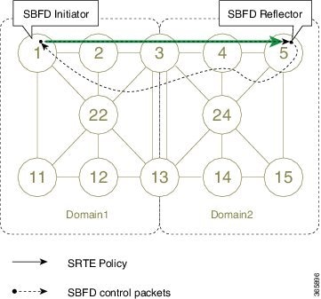
The following figure represents the roles of the SBFD initiator and reflector.

Figure 2. SBFD Initiator and Reflector

The initiator is an SBFD session on a network node that performs a continuity test to a remote entity by sending SBFD packets. The initiator injects the SBFD packets into the segment-routing traffic-engineering (SRTE) policy. The initiator triggers the SBFD session and maintains the BFD state and client context.

The reflector is an SBFD session on a network node that listens for incoming SBFD control packets to local entities and generates response SBFD control packets. The reflector is stateless and only reflects the SBFD packets back to the initiator.

A node can be both an initiator and a reflector, if you want to configure different SBFD sessions.

For SR-TE, SBFD control packets are label switched in forward and reverse direction. For SBFD, the tail-end node is the reflector node; other nodes cannot be a reflector. When using SBFD with SR-TE, if the forward and return directions are label-switched paths, SBFD need not be configured on the reflector node.

Discriminators

The BFD control packet carries 32-bit discriminators (local and remote) to demultiplex BFD sessions. SBFD requires globally unique SBFD discriminators that are known by the initiator.

The SBFD control packets contain the discriminator of the initiator, which is created dynamically, and the discriminator of the reflector, which is configured as a local discriminator on the reflector.

Configure the SBFD Reflector

To ensure the SBFD packet arrives on the intended reflector, each reflector has at least one globally unique discriminator. Globally unique discriminators of the reflector are known by the initiator before the session starts. An SBFD reflector only accepts BFD control packets where "Your Discriminator" is the reflector discriminator.

This task explains how to configure local discriminators on the reflector.

Before you begin

Enable mpls oam on the reflector to install a routing information base (RIB) entry for 127.0.0.0/8.


Router_5# configure
Router_5(config)# mpls oam
Router_5(config-oam)#

SUMMARY STEPS

  1. configure
  2. sbfd
  3. local-discriminator { ipv4-address | 32-bit-value | dynamic | interface interface}
  4. commit

DETAILED STEPS

  Command or Action Purpose

Step 1

configure

Example:

RP/0/RP0/CPU0:router# configure

Enters XR Config mode.

Step 2

sbfd

Example:

Router_5(config)# sbfd

Enters SBFD configuration mode.

Step 3

local-discriminator { ipv4-address | 32-bit-value | dynamic | interface interface}

Example:

Router_5(config-sbfd)# local-discriminator 10.1.1.5
Router_5(config-sbfd)# local-discriminator 987654321
Router_5(config-sbfd)# local-discriminator dynamic 
Router_5(config-sbfd)# local-discriminator interface Loopback0

Configures the local discriminator. You can configure multiple local discriminators.

Step 4

commit

Verify the local discriminator configuration.

Example

Router_5# show bfd target-identifier local 

Local Target Identifier Table
-----------------------------
Discr       Discr Src   VRF       Status   Flags
                        Name
-----       ---------   -------   -------- --------
16843013    Local       default   enable   -----ia-  
987654321   Local       default   enable   ----v---  
2147483649  Local       default   enable   -------d  

Legend: TID - Target Identifier
        a   - IP Address mode  
        d   - Dynamic mode     
        i   - Interface mode   
        v   - Explicit Value mode

What to do next

Configure the SBFD initiator.

Configure the SBFD Initiator

Perform the following configurations on the SBFD initiator.

Enable Line Cards to Host BFD Sessions

The SBFD initiator sessions are hosted by the line card CPU.

This task explains how to enable line cards to host BFD sessions.

SUMMARY STEPS

  1. configure
  2. bfd
  3. multipath include location node-id

DETAILED STEPS

  Command or Action Purpose

Step 1

configure

Example:

RP/0/RP0/CPU0:router# configure

Enters XR Config mode.

Step 2

bfd

Example:

Router_1(config)# bfd

Enters BFD configuration mode.

Step 3

multipath include location node-id

Example:

Router_1(config-bfd)# multipath include location 0/1/CPU0
Router_1(config-bfd)# multipath include location 0/2/CPU0
Router_1(config-bfd)# multipath include location 0/3/CPU0

Configures BFD multiple path on specific line card. Any of the configured line cards can be instructed to host a BFD session.

What to do next

Map a destination address to a remote discriminator.

Map a Destination Address to a Remote Discriminator

The SBFD initiator uses a Remote Target Identifier (RTI) table to map a destination address (Target ID) to a remote discriminator.

This task explains how to map a destination address to a remote discriminator.

SUMMARY STEPS

  1. configure
  2. sbfd
  3. remote-target ipv4 ipv4-address
  4. remote-discriminator remote-discriminator

DETAILED STEPS

  Command or Action Purpose

Step 1

configure

Example:

RP/0/RP0/CPU0:router# configure

Enters XR Config mode.

Step 2

sbfd

Example:

Router_1(config)# sbfd

Enters SBFD configuration mode.

Step 3

remote-target ipv4 ipv4-address

Example:

Router_1(config-sbfd)# remote-target ipv4 10.1.1.5

Configures the remote target.

Step 4

remote-discriminator remote-discriminator

Example:

Router_1(config-sbfd-nnnn)# remote-discriminator 16843013

Maps the destination address (Target ID) to a remote discriminator.

Verify the remote discriminator configuration.

Example

Router_1# show bfd target-identifier remote 

Remote Target Identifier Table
------------------------------
Discr       Discr Src   VRF        TID Type   Status
            Target ID   Name
------      ---------   -------    --------   ------
16843013    Remote      default    ipv4       enable    
            10.1.1.5                                 

Legend: TID - Target Identifier


What to do next

Enable SBFD on an SR-TE policy.

Enable Seamless BFD Under an SR-TE Policy or SR-ODN Color Template

This example shows how to enable SBFD on an SR-TE policy or an SR on-demand (SR-ODN) color template.


Note


Do not use BFD with disjoint paths. The reverse path might not be disjoint, causing a single link failure to bring down BFD sessions on both the disjoint paths.
Enable BFD
  • Use the bfd command in SR-TE policy configuration mode to enable BFD and enters BFD configuration mode.

    Router(config)# segment-routing traffic-eng 
    Router(config-sr-te)# policy POLICY1 
    Router(config-sr-te-policy)# bfd
    Router(config-sr-te-policy-bfd)#


    Use the bfd command in SR-ODN configuration mode to enable BFD and enters BFD configuration mode.

    Router(config)# segment-routing traffic-eng
    Router(config-sr-te)# on-demand color 10
    Router(config-sr-te-color)# bfd
    Router(config-sr-te-color-bfd)#
    
    
Configure BFD Options
  • Use the minimum-interval milliseconds command to set the interval between sending BFD hello packets to the neighbor. The range is from 15 to 200. The default is 15.

    Router(config-sr-te-policy-bfd)# minimum-interval 50
    
    
  • Use the multiplier multiplier command to set the number of times a packet is missed before BFD declares the neighbor down. The range is from 2 to 10. The default is 3.

    Router(config-sr-te-policy-bfd)# multiplier 2
    
    
  • Use the invalidation-action {down | none} command to set the action to be taken when BFD session is invalidated.

    • down : LSP can only be operationally up if the BFD session is up

    • none : BFD session state does not affect LSP state, use for diagnostic purposes

    Router(config-sr-te-policy-bfd)# invalidation-action down
    
    
  • (SR-TE policy only) Use the reverse-path binding-label label command to specify BFD packets return to head-end by using a binding label.

    By default, the S-BFD return path (from tail-end to head-end) is via IPv4. You can use a reverse binding label so that the packet arrives at the tail-end with the reverse binding label as the top label. This label is meant to point to a policy that will take the BFD packets back to the head-end. The reverse binding label is configured per-policy.

    Note that when MPLS return path is used, BFD uses echo mode packets, which means the tail-end’s BFD reflector does not process BFD packets at all.

    The MPLS label value at the tail-end and the head-end must be synchronized by the operator or controller. Because the tail-end binding label should remain constant, configure it as an explicit BSID, rather than dynamically allocated.

    Router(config-sr-te-policy-bfd)# reverse-path binding-label 24036
    
    
  • Use the logging session-state-change command to log when the state of the session changes

    Router(config-sr-te-policy-bfd)# logging session-state-change 
    
    
Examples

This example shows how to enable SBFD on an SR-TE policy.

Router(config)# segment-routing traffic-eng 
Router(config-sr-te)# policy POLICY1 
Router(config-sr-te-policy)# bfd
Router(config-sr-te-policy-bfd)# invalidation-action down
Router(config-sr-te-policy-bfd)# minimum-interval 50
Router(config-sr-te-policy-bfd)# multiplier 2
Router(config-sr-te-policy-bfd)# reverse-path binding-label 24036
Router(config-sr-te-policy-bfd)# logging session-state-change 


segment-routing
 traffic-eng
  policy POLICY1
   bfd
    minimum-interval 50
    multiplier 2
    invalidation-action down
    reverse-path
     binding-label 24036
    !
    logging
     session-state-change
    !
   !
  !
 !
!

This example shows how to enable SBFD on an SR-ODN color.

Router(config)# segment-routing traffic-eng 
Router(config-sr-te)# on-demand color 10
Router(config-sr-te-color)# bfd
Router(config-sr-te-color-bfd)# minimum-interval 50
Router(config-sr-te-color-bfd)# multiplier 2
Router(config-sr-te-color-bfd)# logging session-state-change 
Router(config-sr-te-color-bfd)# invalidation-action down


segment-routing
 traffic-eng
  on-demand color 10
   bfd
    minimum-interval 50
    multiplier 2
    invalidation-action down
    logging
     session-state-change
    !
   !
  !
 !
!

SR-TE Reoptimization Timers

SR-TE path re-optimization occurs when the head-end determines that there is a more optimal path available than the one currently used. For example, in case of a failure along the SR-TE LSP path, the head-end could detect and revert to a more optimal path by triggering re-optimization.

Re-optimization can occur due to the following events:

  • The explicit path hops used by the primary SR-TE LSP explicit path are modified

  • The head-end determines the currently used path-option are invalid due to either a topology path disconnect, or a missing SID in the SID database that is specified in the explicit-path

  • A more favorable path-option (lower index) becomes available

For event-based re-optimization, you can specify various delay timers for path re-optimization. For example, you can specify how long to wait before switching to a reoptimized path

Additionally, you can configure a timer to specify how often to perform reoptimization of policies. You can also trigger an immediate reoptimization for a specific policy or for all policies.

SR-TE Reoptimization

To trigger an immediate SR-TE reoptimization, use the segment-routing traffic-eng reoptimization command in Exec mode:


Router# segment-routing traffic-eng reoptimization {all | name  policy}

Use the all option to trigger an immediate reoptimization for all policies. Use the name policy option to trigger an immediate reoptimization for a specific policy.

Configuring SR-TE Reoptimization Timers

Use these commands in SR-TE configuration mode to configure SR-TE reoptimization timers:

  • timers candidate-path cleanup-delay seconds —Specifies the delay before cleaning up candidate paths, in seconds. The range is from 0 (immediate clean-up) to 86400; the default value is 120

  • timers cleanup-delay seconds —Specifies the delay before cleaning up previous path, in seconds. The range is from 0 (immediate clean-up) to 300; the default value is 10.

  • timers init-verify-restart seconds —Specifies the delay for topology convergence after the topology starts populating due to a restart, in seconds. The range is from 10 to 10000; the default is 40.

  • timers init-verify-startup seconds —Specifies the delay for topology convergence after topology starts populating for due to startup, in seconds. The range is from 10 to 10000; the default is 300

  • timers init-verify-switchover seconds —Specifies the delay for topology convergence after topology starts populating due to a switchover, in seconds. The range is from 10 to 10000; the default is 60.

  • timers install-delay seconds —Specifies the delay before switching to a reoptimized path, in seconds. The range is from 0 (immediate installation of new path) to 300; the default is 10.

  • timers periodic-reoptimization seconds —Specifies how often to perform periodic reoptimization of policies, in seconds. The range is from 0 to 86400; the default is 600.

Example Configuration

Router(config)# segment-routing traffic-eng
Router(config-sr-te)# timers 
Router(config-sr-te-timers)# candidate-path cleanup-delay 600
Router(config-sr-te-timers)# cleanup-delay 60
Router(config-sr-te-timers)# init-verify-restart 120
Router(config-sr-te-timers)# init-verify-startup 600
Router(config-sr-te-timers)# init-verify-switchover 30
Router(config-sr-te-timers)# install-delay 60
Router(config-sr-te-timers)# periodic-reoptimization 3000

Running Config

segment-routing
 traffic-eng
  timers
   install-delay 60
   periodic-reoptimization 3000
   cleanup-delay 60
   candidate-path cleanup-delay 600
   init-verify-restart 120
   init-verify-startup 600
   init-verify-switchover 30
  !
 !
!