Set Up Cisco Enterprise NFVIS

This chapter provides provides information to unbox and configure Enterprise Network Compute System (ENCS) 5400 series platform devices to be accessed remotely over the WAN. You will provision a router VNF (Virtual Network Function) instance and further configure it to enable traffic flow from LAN to WAN.

This chapter covers the following use cases to set up the initial configuration:

  • Set up using console serial cable.

  • Set up using ethernet cable.

You should be able to complete the entire setup in 60 minutes.

Introduction to ENCS 5400 Platform Devices

Cisco Enterprise Network Compute System (ENCS) 5000 series is a family of compute appliances designed for a virtualized software-defined branch network architecture. ENCS is a purpose-built hybrid platform with a small infrastructure footprint that combines the functionality of a traditional router with a traditional server. It allows you to deploy network services, Virtual Network Functions (VNFs), within minutes. For more information on ENCS features and datasheet see, Cisco 5000 Series Enterprise Network Compute System.

This chapter introduces you to ENCS 5400 series devices and its key components. This series includes the following models:

  • ENCS 5406

  • ENCS 5408

  • ENCS 5412

Installation Prerequisites

As a prerequisite, ensure that you have the following before getting started on the setup of the device:

  • ENCS 5400 device with supporting power cables

  • One console serial cable or two ethernet cables of suitable length

  • Windows or Mac Laptop with Terminal software that supports serial port connections

  • One available LAN IP address (10.29.43.84) to access the ENCS device on the LAN at this address for administration purposes.

  • Subnet mask (255.255.255.0) and Gateway IP address (10.29.43.1) to manage the ENCS device on your LAN. Ask your local LAN administrator for your environment.

Components of ENCS 5400 Series

Hardware

Figure 1. Install hardware ports

1

Ethernet management port

Manage network hypervisor (NFVIS) IP/virtual serial consol access to VNF

2

NFVIS and VNF Management through copper or fiber WAN port

Physical port shared between NFVIS and VNF services

3

CIMC ethernet connection

CLI access to NFVIS through CIMC-KVM

4

CIMC serial connection

CLI access to NFVIS through CIMC

Figure 2. Front Panel of the Cisco 5400 ENCS

1.

Power on/off switch

2

Integrated LAN ports - optional PoE support is available for some models

3

VGA connector

4

USB port

5

Serial console port for CPU

6

Ethernet management port for CPU

7

Front panel Gigabit Ethernet ports

8

LEDs for front panel Gigabit Ethernet ports

9

Network Interface Module (NIM)

10

Drive bay 0

11

Drive bay 1

12

Ethernet management port for CIMC

13

Serial console port for CIMC

Cisco IMC

Cisco Integrated Management Controller (CIMC) is an out-of-band embedded management service that runs natively on the device. You can access Cisco IMC console either through serial console cable, or an ethernet cable. It supports multiple interfaces, including a web user interface, a command-line interface (CLI), and an XML API.

You can perform firmware upgrade, BIOS upgrade, install and upgrade operating system and so on from Cisco IMC. For more information see, CIMC Access Control.


Note


In this guide we will not be using Cisco IMC to complete the minimal setup.


NFVIS

Cisco Network Function Virtualization Infrastructure Software (NFVIS) is an operating system software for software-defined branch network virtualization deployments. NFVIS is the operating system for all ENCS series of devices. NFVIS is based on open source Kernel-based Virtual Machine (KVM) hypervisor.

NFVIS enables you to run one or more network services like router, firewall and so on as Virtual Machines (VMs) also known as Virtual Network Functions (VNFs) on a single hardware platform.

You can access NFVIS through:

  • Serial console port using a serial console cable, or

  • Dedicated NFVIS management ethernet port which gives you access to the web-based GUI console, or

  • Cisco IMC.

This chapter includes instructions to setup an ENCS device using the GUI console.

For more information on NFVIS see, Enterprise NFV Infrastructure Software.

VNFs

Virtual Network Functions (VNFs), is a collective term used to describe virtualized network services such as a virtual router, a virtual firewall, a virtual load balancer and so on. VNF is synonymous to Virtual Machine (VM).

Every ENCS device comes pre-installed with a virtual appliance image file of Cisco virtual Integrated Services Router (ISRv). This chapter describes how to use this image file to create a router VNF instance and then configure it to enable traffic on the LAN to flow towards the WAN.

Unpacking and Cabling ENCS 5400

Unpacking the Device

The device, accessory kit, publications, and any optional units may be shipped in more than one container. When you unpack the containers, check the packing list to ensure that you have received all the items on the list.

Only unpack the product when you are ready to install it. This will help prevent accidental damage.

Remove the ENCS device from the shipping box and rack it up as per the instructions in the box.

Cabling

The device will automatically power-on when you connect the power cable to the device. Configure NFVIS management IP address on the device, so that it can be managed remotely over the LAN.

You can configure NFVIS management IP address on the device using:

  • Serial console cable: Connect your laptop to the serial port on the device using a serial console cable and set up the NFVIS IP address. Also use the Ethernet cable to connect the device management Ethernet port to local management network and then access the device remotely for further configurations.

    To access the device over a dedicated management Ethernet port use the serial console cable to setup the device management IP address. You can then access the NFVIS portal using the configured device management IP address for the installation procedure.

    Connect one end of the serial console cable to the port labeled CONSOLE on the ENCS device and the other end to your laptop serial port or USB port.

    Figure 3. Serial Concole Cable connection
  • Ethernet cable: Connect your laptop to the management Ethernet port on the device using an Ethernet cable and set up the NFVIS IP address. To manage the device remotely over the management network, reconnect the management port to the local management network.

    Connect one end of the Ethernet cable to the MGMT CPU port on the ENCS device and the other end to your laptop Ethernet port or local switch.

    Figure 4. Ethernet Cable connection

Install NFVIS on ENCS 5400 Platforms

After unboxing and cabling the ENCS device:

  1. Set up the NFVIS management IP address to access the device remotely over LAN.

  2. Create a VNF instance using Cisco ISRv router on NFVIS web-based GUI console.

  3. Configure ISRv router to enable LAN to WAN connectivity.

  4. Validate LAN to WAN connectivity.

Access NFVIS

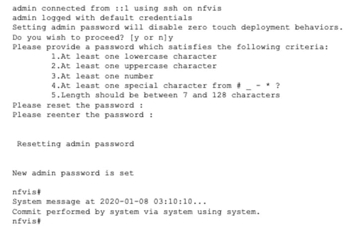
  1. For initial NFVIS login, the default username is admin and the default password is Admin123#.

    
    NFVIS Version: 3.12.3
    
    Copyright (c) 2015-2020 by Cisco Systems, Inc.
    Cisco, Cisco Systems, and Cisco Systems logo are registered trademarks of Cisco
    Systems, Inc. and/or its affiliates in the U.S. and certain other countries.
    
    The copyrights to certain works contained in this software are owned by other
    third parties and used and distributed under third party license agreements.
    Certain components of this software are licensed under the GNU GPL 2.0, GPL 3.0,
    LGPL 2.1, LGPL 3.0 and AGPL 3.0.
    
  2. Immediately after the initial login, the system prompts you to change the default password. All other operations are blocked until default password is changed.

    You must adhere to the following rules to create a strong password:

    • Must contain at least one upper case and one lower case letter.

    • Must contain at least one number and one special character (# _ - * ?).

    • Must contain seven characters or greater. Length should be between 7 and 128 characters.

  3. After you change the password you will be at the nfvis prompt.

  4. After you login to NFVIS, you can see the information about NFVIS version. You can then decide if you want to install or upgrade to a newer version.

Configure the Device Management IP Address

  1. Configure the device management IP address.

    
    configure terminal
    system settings mgmt ip address 10.29.43.84 255.255.255.0
    bridges bridge wan-br no dhcp
    bridges bridge wan2-br no dhcp
    system settings default-gw 10.29.43.1
    commit
    end
    
  2. The device management IP address is now set to 10.29.43.84 and you can access NFVIS remotely at this address.

  3. Use the show system settings-native command to confirm the settings and display the current values.

  4. To logout from the system enter Exit.

Access NFVIS Portal

To access NFVIS portal:

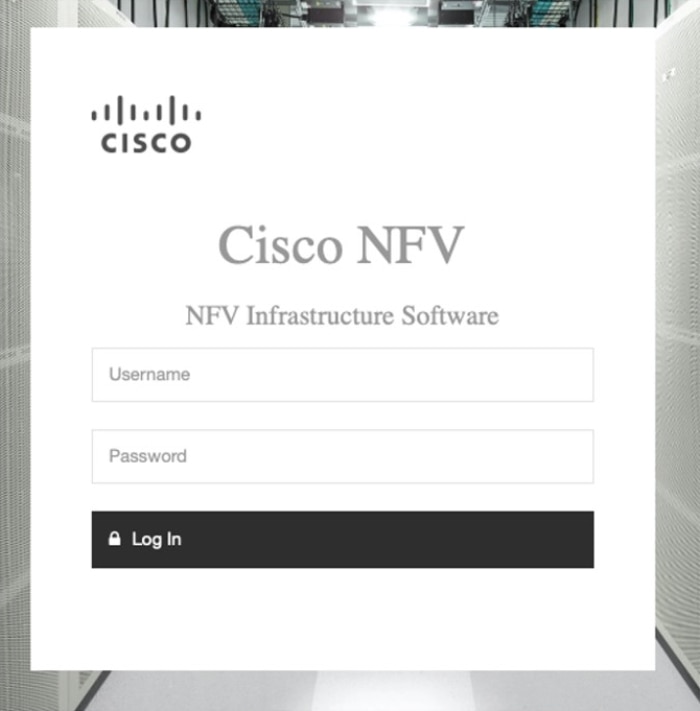
  1. Connect your laptop to the local ethernet management network. Enter https://10.29.43.84 in your web browser's address bar. We recommend that you use Google Chrome.

  2. To login to NFVIS portal, the username is admin and password is the new generated password. You will see the NFVIS dashboard which provides a summary of activities on the device.

Create and Deploy a Virtual Router

To deploy a virtual router on a factory shipped ENCS 5400 device:

  1. Chose VM Life Cycle > Image Repository from the navigation tree on the left of the interface. Here you will see all the previously uploaded images in the device.

    For a factory shipped ENCS 5400 device, in Images, the only available image is isrv.tar.gz and in Profiles, you can see isrv-mini, isrv-small and isrv-medium or C8000V-mini, C8000V-small and C8000V-medium.

    In Images you can see information about the available images and make a note of the version for an upgrade if required. The ACTIVE state of the image indicates that the image is registered and ready for deployment.

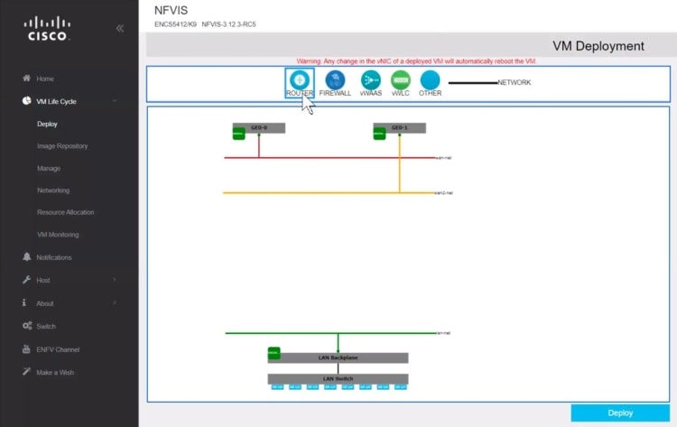
  2. Chose VM Life Cycle > Deploy.

    You can a catalog of various VNFs at the top of the page. The default configuration of the device at the center of the page has LAN, WAN, and WAN2 networks.

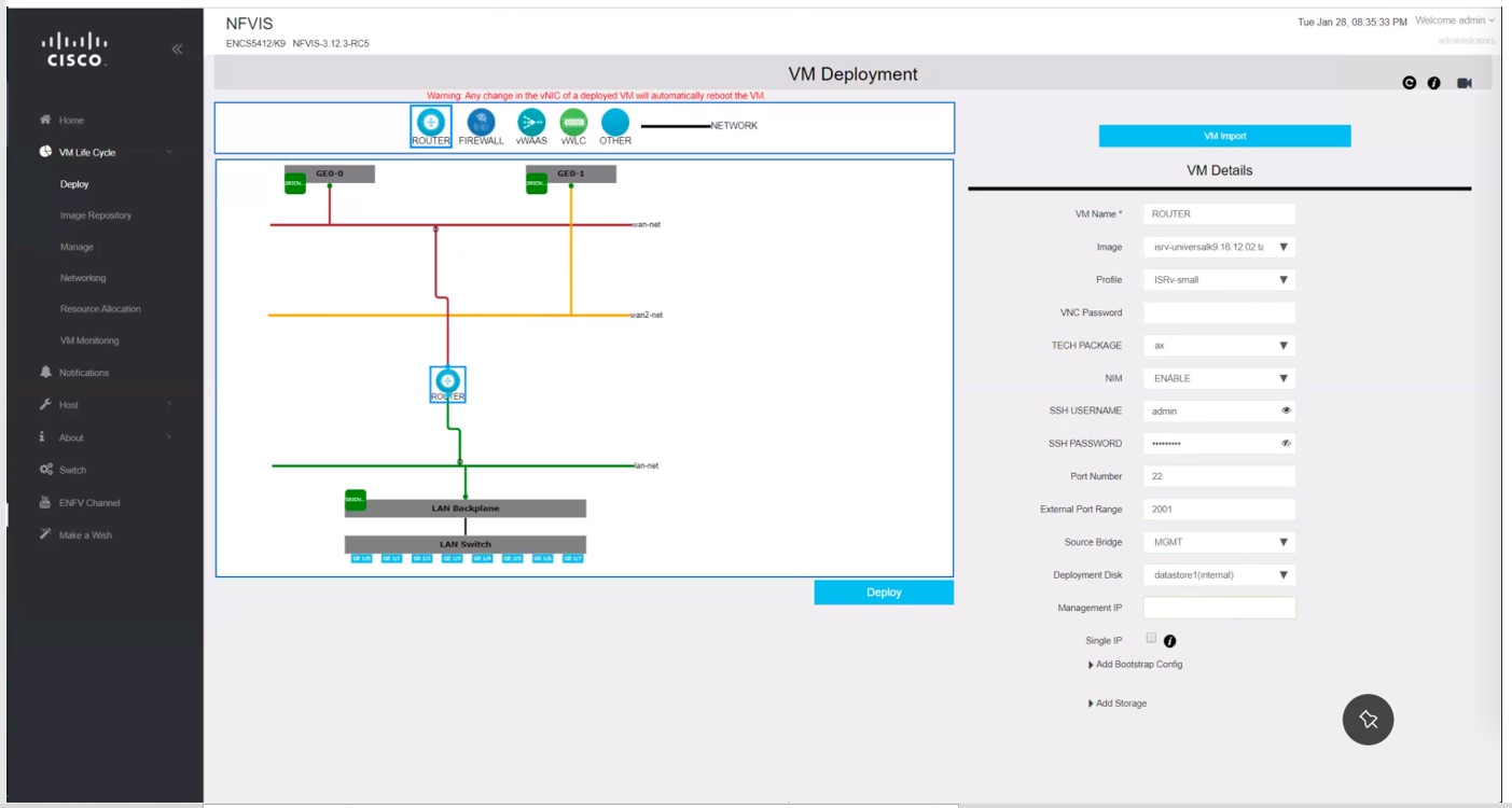
  3. To create a router instance with a LAN and WAN connection click and drag ROUTER to the center of the page. To configure a connection to the WAN, click ROUTER on the page and drag it to the wan-net line.

    Select the connected line to view the details. In the vNIC details pane you will see that the interface GigabitEthernet2 is associated with the WAN (wan-net). Record this interface name to use the same name to configure the WAN subnet later.

    To configure a LAN connection, click ROUTER again and this time drag it to the lan-net line.

    Select the connected line to view the details. In the vNIC details pane you will see that interface GigabitEthernet3 is associated with the LAN (lan-net). Record this interface name to use this same name to configure the local subnet later.

  4. Click on ROUTER and enter the VM Details:

    
    Profile: isrv-small
    SSH USERNAME: admin
    SSH PASSWORD: time44Fun
    Port Number: 22
    External Port Range: 2001
    Source Bridge: MGMT
    Deployment Disk: datastore1(internal)
    

    These values indicate that the VM uses isrv-small profile which is has 2 CPUs, 4 GB of memory, and 8 GB of disk space. You can remotely login to this VM through SSH with the credentials specified in SSH USERNAME and SSH PASSWORD. The Port Number and External Port Range values maps port 2001 on the management network IP address to port number 22 in the VM, as required for SSH connectivity into the VM over the management network (Source Bridge = MGMT). This VNF will be stored in the default datastore named as datastore1(internal).

  5. Click Deploy to deploy the VM and see the progress of the deployment on the right side of the page. A successful deployment is indicated through a pop-up message on the corner of the page.

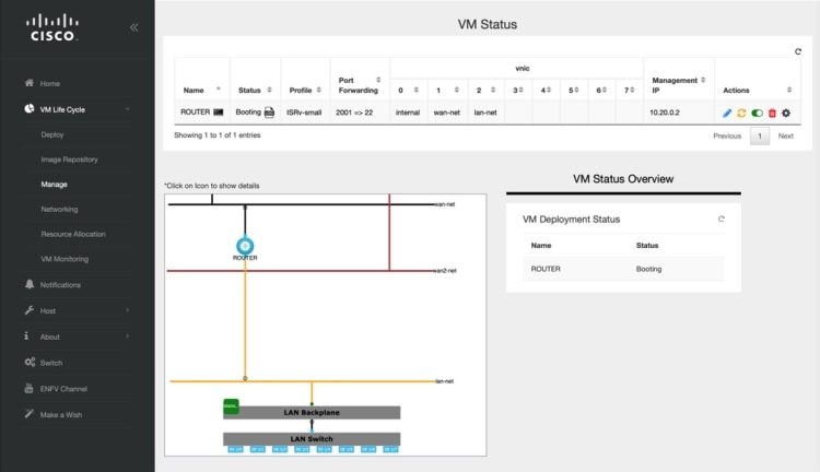
  6. To monitor the progress of the router VNF booting, chose VM Life Cycle > Manage.

    The status of the deployment is displayed in VM Status Overview. Click on the refresh button to get the latest status.

  7. When the router VNF is ready you can see all the data related to it.

You have now completed the creation and deployment of ISRv router VNF instance.

LAN to WAN Connectivity

After successfully creating and deploying the virtual router, configure the virtual router to enable traffic flow from the LAN network to the WAN. The following image shows the LAN to WAN connectivity through a virtual router:

Figure 5. LAN and WAN Connection Through Virtual Router

The traffic flow from the laptop to WAN is through the physical 8-port embedded switch in ENCS and the OVS virtual switch lan-net. The laptop is connected to port GE1/0 on the embedded 8-port switch with an Ethernet cable. The laptop has 10.0.0.3 as static IP address, 10.0.0.1 as gateway IP address and subnet mask as 255.255.255.0.

By default, GE1/0 port is configured to be in access mode with VLAN tag 1, the internal virtual lan-net OVS switch is in trunk mode and the virtual router is configured to accept the untagged traffic.

The gateway IP address 10.0.0.1 is configured on the virtual router. The virtual router is connected to the external WAN port that enables traffic to flow to and from the WAN.

During the router VNF deployment, you need to set external port, and source-bridge pointing out same bridge that is used to provide access to the system, such as wan-br or lan-br. Now you should be able to SSH to this router VNF from your laptop on the management network. To login:


ssh admin@10.29.43.84:2001

Use the same password as what you had specified while creating the VNF instance:


time44Fun

Configure the LAN facing interface of the router to 10.0.0.1/24 subnet:


interface GigabitEthernet3
ip address 10.0.0.1 255.255.255.0

Configure the WAN side of the router:


interface GigabitEthernet2
ip address 172.16.1.10 255.255.255.0

Set the default route:


ip route 0.0.0.0 0.0.0.0 172.16.1.1

Now from the laptop you should be able to reach any destination on the WAN.

You have now successfully deployed a virtual router on a factory shipped ENCS 5400 device. For further configurations, see Cisco Enterprise Network Function Virtualization Infrastructure Software Configuration Guide.