Set Up and Configure Cisco Catalyst SD-WAN Manager


Note


To achieve simplification and consistency, the Cisco SD-WAN solution has been rebranded as Cisco Catalyst SD-WAN. In addition, from Cisco IOS XE SD-WAN Release 17.12.1a and Cisco Catalyst SD-WAN Release 20.12.1, the following component changes are applicable: Cisco vManage to Cisco Catalyst SD-WAN Manager, Cisco vAnalytics to Cisco Catalyst SD-WAN Analytics, Cisco vBond to Cisco Catalyst SD-WAN Validator, Cisco vSmart to Cisco Catalyst SD-WAN Controller, and Cisco Controllers to Cisco Catalyst SD-WAN Control Components. See the latest Release Notes for a comprehensive list of all the component brand name changes. While we transition to the new names, some inconsistencies might be present in the documentation set because of a phased approach to the user interface updates of the software product.

Configure the Network

The topics in this section describe how to configure your network.

Bring-Up Sequence of Events

The bring-up process for edge devices—which includes authenticating and validating all the devices and establishing a functional overlay network—occurs with only minimal user input. From a conceptual point of view, the bring-up process can be divided into two parts, one that requires user input and one that happens automatically:

  1. In the first part, you design the network, create virtual machine (VM) instances for cloud routers, and install and boot hardware routers. Then, in Cisco SD-WAN Manager, you add the routers to the network and create configurations for each router. This process is described in the Summary of the User Portion of the Bring-Up Sequence.

  2. The second part of the bring-up process occurs automatically, orchestrated by the Cisco Catalyst SD-WAN software.​ As routers join the overlay network, they validate and authenticate themselves automatically, and they establish secure communication channels between each other. For Cisco SD-WAN Validators and Cisco SD-WAN Controllers, a network administrator must download the necessary authentication-related files from Cisco SD-WAN Manager, and then these Cisco SD-WAN Controllers and Cisco SD-WAN Validators automatically receive their configurations from Cisco SD-WAN Manager. After Cisco hardware routers start, they are authenticated on the network and receive their configurations automatically from Cisco SD-WAN Manager through a process called zero-touch provisioning (ZTP). This process is described in the Automatic Portions of the Bring-Up Sequence.

    The end result of this two-part process is an operational overlay network.

    This topic describes the sequence of events that occurs during the bring-up process, starting with the user portion and then explaining how automatic authentication and device validation occur.

Sequence of Events of the Bring-Up Process

From a functional point of view, the task of bringing up the routers in the overlay network occurs in the following sequence:
Figure 1. Bring-Up Sequence of Events
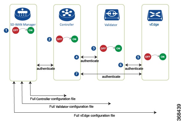
  1. The Cisco SD-WAN Manager software starts on a server in the data center.

  2. The Cisco SD-WAN Validator starts on a server in the DMZ.

  3. The Cisco SD-WAN Controller starts on a server in the data center.

  4. Cisco SD-WAN Manager and the Cisco SD-WAN Validator authenticate each other, Cisco SD-WAN Manager and the Cisco SD-WAN Controller authenticate each other, and the Cisco SD-WAN Controller and the Cisco SD-WAN Validator securely authenticate each other.

  5. Cisco SD-WAN Manager sends configurations to the Cisco SD-WAN Controller and the Cisco SD-WAN Validator.

  6. The routers start in the network.

  7. The routers authenticate themselves with the Cisco SD-WAN Validator.

  8. The routers authenticate themselves with Cisco SD-WAN Manager.

  9. The routers authenticate themselves with the Cisco SD-WAN Controller.

  10. Cisco SD-WAN Manager sends configurations to the routers.

Before you start the bring-up process, note the following:

  • To provide the highest level of security, only authenticated and authorized routers can access and participation in the Cisco Catalyst SD-WAN overlay network. To this end, the Cisco SD-WAN Controller performs automatic authentication on all the routers before they can send data traffic over the network.

  • After the routers are authenticated, data traffic flows, regardless of whether the routers are in a private address space (behind a NAT gateway) or in a public address space.

To bring up the hardware and software components in a Cisco Catalyst SD-WAN overlay network, a transport network (also called a transport cloud), which connects all the routers and other network hardware components, must be available. Typically, these components are in data centers and branch offices. The only purpose of the transport network is to connect all the network devices in the domain. The Cisco Catalyst SD-WAN solution is agnostic with regards to the transport network, and, therefore, can be any type, including the internet, Multiprotocol Label Switching (MPLS), Layer 2 switching, Layer 3 routing, and Long-Term Evolution (LTE), or any mixture of transports.

For hardware routers, you can use the Cisco Catalyst SD-WAN zero-touch provisioning (ZTP) SaaS to bring up the routers. For more information on automatic process to bring-up hardware in the overlay network, see Prepare Routers for ZTP.

Summary of the User Portion of the Bring-Up Sequence

In a general sense, what you do to bring up the Cisco Catalyst SD-WAN overlay network is what you would do to bring up any network—you plan out the network, create device configurations, and then deploy the network hardware and software components. These components include all the Cisco IOS XE Catalyst SD-WAN devices, all the traditional routers that participate in the overlay network, and all the network devices that provide shared services across the overlay network, such as firewalls, load balancers, and identity provider (IdP) systems.​

The following table summarizes the steps for the user portion of the Cisco Catalyst SD-WAN overlay network bring-up sequence. The details of each step are provided in the links listed in the Procedure column. While you can bring up the Cisco IOS XE Catalyst SD-WAN devices in any order, we recommend that you deploy them in the order listed in the table, which is the functional order in which the devices verify and authenticate themselves.

Table 1. Workflow for the Bring-Up Sequence

Workflow

Procedure

1

Plan out your overlay network.

2

Deploy the Cisco IOS XE Catalyst SD-WAN devices in the overlay network:

  1. For the cloud routers, create a VM instance, either on an AWS server, an ESXi, or a KVM hypervisor.

  2. From Cisco SD-WAN Manager, send the serial numbers of all Cisco IOS XE Catalyst SD-WAN devices to the Cisco SD-WAN Controllers and Cisco SD-WAN Validators in the overlay network.

  3. Create a full configuration for the Cisco IOS XE Catalyst SD-WAN devices by creating configuration templates on Cisco SD-WAN Manager. When Cisco SD-WAN Manager discovers a device in the overlay network, it pushes the appropriate configuration template to the device.

System and Interfaces Overview

Setting up the basic system-wide functionality of network devices is a simple and straightforward process. Basic parameters include defining host properties, such as name and IP address; setting time properties, including NTP; setting up user access to the devices; and defining system log (syslog) parameters.

In addition, the Cisco Catalyst SD-WAN software provides a number of management interfaces for accessing the Cisco Catalyst SD-WAN devices in the overlay network.

Host Properties

All devices have basic system-wide properties that specify information that the Cisco Catalyst SD-WAN software uses to construct a view of the network topology. Each device has a system IP address that provides a fixed location of the device in the overlay network. This address, which functions the same way as a router ID on a router, is independent of any of the interfaces and interface IP addresses on the device. The system IP address is one of the four components of the Transport Location (TLOC) property of each device.

A second host property that must be set on all devices is the IP address of the Cisco SD-WAN Validator for the network domain, or a Domain Name System (DNS) name that resolves to one or more IP addresses for Cisco SD-WAN Validators. A Cisco SD-WAN Validator automatically orchestrates the process of bringing up the overlay network, admitting a new device into the overlay, and providing the introductions that allow the device and Cisco SD-WAN Controllers to locate each other.

Two other system-wide host properties are required on all devices, except for the Cisco SD-WAN Validators, to allow the Cisco Catalyst SD-WAN software to construct a view of the topology—the domain identifier and the site identifier.

To configure the host properties, see Cisco Catalyst SD-WAN Overlay Network Bring-Up Process.

Time and NTP

The Cisco Catalyst SD-WAN software implements the Network Time Protocol (NTP) to synchronize and coordinate time distribution across the Cisco Catalyst SD-WAN overlay network. NTP uses a intersection algorithm to select the applicable time servers and avoid issues caused due to network latency. The servers can also redistribute reference time using local routing algorithms and time daemons. NTP is defined in RFC 5905, Network Time Protocol Version 4: Protocol and Algorithms Specification.

User Authentication and Access with AAA, RADIUS, and TACACS+

The Cisco Catalyst SD-WAN software uses Authentication, Authorization, and Accounting (AAA) to provide security for the devices on a network. AAA, in combination with RADIUS and Terminal Access Controller Access-Control System (TACACS+) user authentication, controls which users are allowed access to devices, and what operations they are authorized to perform after they are logged in or connected to the devices.

Authentication refers to the process by which users trying to access the devices are authenticated. To access devices, users log in with a username and a password. The local device can authenticate users. Alternatively, authentication can be performed by a remote device, either a RADIUS server or a TACACS+ server, or both in a sequence.

Authorization determines whether a user is authorized to perform a given activity on a device. In the Cisco Catalyst SD-WAN software, authorization is implemented using role-based access. Access is based on groups that are configured on the devices. A user can be a member of one or more groups. User-defined groups are considered when performing authorization, that is, the Cisco Catalyst SD-WAN software uses group names received from RADIUS or TACACS+ servers to check the authorization level of a user. Each group is assigned privileges that authorize the group members to perform specific functions on the corresponding device. These privileges correspond to specific hierarchies of the configuration commands and the corresponding hierarchies of operational commands that members of the group are allowed to view or modify.

Beginning in Cisco IOS XE Catalyst SD-WAN Release 17.5.1a, accounting generates a record of commands that a user executes on a device. Accounting is performed by a TACACS+ server.

For more information, see Role-Based Access with AAA.

Authentication for WANs and WLANs

For wired networks (WANs), Cisco Catalyst SD-WAN devices can run IEEE 802.1X software to prevent unauthorized network devices from gaining access to the WAN. IEEE 802.1X is a port-based network access control (PNAC) protocol that uses a client–server mechanism to provide authentication for devices wishing to connect to the network.

IEEE 802.1X authentication requires three components:

  • Requester: Client device, such as a laptop, that requests access to the Wide-Area Network (WAN). In the Cisco Catalyst SD-WAN overlay network, a supplicant is any service-side device that is running 802.1X-compliant software. These devices send network access requests to the router.

  • Authenticator: A network device that provides a barrier to the WAN. In the overlay network, you can configure an interface device to act as an 802.1X authenticator. The device supports both controlled and uncontrolled ports. For controlled ports, the Cisco Catalyst SD-WAN device acts as an 802.1X port access entity (PAE), allowing authorized network traffic and preventing unauthorized network traffic ingressing to and egressing from the controlled port. For uncontrolled ports, Cisco Catalyst SD-WAN, acting as an 802.1X PAE, transmits and receives Extensible Authentication Protocol over IEEE 802 (EAP over LAN, or EAPOL) frames.

  • Authentication server: Host that is running authentication software that validates and authenticates requesters that want to connect to the WAN. In the overlay network, this host is an external RADIUS server. This RADIUS server authenticates each client connected to the 802.1X port interface Cisco Catalyst SD-WAN device and assigns the interface to a virtual LAN (VLAN) before the client is allowed to access any of the services offered by the router or by the LAN.

For wireless LANs (WLANs), routers can run IEEE 802.11i to prevent unauthorized network devices from gaining access to the WLANs. IEEE 802.11i implements Wi-Fi Protected Access (WPA) and Wi-Fi Protected Access II (WPA2) to provide authentication and encryption for devices that want to connect to a WLAN. WPA authenticates individual users on the WLAN using a username and a password. WPA uses the Temporal Key Integrity Protocol (TKIP), which is based on the RC4 cipher. WPA2 implements the NIST FIPS 140-2–compliant AES encryption algorithm along with IEEE 802.1X-based authentication, to enhance user access security over WPA. WPA2 uses the Counter Mode Cipher Block Chaining Message Authentication Code Protocol (CCMP), which is based on the AES cipher. Authentication is done by either using preshared keys or through RADIUS authentication.

Network Segmentation

The Layer 3 network segmentation in Cisco Catalyst SD-WAN is achieved through VRFs on Cisco IOS XE Catalyst SD-WAN devices. When you configure the network segmentation on a Cisco IOS XE Catalyst SD-WAN device using Cisco SD-WAN Manager, the system automatically maps the VPN configurations to VRF configurations.

Network Interfaces

In the Cisco Catalyst SD-WAN overlay network design, interfaces are associated with VPNs that translate to VRFs. The interfaces that participate in a VPN are configured and enabled in that VPN. Each interface can be present only in a single VPN.


Note


Cisco IOS XE Catalyst SD-WAN devices use VRFs in place of VPNs. When you complete the configuration on Cisco SD-WAN Manager, the system automatically maps the VPN configurations to VRF configurations.


The overlay network has the following types of VPNs/VRFs:

  • VPN 0: Transport VPN, that carries control traffic using the configured WAN transport interfaces. Initially, VPN 0 contains all the interfaces on a device except for the management interface, and all the interfaces are disabled. This is the global VRF on Cisco IOS XE Catalyst SD-WAN software.

  • VPN 512: Management VPN, that carries out-of-band network management traffic among the Cisco Catalyst SD-WAN devices in the overlay network. The interface used for management traffic resides in VPN 512. By default, VPN 512 is configured and enabled on all Cisco Catalyst SD-WAN devices. For controller devices, by default, VPN 512 is not configured. On Cisco IOS XE Catalyst SD-WAN devices, the management VPN is converted to VRF Mgmt-Intf.

For each network interface, you can configure a number of interface-specific properties, such as DHCP clients and servers, VRRP, interface MTU and speed, and Point-to-Point Protocol over Ethernet (PPPoE). At a high level, for an interface to be operational, you must configure an IP address for the interface and mark it as operational (no shutdown). In practice, you always configure additional parameters for each interface.

Management and Monitoring Options

There are various ways in which you can manage and monitor a router. Management interfaces provide access to devices in the Cisco Catalyst SD-WAN overlay network, allowing you to collect information from the devices in an out-of-band fashion and to perform operations on the devices, such as configuring and rebooting them.

The following management interfaces are available:

  • CLI

  • IP Flow Information Export (IPFIX)

  • RESTful API

  • SNMP

  • System logging (syslog) messages

  • Cisco SD-WAN Manager

CLI

You can access a CLI on each device, and from the CLI, you configure overlay network features on the local device and gather operational status and information regarding that device. Using an available CLI, we strongly recommend that you configure and monitor all the Cisco Catalyst SD-WAN network devices from Cisco SD-WAN Manager, which provides views of network-wide operations and device status, including detailed operational and status data. In addition, Cisco SD-WAN Manager provides straightforward tools for bringing up and configuring overlay network devices, including bulk operations for setting up multiple devices simultaneously.

You can access the CLI by establishing an SSH session to a Cisco Catalyst SD-WAN device.

For a Cisco Catalyst SD-WAN device that is being managed by Cisco SD-WAN Manager, if you create or modify the configuration from the CLI, the changes are overwritten by the configuration that is stored in the Cisco SD-WAN Manager configuration database.

IPFIX

The IP Flow Information Export (IPFIX) protocol, also called cflowd, is a tool for monitoring the traffic flowing through Cisco Catalyst SD-WAN devices in the overlay network and exporting information about the traffic to a flow collector. The exported information is sent in template reports, that contain both information about the flow and the data extracted from the IP headers of the packets in the flow.

Cisco Catalyst SD-WAN cflowd performs 1:1 traffic sampling. Information about all the flows is aggregated in the cflowd records; flows are not sampled.


Note


Cisco Catalyst SD-WAN devices do not cache any of the records that are exported to a collector.


The Cisco Catalyst SD-WAN cflowd software implements cflowd Version 10, as specified in RFC 7011 and RFC 7012.

For a list of elements exported by IPFIX, see Traffic Flow Monitoring with Cflowd.

To enable the collection of traffic flow information, you must create data policies that identify the traffic of interest, and then direct that traffic to a cflowd collector. For more information, see Traffic Flow Monitoring with Cflowd.

You can also enable cflowd visibility directly on Cisco Catalyst SD-WAN devices without configuring a data policy, so that you can perform traffic flow monitoring on the traffic coming to the device from all the VPNs in the LAN. You can then monitor the traffic from Cisco SD-WAN Manager or from the device's CLI.

RESTful API

The Cisco Catalyst SD-WAN software provides a RESTful API, which is a programmatic interface for controlling, configuring, and monitoring the Cisco Catalyst SD-WAN devices in an overlay network. You can access the RESTful API through Cisco SD-WAN Manager.

The Cisco Catalyst SD-WAN RESTful API calls expose the functionality of the Cisco Catalyst SD-WAN software and hardware to an application program. Such functionality includes the normal operations you perform to maintain the devices and the overlay network itself.

SNMP

The Simple Network Management Protocol (SNMP) allows you to manage all the Cisco Catalyst SD-WAN devices in the overlay network. The Cisco Catalyst SD-WAN software supports SNMP v2c.

You can configure basic SNMP properties—device name, location, contact, and community—that allow the device to be monitored by an SNMP Network Management System (NMS).

You can configure trap groups and SNMP servers to receive traps.

The object identifier (OID) for the internet port of the SNMP MIB is 1.3.6.1.

SNMP traps are asynchronous notifications that a Cisco Catalyst SD-WAN device sends to an SNMP management server. Traps notify the management server of events, whether normal or significant, that occur on the Cisco Catalyst SD-WAN device. By default, SNMP traps are not sent to an SNMP server. Note that for SNMPv3, the PDU type for notifications, is either SNMPv2c inform (InformRequest-PDU) or trap (Trapv2-PDU).

Syslog Messages

System logging operations use a mechanism that is similar to the UNIX syslog command to record system-wide, high-level operations that occur on the Cisco Catalyst SD-WAN devices in the overlay network. The log levels (priorities) of the messages are the same as those in standard UNIX commands, and you can configure the priority of the syslog messages that should be logged. Messages can be logged to files on the Cisco Catalyst SD-WAN device or to a remote host.

Cisco SD-WAN Manager

Cisco SD-WAN Manager is a centralized network management system that allows configuration and management of all the Cisco Catalyst SD-WAN devices in the overlay network, and provides a dashboard displaying the operations of the entire network and of individual devices in the network. Three or more Cisco SD-WAN Manager servers are consolidated into a Cisco SD-WAN Manager cluster to provide scalability and management support for up to 6,000 Cisco Catalyst SD-WAN devices, to distribute Cisco SD-WAN Manager functions across multiple devices, and to provide redundancy of network management operations.

Configure Single Sign-On Using Okta

Okta provides a secure identity management service that lets you connect any person with any application on any device using single sign-on (SSO).


Note


Beginning with Cisco vManage Release 20.3.1, Cisco SD-WAN Manager no longer supports MD5 or SHA-1. All x.509 certificates handled by Cisco SD-WAN Manager need to use at least SHA-256 or a higher encryption algorithm.


Perform the following procedures to configure SSO.

Enable an Identity Provider in Cisco SD-WAN Manager

To configure Okta SSO, use Cisco SD-WAN Manager to enable an identity provider and generate a Security Assertion Markup Language (SAML) metadata file.

From Cisco vManage Release 20.10.1, you can use Add New IDP Settings to configure up to three IdPs. For more information on integrating with multiple IdPs, see the chapter Configure Multiple IdPs.

  1. From the Cisco SD-WAN Manager menu, choose Administration > Settings.

  2. Click Identity Provider Settings and then click Edit.

  3. Click Enabled.

  4. Click Click here to download the SAML metadata and save the contents in a text file. This data is used for configuring Okta.

  5. From the metadata that is displayed, make a note of the following information that you need for configuring Okta with Cisco SD-WAN Manager:

    • Entity ID

    • Signing certificate

    • Encryption certificate

    • Logout URL

    • Login URL


    Note


    Administrators can set up SSO using a single Entity ID only. Cisco SD-WAN Manager doesn't support more than one Entity ID while setting up SSO.


  6. In the Upload Identity Provider Metadata section, click Select a File to upload the IdP metadata file.

  7. Click Save.

Configure SSO on the Okta Website


Note


This procedure involves a third-party website. The details are subject to change.


To configure SSO on the Okta website:

  1. Log in to the Okta website.


    Note


    Each IdP application gets a customized URL from Okta for logging in to the Okta website.


  2. Create a username using your email address.

  3. To add Cisco SD-WAN Manager as an SSO application, from the Cisco SD-WAN Manager menu, click Admin.

  4. Check the upper-left corner to ensure that it shows the Classic UI view on Okta.

  5. If it shows Developer Console, click the down triangle to choose the Classic UI.

  6. Click Add Application under Shortcuts to the right to go to the next window, and then click Create New Application on the pop-up window.

  7. Choose Web for the platform, and choose SAML 2.0 as the Sign on Method.

  8. Click Create.

  9. Enter a string as Application name.

  10. (Optional): Upload a logo, and then click Next.

  11. On the SAML Settings for Single sign on URL section, set the value to the samlLoginResponse URL from the downloaded metadata from Cisco SD-WAN Manager.

  12. Check the Use this for Recipient URL and Destination URL check box.

  13. Copy the entityID string and paste it in the Audience URI (SP Entity ID) field.

    The value can be an IP address or the name of the Cisco SD-WAN Manager site.

  14. For Default RelayState, leave empty.

  15. For Name ID format, choose EmailAddress.

  16. For Application username, choose Okta username.

  17. For Show Advanced Settings, enter the fields as indicated below.

    Table 2. Fields for Show Advanced Settings

    Component

    Value

    Configuration

    Response

    Signed

    Not applicable

    Assertion Signature

    Signed

    Not applicable

    Signature Algorithm

    RSA-SHA256

    Not applicable

    Digest Algorithm

    SHA256

    Not applicable

    Assertion Encryption

    Encrypted

    Not applicable

    Encryption Algorithm

    AES256-CBC

    Not applicable

    Key Transport Algorithm

    RSA-OAEP

    Not applicable

    Encryption Certificate

    Not applicable
    1. Copy the encryption certificate from the metadata you downloaded.

    2. Go to www.samltool.com and click X.509 CERTS, paste there. Click Format X.509 Certificate.

    3. Ensure to remove the last empty line and then save the output (X.509.cert with header) into a text file encryption.cer.

    4. Upload the file. Mozilla Firefox may not allow you to do the upload. Instead, you can use Google Chrome. You should see the certificate information after uploading to Okta.

    Enable Single Logout

    Ensure that this is checked.

    Single Logout URL

    Get from the metadata.

    Service provider Issuer

    Use the entityID from the metadata.

    Signature Certificate

    1. Obtain from the metadata. Format the signature certificate using www.samltool.com as described.

    2. Save to a file, for example, signing.cer and upload.

    Authentication context class

    X.509 Certificate

    Not applicable

    Honor Force Authentication

    Yes

    Not applicable

    SAML issuer ID string

    SAML issuer ID string

    Not applicable

    Attribute Statements

    Field: Name

    Value: Username

    Field: Name format (optional)

    Value: Unspecified

    Field: Value

    Value: user.login

    Group Attribute Statements

    Field: Name

    Value: Groups

    Field: Name format (optional)

    Value: Unspecified

    Field: Matches regex

    Value: .*


    Note


    It is mandatory to use the two strings, Username and Groups, exactly as shown above. Otherwise, you may be logged in with the default group of Basic.
  18. Click Next.

  19. For Application Type, check This is an internal app that we have created (optional).

  20. Click Finish. This brings you to the Okta application window.

  21. Click View Setup Instructions.

  22. Copy the IdP metadata.

  23. In Cisco SD-WAN Manager, navigate to Identity Provider Settings > Upload Identity Provider Metadata, paste the IdP metadata, and click Save.

  24. In addition to copy-and-pasting the contents of a file with IdP metadata, you can also upload a file directly using the Select a file option.

Assign Users to the Application on the Okta Website


Note


This procedure involves a third-party website. The details are subject to change.


To assign users to the application on the Okta website:

  1. On the Okta application window, navigate to Assignments > People > Assign.

  2. Choose Assign to people from the drop-down menu.

  3. Click Assign next to the user(s) you chose and click Done.

  4. To add a user, click Directory > Add Person.

  5. Click Save.

Configure SSO for PingID

Cisco SD-WAN Manager supports PingID as an IdP. PingID is an identity management service for authenticating user identities with applications for SSO.

The configuration of Cisco SD-WAN Manager to use PingID as an IdP involves the following steps:

  • Import (upload) IdP metadata from PingID to Cisco SD-WAN Manager.

  • Download the Cisco SD-WAN Manager SAML metadata file to export to PingID.

Prerequisites:

  1. In Cisco SD-WAN Manager, ensure that identity provider settings (Administration Settings > Identity Provider Settings) are set to Enabled.

  2. Download the Cisco SD-WAN Manager SAML metadata file to export to PingID.

    For more information on these procedures, see Enable an Identity Provider in Cisco SD-WAN Manager. The steps are the same as for configuring Okta as an IdP.

Perform the following steps for configuring PingID.

Configure SSO on the PingID Administration Portal


Note


This procedure involves a third-party website. The details are subject to change.


To configure PingID:

  1. Log in to the PingID administration portal.

  2. Create a username using your email address.

  3. Click the Applications.

  4. Click Add Application and choose New SAML Application.

    In the Application Details section, Application Name, Application Description, and Category are all required fields.

    For logos and icons, PNG is the only accepted graphics format.

  5. Click Continue to Next Step.

    The Application Configuration section appears.

  6. Make sure that you choose I have the SAML configuration.

  7. Under the You will need to download this SAML metadata to configure the application section, configure the following fields:

    1. For Signing Certificate, use the drop-down menu, PingOne Account Origination Certificate.

    2. Click Download next to SAML Metadata to save the PingOne IdP metadata into a file.

    3. Later, you need to import the PingOne IdP metadata file into Cisco SD-WAN Manager to complete the SSO configuration.

      1. From the Cisco SD-WAN Manager menu, choose Administration > Settings.

      2. Click Identity Provider Settings > Upload Identity Provider Metadata to import the saved PingOne IdP metadata file into Cisco SD-WAN Manager.

      3. Click Save.

  8. Under the Provide SAML details about the application you are connecting to section, configure the following fields:

    1. For Protocol Version, click SAMLv2.0.

    2. On Upload Metadata, click Select File to upload the saved Cisco SD-WAN Manager SAML metadata file to PingID.

      PingID should be able to decode the metadata file and fill in the other fields.

    3. Verify that the following fields and values are entered correctly.

    Field

    Value

    Assertion Consumer Service (ACS)

    <Cisco SD-WAN Manager_URL>/samlLoginResponse

    Entity ID

    IP address of Cisco SD-WAN Manager

    Single Logout Endpoint

    <Cisco SD-WAN Manager_URL>/samlLogoutResponse

    Single Logout Binding Type

    Redirect

    Primary Verification Certificate

    Name of the certificate

    Encrypt Assertion

    (Optional) If you do not encrypt the assertion, you might be prone to assertion replay attacks and other vulnerabilities.

    Encryption Certification

    Name of the certificate

    Encryption Algorithm

    (Optional) AES_256

    Transport Algorithm

    RSA_OAEP

    Signing Algorithm

    RSA_SHA256

    Force Re-authentication

    False

  9. Click Continue to Next Step.

  10. In the SSO Attribute Mapping section, configure the following fields:

    1. Click Add new attribute to add the following attributes:

      1. Add Application Attribute as Username.

      2. Set Identity Bridge Attribute or Literal Value Value to Email.

      3. Check the Required box.

      4. Add another Application Attribute as Groups.

      5. Check the Required check box, and then click on Advanced.

      6. In the IDP Attribute Name or Literal Value section, click memberOf, and in Function, click GetLocalPartFromEmail.

    2. Click Save.

  11. Click Continue to Next Step to configure the Group Access.

  12. Click Continue to Next Step.

  13. Before clicking Finish, ensure that the settings are all correct.

Configure Hardened Passwords

Table 3. Feature History

Feature Name

Release Information

Description

Hardened Passwords

Cisco IOS XE Catalyst SD-WAN Release 17.3.1a

Cisco vManage Release 20.3.1

This feature enables password policy rules in Cisco SD-WAN Manager. After password policy rules are enabled, Cisco SD-WAN Manager enforces the use of strong passwords.

Cisco IOS XE Catalyst SD-WAN Release 17.9.1a

Cisco vManage Release 20.9.1

This feature lets you configure Cisco SD-WAN Manager to enforce predefined-medium security or high-security password criteria.

Enforce Strong Passwords

We recommend the use of strong passwords. You must enable password policy rules in Cisco SD-WAN Manager to enforce use of strong passwords.

After you enable a password policy rule, the passwords that are created for new users must meet the requirements that the rule defines. In addition, for releases from Cisco vManage Release 20.9.1, you are prompted to change your password the next time you log in if your existing password does not meet the requirements that the rule defines.

  1. From the Cisco SD-WAN Manager menu, choose Administration > Settings.

  2. IClick Password Policy.

  3. Perform one of these actions, based on your Cisco SD-WAN Manager release:

    • For releases before Cisco vManage Release 20.9.1, click Enabled.

    • For releases from Cisco vManage Release 20.9.1 click Medium Security or High Security to choose the password criteria.

    By default, Password Policy is set to Disabled.

  4. Click Save.

Password Requirements

Cisco SD-WAN Manager enforces the following password requirements after you have enabled the password policy rules:

  • The following password requirements apply to releases before Cisco vManage Release 20.9.1:

    • Must contain a minimum of eight characters, and a maximum of 32 characters.

    • Must contain at least one uppercase character.

    • Must contain at least one lowercase character.

    • Must contain at least one numeric character.

    • Must contain at least one of the following special characters: # ? ! @ $ % ^ & * -.

    • Must not contain the full name or username of the user.

    • Must not reuse a previously used password.

    • Must contain different characters in at least four positions in the password.

  • Minimum releases: Cisco IOS XE Catalyst SD-WAN Release 17.9.1a, Cisco vManage Release 20.9.1:

    Password Criteria

    Requirements

    Medium Security

    • Must contain a minimum of 8 characters

    • Must contain no more than 32 characters

    • Must contain at least 1 lowercase character

    • Must contain at least 1 uppercase character

    • Must contain at least 1 numeric character

    • Must contain at least 1 of the following special characters: # ? ! @ $ % ^ & * -

    • Must not be identical to any of the last 5 passwords used

    • Must not contain the full name or username of the user

    High Security

    • Must contain a minimum of 15 characters

    • Must contain no more than 32 characters

    • Must contain at least 1 lowercase character

    • Must contain at least 1 uppercase character

    • Must contain at least 1 numeric character

    • Must contain at least 1 of the following special characters: # ? ! @ $ % ^ & * -

    • Must not be identical to any of the last 5 passwords used

    • Must not contain the full name or username of the user

    • Must have at least eight characters that are not in the same position they were in the old password

Password Attempts Allowed

You are allowed five consecutive password attempts before your account is locked. After six failed password attempts, you are locked out for 15 minutes. If you enter an incorrect password on the seventh attempt, you are not allowed to log in, and the 15-minute lock timer starts again.

If your account is locked, wait for 15 minutes for the account to automatically be unlocked. Alternatively, reach out to an administrator to reset the password, or have an administrator unlock your account.


Note


Your account gets locked even if no password is entered multiple times. When you do not enter anything in the password field, it is considered as invalid or wrong password.


Password Change Policy


Note


You must have enabled password policy rules first for strong passwords to take effect. For more information, see Enforce Strong Passwords.


When resetting your password, you must set a new password. You cannot reset a password using an old password.


Note


In Cisco vManage Release 20.6.4, Cisco vManage Release 20.9.1 and later releases, a user that is logged out, or a user whose password has been changed locally or on the remote TACACS server cannot log in using their old password. The user can log in only using their new password.


Reset a Locked User

If a user is locked out after multiple password attempts or unsuccessful login attempts , an administrator with the required rights can update passwords for this user.

There are two ways to unlock a user account, by changing the password or by getting the user account unlocked.


Note


Only a netadmin user or a user with the User Management Write role can perform this operation.

To reset the password of a user who has been locked out:

  1. In Users (Administration > Manage Users), choose the user in the list whose account you want to unlock.

  2. Click . . . and choose Reset Locked User.

  3. Click OK to confirm that you want to reset the password of the locked user. Note that this operation cannot be undone.

    Alternatively, you can click Cancel to cancel the operation.

Manage Users

From the Cisco SD-WAN Manager menu, choose Administration > Manage Users to add, edit, view, or delete users and user groups.

Please note the following:

  • Only a user logged in as the admin user or a user who has Manage Users write permission can add, edit, or delete users and user groups from Cisco SD-WAN Manager.

  • Each user group can have read or write permission for the features listed in this section. Write permission includes Read permission.

  • All user groups, regardless of the read or write permissions selected, can view the information displayed in the Cisco SD-WAN Manager Dashboard.

Table 4. User Group Permissions for Different Device Types

Permissions

See This Section

User group permissions related to Cisco IOS XE Catalyst SD-WAN device configuration.

User Group Permissions: Cisco IOS XE Catalyst SD-WAN Devices

User group permissions related to Cisco Catalyst Wireless Gateway device configuration.

User Group Permissions: Cisco Catalyst Wireless Gateway Devices

Configure Users Using CLI

You can use the CLI to configure user credentials on each device. This way, you can create additional users and give them access to specific devices. The credentials that you create for a user by using the CLI can be different from the Cisco SD-WAN Manager credentials for the user. In addition, you can create different credentials for a user on each device. All Cisco IOS XE Catalyst SD-WAN device users with the netadmin privilege can create a new user.

To create a user account, configure the username and password, and place the user in a group:

This example, shows the addition of user, Bob, to an existing group:

Device(config)# system aaa user bob group basic

This example, shows the addition of user, Alice, to a new group test-group:

Device(config)# system aaa user test-group
Device(config)# system aaa user alice group test-group

The Username can be 1 to 128 characters long, and it must start with a letter. The name can contain only lowercase letters, the digits 0 through 9, hyphens (-), underscores (_), and periods (.). The name cannot contain any uppercase letters. Because some usernames are reserved, you cannot configure them. For a list of reserved usernames, see the aaa configuration command in the Cisco Catalyst SD-WAN Command Reference Guide.

The Password is the password for a user. Each username must have a password, and users are allowed to change their own password. The CLI immediately encrypts the string and does not display a readable version of the password. When a user logs in to a Cisco IOS XE Catalyst SD-WAN device, they have five chances to enter the correct password. After the fifth incorrect attempt, the user is locked out of the device, and must wait for 15 minutes before attempting to log in again.


Note


Enclose any user passwords that contain the special character ! in double quotation marks (“ “). If a double quotation is not included for the entire password, the config database (?) treats the special character as a space and ignores the rest of the password.

For example, if the password is C!sc0, use “C!sc0”.


Group name is the name of a standard Cisco Catalyst SD-WAN group (basic, netadmin, or operator) or of a group configured with the usergroup command (discussed below). If an admin user changes the permission of a user by changing their group, and if that user is currently logged in to the device, the user is logged out and must log back in again.

The factory-default password for the admin username is admin. We strongly recommend that you modify this password the first time you configure a Cisco IOS XE Catalyst SD-WAN device:

Device(config)# username admin password $9$3/IL3/UF2F2F3E$J9NKBeKlWrq9ExmHk6F5VAiDMOFQfD.QPAmMxDdxz.c

Configure the password as an ASCII string. The CLI immediately encrypts the string and does not display a readable version of the password, for example:

Device# show run | sec username
username admin privilege 15 secret 9 $9$3F2M2l2G2/UM3U$TGe2kqoIibdIRDEj4cOVKbVFP/o4vnlFAwWnmzx1rRE
username appnav privilege 15 secret 9 $9$3l2L2V.F2VIM1k$p3MBAyBtGxKf/yBGnUSHQ1g/ae1QhfIbieg28buJJGI
username eft secret 9 $9$3FMJ3/UD2VEL2E$d.kE4.an41v7wEhrQc6k5wIfE9M9WkNAJxUvbbempS.
username lab privilege 15 secret 9 $9$3l.J3FUD2F.E2.$/AiVn9PmLCpgr6ExVrE7dH979Wu8nbdtAfbzUtfysg.
username test secret 9 $9$1l2J3l6D3/QL3k$7PZOXJAJOI1os5UI763G3XcpVhXlqcwJ.qEmgmx4X9g
username vbonagir privilege 15 secret 9 $9$3/2K2UwF2lQF3U$VbdQ5bq18590rRthF/NnNnOsw.dw1/EViMTFZ5.ctus
Device#

If you are using RADIUS to perform AAA authentication, you can configure a specific RADIUS server to verify the password:

Device(config)#  radius server tag

The tag is a string that you defined with the radius server tag command, as described in the Cisco Catalyst SD-WAN Command Reference Guide.

Configure User Login Options

Table 5. Feature History

Feature Name

Release Information

Description

Inactivity Lockout

Cisco Catalyst SD-WAN Manager Release 20.12.1

Cisco SD-WAN Manager Release 20.9.3 and Releases 12.12.1 and later

This feature lets you configure Cisco SD-WAN Manager to lock out users who have not logged in for a designated number of consecutive days.

Unsuccessful Login Attempts Lockout

Cisco Catalyst SD-WAN Manager Release 20.12.1

Cisco SD-WAN Manager Release 20.9.3 and Releases 12.12.1 and later

This feature lets you configure Cisco SD-WAN Manager to lock out users who have made a designated number of consecutive unsuccessful login attempts within a designated period.

Duo Multifactor Authentication Support

Cisco Catalyst SD-WAN Manager Release 20.12.1

Cisco SD-WAN Manager Release 20.9.3 and Releases 12.12.1 and later

This feature lets you configure Cisco SD-WAN Manager to require Duo multifactor authentication (MFA) to verify the identity of users before they can log in to Cisco SD-WAN Manager.

Beginning with Cisco Catalyst SD-WAN Manager Release 20.12.1, a netadmin user can enable the following Cisco SD-WAN Manager user login features:

Beginning with Cisco IOS XE Catalyst SD-WAN Release 17.12.1a, you can access Cisco SD-WAN Manager with basic privileges even if TACACS user is not mapped to a group. Prior to Cisco IOS XE Catalyst SD-WAN Release 17.12.1a, the access to Cisco SD-WAN Manager was denied.

With Cisco SD-WAN Manager Release 20.9.3 and Releases 12.12.1 and later, a netadmin user can enable the following Cisco SD-WAN Manager user login features:

  • Inactivity lockout: You can configure Cisco SD-WAN Manager to lock out users who have not logged in for a designated number of consecutive days. Locked out users cannot log in to Cisco SD-WAN Manager until an administrator unlocks their accounts.

    See Configure Account Lockout.

  • Unsuccessful login lockout: You can configure Cisco SD-WAN Manager to prevent users who make a designated number of consecutive unsuccessful login attempts within a designated time period from logging in to Cisco SD-WAN Manager until a configured amount of time passes or an administrator unlocks their user accounts.

    By default, Cisco SD-WAN Manager locks out users for 15 minutes after five consecutive unsuccessful login attempts within 15 minutes. After a lockout period expires, a user can log in with the correct user name and password.

    See Configure Unsuccessful Login Attempts Lockout.

  • Duo multifactor authentication: You can configure Cisco SD-WAN Manager to require the use of Duo multifactor authentication to verify identity before users can log in. Users must confirm a login attempt by using Duo multifactor authentication on their mobile devices.

    See Configure Duo Multifactor Authentication.

Configure Account Lockout

Before You Begin

Beginning with Cisco Catalyst SD-WAN Manager Release 20.12.1, you can configure Cisco SD-WAN Manager to lock out users who have not logged in for a designated number of consecutive days.

With Cisco vManage Release 20.9.3 and Cisco Catalyst SD-WAN Manager Release 20.12.1 and later, you can configure Cisco SD-WAN Manager to lock out users who have not logged in for a designated number of consecutive days.

Cisco SD-WAN Manager marks locked out users as inactive, and they cannot log in again until an administrator unlocks their accounts in Cisco SD-WAN Manager.


Note


To unlock a user account, see Reset a Locked User.

Configure Account Lockout

  1. From the Cisco SD-WAN Manager menu, choose Administration > Settings.

  2. Click Account Lockout and enable the Inactive days before locked out option.

    (In Cisco Catalyst SD-WAN Manager Release 20.12.x, locate the Account Lockout, click Edit, and enable Inactive days before locked out.)

  3. Configure the following options:

    Field

    Description

    Inactive days before account locked out

    Enable this option and enter the number of consecutive inactive days after which Cisco SD-WAN Manager locks out a user.

    An inactive day is defined as a day on which a user does not log in to Cisco SD-WAN Manager.

    Valid values are 2 through 90.

    Number of failed login attempts before lockout

    Enter the number of failed login attempts after which Cisco SD-WAN Manager locks out a user.

    Possible values: 1 through 3600

    Default: 3600

    Duration within which the failed attempts are counted (minutes)

    Enter the period, in minutes, during which the system counts consecutive unsuccessful login attempts.

    For example, if you set this period to 10 minutes, and set the number of failed login attempts before lockout to 5, Cisco SD-WAN Manager locks out a user if the user makes 5 consecutive unsuccessful login attempts within 10 minutes.

    Possibe values: 1 through 60

    Default: 60

    Cooldown or Lockout period

    This option controls whether Cisco SD-WAN Manager automatically resets a user who is locked because of unsuccessful login attempts.

    This option is enabled by default. If you disable it, an administrator must manually unlocks the account of a locked-out user.

    1. Click Enabled adjacent to Cooldown or Lockout period.

    2. In the Lockout Interval (minutes) field, enter the number of minutes after which Cisco SD-WAN Manager automatically resets a locked out user.

      Possible values: 1 through 60

      Default: 15

  4. Click Save.

Configure Unsuccessful Login Attempts Lockout

Before You Begin

Minimum supported release: Cisco Catalyst SD-WAN Manager Release 20.12.1


Note


From Cisco Catalyst SD-WAN Manager Release 20.13.1 or later, use the procedure described in Configure Account Lockout.


You can configure Cisco SD-WAN Manager to lock out users who have made a designated number of consecutive unsuccessful login attempts within a period of time.

With Cisco SD-WAN Manager Release 20.9.3 and Releases 2.12.1 and later, you can configure Cisco SD-WAN Manager to lock out users who have made a designated number of consecutive unsuccessful login attempts within a period of time.

Cisco SD-WAN Manager prevents locked out users from logging in again until a configured amount of time has passed or an administrator unlocks their accounts in Cisco SD-WAN Manager.


Note


To unlock a user account, see Reset a Locked User.

Configure Unsuccessful Login Attempts Lockout

  1. From the Cisco SD-WAN Manager menu, choose Administration > Settings.

  2. Click Account Lockout

  3. In the Lockout on failed login attempts row, click Edit.

  4. Configure the following options:

    Field

    Description

    Number of failed login attempts before lockout

    Enter the number of failed login attempts after which Cisco SD-WAN Manager locks out a user.

    Possible values: 1 through 3600

    Default: 3600

    Duration within which the failed attempts are counted (minutes)

    Enter the period, in minutes, during which the system counts consecutive unsuccessful login attempts.

    For example, if you set this period to 10 minutes, and set the number of failed login attempts before lockout to 5, Cisco SD-WAN Manager locks out a user if the user makes 5 consecutive unsuccessful login attempts within 10 minutes.

    Possibe values: 1 through 60

    Default: 60

    Cooldown or Lockout period

    This option controls whether Cisco SD-WAN Manager automatically resets a user who is locked because of unsuccessful login attempts.

    This option is enabled by default. If you disable it, an administrator must manually unlocks the account of a locked-out user.

    1. Click Enabled adjacent to Cooldown or Lockout period.

    2. In the Lockout Interval (minutes) field, enter the number of minutes after which Cisco SD-WAN Manager automatically resets a locked out user.

      Possible values: 1 through 60

      Default: 15

  5. Click Save.

Configure Duo Multifactor Authentication

Beginning with Cisco Catalyst SD-WAN Manager Release 20.12.1, you can configure Cisco SD-WAN Manager to require Duo multifactor authentication (MFA) to verify the identity of users before they can log in to Cisco SD-WAN Manager and other controllers. When you configure this feature, users are prompted on their mobile devices to authenticate with Duo after they enter a username and password and click Log In on the Cisco SD-WAN Manager Login screen.

With Cisco vManage Release 20.9.3 and Releases 2.12.1 and later, you can configure Cisco SD-WAN Manager to require Duo multifactor authentication (MFA) to verify the identity of users before they can log in to Cisco SD-WAN Manager and other controllers. When you configure this feature, users are prompted on their mobile devices to authenticate with Duo after they enter a username and password and click Log In on the Cisco SD-WAN Manager Login screen.

This feature requires that you have a Duo account with local users created on that account.


Note


  • Duo MFA does not apply to the admin user by default. To enable Duo MFA for the admin user, enable theDUO MFA Configuration option, and then enter the admin-auth-order command from the CLI.

  • Users do not see a message in Cisco SD-WAN Manager that an MFA request has been sent to a mobile device.


  1. From the Cisco SD-WAN Manager menu, choose Administration > Settings.

  2. Click DUO MFA Configuration. (If you are using Cisco Catalyst SD-WAN Manager Release 20.12.x or earlier, click Edit.

  3. Click Enabled.

  4. Configure the following options:

    Field

    Description

    Integration Key

    Enter the integration key (Ikey) for your Duo account.

    Secret Key

    Enter the secret key (Skey) for your Duo account.

    API Hostname Enter the API hostname (api-hostname) for your Duo account.
    Server proxy

    (Read only) Shows the server proxy that is used to access the Duo server if Cisco SD-WAN Manager is behind a firewall. Set this server proxy with the system http proxy or the system https proxy command.

    Note

     
    If Cisco SD-WAN Manager is deployed on a cloud that can be reached by an external network, a server proxy should not be set.
  5. Click Save.

  6. If a Cisco SD-WAN Validator or a Cisco SD-WAN Controller does not have internet access, use the following commands in the CLI or the device template of the device to provide access to the Duo MFA feature.

    These commands configure the device with proxy information about the device on which Duo MFA is enabled.

    vm# config
    vm(config)# system aaa
    vm(config-aaa)# multi-factor-auth
    vm(config-multi-factor-auth)# duo
    vm(config-duo)# api-hostname name
    vm(config-duo)# secret-key key
    vm(config-duo)# integration-key key
    vm(config-duo)# proxy proxy_url
    vm(config-duo)# commit
    

Configure Sessions in Cisco SD-WAN Manager

Table 6. Feature History

Feature History

Release Information

Description

Configure Sessions in Cisco SD-WAN Manager

Cisco IOS XE Catalyst SD-WAN Release 17.3.1a

Cisco vManage Release 20.3.1

This feature lets you see all the HTTP sessions that are open within Cisco SD-WAN Manager. It gives you details about the username, source IP address, domain of the user, and other information. A user with User Management Write access, or a netadmin user can trigger a log out of any suspicious user's session.

Set a Client Session Timeout in Cisco SD-WAN Manager

You can set a client session timeout in Cisco SD-WAN Manager. When a timeout is set, such as no keyboard or keystroke activity, the client is automatically logged out of the system.


Note


You can edit Client Session Timeout in a multitenant environment only if you have a Provider access.


  1. From the Cisco SD-WAN Manager menu, choose Administration > Settings.

  2. Click User Sessions.

  3. Under Client Session Timeout, click Session Timeout.

  4. Specify the timeout value, in minutes.

  5. Click Save.

Set a Session Lifetime in Cisco SD-WAN Manager

You can specify how long to keep your session active by setting the session lifetime, in minutes. A session lifetime indicates the amount of time for which a session can be active. If you keep a session active without letting the session expire, you will be logged out of the session in 24 hours, which is the default session timeout value.

The default session lifetime is 1440 minutes or 24 hours.


Note


You can edit Session Lifetime in a multitenant environment only if you have a Provider access.


  1. From the Cisco SD-WAN Manager menu, choose Administration > Settings.

  2. Click User Sessions.

  3. In the SessionLifeTime Timeout (minutes) field, specify the session timeout value, in minutes, from the drop-down list.

  4. Click Save.

Set the Server Session Timeout in Cisco SD-WAN Manager

You can configure the server session timeout in Cisco SD-WAN Manager. The server session timeout indicates how long the server should keep a session running before it expires due to inactivity. The default server session timeout is 30 minutes.


Note


Server Session Timeout is not available in a multitenant environment even if you have a Provider access or a Tenant access.


  1. From the Cisco SD-WAN Manager menu, choose Administration > Settings.

  2. Click User Sessions.

  3. In Server Session Timeout Timeout(minutes) field, specify the timeout value, in minutes.

  4. Click Save.

Enable Maximum Sessions Per User

You can enable the maximum number of concurrent HTTP sessions allowed per username. If you enter 2 as the value, you can only open two concurrent HTTP sessions. If you try to open a third HTTP session with the same username, the third session is granted access, and the oldest session is logged out.


Note


Maximum Session Per User is not available in a multitenant environment even if you have a Provider access or a Tenant access.


  1. From the Cisco SD-WAN Manager menu, choose Administration > Settings.

  2. In Max Session Per User, click Session.

  3. In the Max Sessions Per User field, specify a value for the maximum number of user sessions.

  4. Click Save.

Configure NTP Addresses

The topics in this section describe how to configure Network Time Protocol (NTP) addresses.

NTP on Cisco Catalyst SD-WAN for Government Overlay Networks

When the Cisco Catalyst SD-WAN Portal creates a Cisco Catalyst SD-WAN overlay network, it automatically configures the NTP server for the overlay network. The server that is configured is a National Institute of Standards and Technology-authenticated (NIST-authenticated) NTP server. When you view logs, the timestamp of a log corresponds to these NTP servers.

The Cisco Catalyst SD-WAN Portal determines the NTP server based on the location that you select for your overlay network as follows:

  • US Gov West (California): Colorado NTP server

  • US Gov East (Maryland): Maryland NTP server

All management virtual private clouds (VPCs) are hosted in US Government Cloud West. Therefore, the NTP server configured for these VPCs is the Colorado NTP server.

Optionally, you can configure the NTP server as described in the following section.

Configure NTP Servers Using Cisco SD-WAN Manager

Configure NTP servers on your devices in order to synchronize time across all the devices in the Cisco overlay network. You can configure up to four NTP servers, and they must all be located or reachable in the same VPN.

Other devices are allowed to ask a Cisco Catalyst SD-WAN device for the time, but no devices are allowed to use a Cisco Catalyst SD-WAN device as an NTP server.


Note


For the NTP to properly function when using Global VRF on the Cisco IOS XE Catalyst SD-WAN devices, you must configure allow-service ntp for the tunnel interface on the Cisco VPN Interface Ethernet template.


To configure an NTP server using Cisco SD-WAN Manager templates:

  1. Create an NTP feature template to configure NTP parameters, as described in this section.

  2. Configure the timezone in the System template.

Name the Template

  1. From the Cisco SD-WAN Manager menu, choose Configuration > Templates.

  2. Click Device Templates.


    Note


    In Cisco vManage Release 20.7.x and earlier releases, Device Templates is titled Device.


  3. From the Create Template drop-down list, choose From Feature Template.

  4. From the Device Model drop-down list, choose the type of device for which you wish to create the template.

  5. Click Basic Information.

  6. From Additional Cisco System Templates, click NTP.
  7. From the NTP drop-down list, choose Create Template.

    The Cisco NTP template form is displayed. This form contains fields for naming the template, and fields for defining NTP parameters.

  8. In Template Name, enter a name for the template.

    The name can be up to 128 characters and can contain only alphanumeric characters.

  9. In Template Description, enter a description of the template. The description can be up to 2048 characters and can contain only alphanumeric characters.

When you first open a feature template, for each parameter that has a default value, the scope is set to Default (indicated by a check mark), and the default setting or value is shown. To change the default value or to enter a value, click the scope drop-down list to the left of the parameter field and select one of the following:

Table 7. Setting Parameter Scope

Parameter Scope

Scope Description

Device Specific (indicated by a host icon)

Use a device-specific value for the parameter. For device-specific parameters, you cannot enter a value in the feature template. You enter the value when you attach a device to a device template.

When you click Device Specific, the Enter Key box opens. This box displays a key, which is a unique string that identifies the parameter in a CSV file that you create. This file is an Excel spreadsheet that contains one column for each key. The header row contains the key names (one key per column), and each row after that corresponds to a device and defines the values of the keys for that device. You upload the CSV file when you attach a device to a device template. For more information, see Create a Template Variables Spreadsheet.

To change the default key, type a new string and move the cursor out of the Enter Key box.

Examples of device-specific parameters are system IP address, hostname, GPS location, and site ID.

Global (indicated by a globe icon)

Enter a value for the parameter, and apply that value to all devices.

Examples of parameters that you might apply globally to a group of devices are DNS server, syslog server, and interface MTUs.

Configure an NTP Server

To configure an NTP server, click Server, and click Add New Server, and configure the following parameters. Parameters marked with an asterisk are required to configure an NTP server.

Table 8. Parameters for Configuring an NTP Server

Parameter Name

Description

Hostname/IP Address*

Enter the IP address of an NTP server, or a DNS server that knows how to reach the NTP server.

Authentication Key ID*

Specify the MD5 authentication key associated with the NTP server, to enable authentication. For the key to work, you must mark it as trusted in the Trusted Keys field, under Authentication.

Note


From Cisco Catalyst SD-WAN Control Components Release 20.14.1, you can use CMAC-AES authentication when configuring NTP servers for Cisco SD-WAN Control Components. This requires configuration using a CLI template.

VPN ID*

Enter the number of the VPN that should be used to reach the NTP server, or the VPN in which the NTP server is located. If you have configured multiple NTP servers, they must all be located or be reachable in the same VPN.

The valid range is from 0 through 65530.

Version*

Enter the version number of the NTP protocol software. The range is from 1 through 4. The default is 4.

Source Interface

Enter the name of a specific interface to use for outgoing NTP packets. The interface must be located in the same VPN as the NTP server. If it is not, the configuration is ignored.

Prefer

Click On if multiple NTP servers are at the same stratum level and you want one to be preferred. For servers at different stratum levels, the software chooses the one at the highest stratum level.

To add an NTP server, click Add.

To add another NTP server, click Add New Server. You can configure up to four NTP servers. The Cisco Catalyst SD-WAN software uses the server at the highest stratum level.

To edit an NTP server, click the pencil icon to the right of the entry.

To delete an NTP server, click the trash icon to the right of the entry.

To save the feature template, click Save.

Configure NTP Authentication Keys

To configure the authentication keys used to authenticate NTP servers, click Authentication, and then the Authentication Key. Then click New Authentication Key, and configure the following parameters. Parameters marked with an asterisk are required to configure the authentication keys.

Table 9. Parameters for Configuring NTP Authentication Keys

Parameter Name

Description

Authentication Key ID*

Enter the following values:

  • Authentication Key: Enter an authentication key ID. Valid range is from 1 to 65535.

  • Authentication Value: Enter either a cleartext key or an AES-encrypted key.

Authentication Value*

Enter an authentication key. For this key to be used, you must designate it as trusted. To associate a key with a server, enter the same value that you entered in the Authentication Key ID field under Server.

To configure the trusted keys used to authenticate NTP servers, under Authentication, click Trusted Key, and configure the following parameters.

Table 10. Parameters for Configuring Trusted Keys

Parameter Name

Description

Trusted Keys*

Enter the authentication key to designate the key as trustworthy. To associate this key with a server, enter the same value that you entered for the Authentication Key ID field under Server.

Configure Domain Name System Security Extensions

The topics in this section describe how to configure Domain Name System Security Extensions (DNSSEC).

Overview of Domain Name System Security Extensions

Cisco SD-WAN Manager performs DNSSEC validation using Unbound, an open-source project developed by NLnet Labs. Unbound is a secure Domain Name System (DNS) resolver that is easy to use and configure.

DNSSEC adds a layer of security to DNS, which is used to translate domain names to internet addresses.

Unbound is integrated into Cisco SD-WAN Manager as a daemonized local DNS server.

Unbound performs the following tasks:

  • Forwards DNS queries from local applications to DNS servers.

  • Validates replies from DNS servers and answers queries from applications.

  • Caches the DNS server resolution results.

To validate DNSSEC responses, a DNSSEC server (a local Unbound server running on Cisco SD-WAN Manager) needs to be configured with certain keys to trust.

DNS entries are signed by a DNS server with a private key, and the public key is returned by that server as a DNSKEY Resource Record (RR). The DNSKEY RR is hashed, and the parent zone's DNS server stores the hash and publishes it as a Delegation Signer-RR.

By default, the Unbound Domain Name System can be configured to automatically download and trust the root Delegation Signer and DNSKEY RR, as well as keep the root Delegation Signer and DNSKEY RR up to date using the auto-trust-anchor-file configuration option.


Note


Configure DNSSEC validation using the Cisco Catalyst SD-WAN RESTful APIs.


Use Case for Domain Name System Security Extensions

Many government agencies have their own Identity Provider (IdP) or single sign-on (SSO) mechanism to authenticate users trying to log in to Cisco SD-WAN Manager. For example, let us consider a social security instance, sso.ssa.gov. The domain name needs to be resolved by a configured private DNS server, which is also DNSSEC-aware. This prevents a potential DDoS attack of Cisco SD-WAN Manager by spoofing for name server requests. If the private DNS server is compromised, then the response signature does not match, and hence the forwarding does not occur.

Configure Domain Name System Security Extensions Using the CLI

To enable DNSSEC validation, use the request dnssec start CLI command. To disable DNSSEC validation, use the request dnssec stop CLI command.

You can also restart or check the status of the DNSSEC server using the restart or the status commands as shown below.

vmanage# request dnssec ?
Description: Enable or disable DNSSEC server
Possible completions:
  restart   restart the unbound server
  start     start the unbound server
  status    show unbound server status information
  stop      stop the unbound server

Note


You may have to disable DNSSEC for cloud environments, such as Amazon Web Services (AWS), where AWS is already DNSSEC-aware.


Verify that FIPS is Enabled

Run the following command on the vshell of Cisco SD-WAN Manager to verify that Federal Information Processing Standards (FIPS) is enabled:

openssl version -a

You can also run the following command from the Cisco SD-WAN Manager CLI to also show if FIPS is enabled or not:

show system status

Web Server Certificates

Cisco does not issue web certificates for Cisco SD-WAN Manager. We recommend that you generate the Certificate Signing Request (CSR) and get it signed by your Certificate Authority (CA) for your Domain Name System (DNS) name. Then, you may either add an A entry in your DNS server for the IP, or a CNAME to the .viptela.net / .sdwan.cisco.com Cisco SD-WAN Manager DNS name.


Note


The controller certificates issued by Cisco are for the controllers to use internally. You cannot use these certificates to issue web server certificates.


For more information, see the Web Server Certificates section in the Cisco Catalyst SD-WAN Getting Started Guide.

View Web Server Certificate Expiration Date

When you establish a secure connection between your web browser and the Cisco SD-WAN Manager server using authentication certificates, you configure the time period for which the certification is valid (in Step 8 in the previous section). At the end of this time period, the certificate expires. The Web Server Certificate bar in the window shows the expiration date and time.

Starting 60 days before the certificate expires, the Cisco SD-WAN Manager Dashboard displays a notification indicating that the certificate is about to expire. This notification is then redisplayed 30, 15, and 7 days before the expiration date, and then daily.

Renew Cisco Catalyst SD-WAN SSL Certificates for Controllers

Signed certificates are used to authenticate devices in the overlay network. After being authenticated, devices can establish secure sessions between each other.


Note


The certificate renewal process is applicable only if you have a dedicated single tenant or multi-tenant controller overlay. This process is not applicable if you have a shared tenant overlay.


You can generate the Certificate Signing Request (CSR) as well as install the signed certificates, using Cisco SD-WAN Manager. There are 3 options for Certificate Root CA:

  1. Cisco Root CA bundle (already present on controllers with software version 19.2.3 and above, Cisco Catalyst SD-WAN devices with software version 19.2.3 and above, Cisco IOS XE Catalyst SD-WAN devices with software versions 16.12.3+ or 16.10.4+ or 17.x+.

  2. Symantec/Digicert Root CA (already present on all controllers, Cisco Catalyst SD-WAN devices and Cisco IOS XE Catalyst SD-WAN devices).

  3. Your own Enterprise Root CA.


Note


Select the certificate-generation method only once. The method you select is automatically applied each time you add a device to the overlay network.


To renew the controller certificates, you need to follow the appropriate process based on your deployment type and certificate type:

  • The controller certification authorization settings configure the certification- generation process for all controller devices. For more information, see Cisco Catalyst SD-WAN Controller Certificates.

  • Note that since the certificate renewal involves an entire control plane flap, you are required to follow the instructions as per above, to renew the certificates, even for cloud hosted Cisco provisioned controllers.

  • The Cisco CloudOps team does not automatically renew the certificates for the customers.

  • On the Cisco SD-WAN Manager Settings page, there is an option for Symantec Automated or Cisco Automated where automated refers to automatic submission of CSRs and retrieval of certificates. The option does include automation of certain steps of the process, compared to the manual option. However, the step to trigger the generation of CSRs for each controller is still manual, to be done by you, to initiate the renewal process.

  • Note that the Cisco SD-WAN Manager Dashboard shows a warning 6 months in advance that the certificates are about to expire.

  • You can view the expiry date at any time at by choosing Configuration > Certificates > Controllers from the Cisco SD-WAN Manager menu.


    Note


    Starting from Cisco IOS XE Catalyst SD-WAN Release 17.13.1a, the Controllers tab is renamed as the Control Components tab to stay consistent with Cisco Catalyst SD-WAN rebranding.


  • The Cisco CloudOps team sends email notifications 30/15/5 day prior to expiry, to the registered email address contact for the overlay in your system as well.

  • You can open a case with us anytime to request the current registered email address or change it. We recommend that customers help keep the owner email address updated for all Cisco CloudOps notifications. We recommend keeping us updated with the customer contact email address for alert notifications, preferably a team mailer address instead of an individual user email address.

  • Also, we recommend being aware of the controller certificate expiry dates and plan for renewal atleast a 1 month before expiry.

Configure a Symantec Process Certificate

Use the following steps to configure a Symantec signing server to automatically generate, sign, and install certificates on each controller device:

  1. From the Cisco SD-WAN Manager menu, choose Administration > Settings.

  2. Click Edit to the right of the Controller Certificate Authorization bar.

  3. Click Symantec Automated. This is the recommended method for handling controller-signed certificates.

  4. Enter the first and last name of the certificate requestor.

  5. Enter the email address of the certificate requestor. This address is required because the signed certificate and a confirmation email are sent to the requestor using email. The signed certificate and the confirmation email are also available on the customer portal.

  6. Specify the validity period for the certificate. It can be one, two, or three years.

  7. Enter a challenge phrase. The challenge phrase is your certificate password and is required when you renew or revoke your certificate.


    Note


    A challenge phrase is used to encode a certificate. If you lose the certificate, you can retrieve that specific certificate from Symantec's DigiCert portal using the challenge phrase. You can renew the certificates using the Symantec Automated or Manual method.

    For the automated method, enter the name, email address, and the challenge phrase in Cisco SD-WAN Manager Administration > Settings. When the CSR is generated, this information is used to include in the Symantec portal and then to receive and install the approved certificates from Symantec, automatically.

    For the manual method, enter the name, email address, and the challenge phrase in Symantec's DigiCert portal.


  8. Confirm your challenge phrase.

  9. In the Certificate Retrieve Interval field, specify how often the Cisco SD-WAN Manager server checks if the Symantec signing server has sent the certificate.

  10. Click Save.

Install Enterprise Root Certificates

You can install enterprise root certificates on the Cisco SD-WAN Validator, Cisco SD-WAN Manager, and Cisco SD-WAN Controllers.

By default, the enterprise root certificate has the following properties:

  • Country: United States

  • State: California

  • City: San Jose

  • Organizational Unit: ENB

  • Organization: CISCO

  • Domain Name: cisco.com

  • Email: cisco-cloudops-sdwan@cisco.com

To view this information, use the show certificate signing-request decoded command on a controller device, and check the output in the Subject line, for example:

vSmart# show certificate signing-request decoded
.
.
.
Subject: C=US, ST=California, L=San Jose, OU=vIPtela Inc Regression, O=vIPtela Inc, CN=vsmart-uuid.viptela.com/emailAddress=support@viptela.com
.
.
.

To install an enterprise root certificate:

  1. From the Cisco SD-WAN Manager menu, choose Administration > Settings.

  2. Click Edit to the right of the Controller Certificate Authorization bar.

  3. Click Enterprise Root Certificate.

  4. In the Certificate field, either paste the enterprise root certificate, or click Select a file and upload the file that contains the certificate.

  5. To change one or more of the default CSR properties:

    1. Click Set CSR Properties.

    2. Enter the domain name to include in the CSR. This domain name is appended to the certificate number (CN).

    3. Enter the organizational unit (OU) to be included in the CSR.

    4. Enter the organization (O) to be included in the CSR.

    5. Enter the city (L), state (ST), and two-letter country code (C) to be included in the CSR.

    6. Enter the email address (emailAddress) of the certificate requestor.

    7. Specify the validity period for the certificate. It can be one, two, or three years.

  6. Click Import & Save.


Note


Cisco does not issue web certificates for Cisco SD-WAN Manager as of today. We recommend that you generate a CSR and get it signed by your own CA for your Domain Name System (DNS) name. You should either add an A entry in your DNS server for the IP, or a CNAME to the Cisco SD-WAN Manager DNS name.


Secure Connections from Devices to Cisco SD-WAN Manager

The topics in this section describe how to secure the connections from devices to Cisco SD-WAN Manager.

Control Plane Security Overview

The control plane of any network determines the network topology and defines how to direct packets. In a traditional network, the control plane operations of building and maintaining routing and forwarding tables and directing packets towards their destination are handled by routing and switching protocols, which typically offer few or no mechanisms for authenticating devices or for encrypting routing updates and other control information. In addition, the traditional methods of providing security are manual and do not scale. For example, certificates are typically installed manually rather than in an automated fashion, and using preshared keys is not a secure approach for providing device security.

The Cisco Catalyst SD-WAN control plane has been designed with network and device security in mind. The foundation of the control plane is one of two security protocols derived from Secure Sockets Layer (SSL)—​the Datagram Transport Layer Security (DTLS) protocol and the Transport Layer Security (TLS) protocol. The Cisco SD-WAN Controller, which is the centralized brain of the Cisco Catalyst SD-WAN solution, establishes and maintains DTLS or TLS connections to all Cisco Catalyst SD-WAN devices in the overlay network—to the routers, the Cisco SD-WAN Validator, to Cisco SD-WAN Manager, and to other Cisco SD-WAN Controllers. These connections carry control plane traffic. DTLS or TLS provides communication privacy between Cisco Catalyst SD-WAN devices in the network, using the Advanced Encryption Standard (AES-256) encryption algorithm to encrypt all the control traffic sent over the connections. For information about how Cisco SD-WAN Manager communicates with devices and controllers, see Cisco Catalyst SD-WAN Manager in the Cisco Catalyst SD-WAN Getting Started Guide.

The privacy and encryption in the control plane, which is offered by DTLS and TLS, provide a safe and secure foundation for the other two security components, that is, authentication and integrity. To perform authentication, the Cisco Catalyst SD-WAN devices exchange digital certificates. These certificates, which are either installed by the software or hard-coded into the hardware, depending on the device, identify the device and allow the devices themselves to automatically determine which ones belong in the network and which are imposters. For integrity, the DTLS or TLS connections run AES-256-GCM, an authenticated encryption with associated data (AEAD) that provides encryption and integrity, which ensures that all the control and data traffic sent over the connections has not been tampered with.

Figure 2. Cisco Catalyst SD-WAN Control Plane Overview
The following are the control plane security components, which function in the privacy provided by DTLS or TLS connections:
  • AES-256-GCM: This algorithm provides encryption services.

  • Digital certificates: These are used for authentication.

  • AES-256-GCM: This is responsible for ensuring integrity.

Data Plane Security Overview

The data plane of any network is responsible for handling data packets that are transported across the network. The data plane is also sometimes called the forwarding plane. In a traditional network, data packets are typically sent directly over the Internet or another type of public IP cloud, or they could be sent through MPLS tunnels. If the routers in the Cisco Catalyst SD-WAN overlay network were to send traffic over a public IP cloud, the transmission would be insecure. Anyone can sniff the traffic, and implement various types of attacks, including man-in-the-middle (MITM) attacks.

The underlying foundation for security in the Cisco Catalyst SD-WAN data plane is the security of the control plane. Because the control plane is secure—all the devices are validated, and control traffic is encrypted and cannot be tampered with—you can be confident about using routes and other information learned from the control plane, to create and maintain secure data paths throughout a network of routers.

The data plane provides the infrastructure for sending data traffic among the routers in the Cisco Catalyst SD-WAN overlay network. Data plane traffic travels within secure Internet Security (IPsec) connections. The Cisco Catalyst SD-WAN data plane implements the key security components of authentication, encryption, and integrity, as shown in the figure, and described below.

Figure 3. Cisco Catalyst SD-WAN Data Plane Overview
  • Authentication: As mentioned, the Cisco Catalyst SD-WAN control plane contributes the underlying infrastructure for data plane security. In addition, authentication is enforced by two other mechanisms:

    • In the traditional key exchange model, the Cisco Catalyst SD-WAN Controller sends IPsec encryption keys to each edge device.

      In the pairwise keys model, the Cisco SD-WAN Controller sends Diffie-Hellman public values to the edge devices, and they generate pairwise IPsec encryption keys using Elliptic-curve Diffie-Hellman (ECDH) and a P-384 curve. For more information, see Pairwise Keys.

    • By default, IPsec tunnel connections use an enhanced version of the Encapsulating Security Payload (ESP) protocol for authentication on IPsec tunnels.

  • Encryption: An enhanced version of ESP protects a data packet's payload. This version of the protocol also checks the outer IP and UDP headers. Hence, this option supports an integrity check of the packet, which is similar to the Authentication Header (AH) protocol. Data encryption is done using the AES-GCM-256 cipher.

  • Integrity: To guarantee that data traffic is transmitted across the network without being tampered with, the data plane implements several mechanisms from the IPsec security protocol suite:

    • An enhanced version of the ESP protocol encapsulates the payload of data packets.

    • The enhanced version of ESP uses an AH-like mechanism to check the integrity of the outer IP and UDP headers. You can configure the integrity methods supported on each router, and this information is exchanged in the router's TLOC properties. If two peers advertise different authentication types, they negotiate the type to use, choosing the strongest method.

    • The anti-replay scheme protects against attacks in which an attacker duplicates encrypted packets.

Segmentation in Cisco Catalyst SD-WAN

In the Cisco Catalyst SD-WAN overlay network, VRFs divide the network into different segments.

Cisco Catalyst SD-WAN employs the more prevalent and scalable model of creating segments. Essentially, segmentation is done at the edges of a router, and the segmentation information is carried in the packets in the form of an identifier.

The figure shows the propagation of routing information inside a VRF.

Figure 4. Propagation of Routing Information Inside a VRF

In this figure:

  • Router-1 subscribes to two VRFs, red and blue.

    • The red VRF caters to the prefix 10.1.1.0/24 (either directly through a connected interface or learned using the IGP or BGP).

    • The blue VRF caters to the prefix 10.2.2.0/24 (either directly through a connected interface or learned using the IGP or BGP).

  • Router-2 subscribes to the red VRF.

    • This VRF caters to the prefix 192.168.1.0/24 (either directly through a connected interface or learned using the IGP or BGP).

  • Router-3 subscribes to the blue VRF.

    • This VRF caters to the prefix 192.168.2.0/24 (either directly through a connected interface or learned using the IGP or BGP).

Because each router has an Overlay Management Protocol (OMP) connection over a TLS tunnel to a Cisco SD-WAN Controller, it propagates its routing information to the Cisco SD-WAN Controller. On the Cisco SD-WAN Controller, the network administrator can enforce policies to drop routes, to change TLOCs, which are overlay next hops, for traffic engineering or service chaining. A network administrator can apply these policies as inbound and outbound policies on the Cisco SD-WAN Controller.

All the prefixes belonging to a single VRF are kept in a separate route table. This provides the Layer 3 isolation required for the various segments in the network. So, Router-1 has two VRF route tables, and Router-2 and Router-3 each have one route table. In addition, the Cisco SD-WAN Controller maintains the VRF context of each prefix.

Separate route tables provide isolation on a single node. So how is routing information propagated across the network?

In the Cisco Catalyst SD-WAN solution, this is done using VRF identifiers, as shown in the figure below. A VRF ID, which is carried in a packet, identifies each VRF on a link. When you configure a VRF on a router, the VRF has a label associated with it. The router sends the label, along with the VRF ID, to the Cisco SD-WAN Controller. The Cisco SD-WAN Controller propagates this router-to- VRF ID mapping information to the other routers in the domain. The remote routers then use this label to send traffic to the appropriate VRF. The local routers, on receiving the data with the VRF ID label, use the label to demultiplex the data traffic. This is similar to how MPLS labels are used. This design is based on standard RFCs and is compliant with regulatory procedures such as PCI and HIPAA.

Figure 5. VRF Identifiers

Note


The transport network that connects the routers is completely unaware of the VRFs. Only the routers know about VRFs; the rest of the network follows standard IP routing.


VRFs Used in Cisco Catalyst SD-WAN Segmentation

The Cisco Catalyst SD-WAN solution involves the use of VRFs to separate traffic.

Global VRF

The global VRF is used for transport. To enforce the inherent separation between services (such as prefixes that belong to the enterprise) and transport (the network that connects the routers), all the transport interfaces, that is, all the TLOCs, are kept in the global VRF. This ensures that the transport network cannot reach the service network by default. Multiple transport interfaces can belong to the same VRF, and packets can be forwarded to and from transport interfaces.

A global VRF contains all the interfaces for a device, except the management interface, and all the interfaces are disabled. For the control plane to establish itself so that the overlay network can function, you must configure tunnel interfaces in a global VRF. For each interface in a global VRF, you must set an IP address, and create a tunnel connection that sets the color and encapsulation for the WAN transport connection. (The encapsulation is used for the transmission of data traffic.) These three parameters—IP address, color, and encapsulation—define a TLOC (transport location) on the router. The OMP session running on each tunnel sends the TLOC to the Cisco SD-WAN Controllers so that they can learn the overlay network topology.

Dual-Stack Support on Transport VPNs

In the global VRF, Cisco IOS XE Catalyst SD-WAN devices and Cisco SD-WAN Controller support dual stack. To enable dual stack, configure an IPv4 address and an IPv6 address on the tunnel interface. The router learns from a Cisco SD-WAN Controller whether a destination supports IPv4 or IPv6 addresses. When forwarding traffic, a router chooses either the IPv4 or the IPv6 TLOC, based on the destination address. But IPv4 is always preferred when configured.

Management VRF

Mgmt-Intf is the management VRF on Cisco IOS XE Catalyst SD-WAN devices. It is configured and enabled by default. It carries out-of-band network management traffic among the devices in the overlay network. You can modify this configuration, if required.

Configure VRF Using Cisco SD-WAN Manager Templates

In Cisco SD-WAN Manager, use a CLI template to configure VRFs for a device. For each VRF, configure a subinterface and link the subinterface to the VRF. You can configure up to 300 VRFs.

Starting from Cisco IOS XE Catalyst SD-WAN Release 17.13.1a, you can configure up to 2,000 VRFs in the overlay network and up to 500 VRFs for a single device. Each VRF deals with fewer routes than before, making the distribution of routes across the network more efficient and easier to scale.

When you push a CLI template to a device, Cisco SD-WAN Manager overwrites existing configuration on the device and loads the configuration defined in the CLI template. Consequently, the template cannot only provide the new content being configured, such as VRFs. The CLI template must include all the configuration details required by the device. To display the relevant configuration details on a device, use the show sdwan running-config command.

For details about creating and applying CLI templates, and for an example of configuring VRFs, see the CLI Templates for Cisco IOS XE Catalyst SD-WAN Routers chapter of the Systems and Interfaces Configuration Guide, Cisco IOS XE Release 17.x.

The following are the supported devices:

  • Cisco ASR1001-HX

  • ASR1002-HX

  • C8500-12X

  • C8500-12X4QC

  • C8500L-8S4X

  • C8500-20X6C