Install External Modules and FRUs

This chapter describes how to install and remove optional small-form-pluggable (SFP) modules in the router to provide optical Gigabit Ethernet connectivity. It also describes how to install antennas and a SIM card for Cisco ISR1100-4GLTE routers.

Safety Warnings


Warning


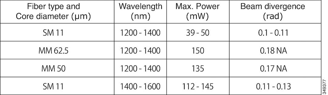
Pluggable optical modules comply with IEC 60825-1 Ed. 3 and 21 CFR 1040.10 and 1040.11 with or without exception for conformance with IEC 60825-1 Ed. 3 as described in Laser Notice No. 56, dated May 8, 2019. Statement 1255


Warning


Class 1 laser product. Statement 1008


Install Antennas for Cisco ISR1100-4GLTE Routers

Cisco ISR1100-4GLTE routers have two antenna terminals: Main and Diversity. Cisco ISR1100-4GLTE routers ship with one Omnidirectional Dipole Antenna (LTE-ANTM-SMA-D).

For information on installing the antenna provided with the router, see Installation Instructions for Cisco 4G LTEA, 4GLTE, and 3G Omnidirectional Dipole Antenna.


Note


For best performance, you are recommended to install two antennas.


For information on other supported antennas, see Antenna Selection Table.

For information on cables and accessories, see Cisco RF Cables and Accessories

Install and Remove SFP Modules

Install SFPs

Optical SFPs use a small laser to generate the fiber-optic signal. Keep the optical transmit and receive ports covered whenever a cable is not connected to the port.


Warning


Invisible laser radiation may be emitted from the end of the unterminated fiber cable or connector. Do not view directly with optical instruments. Viewing the laser output with certain optical instruments (for example, eye loupes, magnifiers, and microscopes) within a distance of 100 mm may pose an eye hazard. Statement 1056


To install an SFP module in your router:

  1. Read the “Safety Warnings” section , and disconnect the power supply before you replace any module.

  2. Slide the SFP into the router connector until it locks into position.


    Note


    The following image is for reference only.


    Figure 1. Install an SFP Module

    Caution


    Do not remove the optical port plugs from the SFP until you are ready to connect cabling.


  3. Connect the network cable to the SFP module.

Remove SFP Modules

Read the “Safety Warnings” section in this chapter, and disconnect the power supply before you replace any module.

  1. Disconnect all cables from the SFP module.


    Caution


    The latching mechanism used on many SFPs locks the SFP into place when cables are connected. Do not pull at the cabling in an attempt to remove the SFP.


  2. Disconnect the SFP latch.


    Note


    SFP modules use various latch designs to secure the module in the SFP port. Latch designs are not linked to SFP models or technology type. For information on the SFP technology type and model, see the label on the side of the SFP.


    Figure 2. Latch Mechanisms for Disconnecting SFP Modules
    • 1: Sliding latch

    • 2: Swing and slide latch

    • 3: Bale-clasp latch

    • 4: Plastic collar latch

  3. Grasp the SFP on both sides and remove it from the router.

Install the Micro SIM Card

This section describes how to install and replace the SIM card on router models that use a SIM.


Note


Do not touch any part of the exposed PCB circuit area when the SIM cover is removed.


Note


Make sure that the router is powered off before inserting or removing SIM card.


  1. Power off the router and disconnect the power cable from the power source.

  2. Remove the SIM cover plate by depressing the latch. Use a small flat-head screw-driver to depress the latch.

  3. Insert the SIM card by pushing it into the slot. Note that the orientation (indicated by the corner notch) of the SIM card is important and an icon is shown on the front of the router to assist you.

  4. After inserting the SIM card, replace the cover plate.