Cisco Catalyst SD-WAN Overlay Network Bring-Up Process

Network Overlay Bringup

Table 1. Feature History

Feature Name

Release Information

Description

Disk Encryption in On-Premises ESXi for a Virtual Machine Hosting Cisco SD-WAN Control Components

Cisco Catalyst SD-WAN Control Components Release 20.14.1

With this feature, you can apply disk encryption on the virtual disk When hosting Cisco SD-WAN Control Components in an on-premises installation, using a VMWare ESXi hypervisor hosted on a Cisco UCS platform.

Cisco SD-WAN Manager Persona and Storage Device

When you deploy Cisco SD-WAN Manager, you are prompted to choose a persona (from Cisco vManage Release 20.6.1) and a storage device for the Cisco SD-WAN Manager server the first time that the server boots up after Cisco SD-WAN Manager is installed.

Cisco SD-WAN Manager Persona

From Cisco vManage Release 20.6.1, each Cisco SD-WAN Manager server has a persona. The persona defines which services run on the server and defines the role that the server has in a Cisco SD-WAN Manager cluster. For related information on Cisco SD-WAN Manager persona, see “Cisco SD-WAN Manager Cluster.”

The persona that is configured for a Cisco SD-WAN Manager server cannot be changed.

Cisco SD-WAN Manager supports the following personas:

  • Compute + Data: Includes all services that are required for Cisco SD-WAN Manager, including services that are used for the application, statistics, configuration, messaging, and coordination. This persona should be used for a standalone node, and for the first node in a Cisco SD-WAN Manager cluster.

  • Compute: Includes services that are used for the application, configuration, messaging, and coordination. This persona does not include services that are used for statistics. A node with this persona cannot operate as a standalone node and must be part of a Cisco SD-WAN Manager cluster.

  • Data: Includes only services that are used for the application and statistics. A node with this persona cannot operate as a standalone node and must be part of a Cisco SD-WAN Manager cluster.

You are prompted to choose a persona for a Cisco SD-WAN Manager server the first time that the server boots up after Cisco SD-WAN Manager is installed. The prompt appears in the command line as follows:

1) COMPUTE_AND_DATA
2) DATA
3) COMPUTE
Select persona for vManage (1, 2 or 3):

When you see this prompt, type 1 to choose the Compute + Data persona, 2 to choose the Compute persona, or 3 to choose the Data persona. Then type y at the Are you sure prompt that displays to confirm your choice.

When you determine which persona to configure for a server, be aware that a Cisco SD-WAN Manager cluster supports any of the following deployments of nodes:

  • Three Compute+Data nodes

  • Three Compute+Data nodes and three Data nodes

  • Three Compute nodes and three Data nodes (supported only in an upgrade from an existing deployment)

If you require a different combination of nodes, contact your Cisco representative.

Cisco SD-WAN Manager Storage Device

Each Cisco SD-WAN Manager server has a storage device assigned to it. A storage device is a hard drive that is attached to the Cisco SD-WAN Manager server and that contains the /opt/data partition on which the database and other configuration information is saved.

You are prompted to choose a storage device for a Cisco SD-WAN Manager server the first time that the boots up after Cisco SD-WAN Manager is installed. You also are prompted whether you want to format the storage device.

The storage device assignment prompt appears in the command line as follows:

Available storage devices:

The prompt is followed by a list of available storage devices, each of which is preceded by a number. Type the number that corresponds to the storage device that you want to use for the server.

After you choose a storage device, you are prompted whether to format it. Type y to format the storage device, or type n to skip formatting. If you format a storage device, all data on the device is permanently deleted.

Bring-Up Sequence of Events

The bring-up process for edge devices—which includes authenticating and validating all the devices and establishing a functional overlay network—occurs with only minimal user input. From a conceptual point of view, the bring-up process can be divided into two parts, one that requires user input and one that happens automatically:

  1. In the first part, you design the network, create virtual machine (VM) instances for cloud routers, and install and boot hardware routers. Then, in Cisco SD-WAN Manager, you add the routers to the network and create configurations for each router. This process is described in the Summary of the User Portion of the Bring-Up Sequence.

  2. The second part of the bring-up process occurs automatically, orchestrated by the Cisco Catalyst SD-WAN software.​ As routers join the overlay network, they validate and authenticate themselves automatically, and they establish secure communication channels between each other. For Cisco SD-WAN Validators and Cisco SD-WAN Controllers, a network administrator must download the necessary authentication-related files from Cisco SD-WAN Manager, and then these Cisco SD-WAN Controllers and Cisco SD-WAN Validators automatically receive their configurations from Cisco SD-WAN Manager. For vEdge Cloud routers, you must generate a certificate signing request (CSR), install the received certificate, and then upload the serial number that is included in the certificate to Cisco SD-WAN Manager. After Cisco hardware routers start, they are authenticated on the network and receive their configurations automatically from Cisco SD-WAN Manager through a process called zero-touch provisioning (ZTP). This process is described in the Automatic Portions of the Bring-Up Sequence.

    The end result of this two-part process is an operational overlay network.

    This topic describes the sequence of events that occurs during the bring-up process, starting with the user portion and then explaining how automatic authentication and device validation occur.

Sequence of Events of the Bring-Up Process

From a functional point of view, the task of bringing up the routers in the overlay network occurs in the following sequence:
Figure 1. Bring-Up Sequence of Events
  1. The Cisco SD-WAN Manager software starts on a server in the data center.

  2. The Cisco SD-WAN Validator starts on a server in the DMZ.

  3. The Cisco SD-WAN Controller starts on a server in the data center.

  4. Cisco SD-WAN Manager and the Cisco SD-WAN Validator authenticate each other, Cisco SD-WAN Manager and the Cisco SD-WAN Controller authenticate each other, and the Cisco SD-WAN Controller and the Cisco SD-WAN Validator securely authenticate each other.

  5. Cisco SD-WAN Manager sends configurations to the Cisco SD-WAN Controller and the Cisco SD-WAN Validator.

  6. The routers start in the network.

  7. The routers authenticate themselves with the Cisco SD-WAN Validator.

  8. The routers authenticate themselves with Cisco SD-WAN Manager.

  9. The routers authenticate themselves with the Cisco SD-WAN Controller.

  10. Cisco SD-WAN Manager sends configurations to the routers.

Before you start the bring-up process, note the following:

  • To provide the highest level of security, only authenticated and authorized routers can access and participation in the Cisco Catalyst SD-WAN overlay network. To this end, the Cisco SD-WAN Controller performs automatic authentication on all the routers before they can send data traffic over the network.

  • After the routers are authenticated, data traffic flows, regardless of whether the routers are in a private address space (behind a NAT gateway) or in a public address space.

To bring up the hardware and software components in a Cisco Catalyst SD-WAN overlay network, a transport network (also called a transport cloud), which connects all the routers and other network hardware components, must be available. Typically, these components are in data centers and branch offices. The only purpose of the transport network is to connect all the network devices in the domain. The Cisco Catalyst SD-WAN solution is agnostic with regards to the transport network, and, therefore, can be any type, including the internet, Multiprotocol Label Switching (MPLS), Layer 2 switching, Layer 3 routing, and Long-Term Evolution (LTE), or any mixture of transports.

For hardware routers, you can use the Cisco Catalyst SD-WAN zero-touch provisioning (ZTP) SaaS to bring up the routers. For more information on automatic process to bring-up hardware in the overlay network, see Prepare Routers for ZTP.


Note


Starting from Cisco vManage Release 20.3.1, if you assign Cisco SD-WAN Manager VPN0 IP address in the 172.17.0.0/16 subnet, it cannot form control connections to edge devices (IOS XE SD-WAN and SD-routing).


Steps to Bring Up the Overlay Network

Bringing Up the Overlay Network

The following table lists the tasks for bringing up the overlay network using Cisco SD-WAN Manager.

Table 2.

Bring-Up Task

Step-by-Step Procedure

Step 1: Start the Cisco SD-WAN Manager.

  1. On the hypervisor, create a VM instance.

  2. Boot Cisco SD-WAN Manager server, start the VM, and enter login information.

  3. From the Cisco SD-WAN Manager menu, choose Administration > Settings, configure certificate authorization settings. Select Automated to allow the certificate-generation process to occur automatically when a CSR is generated for a controller device.

  4. From the Cisco SD-WAN Manager menu, choose Configuration > Certificates, generate the CSR.

  5. Check for a confirmation email from Symantec that your request has been received.

  6. Check for an email from Symantec that Viptela has approved your request and the certificate is signed.

  7. From the Cisco SD-WAN Manager menu, choose Configuration > Devices, and check if the certificate has been installed.

Step 2: Start the Cisco SD-WAN Validator.

  1. On the hypervisor, create a VM instance.

  2. Boot the Cisco SD-WAN Validator server and start the VM.

  3. From the Cisco SD-WAN Manager menu, choose Configuration > Devices > Controllers, add Cisco SD-WAN Validator and generate the CSR.

    Note


    Starting from Cisco IOS XE Catalyst SD-WAN Release 17.13.1a, the Controllers tab is renamed as the Control Components tab to stay consistent with Cisco Catalyst SD-WAN rebranding.

  4. Check for a confirmation email from Symantec that your request has been received.

  5. Check for an email from Symantec that Viptela has approved your request and the certificate is signed.

  6. From the Cisco SD-WAN Manager menu, choose Configuration > Devices, and check if the certificate has been installed.

  7. From the Cisco SD-WAN Manager menu, choose Configuration > Templates:

    1. Create a configuration template for the Cisco SD-WAN Validator.

    2. Attach the template to Cisco SD-WAN Validator.

  8. From the Cisco SD-WAN Manager menu, choose Monitor > Overview, and verify that the Cisco SD-WAN Validator is operational.

    Cisco vManage Release 20.6.x and earlier: From the Cisco SD-WAN Manager menu, choose Dashboard > Main Dashboard, and verify that the Cisco SD-WAN Validator is operational.

Step 3: Start the Cisco Catalyst SD-WAN Controller.

  1. On the hypervisor, create a VM instance.

  2. Boot the Cisco SD-WAN Controller server and start the VM.

  3. From the Cisco SD-WAN Manager menu, choose Configuration > Devices > Controller, add Cisco Catalyst SD-WAN Controller and generate the CSR.

    Note


    Starting from Cisco IOS XE Catalyst SD-WAN Release 17.13.1a, the Controllers tab is renamed as the Control Components tab to stay consistent with Cisco Catalyst SD-WAN rebranding.

  4. Check for a confirmation email from Symantec that your request has been received.

  5. Check for an email from Symantec that Viptela has approved your request and the certificate is signed.

  6. From the Cisco SD-WAN Manager menu, choose Configuration > Devices, check that the certificate has been installed.

  7. From the Cisco SD-WAN Manager menu, choose Configuration > Templates:

    1. Create a configuration template for Cisco Catalyst SD-WAN Controller.

    2. Attach the template to Cisco Catalyst SD-WAN Controller.

  8. From the Cisco SD-WAN Manager menu, choose Monitor > Overview, and verify that Cisco Catalyst SD-WAN Controller is operational.

    Cisco vManage Release 20.6.x and earlier: From the Cisco SD-WAN Manager menu, choose Dashboard > Main Dashboard, and verify that Cisco Catalyst SD-WAN Controller is operational.

Step 4: Configure the router.

  1. From the Cisco SD-WAN Manager menu, choose Configuration > Devices > WAN Edge List, upload the router authorized serial number file.

  2. From the Cisco SD-WAN Manager menu, choose Configuration > Certificates > WAN Edge List, check that the router's chassis and serial number are in the list.

  3. From the Cisco SD-WAN Manager menu, choose Configuration > Certificates > WAN Edge List, authorize each router by marking it Valid in the Validity column.

  4. From the Cisco SD-WAN Manager menu, choose Configuration > Certificates > WAN Edge List, send the WAN Edge list to the controller devices.

  5. From the Cisco SD-WAN Manager menu, choose Configuration > Templates:

    1. Create a configuration template for the router.

    2. Attach the template to the router.

Step 5: Connect AC power and boot a hardware router.

  1. Connect AC power to the router.

  2. If needed, flip the On/Off switch on the rear of the router to the ON position.

  3. From the Cisco SD-WAN Manager menu, choose Monitor > Overview or choose Monitor > Devices > Device Dashboard, verify that the router is operational.

    Cisco vManage Release 20.6.x and earlier: From the Cisco SD-WAN Manager menu, choose Dashboard > Main Dashboard or choose Monitor > Network > Device Dashboard, verify that the router is operational.

Summary of the User Portion of the Bring-Up Sequence

Generally, what you do to bring up the Cisco Catalyst SD-WAN overlay network is what you do to bring up any network. You plan out the network, create device configurations, and then deploy the network hardware and software components. These components include all the Cisco vEdge devices, all the traditional routers that participate in the overlay network, and all the network devices that provide shared services across the overlay network, such as firewalls, load balancers, and IDP systems.​

The following table summarizes the steps for the user portion of the Cisco Catalyst SD-WAN overlay network bring-up sequence. The details of each step are provided in the articles that are listed in the Procedure column. While you can bring up the Cisco vEdge devices in any order, it is recommended that you deploy them in the order listed below, which is the functional order in which the devices verify and authenticate themselves.

If your network has firewall devices, see Firewall Ports for Cisco Catalyst SD-WAN Deployments.

Table 3.

Workflow

Procedure

1

Plan out your overlay network. See Components of the Cisco Catalyst SD-WAN Solution.

2

On paper, create device configurations that implement the desired architecture and functionality. See the Software documentation for your software release.

3

Download the software images.

4

Deploy Cisco SD-WAN Manager in the data center:

  1. Create a Cisco SD-WAN Manager VM instance, either on an ESXi or a KVM hypervisor.

  2. Create either a minimal or a full configuration for each Cisco SD-WAN Manager server.

  3. Configure certificate settings and generate a certificate for Cisco SD-WAN Manager.

  4. Create a Cisco SD-WAN Manager cluster.

5

Deploy the Cisco SD-WAN Validator:

  1. Create a Cisco SD-WAN Validator VM instance, either on an ESXi or a KVM hypervisor.

  2. Create a minimal configuration for the Cisco SD-WAN Validator.

  3. Add the Cisco SD-WAN Validator to the overlay network. During this process, you generate a certificate for the Cisco SD-WAN Validator.

  4. Create a full configuration for the Cisco SD-WAN Validator.

6

Deploy the Cisco SD-WAN Controller in the data center:

  1. Create a Cisco SD-WAN Controller VM instance, either on an ESXi or a KVM hypervisor.

  2. Create a minimal configuration for the Cisco SD-WAN Controller.

  3. Add the Cisco SD-WAN Controller to the overlay network. During this process, you generate a certificate for the Cisco SD-WAN Controller.

  4. Create a full configuration for the Cisco SD-WAN Controller.

7

Deploy the Cisco vEdge routers in the overlay network:

  1. For software vEdge Cloud routers, create a VM instance, either on an AWS server, or on an ESXi or a KVM hypervisor.

  2. For software vEdge Cloud routers, send a certificate signing request to Symantec and then install the signed certificate on the router.

  3. From Cisco SD-WAN Manager, send the serial numbers of all Cisco vEdge routers to the Cisco SD-WAN Controller and Cisco SD-WAN Validator in the overlay network.

  4. Create a full configuration for the Cisco vEdge routers.

Automatic Portions of the Bring-Up Sequence

After the Cisco vEdge devices boot and start running with their initial configurations, the second part of the bring-up process begins automatically. This automatic process is led by the Cisco SD-WAN Validator, as illustrated in the figure below. Under the leadership of the Cisco SD-WAN Validator software, the Cisco vEdge devices set up encrypted communication channels between themselves. Over these channels, the devices automatically validate and authenticate each other, a process that establishes an operational overlay network. Once the overlay network is running, the Cisco vEdge devices automatically receive and activate their full configurations from the Cisco SD-WAN Manager server. (The exception is the Cisco SD-WAN Manager. You must manually configure each Cisco SD-WAN Manager server itself).

Figure 2. Cisco SD-WAN Validator Automated Bring-Up Sequence
After the initial configurations, Cisco vBond Orchestrator initates the automatic bring-up sequence.

The following sections explain what happens under the covers, during the automatic portion of the bring-up process. This explanation is provided to help you understand the detailed workings of the Cisco Catalyst SD-WAN software so that you can better appreciate the means by which the Cisco Catalyst SD-WAN solution creates a highly secure overlay framework to support your networking requirements.

User Input Required for the ZTP Automatic Authentication Process

The automatic validation and authentication of Cisco vEdge devices that occurs during the bringup process can happen only if Cisco SD-WAN Controllers and Cisco SD-WAN Validators know the serial and chassis numbers of the devices that are permitted in the network. Let's first define these two terms:

  • Serial number—​Each Cisco vEdge device has a serial number, which is a 40-byte number that is included in the device's certificate. For Cisco SD-WAN Validator and Cisco SD-WAN Controller, the certificate can be provided by Symantec or by an enterprise root CA. For the vEdge routers, the certificate is provided in the hardware's trusted board ID chip.

  • Chassis number—In addition to a serial number, each vEdge router is identified by a chassis number. Because the vEdge router is the only Cisco SD-WAN Controller manufactured hardware, it is the only Cisco vEdge device that has a chassis number. There is a one-to-one mapping between a vEdge router's serial number and its chassis number.

The Cisco SD-WAN Controllers and Cisco SD-WAN Validators learn the serial and chassis numbers during the initial configuration of these devices:

  • Cisco SD-WAN Controller authorized serial numbers—The Cisco SD-WAN Manager learns the serial numbers for all Cisco SD-WAN Controllers that are allowed to be in the network while it is creating a CSR and installing the signed certificate. You download these serial numbers to Cisco SD-WAN Validator, and Cisco SD-WAN Validator pushes them to the Cisco Catalyst SD-WAN Controller during the automatic authentication process.

  • vEdge authorized serial number file—This file contains the serial and chassis numbers of all the vEdge routers that are allowed to be in the network. You upload this file to Cisco SD-WAN Validators and Cisco SD-WAN Controllers.

In addition to the device serial and chassis numbers, the automatic validation and authentication procedure depends on having each device configured with the same organization name. You configure this name on Cisco SD-WAN Manager, and it is included in the configuration file on all devices. The organization name must be identical on all the devices that belong to a single organization (the name is case-sensitive). The organization name is also included in the certificate for each device, which is created either by Cisco Catalyst SD-WAN or by an enterprise root CA.

Authentication between Cisco Catalyst SD-WAN Controller and Cisco Catalyst SD-WAN Validator

From a functional point of view, the first two devices on the Cisco Catalyst SD-WAN overlay network that validate and authenticate each other are Cisco SD-WAN Controller and Cisco SD-WAN Validator. This process is initiated by Cisco SD-WAN Controller.

Figure 3. Authentication of Cisco SD-WAN Controller and Cisco SD-WAN Validator
Validate and authenticate of Cisco vSmart Controller and Cisco vBond Orchestrator. This process is initiated by Cisco vSmart Controller.
When Cisco SD-WAN Controller comes up, it initiates a connection to Cisco SD-WAN Validator, which is how Cisco SD-WAN Validator learns about Cisco SD-WAN Controller. These two devices then automatically begin a two-way authentication process—Cisco SD-WAN Controller authenticates itself with , and Cisco SD-WAN Validator authenticates itself with Cisco SD-WAN Validator. The two-way handshaking between the two devices during the authentication process occurs in parallel. However, for clarity, the figure here, which is a high-level representation of the authentication steps, illustrates the handshaking sequentially. If the authentication handshaking succeeds, a permanent DTLS communication channel is established between the Cisco SD-WAN Controller and Cisco SD-WAN Validator devices. If any one of the authentication steps fails, the device noting the failure tears down the connection between the two devices, and the authentication attempt terminates.

The Cisco SD-WAN Controller knows how to reach Cisco SD-WAN Validator, because one of the parameters that you provision when you configure it is the IP address or DNS name of Cisco SD-WAN Validator. Cisco SD-WAN Validator is primed to respond to requests from Cisco SD-WAN Validator because:

  • It knows that its role is to be the authentication system, because you included this information in the Cisco SD-WAN Validator configuration.

  • You downloaded the Cisco SD-WAN Controller authorized serial numbers from Cisco SD-WAN Manager to Cisco SD-WAN Validator.

If Cisco SD-WAN Validator has not yet started when Cisco SD-WAN Controller initiates the authentication process, Cisco SD-WAN Controller periodically attempts to initiate a connection until it is successful.

Below is a more detailed step-by-step description of how the automatic authentication occurs between Cisco SD-WAN Controller and Cisco SD-WAN Validator.

To initiate a session between Cisco SD-WAN Controller and Cisco SD-WAN Validator, Cisco SD-WAN Controller initiates an encrypted DTLS connection to Cisco SD-WAN Validator. The encryption is provided by RSA. Each device automatically generates an RSA private key‒public key pair when it boots.

Over this encrypted channel, Cisco SD-WAN Controller and Cisco SD-WAN Validator authenticate each other. Each device authenticates the other in parallel. For our discussion, let's start with Cisco SD-WAN Controller authentication of Cisco SD-WAN Validator:

  1. Cisco SD-WAN Validator sends its trusted root CA signed certificate to the Cisco SD-WAN Controller.

  2. Cisco SD-WAN Validator sends the vEdge authorized serial number file to the Cisco SD-WAN Controller.

  3. Cisco SD-WAN Controller uses its chain of trust to extract the organization name from the certificate and compares it to the organization name that is configured on Cisco SD-WAN Controller. If the two organization names match, Cisco SD-WAN Controller knows that the organization of Cisco SD-WAN Validator is proper. If they do not match, Cisco Catalyst SD-WAN Controller tears down the DTLS connection.

  4. Cisco Catalyst SD-WAN Controller uses the root CA chain to verify that the certificate has indeed been signed by the root CA (either Symantec or the enterprise CA). If the signature is correct, Cisco Catalyst SD-WAN Controller knows that the certificate itself is valid. If the signature is incorrect, Cisco Catalyst SD-WAN Controller tears down the DTLS connection.

Figure 4. Cisco SD-WAN Controller authenticates Cisco SD-WAN Validator
Over the encrypted channel, Cisco vSmart Controller and Cisco vBond Orchestrator authenticates each other.

After performing these two checks, Cisco SD-WAN Controller authentication of Cisco SD-WAN Validator is complete.

In the other direction, Cisco SD-WAN Validator​ authenticates Cisco SD-WAN Controller:

  1. Cisco SD-WAN Controller sends its trusted root CA signed certificate to Cisco SD-WAN Validator.

  2. Cisco SD-WAN Validator uses its chain of trust to extract Cisco SD-WAN Controller serial number from the certificate. The number must match one of the numbers in the Cisco SD-WAN Controller authorized serial number file. If there is no match, Cisco SD-WAN Validator tears down the DTLS connection.

  3. Cisco SD-WAN Validator uses its chain of trust to extract the organization name from the certificate and compares it to the organization name that is configured on Cisco SD-WAN Validator. If the two organization names match, the Cisco SD-WAN Validator knows that the organization of Cisco SD-WAN Controller is proper. If they do not match, Cisco SD-WAN Validator tears down the DTLS connection.

  4. The Cisco SD-WAN Validator uses the root CA chain to verify that the certificate has indeed been signed by the root CA (either Symantec or the enterprise CA). If the signature is correct, Cisco SD-WAN Validator knows that the certificate itself is valid. If the signature is incorrect, Cisco SD-WAN Validator tears down the DTLS connection.

Figure 5. Cisco SD-WAN Validator authenticates Cisco SD-WAN Controller
Cisco vBond Orchestrator authenticates Cisco vSmart Controller performing three checks.

After performing these three checks, the Cisco SD-WAN Validator authentication of Cisco SD-WAN Validator is complete.

After the bidirectional authentication completes between the two devices, the DTLS connection between Cisco SD-WAN Validator and Cisco SD-WAN Controller transitions from being a temporary connection to being a permanent connection, and the two devices establish an OMP session over the connection.

In a domain that has multiple Cisco SD-WAN Controllers for redundancy, this process repeats between each pair of Cisco SD-WAN Controller and Cisco SD-WAN Validator devices. In coordination with Cisco SD-WAN Validator, Cisco SD-WAN Controllers learn about each other and they synchronize their route information. It is recommended that you connect the different Cisco SD-WAN Controller to the WAN network through different NAT devices for higher availability.

A Cisco SD-WAN Validator has only as many permanent DTLS connections as the number of Cisco SD-WAN Controllers in the network topology. These DTLS connections are part of the network's control plane; no data traffic flows over them. After all Cisco SD-WAN Controllers have registered themselves with Cisco SD-WAN Validator, Cisco SD-WAN Validator and Cisco SD-WAN Controllers are ready to validate and authenticate the vEdge routers in the Cisco Catalyst SD-WAN network.

Authentication Between Cisco Catalyst SD-WAN Controllers

In a domain with multiple Cisco SD-WAN Controllers, the controllers must authenticate each other so that they can establish a full mesh of permanent DTLS connection between themselves for synchronizing OMP routes. Cisco SD-WAN Controller learns the IP address of the other Cisco SD-WAN Controller from Cisco SD-WAN Validator.

Cisco SD-WAN Controller learns about the possibility of other Cisco SD-WAN Controllers being present on the network during the authentication handshaking with the Cisco SD-WAN Validator, when it receives a copy of the Cisco SD-WAN Controller authorized serial number file. If this file has more than one serial number, it indicates that the network may, at some point, have multiple Cisco SD-WAN Controllers.

As one Cisco SD-WAN Controller authenticates with Cisco SD-WAN Validator, Cisco SD-WAN Validator sends Cisco SD-WAN Controller the IP address of other Cisco SD-WAN Controllers it has authenticated with. If Cisco SD-WAN Validator later learns of another Cisco SD-WAN Controller, it sends that controller's address to the other already authenticated Cisco SD-WAN Controllers.

Then, Cisco SD-WAN Controllers perform the steps below to authenticate each other. Again, each device authenticates the other in parallel, but for clarity, we describe the process sequentially.

  1. Cisco SD-WAN Controller1 (vSmart1) initiates an encrypted DTLS connection to Cisco SD-WAN Controller2 (vSmart2) and sends its trusted root CA signed certificate to Cisco SD-WAN Controller2.

  2. Cisco SD-WAN Controller2 uses its chain of trust to extract the Cisco SD-WAN Controller1's serial number. The number must match one of the numbers in the Cisco SD-WAN Controller authorized serial number file. If there is no match, Cisco SD-WAN Controller2 tears down the DTLS connection.

  3. Cisco SD-WAN Controller2 uses its chain of trust to extract the organization name from the certificate and compares it to the locally configured organization name. If the two organization names match, Cisco SD-WAN Controller2 knows that the organization of Cisco SD-WAN Controller1 is proper. If they do not match, Cisco SD-WAN Controller2 tears down the DTLS connection.

  4. Cisco SD-WAN Controller2 uses the root CA chain to verify that the certificate has indeed been signed by the root CA (either Symantec or the enterprise CA). If the signature is correct, Cisco SD-WAN Controller2 knows that the certificate itself is valid. If the signature is incorrect, Cisco SD-WAN Controller2 tears down the DTLS connection.

After performing these three checks, Cisco SD-WAN Controller2​ authentication of Cisco SD-WAN Controller1 is complete.

Now, Cisco SD-WAN Controller1 authenticates Cisco SD-WAN Controller2, performing the same steps as above.

  1. First, Cisco SD-WAN Controller2 sends its trusted root CA signed certificate to Cisco SD-WAN Controller1.

  2. Cisco SD-WAN Controller1 uses its chain of trust to extract the Cisco SD-WAN Controller2's serial number. The number must match one of the numbers in the Cisco SD-WAN Controller authorized serial number file. If there is no match, Cisco SD-WAN Controller1 tears down the DTLS connection.

  3. Cisco SD-WAN Controller1 uses its chain of trust to extract the organization name from the certificate and compares it to the locally configured organization name. If the two organization names match, Cisco SD-WAN Controller2 knows that the organization of Cisco SD-WAN Controller2 is proper. If they do not match, Cisco SD-WAN Controller1 tears down the DTLS connection.

  4. Cisco SD-WAN Controller1 uses the root CA chain to verify that the certificate has indeed been signed by the root CA (either Symantec or the enterprise CA). If the signature is correct, Cisco SD-WAN Controller2 knows that the certificate itself is valid. If the signature is incorrect, Cisco SD-WAN Controller1 tears down the DTLS connection.

Figure 6. Authentication of Cisco SD-WAN Controller
Authentication of each of the Cisco vSmart controllers by performing three checks.

After performing these three checks, Cisco SD-WAN Controller1​ authentication of Cisco SD-WAN Controller2 is complete, and the temporary DTLS connection between the two devices becomes permanent.

After all the Cisco SD-WAN Controllers have registered themselves with , Cisco SD-WAN Validator and Cisco SD-WAN Controllers are ready to validate and authenticate the vEdge routers in the Cisco Catalyst SD-WAN network.

Authentication between Cisco Catalyst SD-WAN Validator and a Cisco vEdge Router

When you deploy a Cisco vEdge router in the network, it first needs to do two things:

  • Establish a secure connection with Cisco SD-WAN Manager so that it can receive its full configuration.

  • Establish a secure connection with Cisco Catalyst SD-WAN Controller can begin participating in the Cisco Catalyst SD-WAN overlay network.

When a Cisco vEdge device comes up, how does it automatically discover Cisco SD-WAN Manager and Cisco Catalyst SD-WAN Controller and establish connections with them? It does so with help from Cisco SD-WAN Validator. The initial configuration on the Cisco vEdge router contains the Cisco SD-WAN Validator system’s IP address (or DNS name). Using this information, the Cisco vEdge router establishes a DTLS connection with Cisco SD-WAN Validator, and the two devices authenticate each other to confirm that they are valid Cisco vEdge devices. Again, this authentication is a two-way process that happens automatically. When the authentication completes successfully, Cisco SD-WAN Validator sends the Cisco vEdge router the IP addresses of Cisco SD-WAN Manager and Cisco Catalyst SD-WAN Controller. Then, the Cisco vEdge router tears down its connection with Cisco SD-WAN Validator and begins establishing secure DTLS connections with the othe two devices.

Figure 7. Automatic Authentication of Cisco vEdge Router and Cisco SD-WAN Validator
Two-way automatic authentication of Cisco vEdge router and Cisco vBond orchestrator.

After you boot Cisco vEdge routers and manually perform the initial configuration, they automatically start looking for their Cisco SD-WAN Validator. Cisco SD-WAN Validator and Cisco SD-WAN Controllers are able to recognize and authenticate the Cisco vEdge routers in part because you have installed the Cisco vEdge authorized device list file on both these devices.

After you boot a Cisco vEdge router, you manually perform the initial configuration, at a minimum setting the IP address of DNS name of Cisco SD-WAN Validator. The Cisco vEdge router uses this address information to reach Cisco SD-WAN Validator. Cisco SD-WAN Validator is primed to respond to requests from a Cisco vEdge router because:

  • It knows that its role is to be the authentication system, because you included this information in the initial Cisco SD-WAN Validator configuration.

  • As part of the initial configuration, you installed the Cisco vEdge authorized serial number file on Cisco SD-WAN Validator.

If Cisco SD-WAN Validator has not yet started when a Cisco vEdge router initiates the authentication process, the Cisco vEdge router periodically attempts to initiate a connection until the attempt succeeds.

Below is a more detailed step-by-step description of how the automatic authentication occurs between Cisco SD-WAN Validator and a Cisco vEdge router.

First, the Cisco vEdge router initiates an encrypted DTLS connection to the public IP address of Cisco SD-WAN Validator. The encryption is provided by RSA. Each device automatically generates an RSA private key‒public key pair when it boots. Cisco SD-WAN Validator receives the Cisco vEdge router's original interface address and uses the outer IP address in the received packet to determine whether the Cisco vEdge router is behind a NAT. If it is, Cisco SD-WAN Validator creates a mapping of the Cisco vEdge router's public IP address and port to its private IP address.

Over this encrypted DTLS channel, the Cisco vEdge router and Cisco SD-WAN Validator proceed to authenticate each other. As with other device authentication, the Cisco vEdge router and Cisco SD-WAN Validator authenticate each other in parallel. We start our discussion by describing how the Cisco vEdge router authenticates Cisco SD-WAN Validator:

  1. Cisco SD-WAN Validator sends its trusted root CA signed certificate to the Cisco vEdge router.​

  2. The Cisco vEdge router uses its chain of trust to extract the organization name from the certificate and compares it to the organization name that is configured on the router itself. If the two organization names match, the Cisco vEdge routers knows that the organization of Cisco SD-WAN Validator is proper. If they do not match, the Cisco vEdge router tears down the DTLS connection.

  3. The Cisco vEdge router uses the root CA chain to verify that the certificate has indeed been signed by the root CA (either Symantec or the enterprise CA). If the signature is correct, the Cisco vEdge router knows that the certificate itself is valid. If the signature is incorrect, the Cisco vEdge router tears down the DTLS connection.

Figure 8. Cisco vEdge router authenticates Cisco SD-WAN Validator
Cisco vEdge router authenticates Cisco vBond orchestrator by performing two checks and validates Cisco vEdge router.

After performing these two checks, the Cisco vEdge router knows that Cisco SD-WAN Validator is valid, and its authentication of Cisco SD-WAN Validator is complete.

In the opposite direction, Cisco SD-WAN Validator authenticates the Cisco vEdge router:

  1. Cisco SD-WAN Validator sends a challenge to the Cisco vEdge router. The challenge is a 256-bit random value.

  2. The Cisco vEdge router sends a response to the challenge that includes the following:

    • Cisco vEdge serial number

    • Cisco vEdge chassis number

    • Cisco vEdge board ID certificate

    • 256-bit random value signed by the Cisco vEdge router's private key

  3. Cisco SD-WAN Validator compares the serial and chassis numbers to the list in its Cisco vEdge authorized device list file. The numbers must match one of the number pairs in the file. If there is no match, Cisco SD-WAN Validator tears down the DTLS connection.

  4. Cisco SD-WAN Validator checks that the signing of the 256-bit random value is proper. It does this using the Cisco vEdge router's public key, which it extracts from the router's board ID certificate. If the signing is not correct, Cisco SD-WAN Validator tears down the DTLS connection.

  5. Cisco SD-WAN Validator uses the root CA chain from the Cisco vEdge routers board ID certificate to validate that the board ID certificate is itself valid. If the certificate is not valid, Cisco SD-WAN Validator tears down the DTLS connection.

Figure 9. Cisco SD-WAN Validator authenticates Cisco vEdge router
Cisco vBond orchestrator authenticates Cisco vEdge router performing three checks and validates Cisco vEdge router.

After performing these three checks, Cisco SD-WAN Validator knows that Cisco vEdge router is valid, and its authentication of the router is complete.

When the two-way authentication succeeds, Cisco SD-WAN Validator performs the final step of its orchestration, sending messages to the Cisco vEdge router and Cisco Catalyst SD-WAN Controller in parallel. To the Cisco vEdge router, Cisco SD-WAN Validator sends the following:

  • The IP addresses of Cisco SD-WAN Controllers in the network so that the Cisco vEdge router can initiate connections to them. The address can be public IP addresses, or for the controllers that are behind a NAT gateway, the addresses are a list of the public and private IP addresses and port numbers. If the Cisco vEdge router is behind a NAT gateway, Cisco SD-WAN Validator requests that the Cisco vEdge router initiate a session with Cisco Catalyst SD-WAN Controller.

  • Serial numbers of Cisco SD-WAN Controllers that are authorized to be in the network.

To Cisco Catalyst SD-WAN Controller, Cisco SD-WAN Validator sends the following:

  • A message announcing the new Cisco vEdge router in the domain.

  • If the Cisco vEdge router is behind a NAT gateway, Cisco SD-WAN Validator sends a request to Cisco Catalyst SD-WAN Controller to initiate a session with the Cisco vEdge router.

Then, the Cisco vEdge router tears down the DTLS connection with the Cisco SD-WAN Validator.

Authentication between the Cisco vEdge Router and Cisco SD-WAN Manager

After the Cisco vEdge router and Cisco SD-WAN Validator have authenticated each other, the Cisco vEdge router receives its full configuration over a DTLS connection with Cisco SD-WAN Manager:

  1. The Cisco vEdge router establishes a DTLS connection with Cisco SD-WAN Manager.

  2. Cisco SD-WAN Manager server sends the configuration file to the Cisco vEdge router.

  3. When the Cisco vEdge router receives the configuration file and activates its full configuration.

  4. The Cisco vEdge router starts advertising prefixes to Cisco SD-WAN Controller.

If you are not using Cisco SD-WAN Manager, you can log in to the Cisco vEdge router and either manually load its configuration file or manually configure the router.

Below is a more detailed step-by-step description of how the automatic authentication occurs between a Cisco vEdge router and Cisco SD-WAN Manager.

First, the Cisco vEdge router initiates an encrypted DTLS connection to the IP address of Cisco SD-WAN Manager. The encryption is provided by RSA. Each device automatically generates an RSA private key‒public key pair when it boots. Cisco SD-WAN Manager receives the Cisco vEdge router's original interface address and uses the outer IP address in the received packet to determine whether the Cisco vEdge router is behind a NAT. If it is, Cisco SD-WAN Manager creates a mapping of the Cisco vEdge router's public IP address and port to its private IP address.

Over this encrypted DTLS channel, the Cisco vEdge router and Cisco SD-WAN Manager proceed to authenticate each other. As with other device authentication, the Cisco vEdge router and Cisco SD-WAN Manager authenticate each other in parallel. We start our discussion by describing how the Cisco vEdge router authenticates Cisco SD-WAN Manager:

  1. Cisco SD-WAN Manager sends its trusted root CA signed certificate to the Cisco vEdge router.​

  2. The Cisco vEdge router uses its chain of trust to extract the organization name from the certificate and compares it to the organization name that is configured on the router itself. If the two organization names match, the Cisco vEdge routers knows that the organization of Cisco SD-WAN Manager is proper. If they do not match, the Cisco vEdge router tears down the DTLS connection.

  3. The Cisco vEdge router uses the root CA chain to verify that the certificate has indeed been signed by the root CA (either Symantec or the enterprise CA). If the signature is correct, the Cisco vEdge router knows that the certificate itself is valid. If the signature is incorrect, the Cisco vEdge router tears down the DTLS connection.

Figure 10. Cisco vEdge Router Authenticates Cisco SD-WAN Manager
Automatic authentication of Cisco vEdge router and Cisco vManage by performing two checks and validates Cisco vManage.

After performing these two checks, the Cisco vEdge router knows that Cisco SD-WAN Manager is valid, and its authentication of Cisco SD-WAN Manager is complete.

In the opposite direction, Cisco SD-WAN Manager authenticates the Cisco vEdge router:

  1. Cisco SD-WAN Manager sends a challenge to the Cisco vEdge router. The challenge is a 256-bit random value.

  2. The Cisco vEdge router sends a response to the challenge that includes the following:

    • Cisco vEdge serial number

    • Cisco vEdge chassis number

    • Cisco vEdge board ID certificate (for a hardware Cisco vEdge router) or the signed certification (for a Cisco vEdge Cloud router)

    • 256-bit random value signed by the Cisco vEdge router's private key

  3. Cisco SD-WAN Manager compares the serial and chassis numbers to the list in its Cisco vEdge authorized device list file. The numbers must match one of the number pairs in the file. If there is no match, Cisco SD-WAN Managerthe Cisco SD-WAN Manager NMS tears down the DTLS connection.

  4. Cisco SD-WAN Manager checks that the signing of the 256-bit random value is proper. It does this using the Cisco vEdge router's public key, which it extracts from the router's board ID certificate. If the signing is not correct, Cisco SD-WAN Manager tears down the DTLS connection.

  5. Cisco SD-WAN Manager uses the root CA chain from the Cisco vEdge routers board ID certificate to validate that the board ID certificate is itself valid. If the certificate is not valid, Cisco SD-WAN Manager tears down the DTLS connection.

Figure 11. Cisco SD-WAN Manager Authenticates Cisco vEdge Router
Cisco vEdge router authenticates Cisco vManage by performing three checks and validates Cisco vEdge router

After performing these three checks, Cisco SD-WAN Manager knows that Cisco vEdge router is valid, and its authentication of the router is complete.

When the two-way authentication succeeds, Cisco SD-WAN Manager server sends the configuration file to the Cisco vEdge router. When the Cisco vEdge router receives the configuration file, it activates its full configuration and starts advertising prefixes to Cisco SD-WAN Controller.

Authentication between Cisco Catalyst SD-WAN Controller and the Cisco vEdge Router

The last step in the automatic authentication process is for Cisco SD-WAN Controller and the Cisco vEdge router to authenticate each other. In this step, Cisco SD-WAN Controller performs authentication to ensure that the Cisco vEdge router belongs in its network, and the Cisco vEdge router also authenticates Cisco SD-WAN Controller. When the authentication completes, the DTLS connection between the two devices becomes permanent, and Cisco SD-WAN Controller establishes an OMP peering session running over the DTLS connection. Then, the Cisco vEdge router starts sending data traffic over the Cisco Catalyst SD-WAN overlay network.

Figure 12. Authentication of Cisco SD-WAN Controller and Cisco Cisco vEdge Router
The image illustrates authentication of Cisco vSmart controller and Cisco vEdge router with each other, which is the last step in the automatic authentication process.

In this section below, is a more detailed step-by-step description of how the automatic authentication occurs between Cisco SD-WAN Controller and a Cisco vEdge router.

To initiate a session between Cisco SD-WAN Controller and a Cisco vEdge router, one of the two devices initiates an encrypted DTLS connection to the other. The encryption is provided by RSA. Each device automatically generates an RSA private key‒public key pair when it boots.

The authentication between Cisco SD-WAN Controller and a Cisco vEdge router is a two-way process that occurs in parallel. Let's start our discussion with how Cisco SD-WAN Controller authenticates a Cisco vEdge router:

  1. Cisco SD-WAN Controller sends a challenge to the Cisco vEdge router. The challenge is a 256-bit random value.

  2. The Cisco vEdge router sends a response to the challenge that includes the following:

    • Cisco vEdge serial number

    • Cisco vEdge chassis number

    • Cisco vEdge board ID certificate

    • 256-bit random value signed by the Cisco vEdge router's private key

  3. Cisco SD-WAN Controller compares the serial and chassis numbers to the list in its Cisco vEdge authorized device list file. The numbers must match one of the number pairs in the file. If there is no match, Cisco SD-WAN Controller tears down the DTLS connection.

  4. Cisco SD-WAN Controller checks that the signing of the 256-bit random value is proper. It does this using the Cisco vEdge router's public key, which it extracts from the router's board ID certificate. If the signing is not correct, Cisco SD-WAN Controller tears down the DTLS connection.

  5. Cisco SD-WAN Controller uses the root CA chain from the Cisco vEdge routers board ID certificate to validate that the board ID certificate is itself valid. If the certificate is not valid, Cisco SD-WAN Controller tears down the DTLS connection.

  6. Cisco SD-WAN Controller compares the response with the original challenge. If the response matches the challenge that Cisco SD-WAN Validator issued, authentication between the two devices occurs. Otherwise, Cisco SD-WAN Controller tears down the DTLS connection.

Figure 13. Cisco SD-WAN Controller authenticates a Cisco vEdge router
Cisco vSmart Controller authenticates a Cisco vEdge router performing three checks and validates Cisco vEdge router.

After performing these three checks, Cisco SD-WAN Controller knows that Cisco vEdge router is valid, and its authentication of the router is complete.

In the other direction, the Cisco vEdge router authenticates Cisco SD-WAN Controller:

  1. Cisco SD-WAN Controller sends its trusted root CA signed certificate to the Cisco vEdge router.

  2. The Cisco vEdge router uses its chain of trust to extract Cisco SD-WAN Controller's serial number from the certificate. The number must match one of the numbers in the Cisco SD-WAN Controller authorized serial number file. If there is no match, the Cisco vEdge router tears down the DTLS connection.

  3. The Edge router uses its chain of trust to extract the organization name from the certificate and compares it to the organization name that is configured on the Cisco vEdge router. If the two organization names match, the Cisco vEdge router knows that the organization of Cisco SD-WAN Controller is proper. If they do not match, the Cisco vEdge router tears down the DTLS connection.

  4. The Cisco vEdge router uses the root CA chain to verify that the certificate has indeed been signed by the root CA (either Symantec or the enterprise CA). If the signature is correct, the Cisco vEdge router knows that the certificate itself is valid. If the signature is incorrect, the Cisco vEdge router tears down the DTLS connection.

Figure 14. Cisco vEdge Router authenticates Cisco SD-WAN Controller
Cisco vEdge router authenticates Cisco vSmart controller performing three checks and validates Cisco vSmart controller.

After performing these three checks, the Cisco vEdge authentication of Cisco SD-WAN Controller is complete. The DTLS connection that is used for authentication now becomes a permanent (nontransient) connection, and the two devices establish an OMP session over it that is used to exchange control plane traffic.

This authentication procedure repeats for each Cisco SD-WAN Controller and each Cisco vEdge router that you introduce into the overlay network.

Each Cisco vEdge router in the network must connect to at least one Cisco SD-WAN Controller. That is, a DTLS connection must be successfully established between each Cisco vEdge router and one Cisco SD-WAN Controller. The Cisco SD-WAN network has the notion of a domain. Within a domain, it is recommended that you have multiple Cisco SD-WAN Controllers for redundancy. Then each Cisco vEdge router can connect to more than one Cisco SD-WAN Controller.

Over the OMP session, a Cisco vEdge router relays various control plane–​related information to Cisco SD-WAN Controller so that Cisco SD-WAN Controller can learn the network topology:

  • The Cisco vEdge router advertises the service-side prefixes and routes that it has learned from its local static and dynamic (BGP and OSPF) routing protocols.

  • Each Cisco vEdge router has a transport address, called a TLOC, or transport location, which is the address of the interface that connects to the WAN transport network (such as the Internet) or to the NAT gateway that connects to the WAN transport. Once the DTLS connection comes up between the Cisco vEdge router and Cisco SD-WAN Controller, OMP registers the TLOCs with Cisco SD-WAN Controller.

  • The Cisco vEdge router advertises the IP addresses of any services that are located on its service-side network, such as firewalls and intrusion detection devices.

Cisco SD-WAN Controller installs these OMP routes in its routing database and advertises them to the other Cisco vEdge routers in the Cisco Catalyst SD-WAN overlay network. Cisco SD-WAN Controller also updates the Cisco vEdge router with the OMP route information that it learns from other Cisco vEdge routers in the network. Cisco SD-WAN Controller can apply inbound policy on received routes and prefixes before installing them into its routing table, and it can apply outbound policy before advertising routes from its routing table.

Firewall Ports for Cisco Catalyst SD-WAN Deployments

This article describes which ports Cisco Catalyst SD-WAN devices use. If your network has firewall devices, you must open these ports on the firewalls so that devices in the Cisco Catalyst SD-WAN overlay network can exchange traffic.

Cisco Catalyst SD-WAN-Specific Port Terminology

By default, all Cisco vEdge devices use base port 12346 for establishing the connections that handle control and traffic in the overlay network. Each device uses this port when establishing connections with other Cisco vEdge devices.

Port Offset

When multiple Cisco vEdge devices are installed behind a single NAT device, you can configure different port numbers for each device so that the NAT can properly identify each individual device. You do this by configuring a port offset from the base port 12346. For example, if you configure a device with a port offset of 1, that device uses port 12347. The port offset can be a value from 0 through 19. The default port offset is 0.

For NAT devices that can differentiate among the devices behind the NAT, you do not need to configure the port offset.

Port Hopping

In the context of a Cisco Catalyst SD-WAN overlay network, port hopping is the process by which devices try different ports when attempting to establish connections with each other, in the event that a connection attempt on the first port fails. After such a failure, the port value is incremented and the connection attempt is retried. The software rotates though a total of five base ports, waiting longer and longer between each connection attempt.

If you have not configured a port offset, the default base port is 12346, and port hopping is done sequentially among ports 12346, 12366, 12386, 12406, and 12426, and then returning to port 12346.

If you have configured a port offset, that initial port value is used and the next port is incremented by 20. For example, for a port configured with an offset of 2, port hopping is done sequentially among ports 12348, 12368, 12388, 12408, and 12428, and then returning to port 12348.

Incrementing the ports by 20 ensures that there is never any overlap among the possible base port numbers.

Cisco vEdge devices use port hopping when attempting to establish connections to Cisco SD-WAN Manager, Cisco SD-WAN Validator, and Cisco SD-WAN Controllers. You can also manually request a Cisco vEdge device to port-hop.

Cisco SD-WAN Controllers and Cisco SD-WAN Manager instances are normally installed behind a properly behaving NAT device, so port hopping is generally not needed and generally does not occur on these devices.

Cisco SD-WAN Validators always connect to other Cisco vEdge devices using port 12346. They never use port hopping.

To describe how port hopping works, we use an example of a Cisco vEdge device with the default base port of 12346. When a router has attempted to connect to another Cisco vEdge device but the connection does not succeed within a certain time, the router hops to the next base port and tries establishing the connection on that port.


Note


As port-hop is the default configuration, the devices request the Cisco SD-WAN Validator for a new control connection. When the new control connection is established, the edge devices start transmitting TLOC updates to the peer. TLOC update messages could be lost during unstable control connections and IPSec security association between the devices and the peer may not be in sync, which results in a BFD session failure.

To avoid this issue, we recommend that you configure no port-hop or static entries on data center devices. You can either have all edges connected to a single Cisco SD-WAN Validator or balance the edges between two Cisco SD-WAN Validators by changing the order of the IP in the below command.

For static entries, you can configure the IP addresses on a data center device in the following command:

system
 vbond <vBond FQDN>
vpn 0
 host <vBond FQDN> ip <vBond ip1> <vBond ip2>


Note


If you choose to configure no port-hopping, then use the following command:

system
 no port-hop

External triggers like change of System IP, change of Color on TLOC while adding TLOC can trigger port-hop, even though no port-hop is configured.


Figure 15. Example of Cisco vEdge Device Port Hopping
Describes working of port hopping, using an example of a Cisco vEdge device with the default base port of 12346.

If the first connection attempt on the initial base port does not succeed after about 1 minute, the router hops to port 12366. After about 2 minutes, it hops to port 12386; after about 5 minutes, it hops to port 12406; and after about 6 minutes, it hops to port 12426. Then the cycle returns to initial port, 12346.

With a full-cone NAT device, the source ports for all connections initiated by a given Cisco vEdge device remain consistent across all sessions initiated by the Cisco vEdge device. For example, if the router initiates a session with public source port 12346, this is the port used for all communication.

Effects of Port Hopping

Cisco vEdge devices use port hopping to make every attempt to keep the control plane of the overlay network up and operational. If a controller device—Cisco SD-WAN Validator, Cisco SD-WAN Manager, or Cisco SD-WAN Controller—goes down for any reason and the Cisco vEdge devices remain up, when the controller device comes back up, the connection between it and the Cisco vEdge device might shut down and restart, and in some cases the BFD sessions on the Cisco vEdge device might shut down and restart. This behavior occurs because of port hopping: When one device loses its control connection to another device, it port hops to another port in an attempt to re-establish the connection.

Two examples illustrate when this might occur:

  • When Cisco SD-WAN Validator crashes, Cisco SD-WAN Manager might take down all connections to the Cisco vEdge devices. The sequence of events that occurs is as follows: When Cisco SD-WAN Validator crashes, Cisco SD-WAN Manager might lose or close all its control connections. Cisco SD-WAN Manager then port hops, to try to establish connections to the Cisco SD-WAN Controllers on a different port. This port hopping on Cisco SD-WAN Manager shuts down and then restarts all its control connections, including those to the Cisco vEdge devices.

  • All control sessions on all Cisco SD-WAN Controllers go down, and BFD sessions on the Cisco vEdge devices remain up. When any one of the Cisco SD-WAN Controllers comes back up, the BFD sessions on the routers go down and then come back up because the Cisco vEdge devices have already port hopped to a different port in an attempt to reconnect to Cisco SD-WAN Controllers.


Note


Changing the Cisco SD-WAN Controller graceful-restart timers result in an OMP peer flap, independent of whether or not port-hop is enabled. We recommend that you change Cisco SD-WAN Controller graceful-restart timers with redundant Cisco SD-WAN Controller peering (where only a single Cisco SD-WAN Controller configuration is changed at a time) or during a maintenance period when a data plane disruption can be tolerated.


Ports Used by Cisco vEdge Devices

When a Cisco vEdge device joins the overlay network, it establishes DTLS control plane connections with the controller devices—Cisco SD-WAN Validator, Cisco SD-WAN Manager, and Cisco Catalyst SD-WAN Controller. The router uses these control connections to learn the location of Cisco Catalyst SD-WAN Controller from Cisco SD-WAN Validator, to receive its configuration from Cisco SD-WAN Manager, and to receive its policy and any policy updates from Cisco Catalyst SD-WAN Controller. When initially establishing these DTLS connections, the Cisco vEdge device uses the base port 12346. If it is unable to establish a connection using this base port, it port-hops through ports 12366, 12386, 12406, and 12426, returning, if necessary, to 12346, until it successfully establishes the DTLS connections with the three controller devices. This same port number is used to establish the IPsec connections and BFD sessions to the other Cisco vEdge devices in the overlay network. Note that if the vEdge configuration includes a port offset, the base port number and the four sequential port numbers are incremented by the configured offset.

To see which port DTLS and BFD are using for the control and data connections, look at the Private Port column in the output of the show control local-properties command. The command output also shows the public port number that the interface is using. If the WAN port of the Cisco vEdge device is not connected to a NAT device, the private and public port numbers are the same. If a NAT device is present, the port number listed in the Public Port column is the one being used by the NAT device, and it is the port that BFD is using. This public port number is the one remote Cisco vEdge devices use to send traffic to the local site.

If a NAT device is present, the port number listed in the Public Port column is used by the NAT device, and BFD. This public port number is used by remote Cisco vEdge devices to send traffic to the local site.

In a network with firewall devices, you must open the Cisco Catalyst SD-WAN base ports on the firewall devices to allow traffic to flow across the overlay network. You open all the base ports that the Cisco vEdge devices in the network might use, which are the default base ports and the four base ports that the router can port-hop among.


Note


Port hopping is generally not needed on Cisco SD-WAN Controllers and on Cisco SD-WAN Manager.


For additional details regarding DTLS, TLS, and IPsec ports for Cisco Catalyst SD-WAN device connections, see Firewall Port Considerations

For Cisco vEdge devices configured to use DTLS tunnels, which use UDP, at a minimum you must open the five base ports that are used by a Cisco vEdge device with a default port offset of 0. Specifically, you open:

  • Port 12346

  • Port 12366

  • Port 12386

  • Port 12406

  • Port 12426

If you have configured a port offset value on any of the Cisco vEdge devices, you also need to open the ports configured with the port offset value:

  • Port (12346 + port offset value)

  • Port (12366 + port offset value)

  • Port (12386 + port offset value)

  • Port (12406 + port offset value)

  • Port (12426 + port offset value)

Ports Used by Cisco Catalyst SD-WAN Devices Running Multiple vCPUs

The Cisco SD-WAN Controllers can run on a virtual machine (VM) with up to eight virtual CPUs (vCPUs). Cisco SD-WAN Manager can be configured to a minimum of 16 vCPUs, and eight vCPUs are used for control connection ports. The vCPUs are designated as Core0 through Core7.

Each core is allocated separate base ports for control connections. The base ports differ, depending on whether the connection is over a DTLS tunnel (which uses UDP) or a TLS tunnel (which uses TCP).


Note


Cisco SD-WAN Validators do not support multiple cores. Cisco SD-WAN Validators always use DTLS tunnels to establish control connections with other Cisco vEdge devices, so they always use UDP. The UDP port is 12346.


The following table lists the port used by each vCPU core for Cisco SD-WAN Manager. Each port is incremented by the configured port offset, if offset is configured.

Core Number

Ports for DTLS (UDP)

Ports for TLS (TCP)

Core0

12346

23456

Core1

12446

23556

Core2

12546

23656

Core3

12646

23756

Core4

12746

23856

Core5

12846

23956

Core6

12946

24056

Core7

13046

24156

Administrative Ports Used by Cisco SD-WAN Manager

Cisco SD-WAN Manager uses the following administrative ports for protocol-specific communication:

Purpose

Traffic Direction

Protocol

Port Number

Netconf

Bidirectional

Between Cisco SD-WAN Manager and Cisco SD-WAN Controllers or Cisco SD-WAN Validators.This port is used in Cisco SD-WAN Manager to establish initial discovery.

TCP

830

HTTPS

Incoming

TCP

443

SNMP query

Incoming

UDP

161

SSH

Incoming

Cisco SD-WAN Manager uses SCP to install signed certificates onto the controllers if DTLS/TLS connections are not yet formed between them. SSH uses TCP destination port 22.

TCP

22

RADIUS

Outgoing

UDP

1812

SNMP trap

Outgoing

UDP

162

Syslog

Outgoing

UDP

514

TACACS

Outgoing

TCP

49

Cisco SD-WAN Manager clusters use the following ports for communication among the NMSs that comprise the cluster:

Cisco SD-WAN Manager Service

Traffic Direction

Protocol

Port Numbers

Application server

Bidirectional

TCP

80, 443, 7600, 8080, 8443, 57600

Configuration database

Bidirectional

TCP

5000, 7474, 7687

Coordination server

Bidirectional

TCP

2181, 2888, 3888

Message bus

Bidirectional

TCP

4222, 6222, 8222

Statistics database

Bidirectional

TCP

9200, 9300

Tracking of device configurations (NCS and Netconf)

Bidirectional

TCP

830

Cloud Agent

Bidirectional

TCP

8553

SD-AVC

Bidirectional

TCP

10502, 10503

Cloud Agent V2

Bidirectional

TCP

50051

Configure the Port Offset

When two or more Cisco vEdge devices are behind the same full-cone NAT device, one device can use the default port offset, and you should configure a port offset on the remaining devices:

Device(config)# system port-offset number

The port offset can be a value from 0 through 19. The default port offset is 0.

In the following example, vEdge-1 uses the default port offset of 0, and on vEdge-2 the port offset is set to 1.

Figure 16. Example of Port Offset Configuration
Example of port offset configuration, where default port offset of 0 is set at vEdge-1 and 1 is set at vEdge-2.

In this example:

  • vEdge-1 attempts to connect first using base port 12346. If that attempt is not successful, the router attempts port 12366, 12386, 12406 and 12426.

  • vEdge-2 has a port offset of 1, so the first port it attempts to connect on is 12347 (12346 plus offset of 1). If it fails to connect using port 12347, the router hops by increments of 20 and attempts to connect on ports 12367, 12387, 12407, and 12427.

Perform Port Hopping Manually

You can manually request a Cisco vEdge device to port-hop:

vEdge# request port-hop

One reason to use this command is if the router's control connections are up, but BFD is not starting. The request port-hop command restarts the control connections on the next port number, and BFD should then also start.

Download Software

You can download Cisco Catalyst SD-WAN software from the Cisco Software Download site. The direct link for downloading Cisco Catalyst SD-WAN software is here.

Download the following components, and any other software that you need for your Cisco Catalyst SD-WAN installation. The Cisco SD-WAN Controllers operate as virtual machines on a server.


Note


Starting from Cisco vManage Release 20.9.1, vEdge Cloud router is not supported.


Component

Comments

Cisco SD-WAN Validator

Appears as vEdge Cloud router on the download page because the Cisco SD-WAN Validator is deployed as a Cisco vEdge device.

Cisco SD-WAN Manager

Appears as Cisco SD-WAN Controller Software on the download page

Cisco Catalyst SD-WAN Controller

Appears as Cisco SD-WAN Controller Software on the download page

File Names for Cisco Catalyst SD-WAN Control Components Release 20.14.1 and Later

Starting from Cisco Catalyst SD-WAN Manager Release 20.14.1, the software images are renamed from viptela-edge to viptela-bond and an unified software image is used for Cisco SD-WAN Controller (vSmart) and Cisco SD-WAN Validator (vBond). The initial default hostname for both controllers is vsmart. We recommended you to update the hostname.

Software Images

Before Cisco Catalyst SD-WAN Manager Release 20.14.1

Cisco Catalyst SD-WAN Manager Release 20.14.1 and Later

.qcow2 (name change)

viptela-edge-genericx86-64.qcow2

viptela-image-generic86-64.qcow2

viptela-bond-genericx86-64.qcow2

.vhd (name change)

viptela-edge-genericx86-64_vhd.tar.gz

viptela-image-generic86-64_vhd.tar.gz

viptela-bond-genericx86-64_vhd.tar.gz

.ova (name change)

viptela-edge-genericx86-64.ova

viptela-image-generic86-64.ova

viptela-bond-genericx86-64.ova

.tar.gz (no change)

viptela-20.14.1-x86_64.tar.gz

viptela-20.14.1-x86_64.tar.gz

Deploy Cisco SD-WAN Manager

The Cisco SD-WAN Manager is a centralized network management system that provides a GUI interface to easily monitor, configure, and maintain all Cisco vEdge devices and links in the overlay network. The Cisco SD-WAN Manager runs as a virtual machine (VM) on a network server.

An SD-WAN overlay network can be managed by one Cisco SD-WAN Manager, or it can managed by a cluster, which consists of a minimum of three Cisco SD-WAN Manager instances. It is recommended that you build a network, especially a larger network, with a Cisco SD-WAN Manager cluster. The Cisco SD-WAN Manager manages all the Cisco vEdge devices in the overlay network, providing dashboard and detailed views of device operation, and controlling device configurations and certificates.


Note


Default route with non-zero prefix is not supported on vEdge routers.


To deploy Cisco SD-WAN Manager instances:

  1. Create a Cisco SD-WAN Manager VM instance, either on an ESXi or a KVM hypervisor.

  2. Create either a minimal or a full configuration for each of the Cisco SD-WAN Manager instance. You can configure Cisco SD-WAN Manager by using the ESXi console, or you can use SSH to open a CLI session and then manually configure Cisco SD-WAN Manager.

  3. Configure certificate settings and generate a certificate for the Cisco SD-WAN Manager.

  4. Create a Cisco SD-WAN Manager cluster.

Cisco SD-WAN Manager Web Server Ciphers

In Releases 16.3.0 and later, Cisco SD-WAN Manager web servers support the following ciphers:

  • TLS_DHE_DSS_WITH_AES_128_GCM_<wbr/>SHA256

  • TLS_DHE_DSS_WITH_AES_256_GCM_<wbr/>SHA384

  • TLS_DHE_RSA_WITH_AES_128_GCM_<wbr/>SHA256

  • TLS_DHE_RSA_WITH_AES_256_GCM_<wbr/>SHA384

  • TLS_ECDHE_ECDSA_WITH_AES_128_<wbr/>GCM_SHA256

  • TLS_ECDHE_ECDSA_WITH_AES_256_<wbr/>GCM_SHA384

  • TLS_ECDHE_RSA_WITH_AES_128_<wbr/>GCM_SHA256

  • TLS_ECDHE_RSA_WITH_AES_256_<wbr/>GCM_SHA384

In Release 16.2, Cisco SD-WAN Manager web servers support the following ciphers:

  • TLS_ECDHE_ECDSA_WITH_AES_128_<wbr/>CBC_SHA

  • TLS_ECDHE_RSA_WITH_AES_128_<wbr/>CBC_SHA

  • TLS_RSA_WITH_AES_128_CBC_SHA

Create Cisco Catalyst SD-WAN Manager VM Instance on ESXi

Before You Begin

To run Cisco SD-WAN Manager, you must create a virtual machine (VM) instance for it on a server that is running hypervisor software. This topic describes how to create a virtual machine on a server running the VMware vSphere ESXi Hypervisor. You can also create the virtual machine on a server running the Kernel-based Virtual Machine (KVM) hypervisor.

For server requirements, see Server Hardware Recommendations.

From Cisco Catalyst SD-WAN Control Components Release 20.14.1, you can enable disk encryption on the hypervisor.

Create Cisco Catalyst SD-WAN Manager VM Instance

  1. Start the vSphere Client and create a Cisco SD-WAN Manager VM instance.

  2. Create a new virtual disk that has a volume of at least 100 GB for the Cisco SD-WAN Manager database.

  3. Add another vNICs.

  4. Start the Cisco SD-WAN Manager VM instance and connect to the Cisco SD-WAN Manager console.

  5. To create a Cisco SD-WAN Manager cluster, repeat Steps 1 through 4 to create a VM for each Cisco SD-WAN Manager instance.

If you are using the VMware vCenter Server to create the Cisco SD-WAN Manager VM instance, follow the same procedure.

Launch vSphere Client and Create Cisco Catalyst SD-WAN Manager VM Instance

  1. Launch the VMware vSphere Client application, and enter the IP address or name of the ESXi server, your username, and your password. Click Login to log in to the ESXi server.

    The system displays the ESXi screen.

  2. Click File > Deploy OVF Template to deploy the virtual machine.

  3. In the Deploy OVF Template screen, enter the location to install and download the OVF package. This package is the vmanage.ova file that you downloaded from the Support page. Click Next.

  4. Click Next to verify OVF template details.

  5. Enter a name for the deployed template and click Next.

  6. Click Next to accept the default format for the virtual disks.

  7. From the Destination Networks drop-down list, select the destination network for the deployed OVF template, and click Next.

  8. In the Ready to Complete screen, click Finish to complete deployment of the Cisco SD-WAN Manager VM instance.

​The system has successfully created the VM instance with the parameters you just defined and displays the vSphere Client screen with the Getting Started tab selected. By default, this includes one vNIC. This vNIC is used for the tunnel interface.

Create a New Virtual Disk

You must create a new virtual disk with a volume of at least 100 GB for the Cisco SD-WAN Manager database:

  1. In the left navigation bar of the vSphere Client screen, select the Cisco SD-WAN Manager VM instance that you just created, and click Edit virtual machine settings.

  2. In the Cisco SD-WAN Manager Virtual Machine Properties screen, click Add to add a new virtual disk, and then click OK.

  3. In the Add Hardware screen, select Hard Disk for the device type you want to add to your VM, and click Next.

  4. In the Select a Disk screen, select Create a new virtual disk, and click Next.

  5. In the Create a Disk screen, specify the disk capacity for the Cisco SD-WAN Manager database to be 100 GB, and click Next.

  6. In the Advanced Options screen, choose IDE (starting Cisco vManage Release 20.3.1, choose SCSI) for the virtual storage device, and click Next. If you are using IDE for release older than Cisco vManage Release 20.3.1, the virtual store device must be IDE.

  7. In the Ready to Complete screen, click Finish to complete creating a new virtual disk with a capacity of 500 GB.

The system displays the vSphere Client screen with Getting Started selected.

Add Additional vNICs

To add another vNICs for the management interface and for the Message Bus:

  1. In the left navigation bar of the vSphere Client, select the Cisco SD-WAN Manager VM instance that you just created, and click Edit virtual machine settings.

  2. In the Cisco SD-WAN Manager – Virtual Machine Properties screen, click Add to add a new vNIC for the management interface. Then click OK.

  3. Click Ethernet Adapter for the type of device you wish to add. Then click Next.

  4. In the Adapter Type drop-down, select VMXNET3 for the vNIC to add. Then click Next.

  5. In the Ready to Complete screen, click Finish.

  6. The Cisco SD-WAN Manager – Virtual Machine Properties screen opens showing that the new vNIC is being added. Click OK to return to the vSphere Client screen.

  7. If the Cisco SD-WAN Manager instance is part of a cluster, repeat Steps 2 through 6 to create a third vNIC. This vNIC is used for the Message Bus.

Connect Cisco Catalyst SD-WAN Manager VM Instance to Cisco Catalyst SD-WAN Manager Console

  1. In the left navigation bar of the vSphere Client, select the Cisco SD-WAN Manager VM instance that you just created, and click Power on the virtual machine. The Cisco SD-WAN Manager​ virtual machine is powered on.

  2. Select the Console tab, to connect to the Cisco SD-WAN Manager console. The Cisco SD-WAN Manager console is displayed. Log in to Cisco SD-WAN Manager.

  3. Select the storage device to use.

  4. Select hdc, which is the new partition you added for the Cisco SD-WAN Manager database.

  5. Confirm that you want to format the new partition, hdc. The system then reboots and displays the Cisco SD-WAN Manager instance.

  6. To connect to the Cisco SD-WAN Manager instance using a web browser, configure an IP address on the Cisco SD-WAN Manager instance:

    1. Log in to Cisco SD-WAN Manager.

    2. In the management VPN, VPN 512, configure an IP address on interface eth0. Specify an IP address that is reachable on your network. If necessary, add a default route:

      # config
      (config)# vpn 512
      (config)# ip route prefix/length next-hop-ip-address
      (config-vpn-512)# interface eth0
      (config-interface-eth0)# ip address ip-address
      (config-interface-eth0)# no shutdown
      (config-interface-eth0)# commit and-quit
      #
  7. To connect to the Cisco SD-WAN Manager instance, type the following string in the URL:

    https:// ip-address :8443/
  8. Log in.


Note


Starting from Cisco Catalyst SD-WAN Manager Release 20.12.1, you can commit the configuration before rebooting a control manage device through Cisco SD-WAN Manager.


Create Cisco Catalyst SD-WAN Manager VM Instance on KVM

To run Cisco SD-WAN Manager, you must create a virtual machine (VM) instance for it on a server that is running hypervisor software. This topic describes the process for creating a VM on a server running VMware Kernel-based Virtual Machine (KVM) Hypervisor. You can also create the VM on a server running VMware vSphere ESXi Hypervisor.

For server requirements, see Server Hardware Requirements.

Create Cisco Catalyst SD-WAN Manager VM Instance on the KVM Hypervisor

To create a Cisco SD-WAN Manager VM instance on the KVM hypervisor:

  1. Launch the Virtual Machine Manager client application. The system displays the Virtual Machine Manager screen.

  2. Click New to deploy the virtual machine. The Create a new virtual machine screen opens.

  3. Enter the name of the virtual machine.

    1. Select Import existing disk image radio button.

    2. Click Forward. The virtual disk is imported and associated to the VM instance you are creating.

  4. Provide the existing storage path box, click Browse to find the Cisco SD-WAN Manager software image.

    1. In the OS Type field, select Linux.

    2. In the Version field, select the Linux version that you are running.

    3. Click Forward.

  5. Specify Memory and CPU based on your network topology and number of sites, and click Forward.

  6. Select Customize configuration before install, and click Finish.

  7. Select Disk 1 in the left navigation bar.

    1. Click Advanced Options.

    2. In the Disk Bus field, choose IDE (staring Cisco vManage Release 20.3.1, choose SCSI).

    3. In the Storage Format field, choose qcow2.

    4. Click Apply to create the VM instance with the parameters you defined. By default, this VM instance includes one vNIC, which is used for the tunnel interface.


    Note


    Cisco Catalyst SD-WAN supports only VMXNET3 vNICs.


  8. In the Cisco SD-WAN Manager Virtual Machine window, click Add Hardware to add a new virtual disk for the Cisco SD-WAN Manager database.

  9. In the Add New Virtual Hardware screen, specify the following for the new virtual disk:

    1. In Create a disk image on the computer's hard drive, specify the disk capacity for the Cisco SD-WAN Manager database to be 100GB.

    2. In the Device Type field, specify IDE disk (staring Cisco vManage Release 20.3.1, specify SCSI disk) for the virtual storage.

    3. In the Storage Format field, specify qcow2.

    4. Click Finish to complete the creation of a new virtual disk with a capacity of 100 GB.​

  10. In the Cisco SD-WAN Manager Virtual Machine screen, click Add Hardware to add another vNIC for the management interface.

  11. In the Add New Virtual Hardware screen, click Network.

    1. In the Host Device field, select an appropriate host device.

    2. Click Finish.

    The newly created vNIC is listed in the left pane. This vNIC is used for the management interface.

  12. If the Cisco SD-WAN Manager instance is a part of a cluster, repeat Steps 10 and 11 to create a third vNIC. This vNIC is used for the Message Bus.

  13. In the Cisco SD-WAN Manager Virtual Machine screen click Begin Installation in the top upper-left corner of the screen.

  14. The system creates the virtual machine instance and displays the Cisco SD-WAN Manager console.

  15. At the login prompt, log in with the default username, which is admin, and the default password, which is admin. The system prompts you to select the storage device to use.

  16. Select hdc, which is the new partition you added for the Cisco SD-WAN Manager database.

  17. Confirm that you want to format the new partition, hdc. The system reboots and displays the Cisco SD-WAN Manager instance.

  18. To create a Cisco SD-WAN Manager cluster, repeat Steps 1 through 17 to create a VM for each Cisco SD-WAN Manager instance.

Connect to a Cisco Catalyst SD-WAN Manager Instance

To connect to a Cisco SD-WAN Manager instance using a web browser, configure an IP address on the Cisco SD-WAN Manager instance:

  1. Log in with the default username and password:
    Login: admin password: admin #
  2. In the management VPN, VPN 512, configure an IP address on interface eth0. Specify an IP address that is reachable on your network. If necessary, add a default route:
    # config 
    (config)# vpn 512 
    (config)# ip route prefix/length next-hop-ip-address 
    (config-vpn-512)# interface  eth0
    (config-interface-eth0)# ip address ip-address 
    (config-interface-eth0)# no shutdown 
    (config-interface-eth0)# command and-quit 
    #
  3. To connect to the Cisco SD-WAN Manager instance, type the following string in the URL:

    https:// ip-address :8443/

  4. Log in with the username admin and the password admin.

Configure Cisco Catalyst SD-WAN Manager

You can configure Cisco SD-WAN Manager using device templates. However, Cisco recommends that you use the CLI mode to configure Cisco SD-WAN Manager instead of using the device templates.

Once you have set up and started the virtual machines (VMs) for Cisco SD-WAN Manager, they come up with a factory-default configuration. You then configure each Cisco SD-WAN Manager instance directly from the Cisco SD-WAN Manager server itself using CLI mode or ESXi console so that each Cisco SD-WAN Manager can be authenticated and verified and can join the overlay network. At a minimum, you must configure the IP address of your network's Cisco SD-WAN Validator, the device's system IP address, and a tunnel interface in VPN 0 to use for exchanging control traffic among the network controller devices (the Cisco SD-WAN Validator, Cisco SD-WAN Manager, and Cisco SD-WAN Controller devices).

For the overlay network to be operational and for Cisco SD-WAN Manager instances to participate in the overlay network, you must do the following:

  • Configure a tunnel interface on at least one interface in VPN 0. This interface must connect to a WAN transport network that is accessible by all Cisco vEdge devices. VPN 0 carries all control plane traffic among the Cisco vEdge devices in the overlay network.

  • Ensure that the Overlay Management Protocol (OMP) is enabled. OMP is the protocol responsible for establishing and maintaining the Cisco Catalyst SD-WAN control plane. OMP is enabled by default, and you cannot disable it. If you edit the configuration from the CLI, do not remove the omp configuration command.


Note


For a Cisco SD-WAN Managercluster, you must configure each Cisco SD-WAN Manager instance in the cluster individually, from the Cisco SD-WAN Manager server itself using CLI mode or ESXi console.


Configure Cisco Catalyst SD-WAN Manager

To configure Cisco SD-WAN Manager, create a device configuration template:

  1. Configure the address of Cisco SD-WAN Validator:

    1. From the Cisco SD-WAN Manager menu, select Administration > Settings.

    2. Click Validator. (If you are using Cisco Catalyst SD-WAN Manager Release 20.12.1 or earlier, click Edit.)

    3. In the Validator DNS/IP Address: Port field, enter the DNS name that points to Cisco SD-WAN Validator or the IP address of Cisco SD-WAN Validator and the port number to use to connect to it.

    4. Click Save.

  2. Configure Cisco SD-WAN Manager Using CLI

    Use CLI mode to configure Cisco SD-WAN Manager. You can access the CLI by using the ESXi console using a separate SSH client or by establishing an SSH session through the Cisco SD-WAN Manager Graphical User Interface (GUI).

    To establish an SSH session to a device:

    1. From the Cisco SD-WAN Manager menu, choose Tools > SSH Terminal.

    2. From the left pane, click to select a device.

    3. Log in as the user admin, using the default password, admin. The CLI prompt is displayed.

    4. Enter configuration mode:

      Device# config

      Device(config)#

    You can now issue CLI commands to configure Cisco SD-WAN Manager.

    The following features are mandatory for Cisco SD-WAN Manager operation. Configure these features from the CLI mode.

    • Authentication, Authorization, and Accounting (AAA)

    • Security

    • System-wide parameters

    • Transport VPN (VPN 0)

    • Management VPN (for out-of-band management traffic)

Sample CLI Configuration

This section provides sample CLI configurations to configure Cisco SD-WAN Manager using CLI.

Note that this configuration includes a number of settings from the factory-default configuration and shows a number of default configuration values.

vManage# show running-config 
system
 host-name         vManage
 gps-location latitude 40.7127837
 gps-location longitude -74.00594130000002
 system-ip         172.16.255.22
 site-id           200
 organization-name "Cisco"
 clock timezone America/Los_Angeles
 vbond 10.1.14.14
 aaa
  auth-order local radius tacacs
  usergroup basic
   task system read write
   task interface read write
  !
  usergroup netadmin
  !
  usergroup operator
   task system read
   task interface read
   task policy read
   task routing read
   task security read
  !
  user admin
   password encrypted-password
  !
 !
 logging
  disk
   enable
  !
 !
!
snmp
 no shutdown
 view v2
  oid 1.3.6.1
 !
 community private
  view          v2
  authorization read-only
 !
 trap target vpn 0 10.0.1.1 16662
  group-name     Cisco
  community-name private
 !
 trap group test
  all
   level critical major minor
  exit
 exit
!
vpn 0
 interface eth1
  ip address 10.0.12.22/24
  tunnel-interface
   color public-internet
   allow-service dhcp
   allow-service dns
   allow-service icmp
   no allow-service sshd
   allow-service netconf
   no allow-service ntp
   no allow-service stun
   allow-service https
  !
  no shutdown
 !
 ip route 0.0.0.0/0 10.0.12.13
!
vpn 512
 interface eth0
  ip 172.16.14.145/23
  no shutdown
 !
 ip route 0.0.0.0/0 172.16.14.1
!

Configure Certificate Settings

New controller devices in the overlay network—Cisco SD-WAN Manager instances, Cisco SD-WAN Validators, and Cisco SD-WAN Controllers—are authenticated using signed certificates. From Cisco SD-WAN Manager, you can automatically generate the certificate signing requests (CSRs), retrieve the generated certificates, and install them on all controller devices when they are added to the network.


Note


All controller devices must have a certificate installed on them to be able to join the overlay network.


To automate the certificate generation and installation process, configure the name of your organization and certificate authorization settings before adding the controller devices to the network.

For more information on configuring certificate settings, see Certificates.

Generate Cisco Catalyst SD-WAN Manager Certificate

For Cisco SD-WAN Manager to be able to join the overlay network, you must generate a certificate signing request (CSR) for Cisco SD-WAN Manager instance. Cisco SD-WAN Manager automatically retrieves the generated certificate and installs it.

For more information on generating Cisco SD-WAN Manager certificate, see Certificates.

Create a Cisco Catalyst SD-WAN Manager Cluster

A Cisco SD-WAN Manager cluster is a collection of three or more Cisco SD-WAN Manager instances in a Cisco Catalyst SD-WAN overlay network domain. The cluster collectively provides network management services to all Cisco vEdge devices in the network. Some of the services, such as determining which Cisco SD-WAN Manager instance connects to and handles requests for a router, are distributed automatically, while for others (the statistics and configuration databases, and the messaging server), you configure which Cisco SD-WAN Manager instance handles the service.

For more information on creating Cisco SD-WAN Manager cluster, refer to Cluster Management.

Enable Timeout Value for a Cisco SD-WAN Manager Client Session

By default, a user's session to a Cisco SD-WAN Manager client remains established indefinitely and never times out.

To set how long a Cisco SD-WAN Manager client session is inactive before a user is logged out:
  1. From the Cisco SD-WAN Manager menu, select Administration > Settings.

  2. Click User Sessions. In the Client Session Timeout option, enable the Session Timeout. (If you are using Cisco Catalyst SD-WAN Manager Release 20.12.1 or earlier, click Edit.)

  3. Enter the timeout value, in minutes. This value can be from 10 to 180 minutes.

  4. Click Save.

The client session timeout value applies to all Cisco SD-WAN Manager servers in a Cisco SD-WAN Manager cluster.

Deploy Cisco Catalyst SD-WAN Validator

Cisco SD-WAN Validator is a software module that authenticates the Cisco SD-WAN Controllers and the vEdge routers in the overlay network and coordinates connectivity between them. It must have a public IP address so that all Cisco vEdge devices in the network can connect to it (it is the only Cisco vEdge device that must have a public address). While the Cisco SD-WAN Validator can be located anywhere in the network, it is strongly recommended that you place it in a DMZ. Assigning a public IP address to the orchestrator allows Cisco SD-WAN Controllers and vEdge routers that are situated in private address spaces, secured behind different NAT gateways, to establish communication connections with each other. Cisco SD-WAN Validator runs as a VM on a network server.

A Cisco Catalyst SD-WAN overlay network can have one or more Cisco SD-WAN Validators.

To deploy Cisco SD-WAN Validators:

  1. Create a Cisco SD-WAN Validator VM instance, either on an ESXi or a KVM hypervisor.

  2. Create a minimal configuration for Cisco SD-WAN Validator, to allow it to be accessible on the network. You do this by using SSH to open a CLI session to Cisco SD-WAN Validator and manually configuring the device.

  3. Add Cisco SD-WAN Validator to the overlay network so that Cisco SD-WAN Manager is aware of it.

  4. If you are hosting Cisco Catalyst SD-WAN zero-touch-provisioning (ZTP) Cisco SD-WAN Validator server in your enterprise, configure one Cisco SD-WAN Validator to perform this role.

  5. Create a full configuration for Cisco SD-WAN Validator. You create the initial configuration by using SSH to open a CLI session to Cisco SD-WAN Validator. Then you create the full configuration by creating configuration templates on Cisco SD-WAN Manager and then attaching the templates to Cisco SD-WAN Validator. When you attach the configuration templates to Cisco SD-WAN Validator, the configuration parameters in the templates overwrite the initial configuration.

Create Cisco Catalyst SD-WAN Validator VM Instance on ESXi

Before You Begin

To start Cisco SD-WAN Validator, you must create a virtual machine (VM) instance for it on a server that is running hypervisor software. This article describes how to create a VM on a server running the VMware vSphere ESXi Hypervisor. You can also create the VM on a server running the Kernel-based Virtual Machine (KVM) Hypervisor software.

For server information, see Server Hardware Recommendations .

From Cisco Catalyst SD-WAN Control Components Release 20.14.1, you can enable disk encryption on the hypervisor.

Create Cisco Catalyst SD-WAN Validator VM Instance

  1. Launch the vSphere client and create a Cisco SD-WAN Validator VM instance.

  2. Add a vNIC for the tunnel interface.

  3. Start the Cisco SD-WAN Validator VM instance and connect to the console.

The details of each step are provided below.

If you are using the VMware vCenter Server to create the Cisco SD-WAN Validator VM instance, follow the same procedure. Note, however, that the vCenter Server pages look different than the vSphere Client pages shown in the procedure.

Launch vSphere Client and Create a Cisco Catalyst SD-WAN Validator VM Instance

  1. Launch the VMware vSphere Client application, and enter the IP address or name of the EXSi server, your username, and your password. Click Login to log in to the ESXi server.

  2. Click File > Deploy OVF Template to deploy the virtual machine.

  3. In the Deploy OVF Template page, enter the location to install and download the OVF package. This package is the vedge.ova file that you downloaded from Cisco. Then click Next.

  4. Click Next to verify OVF template details.

  5. Enter a name for the deployed template and click Next. The figure below specifies a name for the Cisco SD-WAN Validator instance.

  6. Click Next to accept the default format for the virtual disks.

  7. Click Next to accept your destination network name as the destination network for the deployed OVF template. For this instance, CorpNet is the destination network.

  8. In the Ready to Complete page, click Finish. The figure below shows the name for the Cisco SD-WAN Validator instance.

​The system has successfully created the VM instance with the parameters you just defined and displays the vSphere Client page with Getting Started selected. By default, this includes one vNIC. This vNIC is used for the management interface.

Add a vNIC for the Tunnel Interface

  1. In the left navigation bar of the vSphere Client, select the Cisco SD-WAN Validator VM instance you just created, and click Edit virtual machine settings.

  2. In the vEdge Cloud – Virtual Machine Properties page, click Add to add a new vNIC for the management interface. Then click OK.

  3. Click Ethernet Adapter for the type of device you wish to add. Then click Next.

  4. In the Adapter Type drop-down, select VMXNET3 for the vNIC to add. Then click Next.

  5. In the Ready to Complete page, click Finish.

  6. The vEdge Cloud – Virtual Machine Properties page opens showing that the new vNIC is being added. Click OK to return to the vSphere Client page.

Start the Cisco Catalyst SD-WAN Validator VM Instance and Connect to the Console

  1. In the left navigation bar of the vSphere Client, select the Cisco SD-WAN Validator virtual machine instance you created, and click Power on the virtual machine. The Cisco SD-WAN Validator virtual machine is powered on.

  2. Select Console to connect to the Cisco SD-WAN Validator console.

  3. At the login prompt, log in with the default username, which is admin, and the default password, which is admin.

What's Next

See Configure Cisco Catalyst SD-WAN Validator.

Create Cisco Catalyst SD-WAN Validator VM Instance on KVM

To start Cisco SD-WAN Validator, you must create a virtual machine (VM) instance for it on a server that is running hypervisor software. This article describes how to create a VM on a server running the Kernel-based Virtual Machine (KVM) Hypervisor. You can also create the VM on a server running the vSphere ESXi Hypervisor software.

For server information, see Server Hardware Recommendations.

To create a Cisco SD-WAN Validator VM instance on the KVM hypervisor:

  1. Launch the Virtual Machine Manager (virt-manager) client application. The system displays the Virtual Machine Manager page.

  2. Click New to deploy the virtual machine. The system opens the Create a new virtual machine page.

  3. Enter the name of the virtual machine. The figure below specifies a name for the Cisco SD-WAN Validator instance.

    1. Choose Import existing disk image option to install the operating system.

    2. Click Forward.

  4. For Provide the existing storage path, click Browse to find the Cisco SD-WAN Validator software image.

    1. For OS Type, choose Linux.

    2. For Version, choose the Linux version that you are running.

    3. Click Forward.

  5. Specify Memory and CPU based on your network topology and the number of sites, and click Forward.

  6. Check Customize configuration before install. Then click Finish.

  7. Choose Disk 1 in the left navigation bar. Then:

    1. Click Advanced Options.

    2. For Disk Bus, choose IDE.

    3. For Storage Format, choose qcow2.

    4. Click Apply to create the VM instance with the parameters you had defined. By default, this includes one vNIC. This vNIC is used for the management interface.


    Note


    The software supports only VMXNET3 vNICs.


  8. In the vEdge Cloud Virtual Machine page, click Add Hardware to add a second vNIC for the tunnel interface.

  9. In the Add New Virtual Hardware page, click Network.

    1. In the Host Device, choose an appropriate Host device.

    2. Click Finish.

    The newly created vNIC is listed in the left pane. This vNIC is used for the tunnel interface.

  10. In the Cisco SD-WAN Validator Virtual Machine page, click Begin Installation in the top upper-left corner of the page.

  11. The system creates the virtual machine instance and displays the Cisco SD-WAN Validator console.

  12. In the login page, log in with the default username, which is admin, and the default password, which is admin.

What's Next

See Configure Cisco Catalyst SD-WAN Validator.

Configure Cisco Catalyst SD-WAN Validator

Once you have set up and started the virtual machine (VM) for Cisco SD-WAN Validator in your overlay network, Cisco SD-WAN Validator comes up with a factory-default configuration. You then need to manually configure few basic features and functions so that the devices can be authenticated and verified and can join the overlay network. Among these features, you configure the device as Cisco SD-WAN Validator providing the system IP address, and you configure a WAN interface that connects to the Internet. This interface must have a public IP address so that all Cisco vEdge devices in the overlay network can connect to Cisco SD-WAN Validator.

You create the initial configuration by using SSH to open a CLI session to Cisco SD-WAN Validator.

After you have created the initial configuration, you create the full configuration by creating configuration templates on Cisco SD-WAN Manager and then attach the templates to Cisco SD-WAN Validator. When you attach the configuration templates to Cisco SD-WAN Validator, the configuration parameters in the templates overwrite the initial configuration.

Create Initial Configuration for Cisco Catalyst SD-WAN Validator

To create the initial configuration on Cisco SD-WAN Validator using a CLI session:

  1. Open a CLI session to Cisco vEdge device via SSH.

  2. Log in as the user admin, using the default password, admin. The CLI prompt is displayed.

  3. Enter configuration mode:

    For Cisco Catalyst SD-WAN Control Components Release 20.14.x and later releases:

    vSmart# config
    vSmart(config)# 
    For releases before Cisco Catalyst SD-WAN Control Components Release 20.14.x:
    vBond# config 
    vBond(config)# 
  4. Configure the hostname:

    For Cisco Catalyst SD-WAN Control Components Release 20.14.x and later releases:

    vSmart(config)# system host-name vBond

    For releases before Cisco Catalyst SD-WAN Control Components Release 20.14.x:

    vBond(config)# system host-name hostname

    Configuring the hostname is optional, but is recommended because this name in included as part of the prompt in the CLI and it is used on various Cisco SD-WAN Manager screens to refer to the device.

  5. Configure the system IP address:
    vBond(config-system)#system-ip ip-address
    Cisco SD-WAN Manager uses the system IP address to identify the device so that the NMS can download the full configuration to the device.
  6. Configure the IP address of Cisco SD-WAN Validator. Cisco SD-WAN Validator's IP address must be a public IP address, to allow all Cisco vEdge devices in the overlay network to reach Cisco SD-WAN Validator:
    vBond(config-system)#vbond ip-address local
    In Releases 16.3 and later, the address can be an IPv4 or an IPv6 address. In earlier releases, it must be an IPv4 address. ​A Cisco SD-WAN Manager is effectively a vEdge router that performs only the orchestrator functions. The local option designates the device to be Cisco SD-WAN Validator, not a vEdge router. Cisco SD-WAN Validator must run on a standalone virtual machine (VM) or hardware router; it cannot coexist in the same device as a software or hardware vEdge router.
  7. Configure a time limit for confirming that a software upgrade is successful:
    vBond(config-system)#upgrade-confirm minutes
    The time can be from 1 through 60 minutes. If you configure this time limit, when you upgrade the software on the device, Cisco SD-WAN Manager (when it comes up) or you must confirm that a software upgrade is successful within the configured number of minutes. If the device does not received the confirmation within the configured time, it reverts to the previous software image.
  8. Change the password for the user "admin":
    vBond(config-system)#user admin password password
    The default password is "admin".
  9. Configure an interface in VPN 0, to connect to the Internet or other WAN transport network. In Releases 16.3 and later, the IP address can be an IPv4 or an IPv6 address. In earlier releases, it must be an IPv4 address. Ensure that the prefix you configure for the interface contains the IP address that you configure in the vbond local command.
    vBond(config)#vpn 0 interface interface-name
    vBond(config-interface)#ip address ipv4-prefix/length
    vBond(config-interface)#ipv6 address ipv6-prefix/length
    vBond(config-interface)#no shutdown

    Note


    The IP address must be a public address so that all devices in the overlay network can reach Cisco SD-WAN Validator.


  10. Commit the configuration:
    vBond(config)#commit and-quit
    vBond#
  11. Verify that the configuration is correct and complete:
    vBond#show running-config 

After the overlay network is up and operational, create a Cisco SD-WAN Validator configuration template on the Cisco SD-WAN Manager that contains the initial configuration parameters. Use the following Cisco SD-WAN Manager feature templates:

  • System feature template to configure the hostname, system IP address, and Cisco SD-WAN Validator functionality.

  • AAA feature template to configure a password for the "admin" user.

  • VPN Interface Ethernet feature template to configure the interface in VPN 0.

In addition, it is recommended that you configure the following general system parameters:

  • From the Cisco SD-WAN Manager menu, choose Administration > Settings and configure Organization name.

  • From the Cisco SD-WAN Manager menu, choose Configuration > Templates. From System configuration template drop-down, select create template and configure Timezone, NTP servers, and device physical location.

  • Click Additional Templates and from banner feature template drop-down, select Create Template. Configure Login banner.

  • From System feature configuration template drop-down, select Create Template and configure disk and server parameters.

  • From AAA feature configuration template drop-down, select Create Template and configure AAA, RADIUS and TACACS servers.

  • Click Additional Templates and from SNMP feature template drop-down, select Create Template and configure SNMP.


Note


The IP address must be a public address so that all devices in the overlay network can reach Cisco SD-WAN Validator.


Sample Initial CLI Configuration

Below is an example of a simple configuration on Cisco SD-WAN Validator. Note that this configuration includes a number of settings from the factory-default configuration and shows a number of default configuration values.

vBond#show running-config 
system
 host-name         vBond
 gps-location latitude 40.7127837
 gps-location longitude -74.00594130000002
 system-ip         172.16.240.161
 organization-name "Cisco"
 clock timezone America/Los_Angeles
 vbond 11.1.1.14 local
 aaa
  auth-order local radius tacacs
  usergroup basic
   task system read write
   task interface read write
  !
  usergroup netadmin
  !
  usergroup operator
   task system read
   task interface read
   task policy read
   task routing read
   task security read
  !
  user admin
   password encrypted-password
  !
 !
 logging
  disk
   enable
  !
!
vpn 0
 interface ge0/0
  ip address 11.1.1.14/24
  no shutdown
 !
 ip route 0.0.0.0/0 11.1.1.1
!
vpn 512
 interface eth0
  ip dhcp-client
  no shutdown
 !
!

What's Next

See Add Cisco SD-WAN Validator to the Overlay Network.

Create Configuration Templates for Cisco Catalyst SD-WAN Validator

This article describes how to configure Cisco SD-WAN Validators that are being managed by Cisco SD-WAN Manager. These devices must be configured from Cisco SD-WAN Manager. If you configure them directly from the CLI on the router, Cisco SD-WAN Manager overwrites the configuration with the one stored on the NMS system.

Configuration Prerequisites

Security Prerequisites

Before you can configure Cisco SD-WAN Validators in the Cisco SD-WAN overlay network, you must have generated a certificate for Cisco SD-WAN Validator, and the certificate must already be installed on the device. See Generate a Certificate.

Variables Spreadsheet

The feature templates that you create will most likely contain variables. To have Cisco SD-WAN Manager populate the variables with actual values when you attach a device template to a device, either enter the values manually or click Import File in the upper right corner to load an Excel file in CSV format that contains the variables values.

In the spreadsheet, the header row contains the variable name and each row after that corresponds to a device, defining the values of the variables. The first three columns in the spreadsheet must be (in the order listed below):

  • csv-deviceId—Serial number of the device (used to uniquely identify the device).

  • csv-deviceIP—System IP address of the device (used to populate the system ip address command).

  • csv-host-name—Hostname of the device (used to populate the system hostname command).

You can create a single spreadsheet for all devices in the overlay network— routers, Cisco SD-WAN Controllers, and Cisco SD-WAN Validators. You do not need to specify values for all variables for all devices.

Feature Templates for Cisco Catalyst SD-WAN Validators

The following features are mandatory for Cisco SD-WAN Validator operation, and so creating a feature template for each of them is required:

Feature

Template Name

Authentication, Authorization, and Accounting (AAA)

AAA

Security

Security

System-wide parameters

System

Transport VPN (VPN 0)

VPN, with the VPN ID set to 0

Management VPN (for out-of-band management traffic)

VPN, with the VPN ID set to 512

Create Feature Templates

Feature templates are the building blocks of a Cisco SD-WAN Validator's complete configuration. For each feature that you can enable on Cisco SD-WAN Validator, Cisco SD-WAN Manager provides a template form that you fill out with the desired parameters for that feature.

You must create feature templates for the mandatory Cisco SD-WAN Validator features.

You can create multiple templates for the same feature.

To create Cisco SD-WAN Validator feature templates:

  1. From the Cisco SD-WAN Manager menu, choose Configuration > Templates.

  2. Click Feature Templates.


    Note


    In Cisco vManage Release 20.7.x and earlier releases, Feature Templates is called Feature.


  3. Select Add Template.

  4. In the left pane, from Select Devices, select Cloud router.

  5. In the right pane, select the template. The template form is displayed. The top of the form contains fields for naming the template, and the bottom contains fields for defining required parameters applicable to that template. Optional parameters are generally grayed out. A plus sign (+) is displayed to the right when you can add multiple entries for the same parameter.

  6. Enter a template name and description. These fields are mandatory. You cannot use any special characters in template names.

  7. For each required parameter, choose the desired value, and if applicable, select the scope of the parameter. Select the scope from the drop-down menu available to the left of each parameter's value box.

  8. Click the plus sign (+) below the required parameters to set the values for additional parameters, if applicable.

  9. Click Create.

  10. Create feature templates for each of the required features listed in the previous section.

    1. In the System template, in the top portion, configure all desired parameters except for Controller Groups, Maximum Controllers, and Maximum OMP Sessions. These parameters are specific to routers and have no meaning for Cisco SD-WAN Validator. In the Advanced Options portion, in Cisco SD-WAN Validator Only and Local Cisco SD-WAN Validator, click On. These two parameters instantiates Cisco SD-WAN Validator.

    2. Create two VPN templates, one for VPN 0 (the VPN that connects to the Internet or other public transport network) and one for VPN 512 (the VPN that handles out-of-band management traffic).

    3. Create AAA and Security templates.

  11. Create feature templates for each feature that you want to enable on Cisco SD-WAN Validators:

    1. Create Archive and Banner templates

    2. Create one Interface Ethernet template for each additional Ethernet interface you want to configure on the Cisco SD-WAN Validator. Do not create any tunnel interfaces, or tunnels of any kind, for Cisco SD-WAN Validators.

Create Device Templates

Device templates contain all or large portions of a device's complete operational configuration. You create device templates by consolidating together individual feature templates. You can also create them by entering a CLI text-style configuration directly on Cisco SD-WAN Manager. You can use both styles of device templates when configuring the Cisco SD-WAN Validator.

To create Cisco SD-WAN Validator device templates from feature templates:

  1. From the Cisco SD-WAN Manager menu, choose Configuration > Templates.

  2. Click Device Templates.


    Note


    In Cisco vManage Release 20.7.x and earlier releases, Device Templates is called Device.


  3. From the Create Template drop-down, select From Feature Templates.

  4. From the Device Model drop-down, select a Cloud router.

  5. Enter a name and description for the Cisco SD-WAN Validator device template. These fields are mandatory. You cannot use any special characters in template names.

  6. From the Load Running config from reachable device drop-down, select the desired group of templates.

  7. In each section, select the desired template. All required templates are marked with an asterisk (*). Initially, the drop-down for each template lists the default feature template.

    1. For each required and optional template, select the feature template from the drop-down. These templates are the ones that you previously created (see Create Feature Templates above). Do not select a BFD or an OMP template for Cisco SD-WAN Validators.

    2. For additional templates, click the plus (+) sign next to the template name, and select the feature template from the drop-down.

  8. Click Create. The new device template is listed in the Templates table. The Feature Templates column shows the number of feature templates that are included in the device template, and the Type column shows "Feature" to indicate that the device template was created from a collection of feature templates.

To create device templates by entering a CLI text-style configuration directly on Cisco SD-WAN Manager:

  1. From the Cisco SD-WAN Manager menu, choose Configuration > Templates.

  2. Click Device Templates.


    Note


    In Cisco vManage Release 20.7.x and earlier releases, Device Templates is called Device.


  3. From the Create Template drop-down, select CLI Template.

  4. Enter a template name and description.

  5. Enter the configuration in the Config Preview window, either by typing it, cutting and pasting it, or uploading a file.

  6. To convert an actual configuration value to a variable, select the value and click Create Variable. Enter the variable name, and click Create Variable. You can also type the variable name directly, in the format {{variable-name}}; for example, {{hostname}}.

  7. Click Add. The new device template is listed in the Templates table. The Feature Templates column shows the number of feature templates that are included in the device template, and the Type column shows "CLI" to indicate that the device template was created from CLI text.

Attach Device Templates To Cisco Catalyst SD-WAN Validator

To configure Cisco SD-WAN Validator, you attach one device template to the orchestrator. You can attach the same template to multiple Cisco SD-WAN Validators simultaneously.

To attach a device template to the Cisco SD-WAN Validator:

  1. From the Cisco SD-WAN Manager menu, choose Configuration > Templates.

  2. Click Device Templates.


    Note


    In Cisco vManage Release 20.7.x and earlier releases, Device Templates is called Device.


  3. Select the desired device template.

  4. For the selected device template, click ..., and select Attach Devices.

  5. In the Attach Devices column, select the desired Cisco SD-WAN Validator from the Available Devices list, and click the right-pointing arrow to move them to the Selected Devices column. You can select one or more orchestrators. Click Select All to choose all listed orchestrator.

  6. Click Attach.

Add Cisco Catalyst SD-WAN Validator to the Overlay Network

After you create a minimal configuration for Cisco SD-WAN Validator, you must add it to overlay network by making Cisco SD-WAN Manager aware of Cisco SD-WAN Validator. When you add Cisco SD-WAN Validator, a signed certificate is generated and is used to validate and authenticate the orchestrator.

Add Cisco Catalyst SD-WAN Validator and Generate Certificate

To add Cisco SD-WAN Validator to the network, automatically generate the CSR, and install the signed certificate:​

  1. From the Cisco SD-WAN Manager menu, choose Configuration > Devices.

  2. Click Control Components and click Add Validator.

  3. In the Add Validator window:

    1. Enter the VPN 0 IP address.

    2. Enter the username and password to access Cisco SD-WAN Validator.

    3. Choose the Generate CSR check box to allow the certificate-generation process to occur automatically.

    4. Click Add.

Cisco SD-WAN Manager generates the CSR, retrieves the generated certificate, and automatically installs it on Cisco SD-WAN Validator. The new controller device is listed in the Controller table with the controller type, hostname of the controller, IP address, site ID, and other details.

Verify Certificate Installation

To verify that the certificate is installed on Cisco SD-WAN Validator:

  1. From the Cisco SD-WAN Manager menu, choose Configuration > Devices.

  2. Choose the new device listed, and check in the Certificate Status column to ensure that the certificate has been installed.

Start the Enterprise ZTP Server

The ZTP server must be configured before the ZTP workflow starts.

If you are hosting the Cisco Catalyst SD-WAN zero-touch-provisioning (ZTP) server in your enterprise, you must configure one Cisco SD-WAN Validator to perform this role. This Cisco SD-WAN Validator provides the Cisco vEdge devices in the overlay network with the IP address of your enterprise Cisco SD-WAN Validator and with the enterprise root CA chain. You can think of this Cisco SD-WAN Validator server as a top-level Cisco SD-WAN Validator, analogous to a top-level domain server in the Internet.

If you are using the Cisco Catalyst SD-WAN ZTP hosted service, there is no need to set up a top-level Cisco SD-WAN Validator.

This section provides step-by-step instructions on how to start the Cisco SD-WAN Validator and perform initial configuration.

Requirements for ZTP

To start the Cisco SD-WAN Validator software, you need the following hardware and software components:

  • A Cisco vEdge device on which the Cisco SD-WAN Validator software has been installed or the Cisco SD-WAN Validator VM instance on the hypervisor.

  • Appropriate power cables. See the packing list for your hardware platform.

  • An enterprise DNS server that has been configured with a record that redirects the URL ztp.cisco.com to your enterprise ZTP server. The recommended URL for this enterprise server is ztp.local-domain.

  • Certificate generated as a result of a Certificate Signing Request (CSR).

  • Enterprise root CA chain.

  • For releases through Cisco SD-WAN Release 20.1.1 on Cisco vEdge devices, a CSV file that contains the Cisco vEdge device chassis information required by the Cisco SD-WAN Validator that is acting as the ZTP server. Each row in the CSV file must contain the following information for each Cisco vEdge device.


    Note


    The ztp-server should be csr-cert signed from either cisco-pki or symantec (Digicert).


    Note


    Some operating systems, including Microsoft Windows, may add carriage return special characters (such as ^M) at the end of each line in this file. Use a text editor to remove these characters before you upload the file.
    • vEdge router chassis number

    • vEdge router serial number

    • Validity (either valid or invalid)

    • Cisco SD-WAN Validator IP address

    • Cisco SD-WAN Validator port number (entering a value is optional)

    • Organization name as specified in the device certificate

    • Path to the enterprise root certification (entering a value is optional)

  • For releases beginning with Cisco SD-WAN Release 20.3.1 on Cisco vEdge devices, a JSON file that contains the router chassis information that the Cisco SD-WAN Validator that acts as the ZTP server requires. This file is extracted from the PNP portal downloaded zip bundled device file. The JSON file contains the following information for each router:

    • Organization name as specified in the device certificate

    • Certificate information

    • Router chassis number

    • Router serial number

    • Validity (either valid or invalid)

    • Cisco SD-WAN Validator IP address

    • Cisco SD-WAN Validator port number (optional)


    Note


    Before upgrading edge devices, ensure that your on-premises ZTP server is using the same release number (or higher) as the Cisco SD-WAN Controller release that you are using for Cisco SD-WAN Manager, Cisco SD-WAN Controller, and Cisco SD-WAN Validator. For example, before upgrading from Cisco vManage Release 20.6.x to Cisco vManage Release 20.9.x, ensure that the ZTP server is using release 20.9 or later.


    From Cisco SD-WAN Release 20.4.1, if Multi-Tenancy is enabled in controller profile on the PNP portal, the JSON file also contains the SP Organization Name.

    For Cisco SD-WAN Release 20.3.1, download the Chassis ZIP file from the PNP portal and extract the JSON file from it. Use the following command to upload the JSON file to the ZTP server:
    vBond# request device-upload chassis-file JSON-file-name

    Here is an example of a JSON file:

    {
                  "version": "1.1",
                  "organization": "vIPtela Inc Regression",
                  "overlay": "vIPtela Inc Regression",
                  "root_cert_bundle":"-----BEGIN CERTIFICATE-----
    <certificate>
    ----END CERTIFICATE-----\n-----BEGIN CERTIFICATE-----
    <certificate>
    ----END CERTIFICATE-----",
                  "controller_details": {
                        "primary_ipv4":"10.0.12.26",
                        "primary_port":"12346"
                  },
                  "chassis_list": [{
                         "chassis": "JAE214906FZ",
                         "SKU": "ASR1002-HX",
                         "HWPID": "ASR1002-HX",
                         "serial_list": [{
                                         "sudi_subject_serial": "JAE214906FX",
                                         "sudi_cert_serial": "021C0203",
                                         "HWPID": "ASR1002-HX"}]
                                         }
                                  ],
                   "timestamp": "2019-10-21 23:40:02.248"
    }
    

    From Cisco SD-WAN Release 20.3.2, you need not extract the JSON file from the Chassis ZIP file that you download from the PNP portal. Use the request device-upload chassis-file command to upload the serialFile.Viptela file downloaded from the PNP portal to the ZTP server. The ZTP server extracts the JSON file from serialFile.Viptela and loads the chassis entries into the database.

    vBond# request device-upload chassis-file /home/admin/serialFile.viptela
    Uploading chassis numbers via VPN 0
    Copying ... /home/admin/serialFile.viptela via VPN 0
    file:  /tmp/tmp.DkaQ18u3aM/viptela_serial_file
    PnP
    Verifying public key received from PnP against production root cert
    is_public_key_ok against production root ca:  O = Cisco, CN = MMI Signer STG - DEV error 20 at 0 depth lookup:unable to get local issuer certificate
    Verifying public key received from PnP against engineering root cert
    is_public_key_ok against engineering root ca:  OK
    Signature verified for viptela_serial_file
    final file:  /tmp/tmp.DkaQ18u3aM/viptela_serial_file
    Removing unsigned file (cisco_cert.cer).
    Signature verification Suceeded.
    Success: Serial file is /tmp/tmp.DkaQ18u3aM/viptela_serial_file
    INFO: Input File specified was '/usr/share/viptela/chassis_numbers.tmp'
    INFO: Root Cert File is /home/admin/vIPtela Inc Regression.crt
    INFO: # of complete chassis entries written: 19
    Json to CSV conversion succeeded!
    Successfully loaded the chassis numbers file to the database.

Optionally, you can configure the Cisco vEdge device information manually using the request device command.

Configure a Router to be a ZTP Server

To start the top-level Cisco SD-WAN Validator software and perform initial configuration:

  1. Boot the Cisco vEdge device.

  2. Use a console cable to connect a PC to the Cisco vEdge device.

  3. Log in to the Cisco vEdge device using the default username, which is admin, and the default password, which is admin. The CLI prompt is displayed.

  4. Configure the Cisco vEdge device to be a top-level Cisco SD-WAN Validator:

    vBond# config
    vBond(config)# system vbond ip-address local ztp-server

    The IP address must be a public address so that the Cisco SD-WAN Validator is reachable by all Cisco SD-WAN Controllers and Cisco vEdge devices through the transport network. The local option indicates that this Cisco vEdge device is acting as the Cisco SD-WAN Validator. It is this option that starts the Cisco SD-WAN Validator software process on the Cisco vEdge device. The ztp-server option establishes this Cisco SD-WAN Validator as the ZTP server.

  5. Configure an IP address for the interface that connects to the transport network:​

    vBond(config)# vpn 0 interface ge slot/port
    vBond(config-ge)# ip address prefix/length
    vBond(config-ge)# no shutdown
  6. Commit the configuration:

    vBond(config)# commit
  7. Exit configuration mode:

    vBond(config)# exit 
  8. Verify that the configuration is correct and complete:

    vBond# show running-config 
      system
       host-name               vm3
       system-ip               172.16.255.2
       admin-tech-on-failure
       route-consistency-check
       organization-name       "Cisco Inc"
       vbond 10.1.15.13 local ztp-server
  9. Generate CSR manually:

    vbond_ztp# request csr upload home/admin/vbond_ztp.csr
  10. Sign CSR manually and generate certificate via PNP Connect Cisco PKI or Symantec via Cloud Ops.

  11. Install Certificate:

    vbond_ztp# request certificate install/home/admin/vbond_ztp.cer
  12. Ensure Cisco IOS XE Catalyst SD-WAN has Cisco root-ca-cert or Symantec root-ca-cert in root-ca chain.

  13. Check clock on vBond_ZTP and Cisco IOS XE Catalyst SD-WAN.

  14. Upload the JSON file that contains the router chassis information to the ZTP server:

    vBond# request device-upload chassis-file path

    path is the path to a local file or a file on a remote device that is reachable via FTP, TFTP, HTTP, or SCP.

  15. Verify that the list of Cisco vEdge device chassis numbers are present on the Cisco SD-WAN Validator using one of the following commands:

    vBond# show ztp entries 
    vBond# show orchestrator valid-devices

Here is an example of the configuration of a top-level Cisco SD-WAN Validator:

vBond# show running-config vpn 0
interface ge0/0
  ip address 75.1.15.27/24
  !
  no shutdown
!

vBond# show running-config system
system
  vbond 75.1.15.27 local ztp-server
!
What's Next

See Deploy the Cisco Catalyst SD-WAN Controller.

vContainer Host

The support for vContainer Host is deferred. For more information on vContainer host, refer to deferral notice.

Deploy Cisco Catalyst SD-WAN Controller

Cisco SD-WAN Controller is the brains of the centralized control plane for the Cisco Catalyst SD-WAN overlay network, maintaining a centralized routing table and centralized routing policy. Once the network is operational, Cisco SD-WAN Controller effects its control by maintaining a direct DTLS control plane connection to each vEdge router. Cisco SD-WAN Controller runs as a virtual machine (VM) on a network server.

A Cisco Catalyst SD-WAN overlay network can have one or more Cisco SD-WAN Controllers. Cisco SD-WAN Controllers provide a means to control the flow of data traffic throughout the overlay network. It is recommended that an overlay network have at least two Cisco SD-WAN Controllers to provide redundancy. A single Cisco SD-WAN Controller can support up to 2,000 control sessions (that is, up to 2,000 TLOCs). Cisco SD-WAN Manager or Cisco SD-WAN Manager cluster can support up to 20 Cisco SD-WAN Controllers in the overlay network.

To deploy a Cisco SD-WAN Controller:

  1. Create a Cisco SD-WAN Controller VM instance, either on an ESXi or a KVM hypervisor.

  2. Create a minimal configuration for the Cisco SD-WAN Controller, to allow it to be accessible on the network. You do this by using SSH to open a CLI session to Cisco SD-WAN Controller and manually configuring the device.

  3. Add Cisco SD-WAN Controller to the overlay network so that Cisco SD-WAN Manager is aware of it.

  4. Create a full configuration for Cisco SD-WAN Controller. You do this by creating a Cisco SD-WAN Manager template for the Cisco SD-WAN Controller and attaching that template to the controller. When you attach the Cisco SD-WAN Manager template, the initial minimal configuration is overwritten.

Create Cisco Catalyst SD-WAN Controller VM Instance on ESXi

Before You Begin

To start the Cisco SD-WAN Controller, you must create a virtual machine (VM) instance for it on a server that is running hypervisor software. This article describes how to create a VM on a server running the VMware vSphere ESXi Hypervisor software. You can also create the VM on a server running the Kernel-based Virtual Machine (KVM) Hypervisor software.

For server requirements, see Server Hardware Recommendations.

From Cisco Catalyst SD-WAN Control Components Release 20.14.1, you can enable disk encryption on the hypervisor.

Create Cisco Catalyst SD-WAN Controller VM Instance

  1. Launch the vSphere Client and create a Cisco SD-WAN Controller VM instance.

  2. Add a vNIC for the management interface.

  3. Start the Cisco SD-WAN Controller VM instance and connect to the console.

The details of each step are provided below.

If you are using the VMware vCenter Server to create the Cisco SD-WAN Controller VM instance, follow the same procedure. Note, however, that the vCenter Server pages look different than the vSphere Client pages shown in the procedure.

Launch vSphere Client and Create a Cisco Catalyst SD-WAN Controller VM Instance

  1. Launch the VMware vSphere Client application, and enter the IP address or name of the ESXi server, your username, and your password. Click Login to log in to the ESXi server.

    The system displays the ESXi screen.

  2. Click File > Deploy OVF Template to deploy the virtual machine.

  3. In the Deploy OVF Template screen, enter the location to install and download the OVF package. This package is the vsmart.ova file that you downloaded from Cisco. Then click Next.

  4. Click Next to verify OVF template details.

  5. Enter a name for the deployed template and click Next. The figure below specifies a name for the Cisco SD-WAN Controller instance.

  6. Click Next to accept the default format for the virtual disks.

  7. Click Next to accept your destination network as the destination network for the deployed OVF template. In the figure below, CorpNet is the destination network.

  8. In the Ready to Complete page, click Finish. The figure below shows the name for the Cisco SD-WAN Controller instance.

The system has successfully created the VM instance with the parameters you just defined and displays the vSphere Client page with Getting Started selected. By default, this includes one vNIC. This vNIC is used for the tunnel interface.

Add a vNIC for the Management Interface

  1. In the left navigation bar of the vSphere Client, select the Cisco SD-WAN Manager VM instance you just created, and click Edit virtual machine settings.

  2. In the Cisco SD-WAN Manager – Virtual Machine Properties page, click Add to add a new vNIC for the management interface. Then click OK.

  3. Click Ethernet Adapter for the type of device you wish to add. Then click Next.

  4. In the Adapter Type drop-down, select VMXNET3 for the vNIC to add. Then click Next.

  5. In the Ready to Complete page, click Finish.

  6. The Cisco SD-WAN Manager – Virtual Machine Properties page opens showing that the new vNIC is being added. Click OK to return to the vSphere Client page.

Start the Cisco Catalyst SD-WAN Controller VM Instance and Connect to the Console

  1. In the left navigation bar of the vSphere Client, select the virtual machine instance you just created, and click Power on the virtual machine. The Cisco SD-WAN Controller virtual machine is powered on.

  2. Select Console to connect to the Cisco SD-WAN Controller console.

  3. At the login prompt, log in with the default username, which is admin, and the default password, which is admin.

What's Next

See Configure Cisco Catalyst SD-WAN Controller.

Create Cisco Catalyst SD-WAN Controller VM Instance on KVM

To start the Cisco SD-WAN Controller, you must create a virtual machine (VM) instance for it on a server that is running hypervisor software. This article describes how to create a VM on a server running the Kernel-based Virtual Machine (KVM) Hypervisor software. You can also create the VM on a server running the VMware vSphere ESXi Hypervisor software.

For server requirements, see Server Hardware Recommendations.

To create a Cisco SD-WAN Controller VM instance on the KVM hypervisor:

  1. Launch the Virtual Machine Manager (virt-manager) client application. The system displays the Virtual Machine Manager page.

  2. Click New to deploy the virtual machine. The system opens the Create a new virtual machine page.

  3. Enter the name of the virtual machine. The figure below specifies a name for the Cisco SD-WAN Controller instance.

    1. Select Import existing disk image.

    2. Click Forward.

  4. In Provide the existing storage path field, click Browse to find the Cisco SD-WAN Controller software image.

    1. For OS Type, select Linux.

    2. For Version, select the Linux version you are running.

    3. Click Forward.

  5. Specify Memory and CPU based on your network topology and the number of sites, and click Forward.

  6. Select Customize configuration before install. Then click Finish.

  7. Select Disk 1 in the left navigation bar. Then:

    1. Click Advanced Options.

    2. In the Disk Bus field, select IDE.

    3. In the Storage Format field, select qcow2.

    4. Click Apply to create the VM instance with the parameters you just defined. By default, this includes one vNIC. This vNIC is used for the tunnel interface.


      Note


      The software supports only VMXNET3 vNICs.


  8. In the Cisco SD-WAN Controller Virtual Machine page, click Add Hardware to add a second vNIC for the management interface.

  9. In the Add New Virtual Hardware page, click Network.

    1. In the Host Device field, select an appropriate host device.

    2. Click Finish.

      The newly created vNIC is listed in the left pane. This vNIC is used for the management interface.

  10. In the Cisco SD-WAN Controller Virtual Machine page, click Begin Installation in the top upper-left corner of the screen.

  11. The system creates the virtual machine instance and displays the Cisco SD-WAN Controller console.

  12. At the login prompt, log in with the default username, which is admin, and the default password, which is admin.

What's Next

See Configure Cisco Catalyst SD-WAN Controller.

Configure the Cisco Catalyst SD-WAN Controller

Once you have set up and started the virtual machines (VMs) for the Cisco SD-WAN Controllers in your overlay network, they come up with a factory-default configuration. You then need to manually configure a few basic features and functions so that the devices can be authenticated and verified and can join the overlay network. These features include the IP address of your network's Cisco SD-WAN Validator, the device's system IP address, and a tunnel interface in VPN 0 to use for exchanging control traffic among the network controller devices (the Cisco SD-WAN Validator, Cisco SD-WAN Manager, and Cisco SD-WAN Controller devices).

For the overlay network to be operational and for the Cisco SD-WAN Controllers to participate in the overlay network, do the following:

  • Configure a tunnel interface on at least one interface in VPN 0. This interface must connect to a WAN transport network that is accessible by all Cisco vEdge devices. VPN 0 carries all control plane traffic among the Cisco vEdge devices in the overlay network.

  • Ensure that the Overlay Management Protocol (OMP) is enabled. OMP is the protocol responsible for establishing and maintaining the Cisco Catalyst SD-WAN control plane. It is enabled by default, and you cannot disable it. When you edit the configuration from the CLI, do not remove the omp configuration command.

You create these initial configuration by using SSH to open a CLI session to the the Cisco SD-WAN Controller.

After you have created the initial configuration, you create the full configuration by creating configuration templates on the Cisco SD-WAN Manager NMS and then attaching them to the Cisco SD-WAN Controllers. When you attach the configuration template to the Cisco SD-WAN Controllers, the configuration parameters in the templates overwrite the initial configuration.

In this initial configuration, you should assign a system IP address to the Cisco SD-WAN Controller. This address, which is similar to the router ID on non-Cisco SD-WAN routers, is a persistent address that identifies the controller independently of any interface addresses. The system IP is a component of the device's TLOC address. Setting the system IP address for a device allows you to renumber interfaces as needed without affecting the reachability of the Cisco vEdge device. Control traffic over secure DTLS or TLS connections between Cisco SD-WAN Controllers and vEdge routers and between Cisco SD-WAN Controllers and Cisco SD-WAN Validator is sent over the system interface identified by the system IP address. In the transport VPN (VPN 0), the system IP address is used as the device's loopback address. You cannot use this same address for another interface in VPN 0.


Note


For the overlay network to function properly and predictably, the policies configured on all Cisco SD-WAN Controllers must be identical.


Create Initial Configuration for the Cisco Catalyst SD-WAN Controller

To create the initial configuration on a Cisco SD-WAN Controller from a CLI session:

  1. Open a CLI session to the Cisco vEdge device via SSH.

  2. Log in as the user admin, using the default password, admin. The CLI prompt is displayed.

  3. Enter configuration mode:
    vSmart#  config
    vSmart(config)#
  4. Configure the hostname:
    Cisco(config)# system host-name hostname
    
    Configuring the hostname is optional, but is recommended because this name in included as part of the prompt in the CLI and it is used on various Cisco SD-WAN Manager pages to refer to the device.
  5. Configure the system IP address. In Releases 16.3 and later, the IP address can be an IPv4 or an IPv6 address. In earlier releases, it must be an IPv4 address. Releases 19.1 and later do not allow the configuration of IPv6 unique local addresses. In these releases, configure IPv6 addresses from the FC00::/7 prefix range.


    Note


    Starting from Cisco Catalyst SD-WAN Control Components Release 20.9.x release, you can configure unique local IPv6 addresses. Prior to this release, you can configure IPv6 addresses from the FC00::/7 prefix range.


    vSmart(config-system)#system-ip ip-address
    
    The Cisco SD-WAN Manager uses the system IP address to identify the device so that the NMS can download the full configuration to the device.
  6. Configure the numeric identifier of the site where the device is located:
    vSmart(config-system)# site-id site-id
    
  7. Configure the numeric identifier of the domain in which the device is located:
    vSmart(config-system)# domain-id domain-id
    
  8. Configure the IP address of the Cisco Catalyst SD-WAN Validator or a DNS name that points to the Cisco Catalyst SD-WAN Validator. The Cisco Catalyst SD-WAN Validator's IP address must be a public IP address, to allow all Cisco vEdge devices in the overlay network to reach it.
    vSmart(config-system)# vbond  (dns-name | ip-address)
  9. Configure a time limit for confirming that a software upgrade is successful:
    vSmart(config-system)# upgrade-confirm minutes
    
    The time can be from 1 through 60 minutes. If you configure this time limit, when you upgrade the software on the device, Cisco SD-WAN Manager (when it comes up) or you must confirm that a software upgrade is successful within the configured number of minutes. If the device does not receive the confirmation within the configured time, it reverts to the previous software image.
  10. Change the password for the user "admin":
    vSmart(config-system)# user admin password password
    
    The default password is "admin".
  11. Configure an interface in VPN 0 to be used as a tunnel interface. VPN 0 is the WAN transport VPN, and the tunnel interface carries the control traffic among the devices in the overlay network. The interface name has the format eth number. You must enable the interface and configure its IP address, either as a static address or as a dynamically assigned address received from a DHCP server. In Releases 16.3 and later, the address can be an IPv4 or an IPv6 address, or you can configure both to enable dual-stack operation. In earlier releases, it must be an IPv4 address.

    ​vSmart(config)# vpn 0
    ​vSmart(config-vpn-0)# interface interface-name
    vSmart(config-interface)# ( ip dhcp-client | ip address prefix/length)
    vSmart(config-interface)# (ipv6 address ipv6-prefix/length​​​​​​​ | ipv6 dhcp-client [​​​​​​​dhcp-distance ​​​​​​​number | ​​​​​​​dhcp-rapid-commit​​​​​​​])
    vSmart(config-interface)# no shutdown
    vSmart(config-interface)# tunnel-interface
    ​​vSmart(config-tunnel-interface)# allow-service netconf
    

    Note


    You must configure a tunnel interface on at least one interface in VPN 0 in order for the overlay network to come up and for Cisco SD-WAN Controller to be able to participate in the overlay network. This interface must connect to a WAN transport network that is accessible by all Cisco vEdge devices. VPN 0 carries all control plane traffic among the Cisco vEdge devices in the overlay network.


  12. Configure a color for the tunnel to identify the type of WAN transport. You can use the default color (default), but you can also configure a more appropriate color, such as mpls or metro-ethernet, depending on the actual WAN transport.

    vSmart(config-tunnel-interface)# color color
    
  13. Configure a default route to the WAN transport network:

    vSmart(config-vpn-0)# ip route 0.0.0.0/0 next-hop
    
  14. Commit the configuration:

    vSmart(config)# commit and-quit
    vSmart#
  15. Verify that the configuration is correct and complete:

    vSmart# show running-config 

After the overlay network is up and operational, create a Cisco SD-WAN Controller configuration template on the Cisco SD-WAN Manager that contains the initial configuration parameters. Use the following Cisco SD-WAN Manager feature templates:

  • System feature template to configure the hostname, system IP address, and Cisco SD-WAN Validator functionality.

  • AAA feature template to configure a password for the "admin" user.

  • VPN Interface Ethernet feature template to configure the interface, default route, and DNS server in VPN 0.

In addition, it is recommended that you configure the following general system parameters:

  • From the Cisco SD-WAN Manager menu, select Administration > Settings and configure Organization name.

  • From the Cisco SD-WAN Manager menu, select Configuration > Templates and configure the following:

  • For NTP and System feature configuration template, configure Timezone, NTP servers, and device physical location.

  • For Banner feature template, configure Login banner.

  • For Logging feature configuration template, configure Logging parameters.

  • For AAA feature configuration template, configure AAA, and RADIUS and TACACS+ servers.

  • For SNMP feature configuration template, configure SNMP.

Sample Initial CLI Configuration

Below is an example of a simple configuration on a Cisco SD-WAN Controller. Note that this configuration includes a number of settings from the factory-default configuration and shows a number of default configuration values.

vSmart# show running-config 
system
 host-name         vSmart
 gps-location latitude 40.7127837
 gps-location longitude -74.00594130000002
 system-ip         172.16.240.172
 site-id           200
 organization-name "Cisco"
 clock timezone America/Los_Angeles
 upgrade-confirm   15
 vbond 184.122.2.2
 aaa
  auth-order local radius tacacs
  usergroup basic
   task system read write
   task interface read write
  !
  usergroup netadmin
  !
  usergroup operator
   task system read
   task interface read
   task policy read
   task routing read
   task security read
  !
  user admin
   password encrypted-password
  !
 !
 logging
  disk
   enable
  !
  server 192.168.48.11
   vpn      512
   priority warm
  exit
 !
!
omp
 no shutdown
 graceful-restart
!
snmp
 no shutdown
 view v2
  oid 1.3.6.1
 !
 community private
  view          v2
  authorization read-only
 !
 trap target vpn 0 10.0.1.1 16662
  group-name     Cisco
  community-name private
 !
 trap group test
  all
   level critical major minor
  exit
 exit
!
vpn 0
 interface eth1
  ip address 10.0.12.22/24
  tunnel-interface
   color public-internet
   allow-service dhcp
   allow-service dns
   allow-service icmp
   no allow-service sshd
   allow-service netconf
   no allow-service ntp
   no allow-service stun
 !
  no shutdown
 !
vpn 512
 interface eth0
  ip dhcp-client
  no shutdown
 !
!

What's Next

See Add the Cisco SD-WAN Controller to the Overlay Network.

Create Configuration Templates for Cisco Catalyst SD-WAN Controller

For Cisco SD-WAN Controllers that are being managed by a Cisco SD-WAN Manager, you must configure them from Cisco SD-WAN Manager. If you configure them directly from the CLI on Cisco Catalyst SD-WAN Controller, Cisco SD-WAN Manager overwrites the configuration with the one stored on Cisco SD-WAN Manager.

Configuration Prerequisites

Security Prerequisites

Before you can configure Cisco SD-WAN Controllers in the Cisco overlay network, you must have generated a certificate for Cisco SD-WAN Controller, and the certificate must already be installed on the device. See Generate a Certificate.

Variables Spreadsheet

The feature templates that you create will most likely contain variables. To have Cisco SD-WAN Manager populate the variables with actual values when you attach a device template to a device, either enter the values manually or click Import File in the upper right corner to load an Excel file in CSV format that contains the variables values.

In the spreadsheet, the header row contains the variable name and each row after that corresponds to a device, defining the values of the variables. The first three columns in the spreadsheet must be (in order):

  • csv-deviceId—Serial number of the device (used to uniquely identify the device).

  • csv-deviceIP—System IP address of the device (used to populate the system ip address command).

  • csv-host-name—Hostname of the device (used to populate the system hostname command).

You can create a single spreadsheet for all devices in the overlay network— routers, Cisco SD-WAN Controllers, and Cisco SD-WAN Validators. You do not need to specify values for all variables for all devices.

Feature Templates for Cisco Catalyst SD-WAN Controller

The following features are mandatory for Cisco SD-WAN Controller operation, so you must create a feature template for each of them:

Feature

Template Name

Authentication, Authorization, and Accounting (AAA)

AAA

Overlay Management Protocol (OMP)

OMP

Security

Security

System-wide parameters

System

Transport VPN (VPN 0)

VPN with the VPN ID set to 0

Management VPN (for out-of-band management traffic)

VPN with the VPN ID set to 512

Create Feature Templates

Feature templates are the building blocks of Cisco SD-WAN Controller's complete configuration. For each feature that you can enable on Cisco Catalyst SD-WAN Controller, Cisco SD-WAN Manager provides a template form that you fill out with the desired parameters for that feature.

You must create feature templates for the mandatory Cisco SD-WAN Controller features.

You can create multiple templates for the same feature.

To create Cisco SD-WAN Controller feature templates:

  1. From the Cisco SD-WAN Manager menu, select Configuration > Templates.

  2. Click Feature Templates.


    Note


    In Cisco vManage Release 20.7.x and earlier releases, Feature Templates is called Feature.


  3. Select Add Template.

  4. In the left pane, from Select Devices, select Controller. You can create a single feature template for features that are available on both Cisco SD-WAN Controllers and other devices. You must, however, create separate feature templates for software features that are available only on Cisco SD-WAN Controllers.

  5. In the right pane, select the template. The template form is displayed. The top of the form contains fields for naming the template, and the bottom contains fields for defining parameters applicable to that template. Optional parameters are generally grayed out. A plus sign (+) is displayed to the right when you can add multiple entries for the same parameter.

  6. Enter a template name and description. These fields are mandatory. You cannot use any special characters in template names.

  7. For each required parameter, choose the desired value, and if applicable, select the scope of the parameter. Select the scope from the drop-down menu to the left of each parameter field.

  8. Click the plus sign (+) below the required parameters to set values for additional parameters, if applicable.

  9. Click Create.

  10. Create feature templates for each of the required features listed in the previous section. For the transport VPN, use the template called VPN-vSmart and in the VPN Template section, set the VPN to 0, with a scope of Global. For the management VPN, use the template called VPN- and in the VPN Template section, set the VPN to 512, with a scope of Global.

  11. Create any additional feature templates for each optional feature that you want to enable on Cisco SD-WAN Controllers.

Create Device Templates

Device templates contain a device's complete operational configuration. You create device templates by consolidating together individual feature templates. You can also create them by entering a CLI text-style configuration directly on Cisco SD-WAN Manager.

You can attach only one device template to configure a Cisco SD-WAN Controller, so it must contain, at a minimum, all the required portions of the Cisco SD-WAN Controller configuration. If it does not, the Cisco SD-WAN Manager returns an error message. If you attach a second device template to the Cisco SD-WAN Controller, it overwrites the first one.

To create device templates from feature templates:

  1. From the Cisco SD-WAN Manager menu, select Configuration > Templates.

  2. Click Device Templates.


    Note


    In Cisco vManage Release 20.7.x and earlier releases, Device Templates is called Device.


  3. From the Create Template drop-down select From Feature Templates.

  4. From the Device Model drop-down list, select Controller.

  5. Enter a name and description for the Cisco SD-WAN Controller device template. These fields are mandatory. You cannot use any special characters in template names.

  6. Complete the Required Templates section. All required templates are marked with an asterisk.

    1. For each required template, select the feature template from the drop-down list. These templates are the ones that you previously created (see Create Feature Templates above). After you select a template, the circle next to the template name turns green and displays a green check mark.

    2. For templates that have Sub-Templates, click the plus (+) sign or the Sub-Templates title to display a list of sub-templates. As you select a sub-template, the name of the sub-template along with a drop-down is displayed. If the sub-template is mandatory, its name is marked with an asterisk.

    3. Select the desired sub-template.

  7. Complete the Optional Templates section, if required. To do so:

    1. Click Optional Templates to add optional feature templates to the device template.

    2. Select the template to add.

    3. Click the template name and select a specific feature template.

  8. Click Create. The new device template is listed in the Templates table. The Feature Templates column shows the number of feature templates that are included in the device template, and the Type column shows "Feature" to indicate that the device template was created from a collection of feature templates.

To create device templates by entering a CLI text-style configuration directly on Cisco SD-WAN Manager:

  1. From the Cisco SD-WAN Manager menu, select Configuration > Templates.

  2. Click Device Templates.


    Note


    In Cisco vManage Release 20.7.x and earlier releases, Device Templates is called Device.


  3. From the Create Template drop-down list, select CLI Template.

  4. In the Add Device CLI Template window, enter a template name and description, and select Controller.

  5. Enter the configuration in the CLI Configuration box, either by typing it, cutting and pasting it, or uploading a file.

  6. To convert an actual configuration value to a variable, select the value and click Create Variable. Enter the variable name, and click Create Variable. You can also type the variable name directly, in the format {{variable-name}}; for example, {{hostname}}.

  7. Click Add. The right pane on the screen lists the new device template. The Feature Templates column shows the number of feature templates that are included in the device template, and the Type column shows "CLI" to indicate that the device template was created from CLI text.

Attach a Device Template To Cisco SD-WAN Controllers

To configure a Cisco SD-WAN Controller, you attach one device template to the controller. You can attach the same template to multiple Cisco SD-WAN Controller simultaneously.

To attach a device template to Cisco SD-WAN Controllers:

  1. From the Cisco SD-WAN Manager menu, select Configuration > Templates.

  2. Click Device Templates.


    Note


    In Cisco vManage Release 20.7.x and earlier releases, Device Templates is called Device.


  3. For the desired device template, click ..., and select Attach Devices.

  4. In the Attach Devices window, select the desired Cisco SD-WAN Controller from the Available Devices column, and click the right-pointing arrow to move them to the Selected Devices column. You can select one or more controllers. Click Select All to choose all listed controllers.

  5. Click Attach.

  6. Click Next.

  7. To preview the configuration that is about to be sent to Cisco SD-WAN Controller, in the left pane, click the device. The configuration is displayed in the right pane, in the Device Configuration Preview window.

  8. To send the configuration in the device template to Cisco SD-WAN Controllers, click Configure Devices.

Add Cisco Catalyst SD-WAN Controller to the Overlay Network

After you create a minimal configuration for Cisco SD-WAN Controller, you must add it to an overlay network by making Cisco SD-WAN Manager aware of the controller. When you add Cisco SD-WAN Controller, a signed certificate is generated and is used to validate and authenticate the controller.

Cisco SD-WAN Manager can support up to 20 Cisco SD-WAN Controllers in the network.

Add a Cisco Catalyst SD-WAN Controller and Generate Certificate

To add a Cisco SD-WAN Controller to the network, automatically generate the CSR, and install the signed certificate:​

  1. From the Cisco SD-WAN Manager menu, choose Configuration > Devices.

  2. Click Controllers, and from the Add Controller drop-down menu.


    Note


    Starting from Cisco IOS XE Catalyst SD-WAN Release 17.13.1a, the Controllers tab is renamed as the Control Components tab to stay consistent with Cisco Catalyst SD-WAN rebranding.


  3. In the Add Controller window:

    1. Enter the system IP address of Cisco SD-WAN Controller.

    2. Enter the username and password to access Cisco SD-WAN Controller.

    3. Choose the protocol to use for control-plane connections. The default is DTLS.

    4. If you select TLS, enter the port number to use for TLS connections. The default is 23456.

    5. Check the Generate CSR check box to allow the certificate-generation process to occur automatically.

    6. Click Add.

Cisco SD-WAN Manager automatically generates the CSR, retrieves the generated certificate, and installs it on Cisco SD-WAN Controller. The new controller is listed in the Controller table with the controller type, hostname of the controller, IP address, site ID, and other details.

Verify Certificate Installation

To verify that the certificate is installed on a Cisco SD-WAN Controller:

  1. From the Cisco SD-WAN Manager menu, choose Configuration > Devices.

  2. Choose the new controller listed and check in the Certificate Status column to ensure that the certificate has been installed.


Note


If Cisco SD-WAN Controller and Cisco SD-WAN Validator have the same system IP addresses, they do not appear in Cisco SD-WAN Manager as devices or controllers. The certificate status of Cisco SD-WAN Controller and Cisco SD-WAN Validator is also not displayed. However, the control connections still successfully comes up.


What's Next

See Deploy the vEdge Routers.

Deploy Cisco Catalyst 8000V Using Cloud Services Provider Portals

Table 4. Feature History

Feature Name

Release Information

Description

Support for Deploying Cisco Catalyst 8000V Instances for Supported Cloud Services Provider Platforms

Cisco IOS XE Catalyst SD-WAN Release 17.4.1a

Starting from this release, Cisco Catalyst 8000V instances can be deployed on Cloud Services Provider portals such as Google Cloud Platform, Microsoft Azure and Amazon Web Services.

Support for Deploying Cisco Catalyst 8000V Instances on Alibaba Cloud

Cisco IOS XE Catalyst SD-WAN Release 17.5.1a

Starting from this release, Cisco Catalyst 8000V instances can be deployed on Alibaba Cloud.

For information on supported instances of Cisco Catalyst 8000V and how to deploy them on the supported cloud service provider portals, see the following links:

Notes and Limitations

  • Creating new Cisco Catalyst 8000V instances by snapshot: Creating a new Cisco Catalyst 8000V instance by snapshot (cloning) results in a new instance with the same serial number as the original. This creates a conflict in Cisco Catalyst SD-WAN. You can use the snapshot (cloning) function to create a new instance only if the new instance is replacing an existing one, so that the serial number will be used with only one Cisco Catalyst 8000V instance.

Deploy Cisco Catalyst 8000V Edge Software on Alibaba Cloud

This section provides information helpful when using the Alibaba Cloud instance with Cisco Catalyst SD-WAN. For detailed information about the Cisco Catalyst 8000V Edge Software deployment process, see Cisco Catalyst 8000V Edge Software Deployment Guide for Alibaba Cloud.

Features

The following Cisco Catalyst 8000V features are not supported in an Alibaba Cloud deployment when operating as part of Cisco Catalyst SD-WAN:

Table 5. Unsupported Features

Feature

Additional Information

Deployment and Licensing

Cisco Catalyst SD-WAN Cloud onRamp integration

Connect the Cisco Catalyst 8000V to Cisco Catalyst SD-WAN by creating a bootstrap file, as described in Create a Bootstrap File for a Cisco Catalyst 8000V Instance Using Cisco Catalyst SD-WAN. Deployment by Cloud onRamp is not supported.

Pay as you go (PAYG) licensing

None

Requirements for the Cisco Catalyst 8000V Instance

The Cisco Catalyst 8000V instance deployed in Alibaba Cloud must meet the following requirements to work with Cisco Catalyst SD-WAN:

  • Alibaba Cloud Elastic Compute Service (ECS) instance type: G5ne

  • vCPU: 2

  • RAM: 8 GB

The following image options are supported by Cisco Catalyst SD-WAN:

  • ecs.g5ne.large: 2 vCPU and 8 GB RAM

  • ecs.g5ne.xlarge: 4 vCPU and 16 GB RAM

  • ecs.g5ne.2xlarge: 8 vCPU and 32 GB RAM

Configure the Cisco Catalyst 8000V Instance to Connect to Cisco Catalyst SD-WAN

When you create a Cisco Catalyst SD-WAN instance on Alibaba Cloud, create a Day 0 bootstrap file using Cisco SD-WAN Manager and use this bootstrap file on the Cisco Catalyst 8000V instance to onboard the instance to Cisco Catalyst SD-WAN. When the instance starts up using the bootstrap file, it connects to the Cisco SD-WAN Validator and Cisco SD-WAN Manager controller.

Create a Bootstrap File for a Cisco Catalyst 8000V Instance Using Cisco Catalyst SD-WAN

  1. For instructions on creating a bootstrap file for a cloud-hosted device, using Cisco SD-WAN Manager, see Bootstrap Process for Cisco Catalyst SD-WAN Cloud-Hosted Devices.

  2. In the Alibaba Cloud portal, create an instance of the Cisco Catalyst 8000V. When configuring the instance, use the bootstrap configuration that you created in Cisco SD-WAN Manager.

Deploy the vEdge Cloud routers

vEdge routers, as their name implies, are edge routers that are located at the perimeters of the sites in your overlay network, such as remote office, branches, campuses, and data centers. They route the data traffic to and from their site, across the overlay network.

vEdge routers are either physical hardware routers or software vEdge Cloud router, which run as virtual machines on a hypervisor or an AWS server.

An overlay network can consist of a few or a large number of vEdge routers. A singleCisco SD-WAN Manager, which provides management and configuration services to the vEdge routers, can support up to about 2,000 routers, and a Cisco SD-WAN Manager cluster can support up to about 6,000 routers.

To deploy vEdge Cloud routers:

  1. For software vEdge Cloud routers, create a VM instance, either on an AWS server, or on an ESXi or a KVM hypervisor.

  2. For software vEdge Cloud router, install a signed certificate on the router. In Releases 17.1 and later, Cisco SD-WAN Manager can act as a Certificate Authority (CA) and can automatically generate and installed signed certificates on vEdge Cloud router. In earlier releases, send a certificate signing request to Symantec and then install that certificate on the router so that the router can be authenticated on and can participate in the overlay network.

  3. From Cisco SD-WAN Manager, send the serial numbers of all vEdge Cloud routers to Cisco SD-WAN Controllers and Cisco SD-WAN Validators in the overlay network.

  4. Create a full configuration for the vEdge Cloud router. You do this by creating a Cisco SD-WAN Manager template for Cisco SD-WAN Validator and attaching that template to the orchestrator. When you attach the Cisco SD-WAN Manager template, the initial minimal configuration is overwritten.

  5. Prepare hardware vEdge Cloud router for automatic provisioning , which is done using the Cisco Catalyst SD-WAN zero-touch provisioning (ZTP) tool. The ZTP process allows hardware routers to join the overlay network automatically.

Starting with Release 18.2.0, vEdge Cloud routers that are hosted in countries affected by United States government embargoes cannot connect to overlay network controllers (Cisco SD-WAN Validators, Cisco SD-WAN Managers, and Cisco SD-WAN Controllers) that are hosted in the Cisco cloud. Any vEdge Cloud router from an embargoed country that attempts to connect to one of these controllers will be disabled. (The vEdge Cloud routers can, however, connect to controllers that are hosted in other clouds). As a result, when a vEdge Cloud router initially attempts to connect to a controller in the Cisco cloud, the router might not come up and might remain in a pending state if the Cisco SD-WAN Validator and theCisco SD-WAN Manager are unable to communicate with each other or if the Cisco cloud server is down.

Create vEdge Cloud router VM Instance on AWS


Note


Starting from Cisco vManage Release 20.9.1, vEdge Cloud router is not supported.


To start a software vEdge Cloud router, you must create a virtual machine (VM) instance for it. This article describes how to create a VM instance on Amazon AWS. You can also create the VM on a server running the vSphere ESXi Hypervisor software or the Kernel-based Virtual Machine (KVM) Hypervisor software.

To start the vEdge Cloud router virtual machine (VM) instance on Amazon AWS, first create a Virtual Private Cloud (VPC). The VPC is a self-contained environment in which you build the infrastructure you need in order to build your network.

Plan your network addressing carefully before creating the VPC. The VPC can use addresses only in the range you specify, and once you create a VPC, you cannot modify it. If your network addressing requirements change, you must delete the VPC and create a new one.

Starting Cisco SD-WAN 18.4 Release, Cisco Cloud Services 1000v (CSR 1000v) Router Cisco Catalyst SD-WAN version is supported on AWS.

To start a vEdge Cloud router on Amazon AWS:

  1. Create a VPC.

  2. Set up the vEdge Cloud router VM instance.

  3. Define additional interfaces.

Create a VPC

Plan your network address blocks carefully before creating the VPC. Once you create a VPC, you cannot modify it. To make any changes to the network addressing, you must delete the VPC and create a new one.

  1. Log in to AWS. In the Networking section of the AWS home page, click VPC.

  2. On the page that opens, click Start VPC.

  3. On the Select a VPC Configuration page, select VPC with Public and Private Subnets.

  4. On the VPC with Public and Private Subnets screen:

    1. In IP CIDR Block, enter the desired IP addressing block. The VPC can use addresses only in this ange.

    2. Specify a public subnet and a private subnet from within the IP CIDR block.

    3. In Elastic IP Allocation ID, enter the address of your Internet gateway. This gateway translates internal traffic for delivery to the public Internet.

    4. Add endpoints for S3 only if you need extended storage space, such as for a large database.

    5. To use the AWS automatic registration of IP addresses to DNS, enable DNS hostnames.

    6. Select the desired Hardware tenancy, either shared or dedicated. You can share your AWS hardware with other AWS clients, or you can have dedicated hardware. With dedicated hardware, the device assigned to you can host only your data. However, the cost is higher.

    7. Click Create VPC.

Wait a few minutes until the VPC Dashboard displays the VPC Successfully Created message.

The infrastructure is now complete and ready for you to deploy applications, appliances, and the vEdge Cloud router. Click the links on the left to see the subnets, route tables, internet gateways, and NAT address translation points in the VPC.

Set Up the vEdge Cloud router VM Instance

  1. Click Services > EC2 to open the EC2 Dashboard, and then click Launch Instance.

  1. Choose an Amazon Machine Image (AMI). The Cisco Catalyst SD-WAN AMI has a name in the format release-number-vEdge; for example, 16.1.0-vEdge. The Cisco Catalyst SD-WAN AMI is private. Contact your Cisco Catalyst SD-WAN sales representative, who can share it with you.

  2. Choose the Cisco Catalyst SD-WAN AMI, then click Select.

  3. The Choose an Instance Type screen appears. Determine which instance type best meets your needs, according to the following table. The minimum requirement is 2 vCPUs.

    Table 6. Table 1: EC2 Instance Types that Support the vEdge Cloud router

    vCPU

    Memory (GB)

    Instance Storage (GB)

    General Purpose — Current Generation

    m4.large

    2

    8

    EBS only

    m4.xlarge

    4

    16

    EBS only

    m4.2xlarge

    8

    32

    EBS only

    m4.4xlarge

    16

    64

    EBS only

    m4.10xlarge

    40

    160

    EBS only

    Compute Optimized — Current Generation

    c4.large

    2

    3.75

    EBS only

    c4.xlarge

    4

    7.5

    EBS only

    c4.2xlarge

    8

    15

    EBS only

    c4.4xlarge

    16

    30

    EBS only

    c4.8xlarge

    36

    60

    EBS only

    c3.large

    2

    3.75

    2 x 16 SSD

    c3.xlarge

    4

    7.5

    2 x 40 SSD

    c3.2xlarge

    8

    15

    2 x 80 SSD

    c3.4xlarge

    16

    30

    2 x 160 SSD

    c3.8xlarge

    32

    60

    2 x 320 SSD

  4. Select the preferred instance type, then click Next: Configure Instance Details.

Configure Instance Details

On the Configure Instance Details screen:

  1. In Network, select the VPC you just created.

  2. In Subnet, select the subnet for your first interface.

  3. In Network Interfaces, click Add Device and select a subnet for each additional interface.


  4. Note


    Starting from Cisco SD-WAN Release 20.5.1, a Cisco vEdge Cloud router VM with the default username and password (admin/admin) cannot be deployed on AWS. Therefore, when you deploy a Cisco vEdge Cloud router VM using a third-party cloud provider, ensure that you use the following cloud configuration to continue using the default credentials.


    In the User Data field, enter the following cloud configuration:

    #cloud-config
     
    hostname: vedge
    write_files:
    - content: "vedge\n"
      owner: root:root
      path: /etc/default/personality
      permissions: '0644'
    - content: "1\n"
      owner: root:root
      path: /etc/default/inited
      permissions: '0600'
    - path: /etc/confd/init/zcloud.xml
      content: |
        <config xmlns="http://tail-f.com/ns/config/1.0">
          <system xmlns="http://viptela.com/system">
            <aaa>
              <user>
                <name>admin</name>
                <password>$6$9ac6af765f1cd0c0$jRM/rCPsQ56JlDU/1s9H7zhhksy/FZHv37zDJkzM6h/IU/FsnTcBuLwV3AVI5kCnfX9wYmqP8CsGk.4PrjC22/</password>
                <group>netadmin</group>
              </user>
            </aaa>
          </system>
        </config>

    This cloud configuration configures the VM with admin/admin credentials, and forces a password change on your first login.

  5. Click Next: Add Storage.

  6. The Add Storage page opens. You do not need to change any settings on this screen. Click Next: Tag Instance.


  7. The Tag Instance page opens. Enter your desired Key and Value, and then click Next: Configure Security Group.

  8. The Configure Security Group page opens. Add rules to configure your firewall settings. These rules apply to outside traffic coming into your vEdge Cloud router.

    1. Below Type, select SSH.

    2. Below Source, select My IP.

  9. Click Add Rule, then fill out the fields as follows:

    1. Below Type, select Custom UDP Rule.

    2. Below Port Range, enter 12346.

    3. Below Source, select Anywhere. 12346 is the default port for IPSec.

    4. If port hopping is enabled, you may need to add more rules.

  10. Click Review and Launch. The Review Instance Launch screen opens. Click Launch.

  11. Select Proceed without a key pair, click the acknowledgement check box, then click Launch Instances.

  12. Wait a few minutes, the instance initializes. The vEdge Cloud router is now running. The first interface, eth0, is always the management interface. The second interface, ge0/0, appears in VPN 0, but you can configure it to be in a different VPN.

Define Additional Interfaces

The vEdge Cloud router supports a total of nine interfaces. The first is always the management interface, and the remaining eight are transport and service interfaces. To configure additional interfaces:

  1. In the left pane, click Network Interfaces.

  2. Click Create Network Interface. Select the Subnet and Security group, and then click Yes, Create. Note that two interfaces in the same routing domain cannot be in the same subnet.

  3. Select the check box to the left of the new interface, and click Attach.

  4. Select the vEdge Cloud router, and click Attach.

  5. Reboot the vEdge Cloud router, because the vEdge Cloud router detects interfaces only during the boot process.

    The new interface is now up. The interface in VPN 0 connects to a WAN transport, such as the internet. The interface in VPN 1 faces a service-side network and can be used for appliances and applications. The interface in VPN 512 is dedicated to out-of-band management.

  6. To allow the interface to carry jumbo frames (packets with an MTU of 2000 bytes), configure the MTU from the CLI. For example:

    Router# show interface
                                            IF      IF                                                                TCP                                   
                    AF                      ADMIN   OPER    ENCAP                                      SPEED          MSS                 RX       TX       
    VPN  INTERFACE  TYPE  IP ADDRESS        STATUS  STATUS  TYPE   PORT TYPE  MTU   HWADDR             MBPS   DUPLEX  ADJUST  UPTIME      PACKETS  PACKETS  
    --------------------------------------------------------------------------------------------------------------------------------------------------------
    0    ge0/0      ipv4  10.66.15.15/24    Up      Up      null   service    1500  00:0c:29:db:f0:62  1000   full    1420    0:14:05:07  545682   545226   
    0    ge0/1      ipv4  10.1.17.15/24     Up      Up      null   service    1500  00:0c:29:db:f0:6c  1000   full    1420    0:14:21:19  0        10       
    0    ge0/2      ipv4  -                 Down    Up      null   service    1500  00:0c:29:db:f0:76  1000   full    1420    0:14:21:47  0        0        
    0    ge0/3      ipv4  10.0.20.15/24     Up      Up      null   service    1500  00:0c:29:db:f0:80  1000   full    1420    0:14:21:19  0        10       
    0    ge0/6      ipv4  172.17.1.15/24    Up      Up      null   service    1500  00:0c:29:db:f0:9e  1000   full    1420    0:14:21:19  0        10       
    0    ge0/7      ipv4  10.0.100.15/24    Up      Up      null   service    1500  00:0c:29:db:f0:a8  1000   full    1420    0:14:21:19  770      705      
    0    system     ipv4  172.16.255.15/32  Up      Up      null   loopback   1500  00:00:00:00:00:00  0      full    1420    0:14:21:30  0        0        
    0    loopback3  ipv4  10.1.15.15/24     Up      Up      null   transport  2000  00:00:00:00:00:00  10     full    1920    0:14:21:22  0        0        
    1    ge0/4      ipv4  10.20.24.15/24    Up      Up      null   service    2000  00:0c:29:db:f0:8a  1000   full    1920    0:14:21:15  52014    52055    
    1    ge0/5      ipv4  172.16.1.15/24    Up      Up      null   service    1500  00:0c:29:db:f0:94  1000   full    1420    0:14:21:15  0        8        
    512  eth0       ipv4  10.0.1.15/24      Up      Up      null   service    1500  00:50:56:00:01:05  0      full    0       0:14:21:16  28826    29599    
    
    Router# config 
    Entering configuration mode terminal
    Router(config)# vpn 0 interface ge0/3 mtu 2000
    Router(config-interface-ge0/3)# commit 
    Commit complete.
    vEdge(config-interface-ge0/3)# end
    vEdge# show interface
                                            IF      IF                                                                TCP                                   
                    AF                      ADMIN   OPER    ENCAP                                      SPEED          MSS                 RX       TX       
    VPN  INTERFACE  TYPE  IP ADDRESS        STATUS  STATUS  TYPE   PORT TYPE  MTU   HWADDR             MBPS   DUPLEX  ADJUST  UPTIME      PACKETS  PACKETS  
    --------------------------------------------------------------------------------------------------------------------------------------------------------
    0    ge0/0      ipv4  10.66.15.15/24    Up      Up      null   service    1500  00:0c:29:db:f0:62  1000   full    1420    0:14:05:30  546018   545562   
    0    ge0/1      ipv4  10.1.17.15/24     Up      Up      null   service    1500  00:0c:29:db:f0:6c  1000   full    1420    0:14:21:42  0        10       
    0    ge0/2      ipv4  -                 Down    Up      null   service    1500  00:0c:29:db:f0:76  1000   full    1420    0:14:22:10  0        0        
    0    ge0/3      ipv4  10.0.20.15/24     Up      Up      null   service    2000  00:0c:29:db:f0:80  1000   full    1920    0:14:21:42  0        10       
    0    ge0/6      ipv4  172.17.1.15/24    Up      Up      null   service    1500  00:0c:29:db:f0:9e  1000   full    1420    0:14:21:42  0        10       
    0    ge0/7      ipv4  10.0.100.15/24    Up      Up      null   service    1500  00:0c:29:db:f0:a8  1000   full    1420    0:14:21:42  773      708      
    0    system     ipv4  172.16.255.15/32  Up      Up      null   loopback   1500  00:00:00:00:00:00  0      full    1420    0:14:21:54  0        0        
    0    loopback3  ipv4  10.1.15.15/24     Up      Up      null   transport  2000  00:00:00:00:00:00  10     full    1920    0:14:21:46  0        0        
    1    ge0/4      ipv4  10.20.24.15/24    Up      Up      null   service    2000  00:0c:29:db:f0:8a  1000   full    1920    0:14:21:38  52038    52079    
    1    ge0/5      ipv4  172.16.1.15/24    Up      Up      null   service    1500  00:0c:29:db:f0:94  1000   full    1420    0:14:21:38  0        8        
    512  eth0       ipv4  10.0.1.15/24      Up      Up      null   service    1500  00:50:56:00:01:05  0      full    0       0:14:21:39  28926    29663  

The following instances support jumbo frames:

  • Accelerated computing—CG1, G2, P2

  • Compute optimized—C3, C4, CC2

  • General purpose—M3, M4, T2

  • Memory optimized—CR1, R3, R4, X1

  • Storage optimized—D2, HI1, HS1, I2

What's Next

See Install Signed Certificates on vEdge Cloud Routers.

Create vEdge Cloud router VM Instance on Azure

To start a software vEdge Cloud router, you must create a virtual machine (VM) instance for it. This article describes how to create a VM instance on Microsoft Azure. You can also create the VM on Amazon AWS or on a server running the vSphere ESXi Hypervisor software or the Kernel-based Virtual Machine (KVM) Hypervisor software.

Note: Cisco Catalyst SD-WAN offers only a Bring Your Own License (BYOL) for the vEdge Cloud router, so you are not actually purchasing the Cisco Catalyst SD-WAN product. You are charged hourly for the VNET instance.

For server requirements, see Server Hardware Recommendations.

Launch Azure Marketplace and Create a vEdge Cloud router VM Instance

  1. Launch the Azure Marketplace application:

    1. In the left pane, click New to create a new vEdge Cloud router VM instance.

    2. In the Search box, search for Cisco.

  2. In the right pane, select Cisco vEdge Cloud router (3 NICs) (Staged).

  3. In the Cisco vEdge Cloud router (3 NICs) (Staged) screen, click Basics in the left pane to configure basic settings for the vEdge Cloud router VM:

    1. In the VM Name field, enter a name for the vEdge Cloud router VM instance.

    2. In the Username field, enter the name of a user who can access the VM instance.

    3. In the Authentication type field, select either Password or SSH public key.

    4. If you selected password, enter, and then confirm, your password. You use the username and password to open SSH session to the VM instance.

    5. If you selected SSH public key, see https://docs.microsoft.com/en-us/azu...reate-ssh-keys for instructions about how to generate an SSH key pair for Linux VMs.

    6. In the Subscription field, select Pay-As-You-Go from the drop-down menu.

    7. In the Resource Group field, click Create new to create a new resource group, or click Use existing to select an existing resource group from the drop-down menu.

    8. In the Location field, select the location in which you wish to bring up the vEdge Cloud router VM instance.

    9. Click OK.

  4. In the left pane, click vEdge Settings to configure the vEdge Cloud router infrastructure settings.

  5. In the Infrastructure Settings pane:

    1. Click Size. In the Choose a size pane, select D3_V2 Standard for the instance type and click Select. This is the recommended instance type.

    2. Click Storage Account. In the Choose storage account pane, click Create New to create a new storage account or select one of the listed storage accounts. Then click OK.

    3. Click Public IP Address. In the Choose public IP address pane, click Create New to create a new public IP address, or select one of the listed public IP address to use for the public IP subnet. Then click OK.

    4. In the Domain Name field, select vedge from the drop-down menu.

    5. Click Virtual Network. In the Choose virtual network pane, click Create New to create a new virtual network (VNET), or select an existing VNET to launch the vEdge Cloud instance in. Then click OK.

    6. If you selected an existing VNET, use the drop-down menu to choose available subnets within the VNET. Then click OK.

      You must have three subnets available within the VNET; otherwise, the vEdge Cloud router VM instance will fail to launch. Also, ensure that route tables associated with your VM subnets have a user-defined route (UDR) towards the service subnet of the vEdge Cloud router. The UDR ensures that the VM subnets use the vEdge Cloud router as the gateway. See the example topology below.

      Figure 17. Example Topology of VNET with VM Subnets
      Example topology depicting the subnets within the VNET.
    7. If you created a new VNET, define the address space within that VNET. Then click OK in the Subnets pane.

      Cisco Catalyst SD-WAN prepopulates subnet names and assigns IP addresses per subnet from the VNET address space you defined. If you plan to connect your VNET instances through the service subnet associated to the vEdge Cloud router, you do not need to make updates to the route table.

  6. In the Summary pane, click OK. The Summary pane validates and displays the configuration you defined for the vEdge Cloud router VM instance.

  7. Click Buy to purchase. Then click Purchase in the Purchase pane.


    Note


    Cisco Catalyst SD-WAN offers only a Bring Your Own License (BYOL) for the vEdge Cloud router, so you are not actually purchasing the Viptela product. You are charged hourly for the VNET instance.


    The system creates the vEdge Cloud router VM instance and notifies you that the deployment has succeeded.

  8. Click the vEdge VM instance you just created.

    The system displays the public IP address and DNS name of the vEdge Cloud router VM instance.

  9. SSH into the public IP address of the vEdge Cloud router VM instance.

  10. At the login prompt, log in with the username and password you created in Step 3. To view the vEdge Cloud router default configuration, enter the following command:

    vEdge# show running-config

    When you create a vEdge Cloud router VM, the security group configuration shown below is applied to the NIC associated with the public subnet. This security group does not restrict traffic from specific sources, but it does restrict specific services. Custom services for TCP and UDP that need to be enabled for Cisco Catalyst SD-WAN control protocols are also automatically configured. You can change the security group configuration to suit your requirements.

vEdge Cloud Router Interface and Subnet Mapping

To create a vEdge Cloud router VM instance on Azure Marketplace, a minimum of three NICs are required—one each for management, service, and transport. The table below shows the mapping of the vEdge Cloud router interface with the subnet associated to these NICs.

vEdge Cloud Router Interface

Subnet

Description

eth0

Management subnet

In-band management

ge0/1

Service subnet

Connects the vEdge Cloud router as a gateway device

ge0/0

Transport subnet

Transport/WAN link

What's Next

See Install Signed Certificates on vEdge Cloud Routers.

Create vEdge Cloud VM Instance on ESXi

To start a software vEdge Cloud router, you must create a virtual machine (VM) instance for it. This article describes how to create a VM instance on a server running the vSphere ESXi Hypervisor software. You can also create the VM on Amazon AWS or on a server running the Kernel-based Virtual Machine (KVM) Hypervisor software.

For server requirements, see Server Hardware Recommendations.

To create a vEdge Cloud VM instance on the ESXi hypervisor:

  1. Launch the vSphere Client and create a vEdge Cloud VM instance.

  2. Add a vNIC for the tunnel interface.

  3. Start the vEdge Cloud VM instance and connect to the console.

The details of each step are provided below.

If you are using the VMware vCenter Server to create the vEdge Cloud VM instance, follow the same procedure. Note, however, that the vCenter Server screens look different than the vSphere Client screens shown in the procedure.

Launch vSphere Client and Create a vEdge Cloud VM Instance

  1. Launch the VMware vSphere Client application, and enter the IP address or name of the EXSi server, your username, and your password. Click Login to log in to the ESXi server.

    The system displays the ESXi screen.

  2. Click File > Deploy OVF Template to deploy the virtual machine.

  3. In the Deploy OVF Template screen, enter the location to install and download the OVF package. This package is the vedge.ova file that you downloaded from Cisco. Then click Next.

  4. Click Next to verify OVF template details.

  5. Enter a name for the deployed template and click Next. The figure below specifies a name for the vEdge instance.

  6. Click Next to accept the default format for the virtual disks.

  7. Click Next to accept your destination network name as the destination network for the deployed OVF template. In the figure below, CorpNet is the destination network.

  8. In the Ready to Complete screen, click Finish.

    ​The system has successfully created the VM instance with the parameters you just defined and displays the vSphere Client screen with the Getting Started tab selected. By default, this includes four vNICs which can be used for the management, tunnel, or service interface.

Add a New vNIC

  1. In the left navigation bar of the vSphere Client, select the vEdge Cloud VM instance you just created, and click Edit virtual machine settings.

  2. In the vEdge Cloud – Virtual Machine Properties screen, click Add to add a new vNIC. Then click OK.

  3. Click Ethernet Adapter for the type of device you wish to add. Then click Next.

  4. In the Adapter Type drop-down, select VMXNET3 for the vNIC to add. Then click Next.

  5. In the Ready to Complete screen, click Finish.

  6. The vEdge Cloud – Virtual Machine Properties screen opens showing that the new vNIC is being added. Click OK to return to the vSphere Client screen.

Modify the MTU for a vSwitch

To allow the interface to carry jumbo frames (packets with an MTU of 2000 bytes), configure the MTU for each virtual switch (vSwitch):

  1. Launch the ESXi Hypervisor and select the Configuration tab.

  2. In the Hardware field, click Networking. The network adapters you added are displayed in the right pane.

    1. Click Properties for the vSwitch whose MTU you wish to modify.

  3. In the vSwitch Properties screen, click Edit.

  4. In the Advanced Properties MTU drop-down, change the vSwitch MTU to the desired value. The range is 2000 to 9000. Then click OK.

Start the vEdge Cloud VM Instance and Connect to the Console

  1. In the left navigation bar of the vSphere Client, select the vEdge Cloud VM instance you just created, and click Power on the virtual machine. The vEdge Cloud virtual machine is powered on.

  2. Select the Console tab to connect to the vEdge Cloud console.​

  3. At the login prompt, log in with the default username, which is admin, and the default password, which is admin. To view the vEdge Cloud router default configuration, enter the following command:

     vEdge# show running-config 

Mapping vNICs to Interfaces

When you create a vEdge Cloud router VM instance on ESXi in the procedure in the previous section, you create two vNICs: vNIC 1, which is used for the management interface, and vNIC 2, which is used as a tunnel interface. From the perspective of the VM itself, these two vNICs map to the eth0 and eth1 interfaces, respectively. From the perspective of the Cisco Catalyst SD-WAN software for the vEdge Cloud router, these two vNICs map to the mgmt0 interface in VPN 512 and the ge0/0 interface in VPN 0, respectively. You cannot change these mappings.

You can configure up to five additional vNICs, numbered 3 through 7, on the VM host. You can map these vNICs to interfaces eth2 through eth7 as desired, and to Cisco Catalyst SD-WAN interfaces ge0/1 through ge0/7, as desired.

The table below summarizes the mapping between vNICs, VM host interfaces, and vEdge Cloud interfaces.

Table 7.

vNIC

Interface on VM Host

Interface in vEdge Cloud Configuration

vNIC 1

eth0

mgmt0 in VPN 512

vNIC 2

eth1

ge0/0

vNIC 3 through 7

eth2 through eth7

ge0/1 through ge0/7


Note


The traffic destined to VRRP IP is not forwarded by ESXi, since VRRP MAC address is not learned by the Virtual Software Switch of ESXi associated with the vEdge Ethernet interface. This is due to the limitation of the VMWare ESXi, which does not allow multiple unicast MAC address configuration on vNIC. As a workaround, place the vNIC in promiscuous mode and perform MAC filtering in the software. To let Cisco vEdge software place interface in promiscuous mode, Virtual Software Switch port-group or switch configuration must be changed to allow the same. Be aware that ESXi VSS forwards all packets to all virtual machines that are connected to the port-group or switch. This can have an adverse performance impact on the ESXi Host other virtual machines. This might also have an adverse effect on the vEdge packet processing performance. Design your network carefully to avoid performance impact.


What's Next

See Install Signed Certificates on vEdge Cloud Routers.

Create vEdge Cloud VM Instance on KVM

To start a software vEdge Cloud router, you must create a virtual machine (VM) instance for it. This article describes how to create a VM instance on a server running the Kernel-based Virtual Machine (KVM) Hypervisor software. You can also create the VM on Amazon AWS or on a server running the vSphere ESXi Hypervisor software.

For server requirements, see Server Hardware Recommendations.

Create vEdge Cloud VM Instance on the KVM Hypervisor

To create a vEdge Cloud VM instance on the KVM hypervisor:

  1. Launch the Virtual Machine Manager (virt-manager) client application. The system displays the Virtual Machine Manager screen.

  2. Click New to deploy the virtual machine. The system opens the Create a new virtual machine screen.

  3. Enter the name of the virtual machine. The figure below specifies a name for the vEdge Cloud instance.

    1. Select Import existing disk image.

    2. Click Forward.

  4. In Provide the existing storage path field, click Browse to find the vEdge Cloud software image.

    1. In the OS Type field, select Linux.

    2. In the Version field, select the Linux version you are running.

    3. Click Forward.

  5. Specify Memory and CPU based on your network topology and the number of sites. Click Forward.

  6. Select Customize configuration before install. Then click Finish.

  7. Select Disk 1 in the left navigation bar. Then:

    1. Click Advanced Options.

    2. In the Disk Bus field, select IDE.

    3. In the Storage Format field, select qcow2.

    4. Click Apply to create the VM instance with the parameters you just defined. By default, this includes one vNIC. This vNIC is used for the management interface.


    Note


    Cisco Catalyst SD-WAN software supports VMXNET3 and Virtio vNICs. It is recommended, however, that you use the Virtio vNICs.


  8. In the vEdge Cloud Virtual Machine screen, click Add Hardware to add a second vNIC for the tunnel interface.

  9. In the Add New Virtual Hardware screen, click Network.

    1. In the Host Device field, select an appropriate host device.

    2. Click Finish.

    The newly created vNIC is listed in the left pane. This vNIC is used for the tunnel interface.

  10. Create an ISO file to include a cloud-init configuration for the vEdge Cloud router.


    Note


    Starting from Cisco SD-WAN Release 20.7.1, the cloud-init configuration file should only contain the minimum configuration required for setting up control connections to Cisco SD-WAN Manager. Other configuration such as the VPN0 and clear-text passwords should be pushed through the Add-On CLI template on Cisco SD-WAN Manager.


  11. In the Virtual Machine Manager screen, click Add Hardware to attach the ISO file you created.

  12. In the Add New Virtual Hardware screen:

    1. Click Select managed or other existing storage.

    2. Click Browse and select the ISO file you created.

    3. In the Device type field, select IDE CDROM.

    4. Click Finish.

  13. To allow the interface to carry jumbo frames (packets with an MTU of 2000 bytes), configure the MTU for each virtual network (vnet) and virtual bridge NIC-containing VNET (virbr-nic) interface to a value in the range of 2000 to 9000:

    1. From the VM shell, issue the following command to determine the MTU on the vnet and virbr-nic interfaces:

      user@vm:~$ ifconfig -a
      virbr1-nic Link encap:Ethernet HWaddr 52:54:00:14:4e:6f
                BROADCAST MULTICAST  MTU:1500  Metric
                RX packets:0 errors:0 dropped:0 ovreruns:0 frame:0
                TX packets:0 errors:0 dropped:0 ovreruns:0 carrier:0
                collisions:0 txqueuelen:500
                RX bytes:0 (0.0 B)  TX bytes:0 (0.0B)
      ...
      vnet0     Link encap:Ethernet  HWaddr fe:50:56:00:10:1e
                inet6 addr: fe80::fc50:56ff:fe00:11e/64 Scope:Link
                UP BROADCAST RUNNING MULTICAST  MTU:1500  Metric:1
                RX packets:167850 errors:0 dropped:0 overruns:0 frame:0
                TX packets:663186 errors:0 dropped:0 overruns:0 carrier:0
                collisions:0 txqueuelen:500
                RX bytes:19257426 (19.2 MB)  TX bytes:42008544 (42.0 MB)
      ...
    2. Change the MTU of each vnet:

      user@vm:~$ sudo ifconfig vnet number mtu 2000
    3. Change the MTU of each virbr-nic:

      user@vm:~$ sudo ifconfig virbr-nic number mtu 2000
    4. Verify the MTU value:

      user@vm:~$ ifconfig -a
  14. In the vEdge Cloud Virtual Machine page, click Begin Installation in the top upper-left corner of the screen.

  15. The system creates the virtual machine instance and displays the vEdge Cloud console.

  16. At the login prompt, log in with the default username, which is admin, and the default password, which is admin. To view the vEdge Cloud router default configuration, enter the following command:

    vEdge# show running-config

Note that the Cisco Catalyst SD-WAN software supports VMXNET3 and Virtio vNICs. It is recommended, however, that you use the Virtio vNICs.

Mapping vNICs to Interfaces

When you create a vEdge Cloud router VM instance on KVM in the procedure in the previous section, you create two vNICs: vNIC 1, which is used for the management interface, and vNIC 2, which is used as a tunnel interface. From the perspective of the VM itself, these two vNICs map to the eth0 and eth1 interfaces, respectively. From the perspective of the Cisco Catalyst SD-WAN software for the vEdge Cloud router, these two vNICs map to the mgmt0 interface in VPN 512 and the ge0/0 interface in VPN 0, respectively. You cannot change these mappings.

You can configure up to five additional vNICs, numbered 3 through 7, on the VM host. You can map these vNICs to interfaces eth2 through eth7 as desired, and to Cisco Catalyst SD-WAN interfaces ge0/1 through ge0/7, as desired.

The table below summarizes the mapping between vNICs, VM host interfaces, and vEdge Cloud interfaces.

Table 8.

vNIC

Interface on VM Host

Interface in vEdge Cloud Configuration

vNIC 1

eth0

mgmt0 in VPN 512

vNIC 2

eth1

ge0/0

vNIC 3 through 7

eth2 through eth7

ge0/1 through ge0/7

What's Next

See Install Signed Certificates on Edge Cloud Routers.

Configure Certificate Authorization Settings for WAN Edge Routers

Certificates are used to authenticate routers in the overlay network. Once authentication is complete, the routers can establish secure sessions with other devices in the overlay network.

By default, the WAN Edge Cloud Certificate Authorization is automated. This is the recommended setting.

If you use third-party certificate authorization, configure certificate authorization to be manual:

  1. From the Cisco SD-WAN Manager menu, select Administration > Settings.

  2. Click Hardware WAN Edge Certificate Authorization. (If you are usingCisco Catalyst SD-WAN Manager Release 20.12.1 or ealier, click Edit.

  3. In the Security, select Enterprise Certificate (signed by Enterprise CA).

  4. Click Save.

Install Signed Certificates on vEdge Cloud Routers

When a vEdge Cloud router virtual machine (VM) instance starts, it has a factory-default configuration, which allows the router to boot. However, the router is unable to join the overlay network. For the router to be able to join the overlay network, 
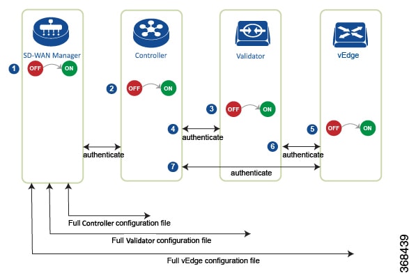
you must install a signed certificate on the router. The signed certificates are generated based on the router's serial number, and they are used to authorize the router to participate in the overlay network.

Starting from Releases 17.1, the Cisco SD-WAN Manager can act as a Certificate Authority (CA), and in this role it can automatically generate and install signed certificates on vEdge Cloud routers. You can also use another CA and then install the signed certificate manually. For Releases 16.3 and earlier, you manually install signed Symantec certificates on vEdge Cloud routers.

To install signed certificates:

  1. Retrieve the vEdge authorized serial number file. This file contains the serial numbers of all the vEdge routers that are allowed to join the overlay network.

  2. Upload the vEdge authorized serial number file to Cisco SD-WAN Manager.

  3. Install a signed certificate on each vEdge Cloud router.

Retrieve vEdge Authorized Serial Number File

  1. Go to http://viptela.com/support/ and log in.

  2. Click Downloads.

  3. Click My Serial Number Files. The screen displays the serial number files. Starting from Releases 17.1, the filename extension is .viptela. For Releases 16.3 and earlier, the filename extension is .txt.

  4. Click the most recent serial number file to download it.

Upload vEdge Authorized Serial Number File

  1. From the Cisco SD-WAN Manager menu, select Configuration > Devices.

  2. Click vEdge List, and select Upload vEdge List.

  3. In the Upload vEdge window:

    1. Click Choose File, and select the vEdge authorized serial number file you downloaded from Cisco.

    2. To automatically validate the vEdge routers and send their serial numbers to the controllers, click and select the checkbox Validate the Uploaded vEdge List and Send to Controllers. If you do not select this option, you must individually validate each router in the Configuration > Certificates > vEdge List page.

  4. Click Upload.

During the process of uploading the vEdge authorized serial number file, the Cisco SD-WAN Manager generates a token for each vEdge Cloud router listed in the file. This token is used as a one-time password for the router. The Cisco SD-WAN Manager sends the token to the Cisco SD-WAN Validator and the Cisco SD-WAN Controller.

After the vEdge authorized serial number file has been uploaded, a list of vEdge routers in the network is displayed in the vEdge Routers Table in the Configuration > Devices page, with details about each router, including the router's chassis number and its token.

Install Signed Certificates in Releases 17.1 and Later

Starting from Releases 17.1, to install a signed certificates on a vEdge Cloud router, you first generate and download a bootstrap configuration file for the router. This file contains all the information necessary to allow the Cisco SD-WAN Manager to generate a signed certificate for the vEdge Cloud router. You then copy the contents of this file into the configuration for the router's VM instance. For this method to work, the router and the Cisco SD-WAN Manager must both be running Release 17.1 or later. Finally, you download the signed certificate to the router. You can configure the Cisco SD-WAN Manager to do this automatically or manually.

The bootstrap configuration file contains the following information:

  • UUID, which is used as the router's chassis number.

  • Token, which is a randomly generated one-time password that the router uses to authenticate itself with the Cisco SD-WAN Validator and the Cisco SD-WAN Manager.

  • IP address or DNS name of the Cisco SD-WAN Validator.

  • Organization name.

    Starting from Cisco Catalyst SD-WAN Manager Release 20.12.1 you cannot include a comma in the Organization Name field of the bootstrap configuration file.

  • If you have already created a device configuration template and attached it to the vEdge Cloud router, the bootstrap configuration file contains this configuration. For information about creating and attaching a configuration template, see Create Configuration Templates for a vEdge Router .

You can generate a bootstrap configuration file that contains information for an individual router or for multiple routers.

Starting from Releases 17.1, you can also have Symantec generate signed certificates that you install manually on each router, as described later in this article, but this method is not recommended.

Configure the Cisco Catalyst SD-WAN Validator and Organization Name

Before you can generate a bootstrap configuration file, you must configure the Cisco SD-WAN Validator DNS name or address and your organization name:

  1. From the Cisco SD-WAN Manager menu, select Administration > Settings.

  2. Click Validator. ( click Edit.)

  3. In the DNS/IP Address: Port field, enter the DNS name or IP address of the Cisco SD-WAN Validator.

  4. Click Save.

  5. Verify the orgnization name. This name must be identical to that configured on the Cisco SD-WAN Validator. (If your are using Cisco Catalyst SD-WAN Manager Release 20.12.1 or earlier, to verify Organization Name, click View.

    Starting from Cisco Catalyst SD-WAN Manager Release 20.12.1, the system Organization Name cannot contain a comma. Comma is not allowed during the device configuration.

  6. Click Save.

Configure Automatic or Manual vEdge Cloud Authorization

Signed certificates must be installed on each vEdge cloud router so that the router is authorized to participate in the overlay network. You can use the Cisco SD-WAN Manager as the CA to generate and install the signed certificate, or you can use an enterprise CA to install the signed certificate.

It is recommended that you use the Cisco SD-WAN Manager as a CA. In this role, Cisco SD-WAN Manager automatically generates and installs a signed certificate on the vEdge Cloud router. Having Cisco SD-WAN Manager act as a CA is the default setting. You can view this setting in the WAN vEdge Cloud Certificate Authorization, on the Cisco SD-WAN Manager Administration > Settings page.

To use an enterprise CA for generating signed certificates for vEdge Cloud routers:

  1. From the Cisco SD-WAN Manager menu, select Administration > Settings.

  2. Click WAN Edge Cloud Certificate Authorization and select Manual.

  3. Click Save.

Generate a Bootstrap Configuration File


Note


In Cisco SD-WAN Release 20.5.1, the cloud-init bootstrap configuration that you generate for the Cisco vEdge Cloud router cannot be used for deploying Cisco vEdge Cloud router 20.5.1. However, you can use the bootstrap configuration for deploying Cisco vEdge Cloud router 20.4.1 and the earlier versions.


To generate a bootstrap configuration file for a vEdge Cloud router:

  1. From the Cisco SD-WAN Manager menu, select Configuration > Devices.

  2. To generate a bootstrap configuration file for one or multiple vEdge Cloud routers:

    1. Click WAN Edge List, select Export Bootstrap Configuration.

    2. In the Generate Bootstrap Configuration field, select the file format:

      • For a vEdge Cloud router on a KVM hypervisor or on an AWS server, select Cloud-Init to generate a token, Cisco SD-WAN Validator IP address, vEdge Cloud router UUID, and organization name.

        Starting from Cisco Catalyst SD-WAN Manager Release 20.12.1, the system Organization Name cannot contain a comma. Comma is not allowed during the device configuration.

      • For a vEdge Cloud router on a VMware hypervisor, select Encoded String to generate an encoded string.

    3. From the Available Devices column, select one or more routers.

    4. Click the arrow pointing to right to move the selected routers to Selected Devices column.

    5. Click Generate Generic Configuration. The bootstrap configuration is downloaded in a .zip file, which contains one .cfg file for each router.

  3. To generate a bootstrap configuration file individually for each vEdge Cloud router:

    1. Click WAN Edge List, select the desired vEdge Cloud router.

    2. For the desired vEdge Cloud router, click ..., and select Generate Bootstrap Configuration.

    3. In the Generate Bootstrap Configuration window, select the file format:

      • For a vEdge Cloud router on a KVM hypervisor or on an AWS server, select Cloud-Init to generate a token, Cisco SD-WAN Validator IP address, vEdge Cloud router UUID, and organization name.

      • For a vEdge Cloud router on a VMware hypervisor, select Encoded String to generate an encoded string.


      Note


      Beginning with Cisco vManage Release 20.7.1, there is an option available when generating a bootstrap configuration file for a Cisco vEdge device, enabling you generate two different forms of the bootstrap configuration file.

      • If you are generating a bootstrap configuration file for a Cisco vEdge device that is using Cisco Catalyst SD-WAN Release 20.4.x or earlier, then check the The version of this device is 20.4.x or earlier check box.

      • If you are generating a bootstrap configuration for a Cisco vEdge device that is using Cisco SD-WAN Release 20.5.1 or later, then do not use the check box.


    4. Click Download to download the bootstrap configuration. The bootstrap configuration is downloaded in a .cfg file.

    Then use the contents of the bootstrap configuration file to configure the vEdge Cloud router instance in AWS, ESXi, or KVM. For example, to configure a router instance in AWS, paste the text of the Cloud-Init configuration into the User data field:

By default, the ge0/0 interface is the router's tunnel interface, and it is configured as a DHCP client. To use a different interface or to use a static IP address, and if you did not attach a device configuration template to the router, change the vEdge Cloud router's configuration from the CLI. See Configuring Network Interfaces.

Install the Certificate on the vEdge Cloud Router

If you are using automated vEdge Cloud certificate authorization, which is the default, after you configure the vEdge Cloud router instance, Cisco SD-WAN Manager automatically installs a certificate on the router and the router's token changes to its serial number. You can view the router's serial number in the Configuration > Devices page. After the router's control connections to the Cisco SD-WAN Manager come up, any templates attached to the router are automatically pushed to the router.

If you are using manual vEdge Cloud certificate authorization, after you configure the vEdge Cloud router instance, follow this procedure to install a certificate on the router:

  1. Install the enterprise root certificate chain on the router:

    vEdge# request root-cert-chain install filename [vpn vpn-id] 

    Then, Cisco SD-WAN Manager generates a CSR.

  2. Download the CSR:

    1. From the Cisco SD-WAN Manager menu, select Configuration > Certificates.

    2. For the selected vEdge Cloud router for which to sign a certificate, click ... and select View CSR.

    3. To download the CSR, click Download.

  3. Send the certificate to a third-party signing authority, to have them sign it.

  4. Import the certificate into the device:

    1. From the Cisco SD-WAN Manager menu, select Configuration > Certificates.

    2. Click Controllers, and select Install Certificate.

    3. In the Install Certificate page, paste the certificate into the Certificate Text field, or click Select a File to upload the certificate in a file.

    4. Click Install.

  5. Issue the following REST API call, specifying the IP address of your Cisco SD-WAN Manager:

    https://vmanage-ip-address/dataservice/system/device/sync/rootcertchain

Create the vEdge Cloud Router Bootstrap Configuration from the CLI

It is recommended that you generate the vEdge Cloud router's bootstrap configuration using Cisco SD-WAN Manager. If, for some reason, you do not want to do this, you can create the bootstrap configuration using the CLI. With this process, you must still, however, use Cisco SD-WAN Manager. You collect some of this information for the bootstrap configuration from Cisco SD-WAN Manager, and after you have created the bootstrap configuration, you use Cisco SD-WAN Manager to install the signed certificate on the router.

Installing signed certificates by creating a bootstrap configuration from the CLI is a three-step process:

  1. Edit the router's configuration file to add the DNS name or IP address of the Cisco SD-WAN Validator and your organization name.

  2. Send the router's chassis and token numbers to Cisco SD-WAN Manager.

  3. Have Cisco SD-WAN Manager authenticate the vEdge Cloud router and install the signed certificate on the router.

To edit the vEdge Cloud router's configuration file from the CLI:

  1. Open a CLI session to the vEdge Cloud router via SSH. To do this in Cisco SD-WAN Manager, select Tools > SSH Terminal page, and select the desired router.

  2. Log in as the user admin, using the default password, admin. The CLI prompt is displayed.

  3. Enter configuration mode:

    vEdge# config
    vEdge(config)#
  4. Configure the IP address of the Cisco SD-WAN Validator or a DNS name that points to the Cisco SD-WAN Validator. The Cisco SD-WAN Validator's IP address must be a public IP address:

    vEdge(config)# system vbond (dns-name | ip-address)
  5. Configure the organization name:

    vEdge(config-system)# organization-name name
  6. Commit the configuration:

    vEdge(config)# commit and-quit
    vEdge#

To send the vEdge Cloud router's chassis and token numbers to Cisco SD-WAN Manager:

  1. Locate the vEdge Cloud router's token and chassis number:

    1. From the Cisco SD-WAN Manager menu, select Configuration > Devices.

    2. Click WAN Edge List, locate the vEdge Cloud router.

    3. Make a note of the values in the vEdge Cloud router's Serial No./Token and Chassis Number columns.

  2. Send the router's bootstrap configuration information to Cisco SD-WAN Manager:

    vEdge# request vedge-cloud activate chassis-number chassis-number token token-number

Issue the show control local-properties command on the router to verify the Cisco SD-WAN Validator IP address, the organization name the chassis number, and the token. You can also verify whether the certificate is valid.

Finally, have Cisco SD-WAN Manager authenticate the vEdge Cloud router and install the signed certificate on the router.

If you are using automated vEdge Cloud certificate authorization, which is the default, the Cisco SD-WAN Manager uses the chassis and token numbers to authenticate the router. Then, Cisco SD-WAN Manager automatically installs a certificate on the router and the router's token changes to a serial number. You can display the router's serial number in the Configuration > Devices page. After the router's control connections to Cisco SD-WAN Manager come up, any templates attached to the router are automatically pushed to the router.

If you are using manual vEdge Cloud certificate authorization, after you configure the vEdge Cloud router instance, follow this procedure to install a certificate on the router:

  1. Install the enterprise root certificate chain on the router:

    vEdge# request root-cert-chain install filename [vpn vpn-id] 

    After you install the root chain certificate on the router, and after Cisco SD-WAN Manager receives the chassis and token numbers, Cisco SD-WAN Manager generates a CSR.

  2. Download the CSR:

    1. From the Cisco SD-WAN Manager menu, select Configuration > Certificates.

    2. For the selected vEdge Cloud router for which to sign a certificate, click ... and select View CSR.

    3. To download the CSR, click Download.

  3. Send the certificate to a third-party signing authority, to have them sign it.

  4. Import the certificate into the device:

    1. From the Cisco SD-WAN Manager menu, select Configuration > Certificates.

    2. Click Controllers and select Install Certificate.

    3. In the Install Certificate page, paste the certificate into the Certificate Text field, or click Select a File to upload the certificate in a file.

    4. Click Install.

  5. Issue the following REST API call, specifying the IP address of your Cisco SD-WAN Manager:

    https://vmanage-ip-address/dataservice/system/device/sync/rootcertchain

Install Signed Certificates in Releases 16.3 and Earlier

For vEdge Cloud router virtual machine (VM) instances running Releases 16.3 and earlier, when the vEdge Cloud router VM starts, it has a factory-default configuration, but is unable to join the overlay network because no signed certificate is installed. You must install a signed Symantec certificate on the vEdge Cloud router so that it can participate in the overlay network.

To generate a certificate signing request (CSR) and install the signed certificate on the vEdge Cloud router:

  1. Log in to the vEdge Cloud router as the user admin, using the default password, admin. If the vEdge Cloud router is provided through AWS, use your AWS key pair to log in. The CLI prompt is displayed.

  2. Generate a CSR for the vEdge Cloud router:

    vEdge# request csr upload path

    path is the full path and filename where you want to upload the CSR. The path can be in a directory on the local device or on a remote device reachable through FTP, HTTP, SCP, or TFTP. If you are using SCP, you are prompted for the directory name and filename; no file path name is provided. When prompted, enter and then confirm your organization name. For example:

    vEdge# request csr upload home/admin/vm9.csr
    Uploading CSR via VPN 0
    Enter organization name            : Cisco
    Re-enter organization name         : Cisco
    Generating CSR for this vEdge device
    ........[DONE]
    Copying ... /home/admin/vm9.csr via VPN 0
    CSR upload successful
  3. Log in to the Symantec Certificate Enrollment portal:

    https://certmanager.<wbr/>websecurity.symantec.com/<wbr/>mcelp/enroll/index?jur_hash=<wbr/>f422d7ceb508a24e32ea7de4f78d37<wbr/>f8

  4. In the Select Certificate Type drop-down, select Standard Intranet SSL and click Go. The Certificate Enrollment page is displayed. Cisco Catalyst SD-WAN uses the information you provide on this form to confirm the identity of the certificate requestor and to approve your certificate request. To complete the Certificate Enrollment form:

    1. In the Your Contact Information section, specify the First Name, Last Name, and Email Address of the requestor.

    2. In the Server Platform and Certificate Signing section, select Apache from the Select Server Platform drop-down. In the Enter Certificate Signing Request (CSR) box, upload the generated CSR file, or copy and paste the contents of the CSR file. (For details about how to do this, log in to support.viptela.com. Click Certificate, and read the Symantec certificate instructions.)

    3. In the Certificate Options section, enter the validity period for the certificate.

    4. In the Challenge Phrase section, enter and then re-enter a challenge phrase. You use the challenge phrase to renew, and, if necessary, to revoke a certificate on the Symantec Customer Portal. It is recommended that you specify a different challenge phrase for each CSR.

    5. Accept the Subscriber Agreement. The system generates a confirmation message and sends an email to the requestor confirming the certificate request. It also sends an email to the Cisco to approve the CSR.

  5. After Cisco approves the CSR, Symantec sends the signed certificate to the requestor. The signed certificate is also available through the Symantec Enrollment portal.

  6. Install the certificate on the vEdge Cloud router:

    vEdge# request certificate install filename [vpn vpn-id] 

    The file can be in your home directory on the local device, or it can be on a remote device reachable through FTP, HTTP, SCP, or TFTP. If you are using SCP, you are prompted for the directory name and filename; no file path name is provided.

  7. Verify that the certificate is installed and valid:

    vEdge# show certificate validity 

After you have installed the certificate on the vEdge Cloud router, the Cisco SD-WAN Validator is able to validate and authenticate the router, and the router is able to join the overlay network.

What's Next

See Send vEdge Serial Numbers to the Controller Devices.

Send Router Serial Numbers to the Controller Devices

Table 9. Feature History
Feature Name Release Information Description
Device Onboarding Enhancement

Cisco IOS XE Catalyst SD-WAN Release 17.3.1a

Cisco vManage Release 20.3.1

This feature provides an enhancement to onboard your device to Cisco SD-WAN Manager by directly uploading a .csv file.

Only authorized routers can join the overlay network. The controller devices Cisco SD-WAN Manager, Cisco SD-WAN Controllers and Cisco SD-WAN Validators learn which routers are authorized to join the overlay network from the router-authorized serial number file. This is a file that you receive from Cisco. The router authorized serial number file lists the serial numbers and corresponding chassis numbers for all authorized routers. Upload the file to one of the Cisco SD-WAN Manager in your network, and it then distributes the file to the controllers.

When you upload the router serial number file, you can place the routers in one of these states:

  • Invalid: When you power on the routers, they are not authorized to join the overlay network.

  • Staging: When you power on the routers, they are validated and authorized to join the overlay network, and can establish connections only to the control plane. Over the control plane, the routers receive their configuration from Cisco SD-WAN Manager. However, the routers are unable to establish data plane connections, so they cannot communicate with other routers in the network. The Staging state is useful when you are preparing routers at one location and then sending them to different sites for installation. Once the routers reach their final destination, you change their state from Staging to Valid, to allow the routers to establish data plane connections and to fully join the overlay network.

  • Valid: When you power on the routers, they are validated and authorized to join the overlay network, and they are able to establish both control plane and data plane connections in the network. Over the control plane, the routers receive their configuration from Cisco SD-WAN Manager. Over the data plane, they are able to communicate with other routers. The Valid state is useful when the routers are being installed at their final destination.


Note


To successfully send a router serial number file to Cisco Catalyst SD-WAN Manager in Cisco vManage Release 20.10.1 and earlier, ensure that the file is installed in /home/admin or /home/vmanage-admin. Using credentials other than admin or vmanage-admin to send a router serial number file will result in an error.


How to Upload a Router Authorized Serial Number File

The following sections describe how to upload the router authorized serial number file to Cisco SD-WAN Manager and distribute the file to all the overlay network controllers.

Enable PnP Connect Sync (Optional)

To sync the uploaded device to your Smart Account or Virtual Account and for your device to reflect on the PnP (Plug and Play) Connect portal, when an unsigned .csv file is uploaded through Cisco SD-WAN Manager, enable the PnP Connect Sync.

Ensure you have an active connection to the PnP (Plug and Play) Connect portal and an active Smart Account and Virtual Account. You have to also use a CCO ID that is associated as the Smart Account or Virtual Account admin of the account, on PnP Connect portal.


Note


PnP Connect Sync is only applicable to .csv file upload. It does not affect the .viptela file (which is downloaded from the PnP Connect portal) upload process.

Note


You will be allowed to enable PnP Connect Sync only once you enter the Smart Account credentials.

To enable the PnP Connect Sync:

  1. From the Cisco SD-WAN Manager menu, select Administration > Settings.

  2. Click Smart Account Credentials. (If you are using Cisco Catalyst SD-WAN Manager Release 20.12.1 and earlier, click Edit..)

  3. Enter Username and Password and click Save.

  4. Click PnP Connect Sync. (If you are using Cisco Catalyst SD-WAN Manager Release 20.12.1 and earlier, click Edit..)

  5. Click Enabled and click Save.

Place Routers in Valid State

Perform the following task to place the routers in the Valid state so that they can establish control and data plane connections and can receive their configurations from the Cisco SD-WAN Manager:

  1. From the Cisco SD-WAN Manager menu, select Configuration > Devices.

  2. Click WAN Edge List and click Upload WAN Edge List.

  3. You can upload WAN Edge devices in the following two ways:

    • Upload a signed file (.viptela file). You can download this .viptela file from the Plug and Play Connect portal.

    • Starting from Cisco vManage Release 20.3.1, you can upload an unsigned file (.csv file). This enhancement is only applicable when you add hardware platforms on-demand onto Cisco SD-WAN Manager. To upload the .csv file this:

      1. Click Sample CSV. An excel file will be downloaded.

      2. Open the downloaded .csv file. Enter the following parameters:

        • Chassis number

        • Product ID (mandatory for Cisco vEdge devices, blank value for all other devices)

        • Serial number

        • SUDI serial

        Either the Serial number or SUDI number is mandatory for Cisco IOS XE Catalyst SD-WAN devices, along with chassis number. Cisco ASR1002-X is an exception and does not need Serial or SUDI numbers, it can be onboarded with only the chassis number on the .csv file.

      3. To view your device details in Cisco SD-WAN Manager, go to Tools > SSH Terminal. Choose your device and use one of the following command-

        show certificate serial (for vEdge devices)

        show sdwan certificate serial (for Cisco IOS XE Catalyst SD-WAN devices)

      4. Enter the specific device details in the downloaded .csv file.

  4. To upload the .viptela or .csv file on Cisco SD-WAN Manager click Choose file and upload the file that contains the product ID, serial number and chassis number of your device.


    Note


    If you have enabled PnP Sync Connect, the .csv file can contain upto 25 devices. If you have more than 25 devices, you can split them and upload multiple files.
  5. Check the check box next to Validate the uploaded vEdge List and send to controllers.

  6. Click Upload.

  7. You should now see your device listed in the table of devices.

    If you have enabled the PnP Sync Connect previously, your device will also reflect on the PnP Portal.

A list of routers in the network is displayed, showing detailed information about each router. To verify that the routers are in the Valid state, select Configuration > Certificates.

Place Routers in Invalid State

To upload the authorized serial number file to the Cisco SD-WAN Manager, but place the routers in Invalid state so that they cannot establish control plane or data plane connections and cannot receive their configurations from Cisco SD-WAN Manager:

  1. From the Cisco SD-WAN Manager menu, select Configuration > Devices.

  2. Click WAN Edge List and click Upload WAN Edge List.

  3. In the Upload WAN Edge List dialog box, choose the file to upload.

  4. To upload the router serial number file to Cisco SD-WAN Manager, click Upload.

A list of routers in the network is displayed, showing detailed information about each router. To verify that the routers are in the Invalid state, from the Cisco SD-WAN Manager menu, select Configuration > Certificates.

Place Routers in Staging State

To move the routers from the Invalid state to the Staging state and then send the serial number file to the controllers, follow the steps below. In the Staging state, the routers can establish control plane connections, over which they receive their configurations from Cisco SD-WAN Manager. However, the routers cannot establish data plane connections.

  1. From the Cisco SD-WAN Manager menu, select Configuration > Certificates.

  2. Click WAN Edge List.

  3. In the Validate column, click Staging for each router.

  4. Click Send to Controller.

  5. When you are ready to have the router join the data plane in the overlay network, in the Validate column, click Valid for each router, and then click Send to Controller. Placing the routers in the Valid state allows them to establish data plane connections and to communicate with other routers in the overlay network.

Configure the vEdge Routers

Once you have set up and started the virtual machines (VMs) for the vEdge Cloud routers and set up and started the hardware vEdge routers in your overlay network, they come up with a factory-default configuration.


Note


Log In to a Device for the First Time: When you first deploy a Cisco Catalyst SD-WAN overlay network, log in to the Cisco SD-WAN Validator, Cisco SD-WAN Manager, and Cisco SD-WAN Controller to manually create the device's initial configuration. Routers are shipped with a factory default configuration. If you choose to modify this configuration manually, log in through the router's console port.


For the overlay network to be operational and for the vEdge routers to be able to participate in the overlay network, you must do the following:

  • Configure a tunnel interface on at least one interface in VPN 0. This interface must be connected to a WAN transport network that is accessible to all Cisco vEdge devices. VPN 0 carries all control plane traffic between the Cisco vEdge devices in the overlay network.

  • Ensure that the Overlay Management Protocol (OMP) is enabled. OMP is the protocol responsible for establishing and maintaining the Cisco Catalyst SD-WAN control plane. It is enabled by default, and you cannot disable it. If you edit the configuration from the CLI, do not remove the omp configuration command.

  • Ensure that BFD is enabled. BFD is the protocol that the transport tunnels on vEdge routers use for transmitting data traffic through the overlay network. BFD is enabled by default, and cannot be disabled. If you edit the configuration from the CLI, do not remove the bfd color command.

  • Configure the IP address of DNS name of your network's Cisco SD-WAN Validator.

  • Configure the IP address of the router.


    Note


    The DNS cache timeout should be proportional to the number of Cisco SD-WAN Validator IP addresses that DNS has to resolve, otherwise the control connection for Cisco SD-WAN Manager may not occur during a link failure. This is because, when there are more than six IP addresses (this is the recommended number since the default DNS cache timeout is currently two minutes) to be checked, the DNS cache timer expires even as the highest preferred interface tries all Cisco SD-WAN Validator IP addresses, before failing over to a different color. For instance, it takes about 20 seconds to attempt to connect to one IP address. So, if there are eight IP addresses to be resolved, the DNS cache timeout should be 20*8=160 seconds or three minutes.

You should also assign a system IP address to each vEdge router. This address, which is similar to the router ID on non-Cisco vEdge devices, is a persistent address that identifies the router independently of any interface addresses. The system IP is a component of the device's TLOC address. Setting the system IP address for a device allows you to renumber interfaces as needed without affecting the reachability of the Cisco vEdge device. Control traffic over secure DTLS or TLS connections between Cisco SD-WAN Controllers and vEdge routers and between Cisco SD-WAN Controllers and Cisco SD-WAN Validators is sent over the system interface identified by the system IP address. In the transport VPN (VPN 0), the system IP address is used as the loopback address of the device. You cannot use the same address for another interface in VPN 0.

You can also configure other features and functions required for your network topology.

You configure vEdge routers by creating configuration templates on the Cisco SD-WAN Manager. For each configuration templates, you create one or more feature templates, which you then consolidate into a vEdge router device template. You then attach the device template to a vEdge router. When the vEdge router joins the overlay network, the Cisco SD-WAN Manager automatically pushes the configuration template to the router.

It is strongly recommended that you create the full configuration for vEdge routers by creating configuration templates on the Cisco SD-WAN Manager. When the Cisco SD-WAN Manager discovers a router in the overlay network, it pushes the appropriate configuration template to the device. The configuration parameters in the configuration template overwrite the initial configuration.

Create Configuration Templates for the vEdge Routers

To create vEdge configuration templates, first create feature templates:

  1. From the Cisco SD-WAN Manager menu, choose Configuration > Templates.

  2. Click Feature Templates.


    Note


    In Cisco vManage Release 20.7.x and earlier releases, Feature Templates is called Feature.


  3. Click Add Template.

  4. In the left pane, select vEdge Cloud or a router model.

  5. In the right pane, select the System feature template. Configure the following parameters:

    1. Template Name

    2. Description

    3. Site ID

    4. System IP

    5. Timezone

    6. Hostname

    7. Console baud rate (vEdge hardware routers only)

    8. GPS location

  6. Click Save to save the System template.

  7. In the right pane, select VPN-Interface-Ethernet feature template. Configure the following parameters:

    1. Template Name

    2. Description

    3. Shutdown No

    4. Interface name

    5. IPv4 address (static or DHCP)

    6. IPv6 address (static of DHCPv6), if desired (in Releases 16.3 and later)

    7. Tunnel interface (for VPN 0), color, encapsulation, and services to allow.

  8. Click Save to save the VPN-Interface Ethernet template.

  9. In the right pane, select other templates to configure any desired features. Save each template when you complete the configuration. For information about configuration cellular parameters for vEdge 100m and vEdge 100wm routers, see the next section in this article.

For information about configuration templates and parameters, see the Cisco SD-WAN Manager configuration help articles for your software release.

Next, create a device template that incorporates all the feature templates for the vEdge router:

  1. From the Cisco SD-WAN Manager menu, choose Configuration > Templates.

  2. Click Device Templates.


    Note


    In Cisco vManage Release 20.7.x and earlier releases, Device Templates is called Device.


  3. From the Create Template drop-down list, select From Feature Template.

  4. From the Device Model drop-down, select the type of device for which you are creating the device template. Cisco SD-WAN Manager displays the feature templates for the device type you selected. Required templates are indicated with an asterisk (*).

  5. Enter a name and description for the device template. These fields are mandatory. The template name cannot contain special characters.

  6. In the Transport & Management VPN section, under VPN 0, from the drop-down list of available templates, select the desired feature template. The list of available templates shows the ones that you have previously created.

  7. To include additional feature templates in the device template, in the remaining sections, select the feature templates in turn, and from the drop-down list of available templates, select the desired template. The list of available templates are the ones that you have previously created. Ensure that you select templates for all mandatory feature templates and for any desired optional feature templates.

  8. Click Create to create the device template.

To attach a device template to a device:

  1. From the Cisco SD-WAN Manager menu, choose Configuration > Templates.

  2. Click Device Templates, and select a template.


    Note


    In Cisco vManage Release 20.7.x and earlier releases, Device Templates is called Device.


  3. For the selected template, click ... and select Attach Device.

  4. In the Attach Device window, either search for a device or select a device from the Available Device(s) column.

  5. Click the arrow pointing right to move the device to the Selected Device(s) column on the right.

  6. Click Attach.

When Cisco SD-WAN Manager discovers that the vEdge router has joined the overlay network, it pushes the configuration template to the router.

Configuring Cellular Routers

For vEdge 100m and vEdge 100wm routers, you configure cellular interface parameters on the VPN-Interface-Cellular feature template. In this template, the default Profile ID is 0, which enables automatic profile selection. The automatic profile uses the Mobile Country Code/Mobile Network Code (MCC/MNC) values on the router's SIM card. Profile 0 enables the cellular router to automatically join the overlay network during the Cisco Catalyst SD-WAN ZTP automatic provisioning process .

If your MCC/MNC is not supported, the automatic profile selection process fails, and the ZTP process is unable to autodetect the router. In this case, you must configure a cellular profile as follows:

  1. In the right pane, select the Cellular Profile feature template.

  2. Set the Profile ID to a value from 1 through 15, and configure the desired cellular parameters.

  3. Save the Cellular Profile feature template.

  4. In the right pane, select the VPN-Interface-Cellular template.

  5. Select the Profile ID you configured in Step 2, and for Shutdown, click Yes.

  6. Save the VPN-Interface-Cellular feature template.

  7. Include the Cellular Profile and VPN-Interface Cellular templates in a device template.

  8. Attach the device template to the vEdge router to activate the MCC/MCN.

  9. In the right pane, select the VPN-Interface-Cellular template.

  10. For Shutdown click No, to enable the cellular interface.

  11. Save the VPN-Interface-Cellular feature template.

  12. Repush the device template to the vEdge router. This is the device template that you pushed in Step 8.

Configure the vEdge Routers from the CLI

Normally, you create vEdge router configurations using Cisco SD-WAN Manager configuration templates. However, in some situations, such as network test and proof-of-concept (POC) environments, you might want to configure vEdge routers manually, either to speed up the configuration process or because your test environment does not include Cisco SD-WAN Manager. In such situations, you can configure vEdge routers from the router's CLI.


Note


If you configure a vEdge router manually from the CLI and then the router later becomes managed by a Cisco SD-WAN Manager, when the Cisco SD-WAN Manager discovers the router, it pushes the router's configuration from the Cisco SD-WAN Manager server to the router, overwriting the existing configuration.


For vEdge Cloud routers, use SSH to open a CLI session to the router. For hardware vEdge routers, connect to the router via the management console.

Configure Minimum Parameters from the CLI

To create the initial configuration on a Cisco vEdge device from a CLI session:

  1. Open a CLI session to the Cisco vEdge device via SSH or the console port.

  2. Log in as the user admin, using the default password, admin. The CLI prompt is displayed.

  3. Enter configuration mode:

    vEdge# config 
    vEdge(config)#
  4. Configure the hostname:

    vEdge(config)# system host-name hostname

    Configuring the hostname is optional, but is recommended because this name in included as part of the prompt in the CLI and it is used on various Cisco SD-WAN Manager pages to refer to the device.

  5. Configure the system IP address. Starting from Releases 16.3 and later, the IP address can be an IPv4 or an IPv6 address. In earlier releases, it must be an IPv4 address.

    vEdge(config-system)#system-ip ip-address

    Cisco SD-WAN Manager uses the system IP address to identify the device so that the NMS can download the full configuration to the device.

  6. Configure the numeric identifier of the site where the device is located:

    vEdge(config-system)# site-id site-id
  7. Configure the organization name:

    vEdge(config-system)# organization-name organization-name
  8. Configure the IP address of the Cisco SD-WAN Validator or a DNS name that points to the Cisco SD-WAN Validator. The IP address of the Cisco SD-WAN Validator must be a public IP address, to allow all Cisco vEdge devices in the overlay network to reach the Cisco SD-WAN Validator:

    vEdge(config-system)# vbond (dns-name | ip-address)
  9. Configure a time limit for confirming that a software upgrade is successful:

    vEdge(config-system)# upgrade-confirm minutes

    The time can be from 1 through 60 minutes. If you configure this time limit, when you upgrade the software on the device, the Cisco SD-WAN Manager (when it comes up) or you must confirm that a software upgrade is successful within the configured number of minutes. If the device does not received the confirmation within the configured time, it reverts to the previous software image.

  10. Change the password for the user "admin":

    vEdge(config-system)# user admin password password

    The default password is "admin".

  11. Configure an interface in VPN 0 to be used as a tunnel interface. VPN 0 is the WAN transport VPN, and the tunnel interface carries the control traffic among the devices in the overlay network. For vEdge Cloud routers, the interface name has the format eth number. For hardware vEdge routers, the interface name has the format ge slot / port. You must enable the interface and configure its IP address, either as a static address or as a dynamically assigned address received from a DHCP server. Starting from Releases 16.3 and later, the IP address can be an IPv4 or an IPv6 address, or you can configure both to enable dual-stack operation. In earlier releases, it must be an IPv4 address.

    ​vEdge(config)# vpn 0
    vEdge(config-vpn-0)# interface interface-name
    vEdge(config-interface)# (ip dhcp-client | ip address prefix/length) 
    vSmart(config-interface)# (ipv6 address ipv6-prefix/length | ipv6 dhcp-client [dhcp-distance number | dhcp-rapid-commit]) 
    vEdge(config-interface)# no shutdown 
    vEdge(config-interface)# tunnel-interface

    Note


    You must configure a tunnel interface on at least one interface in VPN 0 in order for the overlay network to come up and for the Cisco SD-WAN Manager to be able to participate in the overlay network. This interface must connect to a WAN transport network that is accessible by all Cisco vEdge devices. VPN 0 carries all control plane traffic among the Cisco vEdge devices in the overlay network.


  12. Configure a color for the tunnel to identify the type of WAN transport. You can use the default color (default), but you can also configure a more appropriate color, such as mpls or metro-ethernet, depending on the actual WAN transport.

    vEdge(config-tunnel-interface)# color color

  13. Configure a default route to the WAN transport network:

    vEdge(config-vpn-0)# ip route 0.0.0.0/0 next-hop
  14. Commit the configuration:

    vEdge(config)# commit and-quit
    vEdge#
  15. Verify that the configuration is correct and complete:

    vEdge# show running-config

After the overlay network is up and operational, create a vEdge configuration template on the Cisco SD-WAN Manager that contains the initial configuration parameters. Use the following Cisco SD-WAN Manager feature templates:

  • System feature template to configure the hostname, system IP address, and Cisco SD-WAN Validator functionality.

  • AAA feature template to configure a password for the "admin" user.

  • VPN-Interface-Ethernet feature template to configure the interface in VPN 0.

In addition, it is recommended that you configure the following general system parameters:

  • From the Cisco SD-WAN Manager menu, select Administration > Settings and configure Organization name.

  • From the Cisco SD-WAN Manager menu, select Configuration > Templates. For the NTP and System feature configuration templates, configure Timezone, NTP servers, and device physical location.

    • For the Banner feature configuration template, configure Login banner.

    • For the Logging feature configuration template, configure Logging parameters.

    • For the AAA feature configuration template, configure AAA, and RADIUS and TACACS+ servers.

    • For the SNMP feature configuration template, configure SNMP.

Sample Initial CLI Configuration

Below is an example of a simple configuration on a vEdge router. Note that this configuration includes a number of settings from the factory-default configuration and shows a number of default configuration values.

vEdge# show running-config
system
 host-name         vEdge
 gps-location latitude 40.7127837
 gps-location longitude -74.00594130000002
 system-ip         172.16.251.20
 site-id           200
 max-controllers   1
 organization-name "Cisco"
 clock timezone America/Los_Angeles
 upgrade-confirm   15
 vbond 184.122.2.2
 aaa
  auth-order local radius tacacs
  usergroup basic
   task system read write
   task interface read write
  !
  usergroup netadmin
  !
  usergroup operator
   task system read
   task interface read
   task policy read
   task routing read
   task security read
  !
  user admin
   password encrypted-password
  !
 !
 logging
  disk
   enable
  !
 !
 ntp
  keys
   authentication 1 md5 $4$L3rwZmsIic8zj4BgLEFXKw== 
   authentication 2 md5 $4$LyLwZmsIif8BvrJgLEFXKw== 
   authentication 60124 md5 $4$LXbzZmcKj5Bd+/BgLEFXKw==
   trusted 1 2 60124
  !
  server 180.20.1.2
   key              1
   source-interface ge0/3
   vpn              1
   version          4
  exit
 !
 radius
  server 180.20.1.2
   vpn              1 
   source-interface ge0/3
   secret-key       $4$L3rwZmsIic8zj4BgLEFXKw==
  exit
 !
 tacacs
  server 180.20.1.2 
   vpn              1024
   source-interface ge0/3
   secret-key       $4$L3rwZmsIic8zj4BgLEFXKw==
  exit  
 !
!                                                                                                            
omp
 no shutdown
 gradeful-restart
 advertise bgp
 advertise connected
 advertise static
!
security
 ipsec
  authentication-type ah-sha1-hmac sha1-hman
 !
! 
snmp
 no shutdown
 view v2
  oid 1.3.6.1
 !
 community private
  view          v2
  authorization read-only
 !
 trap target vpn 0 10.0.1.1 16662
  group-name     Cisco
  community-name private
 !
 trap group test
  all
   level critical major minor
  exit
 exit
!
vpn 0
 interface ge0/0
  ip address 184.111.20.2/24
  tunnel-interface
   encapsulation ipsec
   color mpls restrict
   no allow-service bgp
   allow-service dhcp
   allow-service dns
   allow-service icmp
   no allow-service sshd
   no allow-service netconf
   no allow-service ntp
   no allow-service ospf
   no allow-service stune
  !
  no shutdown
  bandwidth-upstream   60
  bandwidth-downstream 60
 !
 interface ge0/1
   no shutdown
 !
 interface ge0/2
   no shutdown
 !
 ip route 0.0.0.0/0 184.111.20.1                                                                                        
! 
vpn 1
 router
   bgp 111000
    neighbor 172.16.1.20
     no shutdown
     remote-as 111000
     password  $4$LzLwZj1ApK4zj4BgLEFXKw==
    !
   !
   ospf
    timers spf 200 1000 10000
    area 0
     interface ge0/1
       authentication type message-direct
       authentication message-digest message-digest-key 1 md5 $4$LzLwZj1ApK4zj4BgLEFXKw==
      exit
     exit
   !
 !
!

Enable Data Stream Collection from a WAN Edge Router

By default, collecting streams of data from a network device is not enabled.

To collect data streams from a WAN Edge router in the overlay network, perform the following steps.

Collecting data streams also requires that VPN 512 be configured in your Cisco Catalyst SD-WAN network.

  1. From the Cisco SD-WAN Manager menu, select Administration > Settings.

  2. Click Data Stream. (If you are using Cisco Catalyst SD-WAN Manager Release 20.12.1 or earlier, click Edit.)

  3. Enable Data Stream.

  4. From Cisco vManage Release 20.4.1, choose one of the following IP Address Type options:

    • Transport: Click this option send the data stream to the transport IP address of the Cisco SD-WAN Manager node to which the device is connected.

    • Management: Click this option send the data stream to the management IP address of the Cisco SD-WAN Manager node to which the device is connected.

    • System: Click this option to send the data stream to the internally configured system IP address of theCisco SD-WAN Manager node to which the device is connected.

      In a Cisco SD-WAN Manager cluster deployment, we recommend that you choose System so that the data stream is collected from edge devices that are managed by all Cisco SD-WAN Manager instances in the cluster.

  5. From Cisco vManage Release 20.4.1, perform one of these actions:

    • If you choose Transport as the IP address type, in the Hostname field, enter the public transports IP address that is used to connect to the router.

      You can determine this IP address by using an SSH client to access the router and entering the show interface CLI command.

    • If you choose Management as the IP address type, in the Hostname field, enter the IP address or name of the host to collect the data.

      We recommend that this host is one that is used for out-of-band management and that it is located in the management VPN.

    This Hostname option is dimmed when IP Address Type is System.

  6. In the VPN field, enter the number of the VPN in which the host is located.

    We recommend that this VPN be the management VPN, which is typically VPN 512.

    This VPN option is dimmed when IP Address Type is System.

  7. Click Save.

Prepare Routers for ZTP

Cisco Catalyst SD-WAN provides an automatic provisioning software as a service (SaaS) called zero-touch provisioning (ZTP), which allows hardware vEdge routers to join the overlay network automatically. The ZTP process begins when you power on a hardware vEdge router for the first time.

For the ZTP process to work:

  • The edge or gateway router at the site where the hardware vEdge router is located must be able to reach public DNS servers. We recommend that the router be configured to reach the Google public DNS servers.

  • For Cisco vEdge devices, the edge or gateway router at the site must be able to reachztp.viptela.com.

  • For Cisco IOS XE Catalyst SD-WAN devices, the edge or gateway router at the site must be able to reach ztp. local-domain.

  • A network cable must be plugged into the interface that the hardware router uses for ZTP. These interfaces are:

    • For Cisco vEdge 1000 routers: ge0/0

    • For Cisco vEdge 2000 routers: ge2/0

    • For Cisco vEdge 100 series routers: ge0/4

    • For Cisco IOS XE Catalyst SD-WAN devices, there is no specific interface that is used for connection to the ZTP server. The router attempts to obtain a DHCP IP address on one interface at a time. It uses the first interface on which it obtains the DHCP IP address to resolve the domain name ztp. local-domain to the IP address of the ZTP server.

The ZTP process occurs in the following sequence:

Figure 18. Sequence Flow of the ZTP Process
The figure depicts the occurring sequence of the zero-touch provisioning (ZTP) process.
  1. The hardware router powers up.

  2. The router attempts to contact a DHCP server, sending a DHCP discovery message.

    1. If a DHCP server is present in the network, the router receives a DHCP offer message that contains the IP address of its ZTP interface. Then, the ZTP process continues with Step 3.

    2. For Cisco vEdge devices, and for Cisco IOS XE Catalyst SD-WAN devices from Cisco IOS XE Catalyst SD-WAN Release 17.7.1a, if no DHCP server is present, the router does not receive a DHCP offer. In this situation, the router initiates an automatic IP address detection process (also referred to as auto-IP). This process examines the ARP packets on the subnetwork and, from these packets, it infers the IP address of the ZTP interface. Then, the ZTP process continues with Step 3.

      For Cisco IOS XE Catalyst SD-WAN devices before Cisco IOS XE Catalyst SD-WAN Release 17.7.1a, if no DHCP server is present, the ZTP process does not continue.

  3. The router contacts a DNS server to resolve the hostname ztp.viptela.com (for Cisco vEdge devices) or ztp. local-domain (Cisco IOS XE Catalyst SD-WAN devices) and receives the IP address of the Cisco Catalyst SD-WAN ZTP server

  4. The router connects to the ZTP server. The ZTP server verifies the vEdge router and sends the IP address of the Cisco SD-WAN Validator. This Cisco SD-WAN Validator has the same Organization name as the vEdge router.

  5. The router establishes a transient connection to the Cisco SD-WAN Validator and sends its chassis ID and serial number. (At this point in the ZTP process, the router does not have a system IP address, so the connection is established with a null system IP address.) The Cisco SD-WAN Validator uses the chassis ID and serial number to verify the router. The Cisco SD-WAN Validator then sends the IP address of Cisco SD-WAN Manager to the router.

  6. The router establishes a connection to and is verified by Cisco SD-WAN Manager. Cisco SD-WAN Manager sends the router its system IP address.

  7. The router re-establishes a connection to the Cisco SD-WAN Validator using its system IP address.

  8. The router re-establishes a connection to Cisco SD-WAN Manager using its system IP address.

    For Cisco vEdge devices, if necessary, Cisco SD-WAN Manager pushes the proper software image to the vEdge router. As part of the software image installation, the router reboots.

  9. After the reboot, the router reestablishes a connection to the Cisco SD-WAN Validator, which again verifies the router.

  10. The router establishes a connection to Cisco SD-WAN Manager, which pushes the full configuration to the router. (If the router has rebooted, it re-establishes a connection to Cisco SD-WAN Manager.)

  11. The router joins the organization's overlay network.


Note


For the ZTP process to succeed, Cisco SD-WAN Manager must contain a device configuration template for the vEdge router. If the Cisco SD-WAN Manager instance has no template, the ZTP process fails. Ignore the device-model and ztp-status display in the configuration preview and intent configuration. This information is visible after you push the configuration on device side.

Using ZTP on Non-Wireless Routers

The default configuration that is shipped on non-wireless hardware vEdge routers includes the following commands that allow the ZTP process to occur automatically:

  • system vbond ztp.viptela.com—Configures the initial Cisco SD-WAN Validator to be the Cisco Catalyst SD-WAN ZTP SaaS server.

  • vpn 0 interface ip dhcp-client—Enables DHCP on one of the interfaces in VPN 0, which is the transport interface. Note that the actual interface in the default configuration varies by router model. This interface must be connected to the Internet, MPLS, metro Ethernet, or other WAN network.

Warning: For ZTP to work, do not modify or delete either of these configuration commands before you connect the vEdge router to a WAN.

Using ZTP on Wireless Routers

The vEdge 100m and vEdge 100wm are wireless routers. On these routers, ZTP is supported using both the cellular and the Ethernet interfaces.


Note


In Release 16.3, you cannot use the LTE USB dongle on a vEdge 1000 router for ZTP.

The vEdge 100m router supports software Releases 16.1 and later. If the vEdge 100m router is running Release 16.2.10 or later, we recommend, when performing ZTP, that Cisco SD-WAN Manager also be running Release 16.2.10 or later.

The vEdge 100wm router supports software Releases 16.3 and later.

The default configuration that is shipped on wireless hardware vEdge routers includes the following commands that allow the ZTP process to occur automatically on the cellular interface:

  • system vbond ztp.viptela.com: Configure the initial Cisco SD-WAN Validator to be the Cisco Catalyst SD-WAN ZTP SaaS server.

  • vpn 0 interface cellular0 ip dhcp-client : Enable DHCP on one of the cellular interface called cellular0 in VPN 0, which is the transport interface. This interface must be connected to the cellular network.

  • vpn 0 interface cellular0 technology : Associate a radio access technology (RAT) with the cellular interface. In the default configuration, the RAT is set to lte. For ZTP to work, you must change this value to auto.

  • vpn 0 interface cellular0 profile 0 : Enable automatic profile selection. For firmware-dependent mobile carriers, the automatic profile uses the firmware default values. For other carriers, the automatic profile uses the Mobile Country Code/Mobile Network Code (MCC/MNC) values on the SIM card. One exception is the vEdge 100m-NT: The automatic profile tries OCN MVNO APN before the firmware default, which is NTT Docomo. If the router finds a matching entry, it autocreates profile 16, which is used for the ZTP connection. To check which profile is being used for the active ZTP connection, look at the Active profile entry in the show cellular sessions command output.

    The profile 0 configuration command recognizes the MCCs and MCNs listed in the vEdge SKU Information table. If your MCC/MNC is supported, you do not need to configure them in the Cellular Profile feature template or with the profile command. If your MCC/MNC is not supported, you must configure them manually, using the Cellular-Profile configuration template or the profile CLI command.

If you need to use Cisco SD-WAN Manager configuration templates to create the portions of the default configuration that allow ZTP to occur automatically, use the VPN-Interface-Cellular feature template. In the template the Profile ID field is set to 0 and the tunnel interface is enabled. Starting from Releases 16.3.1 and later, the Technology field has been added, and the default value is "lte". To match the vEdge router's ZTP cellular0 configuration, change the value to "auto".

Click Advanced, to view the default cellular MTU configuration is 1428 bytes:

The following guidelines help to troubleshoot issues that can occur when using ZTP from a wireless router:

  • For ZTP to work correctly, ensure that you are using the correct SIM with the correct modem model (SKU).

  • If the default profile APN is not configured correctly, the ZTP process does not work correctly. If ZTP does not work, issue the show cellular status command to display the error. If an error occurs, configure the appropriate APN and retry the ZTP process.

  • For SKUs that do not have default profile APN configurations, such as Generic (MC7304) and North America (MC7354) SKUs, if the automatic profile selection does not detect the APN on the SIM card, configure the profile, including an APN. If the router has a second circuit that has access to Cisco SD-WAN Manager, add the profile information, including the APN, to the feature configuration template and then push the device template to the cellular router. Otherwise, configure the profile on the cellular router from the CLI, including an APN.

  • To check whether the router is unable to detect the SIM card, issue the show cellular status command. Check for the SIM Read error. To correct this problem, insert the SIM card correctly in the router.

  • In Release 16.3.0, after you run ZTP on a cellular router, the cellular interface is in a no shutdown state Because of this, Cisco SD-WAN Manager is unable to push a device configuration template to the router. To correct this problem, from the CLI on the router, configure the cellular interface state to be in shutdown state.