Installing the Catalyst Cellular Gateway

Mounting Options for the Catalyst Cellular Gateway

The Cisco Catalyst Cellular Gateway can be mounted on the following locations:

  • On a desk or shelf

  • Directly on a wall or hard ceiling

  • On network or electrical boxes

  • On drop ceilings (T-rail, Channel rail, or Beam rail)

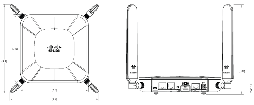
The following figure shows the overall envelope dimensions for the Cisco Catalyst Cellular Gateway unit with antennae attached.
Mounting Feet

The Cisco Catalyst Cellular Gateway has four mounting feet for resting on a desk or shelf. When required, these feet can also secure the Cisco Catalyst Cellular Gateway to the mounting brackets.
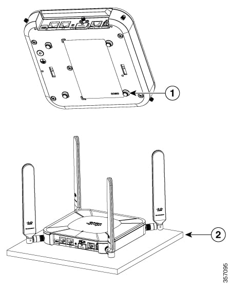
Figure 1. Using Mounting Feet to Rest on a Horizontal Surface or to Secure Cisco Catalyst Cellular Gateway to Mounting Brackets

1

Mounting feet (desktop) or securing screws (for mounting brackets) at four locations

2

Desk or shelf

Mounting Brackets

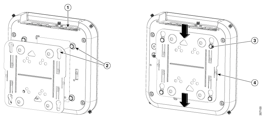
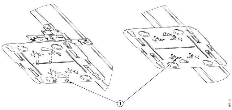
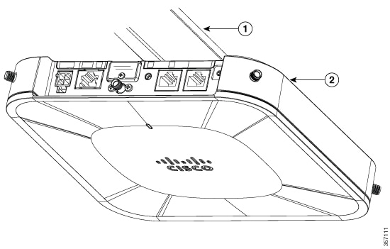
Mounting brackets are required to secure the Cisco Catalyst Cellular Gateway to walls, ceilings, or outlet boxes. The features required for securing the Cisco Catalyst Cellular Gateway to the brackets are integrated with the base assembly.
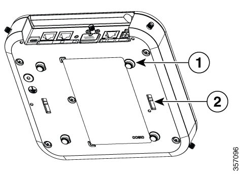
Figure 2. Securing to Mounting Brackets

1

Mounting feet also used for securing the mounting brackets at four locations

2

Slots with detents for securing a mounting bracket (one on each side)

Two mounting bracket options are available; each comes in a kit, which includes a bracket and screws. The screws in the kit are for securing to additional adapter brackets or network electrical boxes (these screws should not be used for securing to walls or hard ceilings). Both the bracket options are suitable for securing to vertical (wall) or overhead surfaces.

Low-Profile Bracket

A low-profile bracket provides a tight fit between the Cisco Catalyst Cellular Gateway unit and the ceiling or wall, but does not accommodate network or electrical boxes or the through-cabling behind the Cisco Catalyst Cellular Gateway unit.
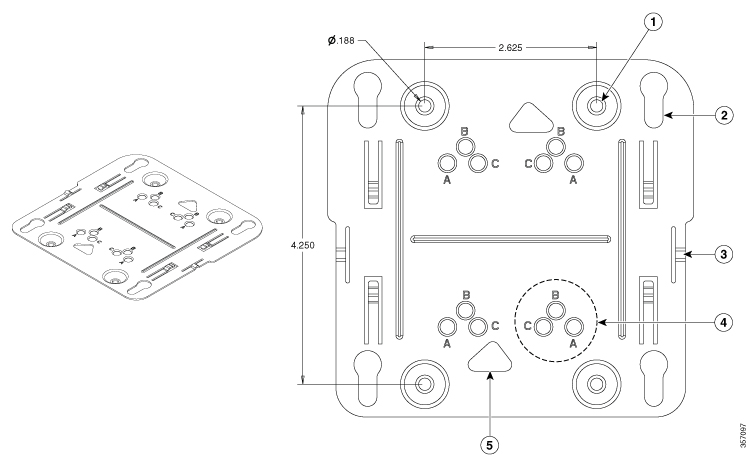
Figure 3. Low-Profile Bracket: Key Features

1

Holes for anchors or screws

2

Key slots (for securing the Cellular Gateway attachment points)

3

Retention or detents to hold the bracket to the Cellular Gateway

4

One set of securing holes for ceiling grid clips (total of four sets)

5

Access cut-out to set screws on ceiling grid clips

Universal Bracket

The Universal bracket is versatile (it works with electrical boxes, can be used for wall mounting, and adapts to ceiling installations), but leaves a larger gap between the Cisco Catalyst Cellular Gateway and the mounting surface than the low-profile bracket. The larger gap is built into the bracket itself and is necessary when cable routing is required behind the Cisco Catalyst Cellular Gateway.
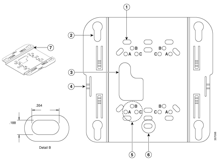
Figure 4. Universal Bracket: Key Features

1

Slots for anchors or screws or network or electrical boxes

2

Key slots (for securing the Cellular Gateway attachment points)

3

Cable routing cut-out

4

Retention detents to hold the bracket to the Cellular Gateway

5

One set of securing holes for ceiling grid clips

6

See detail B (dimensions shown are typical for all slots)

7

Offset between mounting surfaces for cable routing

For many installations, additional clips are required to adapt the securing surface to the mounting brackets. The following table shows mounting bracket reference information and additional clips required for different installation instances.

Table 1. Recommended Brackets and Clips for Installations

CG-BRACKET-1 (Low Profile)

CG-BRACKET-2 (Universal Bracket)

Fit to mounting surface

Small gap

Larger gap

Allows cable routing behind bracket

No

Yes (Top-to-bottom or through bracket cutout to electrical box or hole in wall or ceiling)

Wall or ceiling mount with anchors or screws

Yes (low profile; small gap)

Yes (Larger gap; allows for cabling behind)

Secure to network or electrical boxes

No

Yes

Secures to T-rail suspended ceiling

Yes (With appropriate ceiling grid clips; AIR-AP-T-RAIL-F or -R)

Yes (With appropriate ceiling grid clips; AIR-AP-T-RAIL-F or -R)

Secures to channel rail or beam rail ceiling types

Yes (With appropriate ceiling grid clips; AIR-AP-T-RAIL-F or -R + AIR-CHNL-ADAPTER)

Yes (With appropriate ceiling grid clips; AIR-AP-T-RAIL-F or -R + AIR-CHNL-ADAPTER)

Secure Directly to Hard Surface (Wall or Ceiling)

The Cisco Catalyst Cellular Gateway can be secured directly to walls or hard ceilings with screws or anchors using either of the mounting kits. Note that customers are responsible for selecting the screws or anchors that are appropriate for the surface to which the Cisco Catalyst Cellular Gateway is to be secured.


Note


When securing with anchors or mounting screws, the screws that are provided with each mounting bracket kit shall be discarded. See the figures in the Mounting Bracket section under Mounting Options for the Catalyst Cellular Gateway for bracket hole sizes and spacing for anchor or screw locations.


Follow these steps to mount the Cisco Catalyst Cellular Gateway unit on a solid ceiling or wall:

Procedure


Step 1

Use the mounting bracket as a template to mark the locations of the mounting holes on the bracket. For more information, see Bracket Dimension information.

Caution

 
  • Be sure to mark all the four locations. To ensure a safe and secure installation, make sure you are using adequate fasteners and mount the Cisco Catalyst Cellular Gateway unit using no less than four fasteners.

  • Do not use plastic wall anchors or the keyhole slots on the mounting bracket for ceiling installations. When mounting the cellular gateway unit on a hard ceiling, use four fasteners capable of maintaining a minimum pullout force of 20 lbs (9 kg).

Step 2

Drill appropriate-sized pilot holes at the mounting hole locations you marked for the selected anchors or screws.

Note


The pilot hole size varies according to the material and thickness you are fastening as well as the anchor or screw selected. We recommend that you test the material to determine the ideal hole size for your mounting application.

Step 3

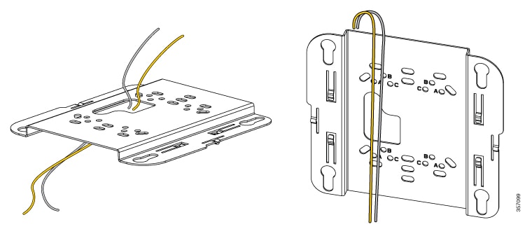
(Optional) If you are routing cables through the cut-out in CG-BRACKET-2, drill or cut a cable access hole near and below the location of the mounting bracket's cable access cutout. Pull approximately 9 inches of cable through the hole. Route the cables through the bracket before you attach the bracket to the ceiling or wall. Route the cables through the main cable access hole and then beyond the end of the bracket for access when the Cellular Gateway is secured to the bracket.

Figure 5. Routing the Cables Through or from Behind CG-BRACKET-2

Step 4

(Optional) Use the ground screw to attach the building ground wire to the Cellular Gateway (reference Grounding section). Connect the cables to the Cisco Catalyst Cellular Gateway unit.

Step 5

Position the mounting bracket mounting holes (with indents down) over the pilot holes.

Step 6

Insert a fastener into each mounting hole and tighten.

Step 7

Connect the cables to the Cellular Gateway unit

Step 8

Align the cellular gateway unit feet with the large part of the keyhole-mounting slots on the mounting plate.

Step 9

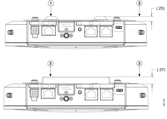
Gently slide the cellular gateway unit onto the mounting bracket keyhole slots until it clicks into place. Either of the brackets can be used for securing to the wall or ceiling, but you should provide different gap offsets. The offset gap (in inches) between Cellular Gateway and the unit is shown in the following figure for the different mounting brackets.

Figure 6. Attach the Cellular Gateway unit to the Secured Mounting Bracket

1

I/O face (facing up)

2

Aligning the Cellular Gateway feet into the top bracket's key slot

3

The Cellular Gateway feet secured through the bottom of the bracket's key slot

4

The bracket detents secured to Cellular Gateway.

Figure 7. Cellular Gateway Orientation when Secured to a Wall: I/O Facing Up

1

I/O face (facing up)

2

LED

3

Cisco logo (oriented as shown)

The offset gap (in inches) between the Cellular Gateway and the unit is shown in the following figure for the different mounting brackets.

Figure 8. Cellular Gateway Spacing when Assembled on Mounting Brackets

1

Low-profile bracket (CG-BRACKET-1)

2

Gap between wall or ceiling and Cellular Gateway base

3

Universal bracket (CG-BRACKET-2)


Mount the Cellular Gateway Unit to a Network or an Electrical Box

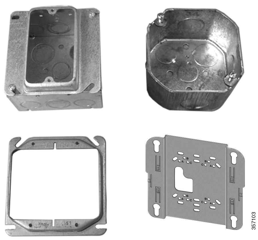
The cellular gateway unit can be mounted to a network or an electrical box using CG-BRACKET-2 because it provides mounting slots that adapt to standard outlet boxes and allows cabling behind the Cellular Gateway and through the bracket.

Figure 9. Network or Electrical Box Using CG-BRACKET-2

Follow these steps to mount the device to a network or an electrical box:

Procedure


Step 1

Position the universal mounting bracket (CG-BRACKET-2) over the existing network or electrical box and align the bracket mounting holes with the box holes.

Step 2

Pull approximately 9 inches of the cables through the cable cutout in the bracket. Route the cables through the bracket before you attach the bracket to the ceiling.

Step 3

Hold the mounting bracket in place and insert the appropriate screws for the box into each of the mounting holes and tighten.

Step 4

(Optional) Use the ground screw to attach the building ground wire to the cellular gateway unit (reference Grounding section).

Step 5

Connect the cables to the cellular gateway unit.

Step 6

Align the cellular gateway unit feet over the keyhole-mounting slots on the mounting bracket.

Step 7

Slide the cellular gateway unit onto the mounting bracket until it clicks into place.

Step 8

Position the universal mounting bracket (CG-BRACKET-2) over the existing network or electrical box and align the bracket mounting holes with the box holes.


Mount Cellular Gateway Unit to a Suspended Ceiling

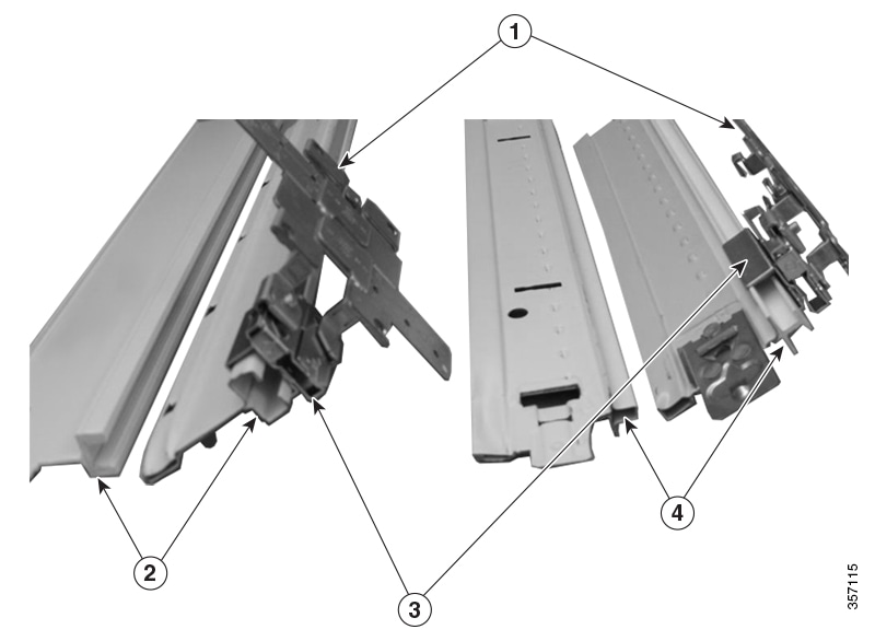
The cellular gateway unit can be mounted to a suspended ceiling (or drop ceiling) with the use of additional clips to secure the mounting bracket. Suspended ceilings consist of a rail and tiles. Three types of suspended ceilings are supported—T-rail, channel rail and beam rail.

Figure 10. Clips to Secure the Mounting Bracket

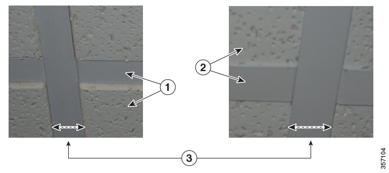
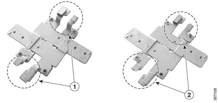
The most common type of ceiling rail is the T-rail. The ceiling grid clips must be placed in order to secure the Cellular Gateway mounting bracket to the T-rail. Two different ceiling grid clip assemblies exist—AIR-AP-T-RAIL-R (for recessed T-rail) and AIR-AP-T-RAIL-F (for T-rails that are flush with ceiling tiles). Each clip assembly adapts to the different standard T-rail widths, but the two kits vary in offset from the T-rail securing point in order to adapt to T-rails that are either flush with the ceiling tile or recessed from the ceiling tile.

Figure 11. Mounting to T-Rail Type Suspended Ceilings

1

T-Rail recessed from ceiling tile

2

T-Rail flush with ceiling tile

3

T-rail can have different widths

Figure 12. Mounting to T-Rail type Suspended Ceilings

1

AIR-AP-T-RAIL-R: Attachment arms are longer to accommodate recessed T-rails

2

AIR-AP-T-RAIL-F: Attachment arms are shorter to provide a narrow gap to T-rails that are flush with ceilings titles.

Follow these steps to mount the cellular gateway unit to a suspended ceiling:

Procedure


Step 1

Decide where you want to mount the cellular gateway unit on your suspended ceiling.

Step 2

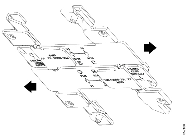
Open the ceiling grid clip completely by sliding the arms apart.

Figure 13. Ceiling Grid Clips Fully Opened [AIR-AP-T-RAIL-F]

Step 3

Place the ceiling grid clip over the T-rail and close it over the appropriate detent (A, B, or C) by sliding the arms together until the attachment arms secure to the T.

Step 4

Use a screw driver to tighten the two-ceiling grid clip-locking screws to prevent the clip from sliding along the T-Rail.

Figure 14. Ceiling Grid Clips Secured to the T-Rail (AIR-AP-T-RAIL-F)

1

T-rail

2

Ceiling grid clip-locking screws

Step 5

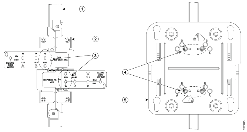
Observe the ceiling grid clip width detent letter (A, B, or C) that corresponds to the T-rail width.

Step 6

Align the corresponding holes (A, B, or C) on the mounting bracket over the mounting holes on the ceiling grid clip.

1

T-rail

2

Ceiling grid clip

3

Securing locations when clip is closed over the T-rail

4

Securing location in mounting bracket aligns with locations indicated by ceiling grid clip

5

Mounting bracket

Step 7

Hold the mounting bracket and insert a 6-32 x 1/4 in. screw into each of the three corresponding holes (A, B, or C) and tighten.

Note


One extra mounting screw is provided in each kit (5 screws in total) in case one is lost.

Figure 15. Secure Mounting Bracket to the Ceiling Grid Clips - (CG-BRACKET-1)

1

Secure screws provided with the mounting bracket kit

Step 8

(Optional) If necessary, drill or cut a cable access hole in the ceiling tile, which is large enough for the Ethernet and power cables. If cable routing is required through the ceiling, CG-BRACKET-2 must be used. Pull the cables through the access hole until you have about 1 foot of cable protruding from the hole.

Reference figure 5. for cable routing through (CG-BRACKET-2)

Step 9

(Optional) Use the ground screw to ground the cellular gateway unit to a suitable building ground (reference Grounding section).

Step 10

Connect the cables to the cellular gateway unit.

Step 11

Align the cellular gateway unit feet over the keyhole-mounting slots on the mounting bracket. If you created a hole for the cables, make sure the cellular gateway unit is positioned such that the cables reach their respective ports.

Step 12

Gently slide the cellular gateway unit onto the mounting bracket until it clicks into place.

Figure 16. Cellular Gateway Secured to T-Rail Ceiling

1

T-Rail (Tile not shown)

2

Cellular gateway (Antennae not shown)


Gap when Installing Mounting Brackets to T-Rails

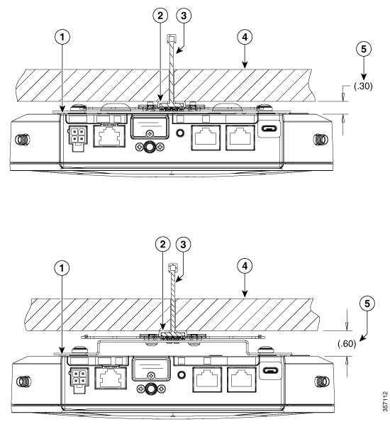
The low-profile bracket is recommended for use with flush-drop ceilings, but the universal mounting bracket can be used, if required.

Figure 17. T-Rail Flush with the Ceiling Tile

Sl no

Description

1

CG-Bracket-1 (Low-profile) (Figure on top)

CG-Bracket-2 (Universal) (Figure at the bottom)

2

Flush ceiling grid clips (AIR-AP-T-RAIL-F)

3

T-Rail

4

Ceiling tile

5

GAP: Tile to cellular gateway base

The selection of mounting bracket for use with the T-rails recessed from the ceiling tile depends on usage and tile-recess depth.

Figure 18. T-Rail with Recessed Ceiling Tile

1

Maximum tile recess for use with bracket (in inches)

2

CG-Bracket-1 (Low-profile) (Figure on top)

CG-Bracket-2 (Universal) (Figure at the bottom)

3

Recessed ceiling grid clips (AIR-AP-T-RAIL-R)

4

T-Rail

5

Ceiling tile

6

GAP: Tile recess to cellular gateway base

Mount to Channel-Rail and Beam-Rail Ceilings

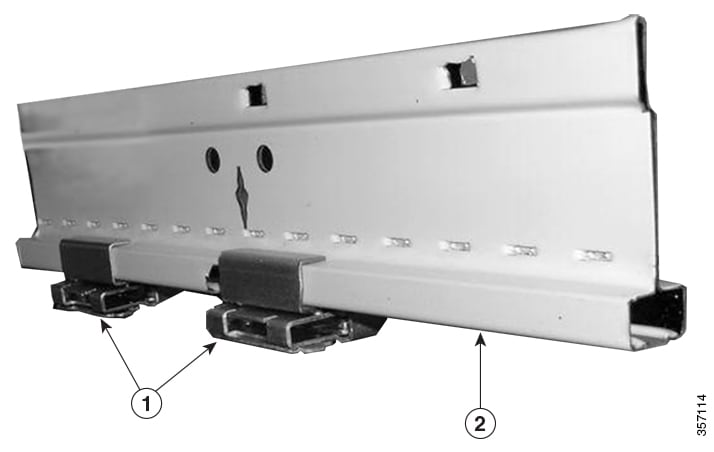
Channel rails and Beam rails require the use of special ceiling adapter clips (AIR-CHNL-ADAPTER) as an adapter for the ceiling-grid support clips (AIR-AP-T-RAIL-R or –F). Qty (two) AIR-CHNL-ADAPTER clips are required for each cellular gateway unit.

Figure 19. Channel Rail

1

Adapter clips secured. Ceiling grid clips secured to adapter clip edges

2

Channel rail

Figure 20. Assembling the Air Channel Adapter

1

Ceiling grid clips

2

Channel rail

3

Adapter clips (air channel adapter)

4

Beam rail

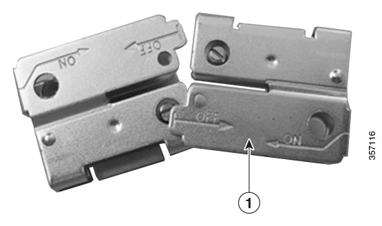
Each adapter clip is a 2-piece assembly with set screws. Assemble the air channel adapter clip as follows:

Procedure


Step 1

Orient the clips such that the text of both items is on the same side, as in the following figure. Orient the items such that the ON arrows point to each other (the OFF arrows point away from each other).

Figure 21. Adapter Clips Lined Up

1

Off and ON arrows

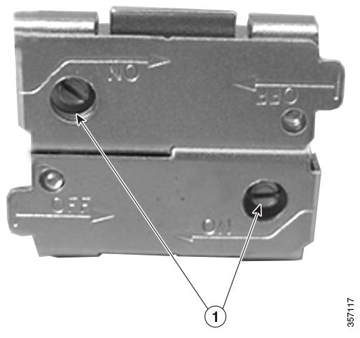
Step 2

Push the two clips together in the ON direction.

Step 3

Tighten the set screws securely to the rail.

Figure 22. Adapter Clips Pushed Together

1

Set screws (keep clip secure on rail)