Cisco XR 12410 and Cisco XR 12810 Router Chassis Installation Guide
Bias-Free Language
The documentation set for this product strives to use bias-free language. For the purposes of this documentation set, bias-free is defined as language that does not imply discrimination based on age, disability, gender, racial identity, ethnic identity, sexual orientation, socioeconomic status, and intersectionality. Exceptions may be present in the documentation due to language that is hardcoded in the user interfaces of the product software, language used based on RFP documentation, or language that is used by a referenced third-party product. Learn more about how Cisco is using Inclusive Language.
- Updated:
- July 9, 2008
Chapter: Chapter 3 - Installing the Router
- Pre-Installation Considerations and Requirements
- Installation Overview
- Removing Components Before Installing the Chassis
- Removing Cards from the Chassis
- Rack-Mounting the Router Chassis
- Supplemental Bonding and Grounding Connections
- Reinstalling Components After Installing the Chassis
- Reinstalling Cards in the Chassis
- Connecting Line Card Network Interface Cables
- Connecting PRP Route Processor Cables
- Connecting Alarm Display Card Cables
- Connecting Power to the Router
Installing the Cisco XR 12410 Router
This chapter contains the procedures to install the router in a rack. The installation is presented in the following sections:
•![]() Pre-Installation Considerations and Requirements
Pre-Installation Considerations and Requirements
•![]() Removing Components Before Installing the Chassis
Removing Components Before Installing the Chassis
•![]() Removing Cards from the Chassis
Removing Cards from the Chassis
•![]() Rack-Mounting the Router Chassis
Rack-Mounting the Router Chassis
•![]() Supplemental Bonding and Grounding Connections
Supplemental Bonding and Grounding Connections
•![]() Reinstalling Components After Installing the Chassis
Reinstalling Components After Installing the Chassis
•![]() Reinstalling Cards in the Chassis
Reinstalling Cards in the Chassis
•![]() Connecting Line Card Network Interface Cables
Connecting Line Card Network Interface Cables
•![]() Connecting PRP Route Processor Cables
Connecting PRP Route Processor Cables
•![]() Connecting Alarm Display Card Cables
Connecting Alarm Display Card Cables
•![]() Connecting Power to the Router
Connecting Power to the Router
Pre-Installation Considerations and Requirements
Before you perform any procedures in this chapter, review the following sections in Chapter 2, "Preparing for Installation."
•![]() Site Requirement Guidelines, page 2-6
Site Requirement Guidelines, page 2-6
In particular, observe the guidelines for preventing electrostatic discharge (ESD) damage described in the "Compliance and Safety Information" section on page 2-3 and use Figure 2-1 on page 2-4 as a reference in locating and using the ESD sockets on the front of the router chassis.
For additional safety and compliance information, refer to the Regulatory Compliance and Safety Information for Cisco 12000 Series Routers publication that accompanied your router.

Warning ![]() This router is not designed to be installed as a shelf-mounted or a free-standing router. The router must be installed in a rack that is secured to the building structure. You must install the router in either a telco-style frame or a four-post equipment rack.
This router is not designed to be installed as a shelf-mounted or a free-standing router. The router must be installed in a rack that is secured to the building structure. You must install the router in either a telco-style frame or a four-post equipment rack.
Installation Overview
The router is shipped strapped to a shipping pallet as shown in Figure 3-1.
Figure 3-1 Router Packaged on Shipping Pallet
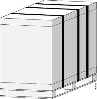
A fully equipped router with two power supplies can weigh as much as 275 pounds (124.74 kg); an empty chassis weighs 125 pounds (56.7 kg). The chassis is designed to be lifted by two persons after you remove some of the components, such as line cards, power supplies, and the blower module, to reduce the weight before lifting the chassis. See the "Removing Components Before Installing the Chassis" section for procedures to remove these components.
Required Tools and Equipment
Before you begin the rack-mount installation, you must read and understand the information in the "Rack-Mounting Guidelines" section on page 2-6 and have the following tools and equipment:
•![]() ESD-preventive wrist strap
ESD-preventive wrist strap
•![]() Number 1 and number 2 Phillips screwdrivers
Number 1 and number 2 Phillips screwdrivers
•![]() 1/4-inch (6.35-mm) and 3/16-inch (4.5-mm) flat-blade screwdrivers
1/4-inch (6.35-mm) and 3/16-inch (4.5-mm) flat-blade screwdrivers
•![]() Tape measure
Tape measure
•![]() Level (optional)
Level (optional)
•![]() A minimum of 10 slotted binderhead screws (usually provided with the rack) to secure the chassis to the mounting flanges (also called rails) in the rack. Five screws should be installed on each side of the chassis.
A minimum of 10 slotted binderhead screws (usually provided with the rack) to secure the chassis to the mounting flanges (also called rails) in the rack. Five screws should be installed on each side of the chassis.
•![]() 3/8-inch (10-mm) nutdriver (for systems equipped with the DC-input power shelf)
3/8-inch (10-mm) nutdriver (for systems equipped with the DC-input power shelf)
•![]() 9/16-inch (14-mm) wrench (for chassis hold-down bolts and pallet hold-down bracket bolts)
9/16-inch (14-mm) wrench (for chassis hold-down bolts and pallet hold-down bracket bolts)
•![]() 3/4-inch (19-mm) socket and ratchet wrench
3/4-inch (19-mm) socket and ratchet wrench
Unpacking and Positioning the Router
Follow the unpacking instructions shipped with the router and use a safety hand truck to move the router to the location where it is being installed in a rack.
Save the packaging materials in case the router needs repackaging or shipping.
Removing Components Before Installing the Chassis
The router is designed to be lifted by two persons into a rack. To reduce the weight of the system, you can remove some of the components before attempting to lift it into the rack.
Use the following procedure to remove the front cover from the router.
Step 1 ![]() Open the front door by pressing the right latch button (Figure 3-2).
Open the front door by pressing the right latch button (Figure 3-2).
Figure 3-2 Opening the Front Door

|
|
Front Door Latch |
Step 2 ![]() Remove the front door by lifting the (top and bottom) hinge pins to free the door from the chassis (Figure 3-3).
Remove the front door by lifting the (top and bottom) hinge pins to free the door from the chassis (Figure 3-3).

Step 3 ![]() Reinstall the hinge pins into the chassis hinge brackets.
Reinstall the hinge pins into the chassis hinge brackets.
Figure 3-3 Removing or Installing Hinge Pins

Removing Power Supplies
Remove both power supplies to reduce the top-end weight of the router by approximately 28 pounds (12.70 kg) to 40 pounds (18.14 kg).
Removing AC PEMs
Use the following procedure to remove the AC PEMs from the chassis.
Step 1 ![]() Remove the PEM from the chassis (Figure 3-4):
Remove the PEM from the chassis (Figure 3-4):
a. ![]() Loosen the captive screw on the ejector lever.
Loosen the captive screw on the ejector lever.
b. ![]() Pivot the lever down to eject the PEM from its bay.
Pivot the lever down to eject the PEM from its bay.
c. ![]() Slide the power supply out of its bay while supporting it with your other hand.
Slide the power supply out of its bay while supporting it with your other hand.
Warning ![]() The power supply weighs approximately 20 pounds (9 kg). Use two hands to remove the power supply.
The power supply weighs approximately 20 pounds (9 kg). Use two hands to remove the power supply.
Figure 3-4 Removing an AC Power Supply

Step 2 ![]() Repeat Step 1 for the other PEM.
Repeat Step 1 for the other PEM.
Removing DC PEMs
Use the following procedure to remove the DC PEMs from the chassis.
Step 1 ![]() Remove the PEM from the chassis (Figure 3-5):
Remove the PEM from the chassis (Figure 3-5):
a. ![]() Loosen the captive screw on the ejector lever.
Loosen the captive screw on the ejector lever.
b. ![]() Pivot the lever down to eject the PEM from its bay.
Pivot the lever down to eject the PEM from its bay.
c. ![]() Slide the PEM out of its bay while supporting it with your other hand.
Slide the PEM out of its bay while supporting it with your other hand.
Warning ![]() The DC PEM weighs approximately 14 pounds (6.35 kg). Use two hands to remove the power supply.
The DC PEM weighs approximately 14 pounds (6.35 kg). Use two hands to remove the power supply.
Figure 3-5 Removing a DC PEM

Step 2 ![]() Repeat Step 1 for the other PEM.
Repeat Step 1 for the other PEM.
Removing the Blower Module
By removing the blower module from the chassis, you can reduce the top-end weight of the chassis by approximately 20.5 pounds (9.3 kg).
Use the following procedure to remove the blower module from the chassis (Figure 3-6).
Step 1 ![]() Loosen the captive screw on each side of the blower module.
Loosen the captive screw on each side of the blower module.
Step 2 ![]() Pull the blower module halfway out of the module bay.
Pull the blower module halfway out of the module bay.
Step 3 ![]() Slide out the blower module completely from the module bay while supporting it with your other hand.
Slide out the blower module completely from the module bay while supporting it with your other hand.
Warning ![]() The blower module weighs approximately 20 pounds (9 kg). Use two hands when handling the blower module.
The blower module weighs approximately 20 pounds (9 kg). Use two hands when handling the blower module.
Figure 3-6 Removing the Blower Module

Removing Cards from the Chassis
To reduce additional weight from the chassis, you can remove all line cards, RPs, switch fabrics, and alarm cards. This section describes how to remove the various types of cards.
Removing Cards from the Line Card and RP Card Cage
The line card and RP card cage contains 10 slots (numbered 0 through 9, from left to right). Line cards are installed in slots 0 through 7; RPs are installed in slots 8 and 9.
Use the following procedure to remove line cards and RPs from of the chassis.
Step 1 ![]() Proceeding from left to right, identify each card and write down the card type and slot number on a piece of paper (Figure 3-7).
Proceeding from left to right, identify each card and write down the card type and slot number on a piece of paper (Figure 3-7).

Note ![]() You will need this information when you reinstall the cards in the chassis to be sure you install them in the same card slots.
You will need this information when you reinstall the cards in the chassis to be sure you install them in the same card slots.
Figure 3-7 Cisco XR 12410 router Components and Slot-Numbering

Step 2 ![]() Starting at slot 0:
Starting at slot 0:
a. ![]() Loosen the captive screws at the top and bottom of the front panel (Figure 3-8a).
Loosen the captive screws at the top and bottom of the front panel (Figure 3-8a).
b. ![]() Pivot the ejector levers to unseat the card from the backplane connector (Figure 3-8b.)
Pivot the ejector levers to unseat the card from the backplane connector (Figure 3-8b.)
c. ![]() Slide the card out of the slot (Figure 3-8c) and place it directly into an antistatic bag or other ESD-preventive container.
Slide the card out of the slot (Figure 3-8c) and place it directly into an antistatic bag or other ESD-preventive container.
Figure 3-8 Removing a Line Card from the Line Card and RP Card Cage

Step 3 ![]() Repeat Step 2 for each line card.
Repeat Step 2 for each line card.
Removing Cards from the Switch Fabric and Alarm Card Cage
The switch fabric and alarm card cage is located behind the air filter door on the front of the chassis. The card cage has seven keyed, vertical card slots for the clock scheduler cards and switch fabric cards.
As shown in Figure 3-7, CSCs are installed in the left two card slots; SFCs are installed in the center five slots. Two alarm cards are installed in the right two card slots of the switch fabric and alarm card cage.
Use the following procedure to remove cards from the switch fabric and alarm card cage.
Step 1 ![]() Loosen the captive screws on each side of the air filter door and swing the door away from the switch fabric and alarm card cage (Figure 3-9).
Loosen the captive screws on each side of the air filter door and swing the door away from the switch fabric and alarm card cage (Figure 3-9).
Figure 3-9 Opening the Air Filter Door

Step 2 ![]() Starting at slot CSC0:
Starting at slot CSC0:
a. ![]() Pivot the ejector levers to unseat the card from the backplane connector (Figure 3-10).
Pivot the ejector levers to unseat the card from the backplane connector (Figure 3-10).
b. ![]() Slide the card out of the slot and place it directly into an antistatic bag or other ESD-preventive container.
Slide the card out of the slot and place it directly into an antistatic bag or other ESD-preventive container.
Figure 3-10 Removing a Card from the Switch Fabric and Alarm Card Cage

Step 3 ![]() Repeat Step 2 for each card.
Repeat Step 2 for each card.
Step 4 ![]() Close the air filter door and tighten the captive screws to prevent the door from opening during the chassis installation.
Close the air filter door and tighten the captive screws to prevent the door from opening during the chassis installation.
Rack-Mounting the Router Chassis
The router chassis can be installed in either a front-mounted position or a center-mounted position as shown in Figure 3-11.
Figure 3-11 Front-Mount and Center-Mount Rack Positions
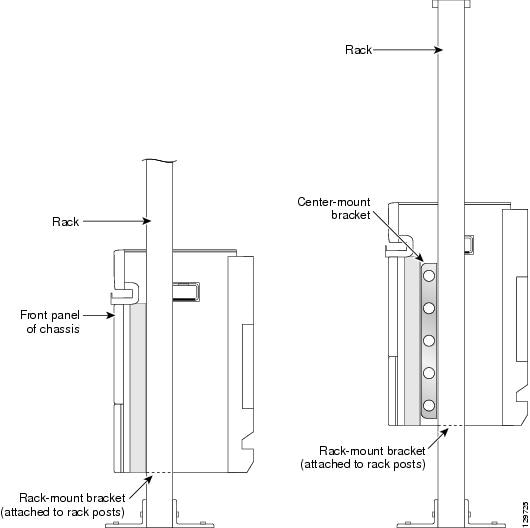
In a front-mounted position, the chassis rack-mounting flanges are secured directly to the rack posts.
In a center-mounted position, an optional set of center-mount brackets are secured to the rack posts and the chassis rack-mounting flanges are then secured to the center-mount brackets. The center-mounted position moves the center of gravity of the chassis closer to the vertical axis of the rack posts, which adds to the security and stability of the rack installation.
Verifying Rack Dimensions
Before you install the chassis, measure the space between the vertical mounting flanges (rails) on your equipment rack to verify that the rack conforms to the measurements shown in Figure 3-12.
Step 1 ![]() Mark and measure the distance between two holes on the left and right mounting rails.
Mark and measure the distance between two holes on the left and right mounting rails.
The distance should measure 18.31 inches ± 0.06 inches (46.5 cm ± 0.15 cm).
Note ![]() Measure for pairs of holes near the bottom, middle and top of the equipment rack to ensure that the rack posts are parallel.
Measure for pairs of holes near the bottom, middle and top of the equipment rack to ensure that the rack posts are parallel.
Step 2 ![]() Measure the space between the inner edges of the left front and right front mounting flanges on the equipment rack.
Measure the space between the inner edges of the left front and right front mounting flanges on the equipment rack.
The space must be at least 17.7 inches (45 cm) to accommodate the chassis which is 17.25 inches (43.8 cm) wide and fits between the mounting posts on the rack.
Figure 3-12 Verifying Equipment Rack Dimensions

Installing Rack-Mount Brackets—Optional
The router accessory kit ships with a pair of rack-mount brackets that can be used as a temporary aid to bear the weight of the chassis while it is being positioned and secured in the equipment rack. Using these mounting brackets is optional, but highly recommended to make installation easier. The rack-mount brackets can be left in place after the chassis is installed.
Note ![]() Before installing the rack-mount brackets, make sure you have performed the measurements described in "Verifying Rack Dimensions" section.
Before installing the rack-mount brackets, make sure you have performed the measurements described in "Verifying Rack Dimensions" section.
Use the following procedure to install the rack-mount brackets.
Step 1 ![]() Determine the location in which you want to position the chassis in the rack, and mark holes at the same height on both the left and right rack rails.
Determine the location in which you want to position the chassis in the rack, and mark holes at the same height on both the left and right rack rails.
Step 2 ![]() Install the right rack-mount bracket (Figure 3-13).
Install the right rack-mount bracket (Figure 3-13).
a. ![]() Align the bottom screw hole of the bracket with the marked screw hole at the bottom of the rack and finger tighten a screw in that hole.
Align the bottom screw hole of the bracket with the marked screw hole at the bottom of the rack and finger tighten a screw in that hole.
b. ![]() Finger-tighten a second screw in the top hole of the bracket.
Finger-tighten a second screw in the top hole of the bracket.
c. ![]() Use a screwdriver to tighten both screws securely.
Use a screwdriver to tighten both screws securely.
Step 3 ![]() Repeat Step 2 for the left rack-mount bracket.
Repeat Step 2 for the left rack-mount bracket.
Step 4 ![]() Use a level to verify that the tops of the two brackets are level, or use a measuring tape to verify that both brackets are the same distance from the top of the rack rails.
Use a level to verify that the tops of the two brackets are level, or use a measuring tape to verify that both brackets are the same distance from the top of the rack rails.
Figure 3-13 Installing the Left and Right Rack-Mount Brackets

Installing Center-Mount Brackets—Optional
If you plan to install the router in the center-mount position, you must install the center-mount brackets to the rack rails first. If you do not plan to use the optional center-mount brackets, proceed directly to the "Installing the Chassis in the Rack" section.
The optional center-mount bracket installation kit ships in the accessories box included with the router and contains the following:
•![]() Two center-mount brackets.
Two center-mount brackets.
•![]() 10 (minimum) Phillips binderhead screws (usually provided with the bracket kit) to secure the brackets to the mounting flanges (also called rails) in the rack. Five screws should be installed on each bracket.
10 (minimum) Phillips binderhead screws (usually provided with the bracket kit) to secure the brackets to the mounting flanges (also called rails) in the rack. Five screws should be installed on each bracket.
Contact a Cisco service representative for assistance if any parts are missing.
Note ![]() Before installing the center-mount brackets, make sure you have performed the measurements described in "Verifying Rack Dimensions" section.
Before installing the center-mount brackets, make sure you have performed the measurements described in "Verifying Rack Dimensions" section.
Use the following procedure to install the center-mount brackets to the rack rails.
Step 1 ![]() Determine the location in which you want to position the bottom of the router chassis in the rack, and mark holes at the same height on both the left and right rack rails.
Determine the location in which you want to position the bottom of the router chassis in the rack, and mark holes at the same height on both the left and right rack rails.
Step 2 ![]() Identify the orientation of the left and right center-mount brackets (Figure 3-14).
Identify the orientation of the left and right center-mount brackets (Figure 3-14).
Figure 3-14 Center-Mount Brackets

Step 3 ![]() Install the right center-mount bracket (Figure 3-15).
Install the right center-mount bracket (Figure 3-15).
a. ![]() Align the bottom screw hole of the bracket with the marked screw hole at the bottom of the rack and finger tighten a screw in that hole.
Align the bottom screw hole of the bracket with the marked screw hole at the bottom of the rack and finger tighten a screw in that hole.
b. ![]() Finger-tighten a second screw in the top hole of the bracket.
Finger-tighten a second screw in the top hole of the bracket.
c. ![]() Finger- tighten three more screws in the middle of in the bracket.
Finger- tighten three more screws in the middle of in the bracket.
d. ![]() Use a screwdriver to tighten all five screws securely.
Use a screwdriver to tighten all five screws securely.
Step 4 ![]() Repeat Step 3 for the left center-mount bracket.
Repeat Step 3 for the left center-mount bracket.
Step 5 ![]() Use a level to verify that the tops of the two brackets are level, or use a measuring tape to verify that both brackets are the same distance from the top of the rack rails.
Use a level to verify that the tops of the two brackets are level, or use a measuring tape to verify that both brackets are the same distance from the top of the rack rails.
Figure 3-15 Installing a Center-Mount Rack-Mounting Bracket

Installing the Chassis in the Rack
Two people can lift an empty router chassis using the handles on the sides. To accommodate racks with different hole patterns in their mounting flanges, the chassis rack-mounting flanges have three groups of eight oblong screw holes on each side.
This section describes how to install the chassis in a telco rack.
Figure 3-16 shows the orientation of the chassis to the rack posts.
Figure 3-16 Router and Rack Posts

Use the following procedure to install the chassis in the equipment rack:
Step 1 ![]() Using two people, lift the chassis into the rack using the side handles and grasping underneath the power supply bays (Figure 3-17).
Using two people, lift the chassis into the rack using the side handles and grasping underneath the power supply bays (Figure 3-17).
Warning ![]() An empty chassis weighs approximately 125 pounds (56.7 kg). You need two people to slide the chassis into the equipment rack safely.
An empty chassis weighs approximately 125 pounds (56.7 kg). You need two people to slide the chassis into the equipment rack safely.
•![]() If you are using the rack-mount brackets, raise the chassis to the level of the brackets. Let the bottom of the chassis rest on the brackets, but continue to support the chassis.
If you are using the rack-mount brackets, raise the chassis to the level of the brackets. Let the bottom of the chassis rest on the brackets, but continue to support the chassis.
Figure 3-17 Correct Lifting Positions

Figure 3-18 Incorrect Lifting Handholds

Step 2 ![]() Position the chassis until the rack-mounting flanges are flush against the mounting rails on the rack (or the optional center-mount brackets, if installed).
Position the chassis until the rack-mounting flanges are flush against the mounting rails on the rack (or the optional center-mount brackets, if installed).
Step 3 ![]() Hold the chassis in position against the mounting rails while the second person finger-tightens a screw to the rack rails on each side of the chassis.
Hold the chassis in position against the mounting rails while the second person finger-tightens a screw to the rack rails on each side of the chassis.
Step 4 ![]() Finger-tighten 4 more screws to the rack rails on each side of the chassis.
Finger-tighten 4 more screws to the rack rails on each side of the chassis.
•![]() Space the screws evenly between the top and bottom of the chassis.
Space the screws evenly between the top and bottom of the chassis.
Step 5 ![]() Tighten all 5 screws on each side to secure the chassis to the equipment rack.
Tighten all 5 screws on each side to secure the chassis to the equipment rack.
Supplemental Bonding and Grounding Connections
Before you connect power to the router, or power on the router for the first time, We recommend that you connect the central office ground system or new equipment building system (NEBS) to the supplemental bonding and grounding points on the router. For more information on supplemental bonding and grounding cable requirements, see the "NEBS Supplemental Unit Bonding and Grounding Guidelines" section on page 2-18.
Use the following procedure to attach a grounding cable lug to the router:
Step 1 ![]() Install the locking washers and nuts over the bonding and grounding cable studs and tighten securely (Figure 3-19).
Install the locking washers and nuts over the bonding and grounding cable studs and tighten securely (Figure 3-19).
Figure 3-19 Router Rear NEBS Bonding and Grounding Studs

Step 2 ![]() Prepare the other end of the grounding wire and connect it to the appropriate grounding point at your site to ensure an adequate earth ground.
Prepare the other end of the grounding wire and connect it to the appropriate grounding point at your site to ensure an adequate earth ground.
Reinstalling Components After Installing the Chassis
This section describes how to reinstall the components that you removed before installing the chassis in the rack. It also describes how to reconnect cables to line cards, the RP, and alarm cards.
Reinstalling Power Supplies
Use the following procedures to reinstall the AC or DC power supplies.
•![]() To reinstall AC PEMs, go to Reinstalling AC PEMs
To reinstall AC PEMs, go to Reinstalling AC PEMs
•![]() To reinstall DC PEMs, go to Reinstalling DC PEMs
To reinstall DC PEMs, go to Reinstalling DC PEMs
Reinstalling AC PEMs
Use the following procedure to reinstall the AC PEMs back into the chassis.
Step 1 ![]() Install the AC PEMs (Figure 3-20):
Install the AC PEMs (Figure 3-20):
a. ![]() Slide the power supply into the bay until it mates with its backplane connector.
Slide the power supply into the bay until it mates with its backplane connector.
b. ![]() Lift the ejector lever into place and tighten the captive screw to securely seat the power supply to the backplane connector.
Lift the ejector lever into place and tighten the captive screw to securely seat the power supply to the backplane connector.
Figure 3-20 Installing an AC PEM

Step 2 ![]() Repeat Step 1 for the other power supply.
Repeat Step 1 for the other power supply.
Step 3 ![]() Go to the "Reinstalling the Blower Module" section to install the blower module.
Go to the "Reinstalling the Blower Module" section to install the blower module.
Reinstalling DC PEMs
Use the following procedure to reinstall the DC PEMs back into the chassis.
Step 1 ![]() Install the DC PEM (Figure 3-21):
Install the DC PEM (Figure 3-21):
a. ![]() Slowly push the power supply into the chassis until it mates with the backplane connector at the back of the bay.
Slowly push the power supply into the chassis until it mates with the backplane connector at the back of the bay.
b. ![]() Lift the ejector lever into place and tighten the captive screw to securely seat the power supply to the backplane connector.
Lift the ejector lever into place and tighten the captive screw to securely seat the power supply to the backplane connector.
Figure 3-21 Installing a DC PEM

Step 2 ![]() Repeat Step 1 for the other power supply.
Repeat Step 1 for the other power supply.
Step 3 ![]() Go to the "Reinstalling the Blower Module" section to install the blower module.
Go to the "Reinstalling the Blower Module" section to install the blower module.
Reinstalling the Blower Module
Use the following procedure to reinstall the blower module in the chassis.
Step 1 ![]() Install the blower module into the chassis (Figure 3-22):
Install the blower module into the chassis (Figure 3-22):
a. ![]() Lift the blower module (with two hands) and slide it halfway into the module bay.
Lift the blower module (with two hands) and slide it halfway into the module bay.
b. ![]() Slowly push the blower module into the chassis until it mates with the backplane connector at the back of the module bay.
Slowly push the blower module into the chassis until it mates with the backplane connector at the back of the module bay.
c. ![]() Tighten the captive screws on the blower module to secure it to the chassis.
Tighten the captive screws on the blower module to secure it to the chassis.
Figure 3-22 Installing the Blower Module

Step 2 ![]() Go to the "Reinstalling Cards in the Switch Fabric and Alarm Card Cage" section to reinstall SFCS cards.
Go to the "Reinstalling Cards in the Switch Fabric and Alarm Card Cage" section to reinstall SFCS cards.
Reinstalling Cards in the Chassis
This section describes how to reinstall various line cards back into the chassis.
Reinstalling Cards in the Switch Fabric and Alarm Card Cage
Use the following procedure to reinstall cards into the switch fabric and alarm card cage (refer to Figure 3-7 for slot numbering).
Step 1 ![]() Loosen the two captive screws on each side of the air filter door and swing the door away from the switch fabric and alarm card cage (Figure 3-7).
Loosen the two captive screws on each side of the air filter door and swing the door away from the switch fabric and alarm card cage (Figure 3-7).
Figure 3-23 Opening the Air Filter Door
Step 2 ![]() Starting at slot CSC0:
Starting at slot CSC0:
d. ![]() Slide the card into the slot (Figure 3-24).
Slide the card into the slot (Figure 3-24).
a. ![]() Pivot the ejector levers to seat the card to the backplane connector.
Pivot the ejector levers to seat the card to the backplane connector.
Figure 3-24 Reinstalling a Clock Scheduler Card into the Switch Fabric and Alarm Card Cage
Step 3 ![]() Repeat Step 2 for each card.
Repeat Step 2 for each card.
Step 4 ![]() Close the air filter door and tighten the captive screws to prevent the door from opening during chassis installation.
Close the air filter door and tighten the captive screws to prevent the door from opening during chassis installation.
Step 5 ![]() Go to the "Reinstalling Cards in the Line Card and RP Card Cage" section to reinstall the line cards and RP.
Go to the "Reinstalling Cards in the Line Card and RP Card Cage" section to reinstall the line cards and RP.
Reinstalling Cards in the Line Card and RP Card Cage
Before you begin reinstalling cards in the card cage, identify slot assignments by referring to the written list you prepared when you removed the cards (refer to Figure 3-7 for slot-numbering).
Use the following procedure to reinstall cards in the line card and RP card cage.
Step 1 ![]() Starting at slot 0 (Figure 3-25):
Starting at slot 0 (Figure 3-25):
b. ![]() Slide the card into the slot until it mates with the backplane connector.
Slide the card into the slot until it mates with the backplane connector.
a. ![]() Tighten the captive screws at the top and bottom of the front panel.
Tighten the captive screws at the top and bottom of the front panel.
Figure 3-25 Installing a Line Card into the Line Card and RP Card Cage

Step 2 ![]() Repeat Step 2 for each line card.
Repeat Step 2 for each line card.
Step 3 ![]() Go to the "Connecting Line Card Network Interface Cables" section to connect the network interface cables.
Go to the "Connecting Line Card Network Interface Cables" section to connect the network interface cables.
Connecting Line Card Network Interface Cables
This section describes how to route the network interface cables through the
router cable-management system and attach the network interface cables to the line card ports.
This procedure uses an 8-port fiber-optic Fast Ethernet card as an example to describe how to attach a network interface cable to a line card port and route the cable through the cable-management system. Depending on which line cards are installed in your system, your cable connection procedure might differ slightly from this example. For cable connection information for your specific line card, refer to the installation and configuration note for that line card.
Note ![]() You can access the most current Cisco line card documentation on the World Wide Web at: http://www.cisco.com.
You can access the most current Cisco line card documentation on the World Wide Web at: http://www.cisco.com.
Use the following procedure as an example to route the network interface cables through the cable-management system and connect them to the line card.
Step 1 ![]() Route an interface cable across the horizontal cable-management tray, through the cable tray opening to connect it to the line card:
Route an interface cable across the horizontal cable-management tray, through the cable tray opening to connect it to the line card:
•![]() For legacy fiber-optic line cards, go to Step 2.
For legacy fiber-optic line cards, go to Step 2.
•![]() For current fiber-optic line cards, go to Step 6.
For current fiber-optic line cards, go to Step 6.
Step 2 ![]() Install a plastic bend-radius clip on the strain-relief ferrule on the connector (see blow-out in Figure 3-26).
Install a plastic bend-radius clip on the strain-relief ferrule on the connector (see blow-out in Figure 3-26).
Note ![]() The bag of bend-radius clips (Part Number 800-06119-01) in the accessories box that shipped with your router contains two sizes of bend-radius clips. The clip size is determined by the diameter of the strain-relief ferrule on the cable connectors. Use the size that provides the most secure fit on the strain-relief ferrule on the cable connectors in use at your site.
The bag of bend-radius clips (Part Number 800-06119-01) in the accessories box that shipped with your router contains two sizes of bend-radius clips. The clip size is determined by the diameter of the strain-relief ferrule on the cable connectors. Use the size that provides the most secure fit on the strain-relief ferrule on the cable connectors in use at your site.
Step 3 ![]() Insert the cable connector into its assigned port.
Insert the cable connector into its assigned port.
Step 4 ![]() Route the cable up the cable-management bracket and carefully press the cable into the channel so it is held in place by the cable clips (Figure 3-26b).
Route the cable up the cable-management bracket and carefully press the cable into the channel so it is held in place by the cable clips (Figure 3-26b).
Step 5 ![]() Repeat Steps 3 through 5 for each additional cable connection to that line card.
Repeat Steps 3 through 5 for each additional cable connection to that line card.
Figure 3-26 Connecting a Network Interface Cable to a Legacy Line Card

Step 6 ![]() Insert all cables into their assigned ports.
Insert all cables into their assigned ports.
Step 7 ![]() Place several evenly spaced velcro straps through slots on the cable-management bracket (Figure 3-27a).
Place several evenly spaced velcro straps through slots on the cable-management bracket (Figure 3-27a).
Step 8 ![]() Route the cables alongside the cable-management bracket and secure them with the velcro straps as appropriate (Figure 3-27b).
Route the cables alongside the cable-management bracket and secure them with the velcro straps as appropriate (Figure 3-27b).
Figure 3-27 Current Style Cable Management Bracket

Connecting PRP Route Processor Cables
This section describes how to connect cables to the console, auxiliary, and Ethernet ports on the PRP. The console and auxiliary ports are both asynchronous serial ports; any devices connected to these ports must be capable of asynchronous transmission. For example, most modems are asynchronous devices.
Figure 3-28 shows an example of a data terminal and modem connections.
Figure 3-28 PRP Console and Auxiliary Port Connections

|
|
Modem |
|
Auxiliary port |
|
|
Console terminal |
|
Console port |
|
|
RJ-45 Ethernet cables |
— |
Note ![]() RP cables are not available from Cisco, but are available from any commercial cable vendor.
RP cables are not available from Cisco, but are available from any commercial cable vendor.
Note ![]() To comply with the intra-building lightning surge requirements of GR-1089-CORE, Issue II, Revision 01, February 1999, you must use a shielded cable when connecting to the console, auxiliary, and Ethernet ports. The shielded cable is terminated by shielded connectors on both ends, with the cable shield material tied to both connectors.
To comply with the intra-building lightning surge requirements of GR-1089-CORE, Issue II, Revision 01, February 1999, you must use a shielded cable when connecting to the console, auxiliary, and Ethernet ports. The shielded cable is terminated by shielded connectors on both ends, with the cable shield material tied to both connectors.
Connecting to the PRP Console Port
The system console port on the PRP is a DCE RJ-45 receptacle for connecting a data terminal to perform the initial configuration of the router. The console port requires a straight-through RJ-45 cable.
See the "PRP Auxiliary and Console Port Connections" section on page 2-22 for additional information about the console port.
Refer to Figure 3-28 and use the following procedure to connect a data terminal to the PRP console port.
Step 1 ![]() Set your terminal to these operational values: 9600 bps, 8 data bits, no parity, 2 stop bits (9600 8N2).
Set your terminal to these operational values: 9600 bps, 8 data bits, no parity, 2 stop bits (9600 8N2).
Step 2 ![]() Power off the data terminal.
Power off the data terminal.
Step 3 ![]() Attach the terminal end of the cable to the interface port on the data terminal.
Attach the terminal end of the cable to the interface port on the data terminal.
Step 4 ![]() Attach the other end of the cable to the PRP console port.
Attach the other end of the cable to the PRP console port.
Step 5 ![]() Power on the data terminal.
Power on the data terminal.
Connecting to the PRP Auxiliary Port
The auxiliary port on the PRP is a DTE, RJ-45 receptacle for connecting a modem or other DCE device (such as a CSU/DSU or another router) to the router. The asynchronous auxiliary port supports hardware flow control and modem control.
See the "PRP Auxiliary and Console Port Connections" section on page 2-22 for additional information about the auxiliary port.
Refer to Figure 3-28 and use the following procedure to connect an asynchronous serial device to the PRP auxiliary port.
Step 1 ![]() Power off the asynchronous serial device.
Power off the asynchronous serial device.
Step 2 ![]() Attach the device end of the cable to the interface port on the asynchronous serial device.
Attach the device end of the cable to the interface port on the asynchronous serial device.
Step 3 ![]() Attach the other end of the cable to the PRP auxiliary port.
Attach the other end of the cable to the PRP auxiliary port.
Step 4 ![]() Power on the asynchronous serial device.
Power on the asynchronous serial device.
Connecting to the PRP Ethernet Ports
Two RJ-45 Ethernet interface receptacles on the PRP provide media-dependent interface (MDI) Ethernet ports. These connections support IEEE 802.3 and IEEE 802.3u interfaces compliant with 10BASE-T and 100BASE-TX standards. The transmission speed of the Ethernet ports is autosensing by default and is user-configurable.
The RJ-45 receptacles on the PRP provide two physical connection options for Ethernet interfaces. To connect cables to the PRP Ethernet interfaces (ports labeled ETH0 and ETH1), attach the Category 5 UTP cable directly to a RJ-45 receptacle on the PRP.
See the "PRP Ethernet Connections" section on page 2-26 for additional information about the Ethernet ports.
Note ![]() RJ-45 cables are not available from Cisco Systems; they are available from outside commercial cable vendors. Use cables that comply with EIA/TIA-568 standards.
RJ-45 cables are not available from Cisco Systems; they are available from outside commercial cable vendors. Use cables that comply with EIA/TIA-568 standards.
Use the following procedure to connect an Ethernet cable to the PRP RJ-45 Ethernet receptacle:
Step 1 ![]() Plug the cable directly into the RJ-45 receptacle.
Plug the cable directly into the RJ-45 receptacle.
Step 2 ![]() Connect the network end of your RJ-45 cable to a switch, hub, repeater, DTE, or other external equipment.
Connect the network end of your RJ-45 cable to a switch, hub, repeater, DTE, or other external equipment.
Note ![]() The Ethernet interfaces on the PRP are endstation devices only, not repeaters.
The Ethernet interfaces on the PRP are endstation devices only, not repeaters.
Connecting Alarm Display Card Cables
The router alarm display card, which is located above the horizontal cable management tray, has two 25-pin D-subconnectors, labeled Alarm A and Alarm B (Figure 3-29).
Figure 3-29 Alarm Display Card Cable Connection

The alarm subconnectors can be used to connect the router to an external site alarm maintenance system. Any critical, major, and minor alarms generated by the router also energize alarm relays on the alarm card and activate the external site alarm. The alarm relay contacts on the alarm card consist of standard common, normally open, and normally closed relay contacts that are wired to Alarm A and Alarm B connector pins.
Table 2-7 on page 2-32 lists the pin-to-signal correspondence between the connector pins and the alarm card relay contacts. Because alarm contact cables are entirely dependent on installation site circumstances, alarm connector cables are not available from Cisco. For information about alarm connector wiring requirements and the pinouts for the alarm connector interface, see the "Alarm Display Connection Guidelines" section on page 2-31.
Note ![]() To comply with the intra-building lightning surge requirements of GR-1089-CORE, Issue II, Revision 01, February 1999, you must use a shielded cable when connecting to the external alarm ports on the alarm card. The shielded cable is terminated by shielded connectors on both ends, with the cable shield material tied to both connectors.
To comply with the intra-building lightning surge requirements of GR-1089-CORE, Issue II, Revision 01, February 1999, you must use a shielded cable when connecting to the external alarm ports on the alarm card. The shielded cable is terminated by shielded connectors on both ends, with the cable shield material tied to both connectors.
Connecting Power to the Router
Use the one of the following procedures to connect power to your router.
•![]() Connecting Power to an AC-Powered Router
Connecting Power to an AC-Powered Router
•![]() Connecting Power to a DC-Powered Router
Connecting Power to a DC-Powered Router
Connecting Power to an AC-Powered Router
Use the following procedure to connect the AC power cords to the router.
Note ![]() Connect each AC power supply to a dedicated power source (branch circuit). Each AC-input power supply operates between 200 and 240 VAC and requires at least a 20 A service for North American use, or a 13 A service for international use. For more information on AC power cords, see the "Power Connection Guidelines" section on page 2-13.
Connect each AC power supply to a dedicated power source (branch circuit). Each AC-input power supply operates between 200 and 240 VAC and requires at least a 20 A service for North American use, or a 13 A service for international use. For more information on AC power cords, see the "Power Connection Guidelines" section on page 2-13.
Step 1 ![]() Connect each power cable to the AC power connector on the horizontal trough and secure them with their retention clips (Figure 3-30).
Connect each power cable to the AC power connector on the horizontal trough and secure them with their retention clips (Figure 3-30).
Step 2 ![]() Plug each power supply cable into its AC outlet.
Plug each power supply cable into its AC outlet.
Figure 3-30 Connecting Source AC to the AC-Input Power Connector

Connecting Power to a DC-Powered Router
This section contains the procedures to connect the DC source power cables to a DC-powered router.
The color coding of source DC power cable leads depends on the color coding of the site DC power source. Because there is no color code standard for source DC wiring, you must be sure that power source cables are connected to the PDU with the proper positive (+) and negative (-) polarity:
•![]() In some cases, the source DC cable leads might have a positive (+) or a negative (-) label. This is a relatively safe indication of the polarity, but you must verify the polarity by measuring the voltage between the DC cable leads. Be sure that the positive (+) and negative (-) cable leads match the positive (+) and negative (-) labels on the PDU when making the measurement.
In some cases, the source DC cable leads might have a positive (+) or a negative (-) label. This is a relatively safe indication of the polarity, but you must verify the polarity by measuring the voltage between the DC cable leads. Be sure that the positive (+) and negative (-) cable leads match the positive (+) and negative (-) labels on the PDU when making the measurement.
•![]() A green (or green and yellow) cable typically indicate that it is a ground cable.
A green (or green and yellow) cable typically indicate that it is a ground cable.
Note ![]() The length of the cables depends on the location of your router in relation to the source of DC power. These cables and the cable lugs used to attach the cables to the router chassis are not available from Cisco Systems. They are available from any commercial cable vendor. For more information on site power and source DC cable requirements, see the "Power Connection Guidelines" section on page 2-13.
The length of the cables depends on the location of your router in relation to the source of DC power. These cables and the cable lugs used to attach the cables to the router chassis are not available from Cisco Systems. They are available from any commercial cable vendor. For more information on site power and source DC cable requirements, see the "Power Connection Guidelines" section on page 2-13.
Warning ![]() To ensure that power remains off while you are performing this procedure, tape the DC circuit breaker switch in the off (0) position.
To ensure that power remains off while you are performing this procedure, tape the DC circuit breaker switch in the off (0) position.
Use the following procedure to connect the DC source power cables to a 2800 W DC powered router.
Step 1 ![]() Remove the clear plastic safety cover that fits over the DC power connection terminal studs.
Remove the clear plastic safety cover that fits over the DC power connection terminal studs.
Note ![]() Safety covers for 2800 W PDUs use an upper and lower, 2-piece design.
Safety covers for 2800 W PDUs use an upper and lower, 2-piece design.
Step 2 ![]() Connect the 2800 W DC power cables in the following order (Figure 3-31):
Connect the 2800 W DC power cables in the following order (Figure 3-31):
a. ![]() Ground cables first.
Ground cables first.
b. ![]() Positive cables next.
Positive cables next.
c. ![]() Negative cable last.
Negative cable last.
d. ![]() Repeat steps a, b, and c for the other PDU.
Repeat steps a, b, and c for the other PDU.
Warning ![]() To prevent injury and damage to the equipment, always attach the ground and source DC power cable lugs to power shelf terminals in the following order: (1) ground to ground, (2) positive (+) to positive (+), (3) negative (-) to negative (-).
To prevent injury and damage to the equipment, always attach the ground and source DC power cable lugs to power shelf terminals in the following order: (1) ground to ground, (2) positive (+) to positive (+), (3) negative (-) to negative (-).
Figure 3-31 Connecting the DC Power Cables—2800 W PDU

Step 3 ![]() Replace the clear plastic safety covers over the PDUs.
Replace the clear plastic safety covers over the PDUs.
Step 4 ![]() Power on the circuit breaker.
Power on the circuit breaker.
 Feedback