Cisco XR 12416 and Cisco XR 12816 Router Chassis Installation Guide
Bias-Free Language
The documentation set for this product strives to use bias-free language. For the purposes of this documentation set, bias-free is defined as language that does not imply discrimination based on age, disability, gender, racial identity, ethnic identity, sexual orientation, socioeconomic status, and intersectionality. Exceptions may be present in the documentation due to language that is hardcoded in the user interfaces of the product software, language used based on RFP documentation, or language that is used by a referenced third-party product. Learn more about how Cisco is using Inclusive Language.
- Updated:
- November 1, 2006
Chapter: Chapter 5 - Maintaining the Router
Maintaining the Router
The Cisco XR 12416 router is equipped as ordered and is ready for installation and startup when it is shipped. As your networking requirements change, you may need to upgrade the system by adding or changing components. This chapter describes how to maintain router components.
Procedures for maintaining the router are described in the following sections:
•![]() Removing and Installing Front Doors
Removing and Installing Front Doors
•![]() Cleaning or Replacing the Chassis Air Filter
Cleaning or Replacing the Chassis Air Filter
•![]() Removing and Replacing Blower Modules
Removing and Replacing Blower Modules
•![]() Removing and Replacing AC and DC Power Subsystem Components
Removing and Replacing AC and DC Power Subsystem Components
•![]() Removing and Replacing the Standard AC-Input Power Shelf
Removing and Replacing the Standard AC-Input Power Shelf
•![]() Removing and Replacing the Optional 2-Level AC-Input Power Shelf
Removing and Replacing the Optional 2-Level AC-Input Power Shelf
•![]() Upgrading to the Optional AC Power Shelf
Upgrading to the Optional AC Power Shelf
•![]() Removing and Replacing a DC PEM
Removing and Replacing a DC PEM
•![]() Removing and Replacing the DC Power Shelf
Removing and Replacing the DC Power Shelf
•![]() Removing and Replacing Cards from the Chassis
Removing and Replacing Cards from the Chassis
•![]() Removing and Installing a Chassis
Removing and Installing a Chassis
•![]() Removing and Replacing a Power Bus Board Fuse
Removing and Replacing a Power Bus Board Fuse
Prerequisites and Preparation
Before you perform any of the procedures in this chapter, be sure that you:
•![]() Review the "Safety Guidelines" section.
Review the "Safety Guidelines" section.
•![]() Read the safety and ESD-prevention guidelines described in the "Preventing Electrostatic Discharge Damage" section.
Read the safety and ESD-prevention guidelines described in the "Preventing Electrostatic Discharge Damage" section.
•![]() Ensure that you have all of the necessary tools and equipment before beginning the procedure.
Ensure that you have all of the necessary tools and equipment before beginning the procedure.
•![]() Have access to the following documents during the installation:
Have access to the following documents during the installation:
–![]() Regulatory Compliance and Safety Information for Cisco 12000 Series Routers publication that shipped with the router.
Regulatory Compliance and Safety Information for Cisco 12000 Series Routers publication that shipped with the router.
Powering Off the Router
Most field-replaceable units (FRUs) can be removed and replaced with the power on and the system operating. This is known as online insertion and removal (OIR). Power supplies, line cards, the RP, CSCs, SFCs, and alarm cards all support OIR. Unless otherwise noted, the maintenance tasks described in this chapter can be performed while the router remains powered on.
In some cases it may be necessary to power off the router, for example, to upgrade power supplies or to replace a power shelf. Use the following procedure to power off the router.
Step 1 ![]() Set the power switch on each power supply to the off (0) position.
Set the power switch on each power supply to the off (0) position.
Step 2 ![]() Power off all circuit breakers for the source power lines connected to the power supplies.
Power off all circuit breakers for the source power lines connected to the power supplies.
Step 3 ![]() Verify that the PWR OK indicator on each power supply is off.
Verify that the PWR OK indicator on each power supply is off.
Step 4 ![]() Verify that the OK indicator on each blower module is off.
Verify that the OK indicator on each blower module is off.
Removing and Installing Front Doors
The router ships with the door hinges mounted on the left side of the chassis so that they open from right-to-left. This section describes how to change the front doors to open from left-to-right by installing the hinges on the opposite side.
Use the following procedure to change the location of the hinges.

Note ![]() The illustrations in this procedure show the top front door, but the procedure is the same for either the top or bottom door.
The illustrations in this procedure show the top front door, but the procedure is the same for either the top or bottom door.
Step 1 ![]() Open the top front door by pressing the right latch button (Figure 5-1).
Open the top front door by pressing the right latch button (Figure 5-1).
Figure 5-1 Opening the Front Door

|
|
Front door latches |
Step 2 ![]() Remove the front door by lifting the (top and bottom) hinge pins to free the door from the chassis (Figure 5-2).
Remove the front door by lifting the (top and bottom) hinge pins to free the door from the chassis (Figure 5-2).

Figure 5-2 Removing or Installing Hinge Pins
Reinstall the hinge pins into the chassis hinge brackets
Step 3 ![]() Remove the bumpers and pivot blocks from the door as shown in Figure 5-3.
Remove the bumpers and pivot blocks from the door as shown in Figure 5-3.
Figure 5-3 Removing the Bumpers and Pivot Blocks

|
|
Bumpers |
|
Pivot blocks |
Step 4 ![]() Reinstall the hardware to the opposite sides of the front door:
Reinstall the hardware to the opposite sides of the front door:
a. ![]() Mount pivot blocks to the left side and tighten the screws until snug.
Mount pivot blocks to the left side and tighten the screws until snug.
b. ![]() Mount the bumpers to the right side and tighten the screws until snug.
Mount the bumpers to the right side and tighten the screws until snug.
Step 5 ![]() Attach the front door to the chassis:
Attach the front door to the chassis:
a. ![]() Remove the hinge pins from the hinges on the right side of the chassis.
Remove the hinge pins from the hinges on the right side of the chassis.
b. ![]() Align the pivot blocks on the front door with the hinges on the right side of the chassis and install the hinge pins to hold the door in place (see Figure 5-2).
Align the pivot blocks on the front door with the hinges on the right side of the chassis and install the hinge pins to hold the door in place (see Figure 5-2).
c. ![]() Close the front door by pressing the latch button, allowing the door latch to engage with the hinge pins on the chassis.
Close the front door by pressing the latch button, allowing the door latch to engage with the hinge pins on the chassis.
Step 6 ![]() Repeat Step 1 through Step 5 for the bottom door.
Repeat Step 1 through Step 5 for the bottom door.
Cleaning or Replacing the Chassis Air Filter
The router is equipped a user-serviceable air filter that removes dust drawn into the router. One time per month (or more often in dusty environments), examine the air filter for damage and cleanliness.
Use the following procedure to clean or replace the air filter.
Step 1 ![]() Loosen the 4 captive screws on the air filter door and pivot the door open (Figure 5-4).
Loosen the 4 captive screws on the air filter door and pivot the door open (Figure 5-4).
Figure 5-4 Opening the Chassis Air Filter Door

Step 2 ![]() Lift up the air filter and carefully slide it out of the door (Figure 5-5).
Lift up the air filter and carefully slide it out of the door (Figure 5-5).
Figure 5-5 Removing the Chassis Air Filter

Step 3 ![]() Visually check the condition of the air filter to determine whether to clean it or install a new replacement.
Visually check the condition of the air filter to determine whether to clean it or install a new replacement.
•![]() Dirty—You can vacuum or replace the filter.
Dirty—You can vacuum or replace the filter.
•![]() Worn or torn—If the filter appears worn or torn, dispose of it in a responsible manner and install a replacement air filter (12000/16-FILTER=).
Worn or torn—If the filter appears worn or torn, dispose of it in a responsible manner and install a replacement air filter (12000/16-FILTER=).
Step 4 ![]() Slide the new or cleaned air filter into the air filter door.
Slide the new or cleaned air filter into the air filter door.
Step 5 ![]() Close the air filter door and tighten the 4 captive screws.
Close the air filter door and tighten the 4 captive screws.
Removing and Replacing Blower Modules
The blower modules support online insertion and removal (OIR), so you can remove and install a blower module while the system remains powered on without presenting an electrical hazard or damage to the system. You can replace a blower module while the system maintains all routing information and ensures session preservation.
Upper and Lower Blower Module Orientation
Illustrations in this procedure show the removal and replacement of the upper blower module. The procedure to replace the lower blower module is the same except for the orientation of the blower module.
•![]() Heads-up orientation—Install the blower module in the upper bay in the "heads-up" orientation with the three fan air intake openings face down.
Heads-up orientation—Install the blower module in the upper bay in the "heads-up" orientation with the three fan air intake openings face down.
•![]() Heads-down orientation—Install the blower module in the lower blower module bay in the "heads-down" orientation with the three fan air intake openings face up.
Heads-down orientation—Install the blower module in the lower blower module bay in the "heads-down" orientation with the three fan air intake openings face up.
Use the following procedure to remove and replace the blower modules.
Step 1 ![]() Remove the blower module from the chassis (Figure 5-6):
Remove the blower module from the chassis (Figure 5-6):
a. ![]() Loosen the captive screw on each side of the blower module.
Loosen the captive screw on each side of the blower module.
b. ![]() Pull out the blower module halfway from the module bay.
Pull out the blower module halfway from the module bay.
c. ![]() Slide out the blower module completely from the module bay while supporting it with your other hand.
Slide out the blower module completely from the module bay while supporting it with your other hand.
 |
Warning |
Figure 5-6 Removing the Upper Blower Module

Step 2 ![]() Install the new blower module into the chassis (Figure 5-7):
Install the new blower module into the chassis (Figure 5-7):
a. ![]() Lift the blower module (with two hands) and slide it halfway into the module bay.
Lift the blower module (with two hands) and slide it halfway into the module bay.
b. ![]() Slowly push the blower module into the chassis until it mates with the backplane connector at the back of the module bay.
Slowly push the blower module into the chassis until it mates with the backplane connector at the back of the module bay.
c. ![]() Tighten the captive screws on the blower module to secure it to the chassis.
Tighten the captive screws on the blower module to secure it to the chassis.
•![]() The (green) OK status indicator on the front of the blower module should light. If the OK indicator does not light, see the "Isolating Cooling Subsystem Problems" section.
The (green) OK status indicator on the front of the blower module should light. If the OK indicator does not light, see the "Isolating Cooling Subsystem Problems" section.
Figure 5-7 Installing the Upper Blower Module

Removing and Replacing AC and DC Power Subsystem Components
The Cisco XR 12416 router supports online insertion and removal (OIR). If you are replacing a redundant power supply, you can remove and install the power supply while the system remains powered on without causing an electrical hazard or damage to the system. This feature enables you replace a power supply while the system maintains all routing information and ensures session preservation.
However, to maintain operational redundancy, proper cooling, and meet EMI compliance standards, you must have all three (standard) or four (optional) working power supplies installed. When you remove a failed power supply with the router in operation, perform the replacement as quickly as possible. Make sure you have the tools and the replacement power supply ready before beginning the removal and installation procedure.
Removing and Replacing an AC Power Supply
This section provides the procedure to remove an AC power supply from the standard single-level AC power shelf. The procedure to remove an AC-input power supply from the optional double-level AC-input power shelf are identical to these; only the slot locations for AC-input power supplies are different.
Figure 5-8 shows AC power shelves housing the old power supplies (PWR-GSR16-AC=).
Figure 5-8 Standard and Optional AC Power Shelves (PWR-GSR16-AC=)

Figure 5-9 shows AC power shelves housing the new power supplies (12000/16-AC-PEM=).
Figure 5-9 Standard and Optional AC Power Shelves (12000/16-AC-PEM=)
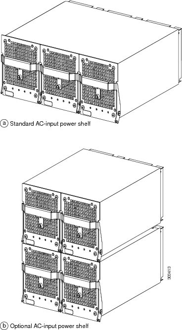
Figure 5-10 identifies the components of the AC power supply.
Figure 5-10 AC Power Supply Components

|
|
Ejector handle |
|
Captive screw |
To remove and replace an AC power supply, use the following procedure.
Step 1 ![]() Unplug the power supply cord from its AC outlet.
Unplug the power supply cord from its AC outlet.
Step 2 ![]() Power off the circuit breaker assigned to that AC outlet.
Power off the circuit breaker assigned to that AC outlet.
|
Warning |
Step 3 ![]() Remove the PEM from the power shelf (Figure 5-11):
Remove the PEM from the power shelf (Figure 5-11):
a. ![]() Loosen the captive screw to release the ejector handle.
Loosen the captive screw to release the ejector handle.
b. ![]() Pivot the ejector handle down to eject the power supply from its backplane connector.
Pivot the ejector handle down to eject the power supply from its backplane connector.
c. ![]() Slide the power supply out of its bay while supporting it with your other hand.
Slide the power supply out of its bay while supporting it with your other hand.
Figure 5-11 Removing an AC Power Supply

Step 4 ![]() Install the new power supply (Figure 5-12):
Install the new power supply (Figure 5-12):
a. ![]() Slide the power supply into the bay until it mates with its backplane connector.
Slide the power supply into the bay until it mates with its backplane connector.
b. ![]() Lift up the ejector handle to hook it over the bottom edge of the power shelf.
Lift up the ejector handle to hook it over the bottom edge of the power shelf.
c. ![]() Tighten the captive screw to secure the power supply in the shelf.
Tighten the captive screw to secure the power supply in the shelf.
Figure 5-12 Installing an AC Power Supply

Step 5 ![]() Plug the power supply cable into its AC outlet.
Plug the power supply cable into its AC outlet.
Step 6 ![]() Power on the circuit breaker to that AC outlet.
Power on the circuit breaker to that AC outlet.
After the power-on sequence completes, the (green) PWR OK indicator on the front of the power supply should light. If the indicator does not light, see the "Troubleshooting an AC Power Supply" section.
Removing and Replacing the Standard AC-Input Power Shelf
Use the following procedure to remove and replace the standard AC-input power shelf.
Step 1 ![]() Remove all of the power supplies as described in "Removing and Replacing an AC Power Supply" section.
Remove all of the power supplies as described in "Removing and Replacing an AC Power Supply" section.
Step 2 ![]() Disconnect each of the AC power cords from the back panel of the power shelf by lifting the retention clip and unplugging the cord (Figure 5-13).
Disconnect each of the AC power cords from the back panel of the power shelf by lifting the retention clip and unplugging the cord (Figure 5-13).
Figure 5-13 Disconnecting AC Power Cords

Step 3 ![]() Unseat the power shelf from the chassis (Figure 5-14):
Unseat the power shelf from the chassis (Figure 5-14):
a. ![]() Loosen the two captive screws on each side of the power shelf.
Loosen the two captive screws on each side of the power shelf.
b. ![]() Loosen the ejector jackscrew to unseat the power shelf from the power interface panel connectors.
Loosen the ejector jackscrew to unseat the power shelf from the power interface panel connectors.
Figure 5-14 Unseating the Power Shelf

Step 4 ![]() Remove the power shelf by grasping the flanges on each side and slowly pulling the shelf along the chassis track to remove it (Figure 5-15):
Remove the power shelf by grasping the flanges on each side and slowly pulling the shelf along the chassis track to remove it (Figure 5-15):
|
Warning |
Figure 5-15 Removing the AC-Input Power Shelf

Step 5 ![]() Insert the new power shelf halfway into the chassis.
Insert the new power shelf halfway into the chassis.
Step 6 ![]() Connect the power shelf to the chassis power interface panel connectors (Figure 5-16):
Connect the power shelf to the chassis power interface panel connectors (Figure 5-16):
a. ![]() Be sure the holes on each side of the power shelf are aligned with the guide pins on each side of the chassis.
Be sure the holes on each side of the power shelf are aligned with the guide pins on each side of the chassis.
b. ![]() Carefully slide the power shelf into place until its two connectors just mate with the power interface panel connectors.
Carefully slide the power shelf into place until its two connectors just mate with the power interface panel connectors.
Figure 5-16 Connecting the AC-Input Power Shelf

Step 7 ![]() Seat the power shelf to the chassis (Figure 5-17):
Seat the power shelf to the chassis (Figure 5-17):
a. ![]() Tighten the ejector jackscrew.
Tighten the ejector jackscrew.
b. ![]() Tighten the captive screws on each flange.
Tighten the captive screws on each flange.
Figure 5-17 Seating the Power Shelf
Step 8 ![]() Reconnect each of the AC power cords to the back panel of the power shelf and secure them in place with their retention clips (Figure 5-18).
Reconnect each of the AC power cords to the back panel of the power shelf and secure them in place with their retention clips (Figure 5-18).
Figure 5-18 Reconnecting AC Power Cords

Step 9 ![]() Reinstall the power supplies as described in "Removing and Replacing an AC Power Supply" section.
Reinstall the power supplies as described in "Removing and Replacing an AC Power Supply" section.
Removing and Replacing the Optional 2-Level AC-Input Power Shelf
Use the following procedure to remove and replace the optional 2-level AC-input power shelf.
Step 1 ![]() Remove all of the power supplies as described in Removing and Replacing an AC Power Supply.
Remove all of the power supplies as described in Removing and Replacing an AC Power Supply.
Step 2 ![]() Disconnect each of the AC power cords from the back panel of the power shelf by lifting the retention clip and unplugging the cord (Figure 5-19).
Disconnect each of the AC power cords from the back panel of the power shelf by lifting the retention clip and unplugging the cord (Figure 5-19).
Figure 5-19 Disconnecting the AC Power Cords

Step 3 ![]() Loosen the two captive screws on each side of the power shelf.
Loosen the two captive screws on each side of the power shelf.
Step 4 ![]() Loosen the ejector jackscrew to unseat the power shelf from the connectors on the chassis power interface panel.
Loosen the ejector jackscrew to unseat the power shelf from the connectors on the chassis power interface panel.
Step 5 ![]() Remove the power shelf by grasping the flanges on each side and slowly pulling the shelf along the chassis track to remove it (Figure 5-20).
Remove the power shelf by grasping the flanges on each side and slowly pulling the shelf along the chassis track to remove it (Figure 5-20).
|
Warning |
Figure 5-20 Removing the AC-Input Power Shelf

Step 6 ![]() Insert the new power shelf halfway into the chassis.
Insert the new power shelf halfway into the chassis.
Step 7 ![]() Connect the power shelf to the chassis power interface panel connectors (Figure 5-21):
Connect the power shelf to the chassis power interface panel connectors (Figure 5-21):
a. ![]() Be sure the holes on each side of the power shelf are aligned with the guide pins on each side of the chassis.
Be sure the holes on each side of the power shelf are aligned with the guide pins on each side of the chassis.
b. ![]() Carefully slide the power shelf into place until its two connectors just mate with the power interface panel connectors.
Carefully slide the power shelf into place until its two connectors just mate with the power interface panel connectors.
Figure 5-21 Connecting the AC-Input Power Shelf

Step 8 ![]() Install the power shelf by grasping the flanges on each side and slowly sliding the shelf into the chassis along the track (Figure 5-22):
Install the power shelf by grasping the flanges on each side and slowly sliding the shelf into the chassis along the track (Figure 5-22):
a. ![]() Tighten the ejector jackscrew.
Tighten the ejector jackscrew.
b. ![]() Tighten the two captive screws on each flange.
Tighten the two captive screws on each flange.
Figure 5-22 Installing the AC-Input Power Shelf
Step 9 ![]() Reconnect each of the AC power cords to the back panel of the power shelf and secure them in place with their retention clips (Figure 5-23).
Reconnect each of the AC power cords to the back panel of the power shelf and secure them in place with their retention clips (Figure 5-23).
Figure 5-23 Reconnecting AC Power Cords

Step 10 ![]() Reinstall the power supplies as described in "Removing and Replacing an AC Power Supply" section beginning with Step 6.
Reinstall the power supplies as described in "Removing and Replacing an AC Power Supply" section beginning with Step 6.
Upgrading to the Optional AC Power Shelf
Use the following procedure to upgrade your router from the standard, 1-level AC power shelf to an optional, 2-level AC power shelf.
Note ![]() A router with an optional, 2-level power shelf is 77.5 inches (196.85 cm) in height and does not fit into a standard 7-foot rack.
A router with an optional, 2-level power shelf is 77.5 inches (196.85 cm) in height and does not fit into a standard 7-foot rack.
Step 1 ![]() Remove the standard one-level power shelf following the procedures in "Removing and Replacing the Standard AC-Input Power Shelf" section through Step 4.
Remove the standard one-level power shelf following the procedures in "Removing and Replacing the Standard AC-Input Power Shelf" section through Step 4.
Step 2 ![]() Install the optional, 2-level power shelf following the procedures in "Removing and Replacing the Optional 2-Level AC-Input Power Shelf" section beginning with Step 6.
Install the optional, 2-level power shelf following the procedures in "Removing and Replacing the Optional 2-Level AC-Input Power Shelf" section beginning with Step 6.
Step 3 ![]() Replace the old cover with the new cover you received in the upgrade kit.
Replace the old cover with the new cover you received in the upgrade kit.
a. ![]() Hold the front cover by its outside edges and align the four ball studs on the back of the cover with the sockets on the front of the chassis.
Hold the front cover by its outside edges and align the four ball studs on the back of the cover with the sockets on the front of the chassis.
b. ![]() Push in the front cover until all four ball studs snap into their sockets and the front cover is flush against the front of the chassis.
Push in the front cover until all four ball studs snap into their sockets and the front cover is flush against the front of the chassis.
Removing and Replacing a DC PEM
This section contains the procedure to remove and replace an DC PEM from the chassis. Before you begin this procedure, read the "Removing and Replacing an AC Power Supply" section.
Figure 5-24 identifies the components of a DC power supply.
Figure 5-24 DC Power Supply Components

|
|
Handle |
|
Ejector lever |
|
|
Fan |
|
Power switch |
Use the following procedure to remove and replace a DC PEM.
Step 1 ![]() Power off the PEM by switching its circuit breaker off.
Power off the PEM by switching its circuit breaker off.
Step 2 ![]() Power off the DC circuit breaker assigned to that PEM.
Power off the DC circuit breaker assigned to that PEM.
|
Warning |
Step 3 ![]() Loosen the captive screw on the ejector handle and pivot the lever down to eject the PEM from its bay (Figure 5-25).
Loosen the captive screw on the ejector handle and pivot the lever down to eject the PEM from its bay (Figure 5-25).
Step 4 ![]() Remove the PEM from the power shelf (Figure 5-25):
Remove the PEM from the power shelf (Figure 5-25):
a. ![]() Pull the PEM halfway out of its bay.
Pull the PEM halfway out of its bay.
b. ![]() Slide the PEM out of its bay while supporting it with your other hand.
Slide the PEM out of its bay while supporting it with your other hand.
|
Warning |
Figure 5-25 Removing a DC PEM

Step 5 ![]() Install the new DC PEM into the power shelf (Figure 5-26):
Install the new DC PEM into the power shelf (Figure 5-26):
a. ![]() Slide the PEM halfway into the chassis.
Slide the PEM halfway into the chassis.
b. ![]() Slowly push the power supply into the chassis until it mates with the backplane connector at the back of the bay.
Slowly push the power supply into the chassis until it mates with the backplane connector at the back of the bay.
c. ![]() Position the bottom of the ejector lever in the slot on the bottom of the power shelf and lift the ejector lever into place to seat the PEM to the backplane connector.
Position the bottom of the ejector lever in the slot on the bottom of the power shelf and lift the ejector lever into place to seat the PEM to the backplane connector.
d. ![]() Tighten the captive screw to secure the PEM in the power shelf.
Tighten the captive screw to secure the PEM in the power shelf.
Note ![]() Because the PEM is powered redundantly by other PEMs in its power load zone, the fault indicator may go on. This can happen even if the circuit breaker for that PEM is switched off, or if there is no DC source power to the PEM. When power is supplied to the PEM and the circuit breaker is switched on, the fault indicator should go off and the PWR OK indicator should light.
Because the PEM is powered redundantly by other PEMs in its power load zone, the fault indicator may go on. This can happen even if the circuit breaker for that PEM is switched off, or if there is no DC source power to the PEM. When power is supplied to the PEM and the circuit breaker is switched on, the fault indicator should go off and the PWR OK indicator should light.
Figure 5-26 Installing a DC PEM

Step 6 ![]() Power on the DC circuit breaker assigned to that PEM.
Power on the DC circuit breaker assigned to that PEM.
Step 7 ![]() Power on the PEM by switching on its circuit breaker.
Power on the PEM by switching on its circuit breaker.
After the power-on sequence completes, the (green) PWR OK indicator on the front of the PEM should light. If the indicator does not light, see the "Troubleshooting a DC Power Supply" section.
Removing and Replacing the DC Power Shelf
Use the following procedure to remove and replace the DC-input power shelf.
Step 1 ![]() Remove all of the DC PEMs as described in the "Removing and Replacing a DC PEM" procedure through Step 4.
Remove all of the DC PEMs as described in the "Removing and Replacing a DC PEM" procedure through Step 4.
Step 2 ![]() Remove the power cable cover by loosening its retaining screw (Figure 5-27).
Remove the power cable cover by loosening its retaining screw (Figure 5-27).
Figure 5-27 Removing the Source DC Power Cable Cover

Step 3 ![]() Measure the voltage across each pair of positive (+) and negative (-) terminals of the power shelf to be sure they are not receiving power.
Measure the voltage across each pair of positive (+) and negative (-) terminals of the power shelf to be sure they are not receiving power.
•![]() All readings should be 0 VDC.
All readings should be 0 VDC.
|
Warning |
Step 4 ![]() Disconnect each pair of power cables and the ground cable from the DC-input terminal studs as follows (Figure 5-28):
Disconnect each pair of power cables and the ground cable from the DC-input terminal studs as follows (Figure 5-28):
|
Warning |
Beginning with terminal studs A1 (Figure 5-28):
a. ![]() Remove the nut and washer from the negative (-) terminal studs and disconnect the cable.
Remove the nut and washer from the negative (-) terminal studs and disconnect the cable.
•![]() Label the cable. For example: A1-.
Label the cable. For example: A1-.
b. ![]() Remove the nut and washer from the positive (+) terminal studs and disconnect the cable.
Remove the nut and washer from the positive (+) terminal studs and disconnect the cable.
•![]() Label the cable. For example: A1+.
Label the cable. For example: A1+.
Repeat steps a. and b. for the remaining pairs of terminal studs.
c. ![]() After all power cables are disconnected, remove the nut and washer from the ground terminal studs and disconnect the ground cable.
After all power cables are disconnected, remove the nut and washer from the ground terminal studs and disconnect the ground cable.
•![]() Label the cable as "ground".
Label the cable as "ground".
Figure 5-28 Disconnecting the Source DC Power Cables

Step 5 ![]() Unseat the power shelf from the chassis (Figure 5-29):
Unseat the power shelf from the chassis (Figure 5-29):
a. ![]() Loosen the two captive screws on each side of the power shelf.
Loosen the two captive screws on each side of the power shelf.
b. ![]() Loosen the ejector jackscrew to unseat the power shelf from the connectors on the chassis power interface panel.
Loosen the ejector jackscrew to unseat the power shelf from the connectors on the chassis power interface panel.
|
Warning |
Figure 5-29 Unseating the Power Shelf
Step 6 ![]() Remove the power shelf by grasping the flanges on each side and slowly pulling the shelf along the chassis track to remove it (Figure 5-30):
Remove the power shelf by grasping the flanges on each side and slowly pulling the shelf along the chassis track to remove it (Figure 5-30):
Figure 5-30 Removing the DC-Input Power Shelf
Step 7 ![]() Insert the new power shelf halfway into the chassis.
Insert the new power shelf halfway into the chassis.
Step 8 ![]() Connect the power shelf to the chassis power interface panel connectors (Figure 5-31):
Connect the power shelf to the chassis power interface panel connectors (Figure 5-31):
a. ![]() Be sure the holes on each side of the power shelf are aligned with the guide pins on each side of the chassis.
Be sure the holes on each side of the power shelf are aligned with the guide pins on each side of the chassis.
b. ![]() Carefully slide the power shelf into place until its two connectors just mate with the power interface panel connectors.
Carefully slide the power shelf into place until its two connectors just mate with the power interface panel connectors.
Figure 5-31 Connecting the DC-Input Power Shelf

Step 9 ![]() Seat the power shelf to the chassis (Figure 5-32):
Seat the power shelf to the chassis (Figure 5-32):
a. ![]() Tighten the ejector jackscrew.
Tighten the ejector jackscrew.
b. ![]() Tighten the captive screws on each flange.
Tighten the captive screws on each flange.
|
Warning |
Figure 5-32 Seating the DC-Input Power Shelf
Step 10 ![]() Reconnect the ground and each pair of power cables to the DC-input terminal studs as follows (Figure 5-33):
Reconnect the ground and each pair of power cables to the DC-input terminal studs as follows (Figure 5-33):
|
Warning |
a. ![]() Reconnect the ground cable to the ground terminal studs.
Reconnect the ground cable to the ground terminal studs.
Beginning with terminal studs B2:
b. ![]() Reconnect the positive cable to the positive (+) terminal studs. For example: B2+.
Reconnect the positive cable to the positive (+) terminal studs. For example: B2+.
c. ![]() Reconnect the negative cable to the negative (-) terminal studs. For example: B2-.
Reconnect the negative cable to the negative (-) terminal studs. For example: B2-.
Repeat steps b and c for the remaining pairs of terminal studs.
Figure 5-33 Reconnecting the Source DC Power Cables to the Power Shelf

Step 11 ![]() Power on the source DC circuit breakers for the PEMs.
Power on the source DC circuit breakers for the PEMs.
Step 12 ![]() Verify the polarity and voltage readings across the pairs of positive and negative terminal studs:
Verify the polarity and voltage readings across the pairs of positive and negative terminal studs:
•![]() All voltage readings should be -48 to -60 VDC
All voltage readings should be -48 to -60 VDC
Step 13 ![]() Reinstall the power cable cover (Figure 5-34).
Reinstall the power cable cover (Figure 5-34).
Figure 5-34 Reinstalling the Source DC Power Cable Cover
Step 14 ![]() Power off the source DC circuit breakers for the PEMs.
Power off the source DC circuit breakers for the PEMs.
Step 15 ![]() Install all of the DC PEMs as described in the "Removing and Replacing a DC PEM" procedure beginning with Step 5.
Install all of the DC PEMs as described in the "Removing and Replacing a DC PEM" procedure beginning with Step 5.
Removing and Replacing Cards from the Chassis
This section contains the procedures to remove cards from the card cages in the chassis. For additional information about specific types of cards, see Chapter 1 "Product Overview".
Removing and Replacing RP and Line Cards from the Upper and Lower Card Cages
This section describes the procedures for removing and installing a router processor (RP) card or a line card from the upper or lower card cage. The upper and lower card cages have 9 slots, and the lower card cage is a reverse image of the top card cage. Alarm cards can only be installed in their specific slots which are labeled as "Alarm Card".
Use the following procedure to remove and replace a line card or RP from the card cage:
Step 1 ![]() Disconnect any cables from the card.
Disconnect any cables from the card.
Step 2 ![]() Remove the card:
Remove the card:
a. ![]() Loosen the captive screws at the top and bottom of the front panel (Figure 5-35a).
Loosen the captive screws at the top and bottom of the front panel (Figure 5-35a).
b. ![]() Pivot the ejector levers to unseat the card from the backplane connector (Figure 5-35b.)
Pivot the ejector levers to unseat the card from the backplane connector (Figure 5-35b.)
c. ![]() Slide the card out of the slot (Figure 5-35c) and place it directly into an antistatic bag or other ESD-preventive container.
Slide the card out of the slot (Figure 5-35c) and place it directly into an antistatic bag or other ESD-preventive container.
Figure 5-35 Removing a Line Card from the Line Card and RP Card Cage

Step 3 ![]() Replace the card by reversing the procedures in Steps 1 and 2.
Replace the card by reversing the procedures in Steps 1 and 2.
Removing and Replacing an Alarm Card
The router is equipped with two alarm cards. One card occupies the dedicated far left slot of the upper card cage; the second occupies the dedicated far right slot of the lower card cage (see Figure 5-36).
The alarm card slot differs from the rest of the card cage slots: it is physically narrower, has a different backplane connector, and is labeled as an "Alarm Card" slot. Alarm cards can only be installed in these two slots.
Figure 5-36 Alarm Card Locations in the Upper and Lower Card Cages

Use the following procedure to remove and replace an alarm card from either the top or bottom card cage.
Step 1 ![]() Disconnect any cables from the alarm card.
Disconnect any cables from the alarm card.
Step 2 ![]() Remove the alarm card:
Remove the alarm card:
a. ![]() Loosen the captive screws at the top and bottom of the front panel (Figure 5-37a).
Loosen the captive screws at the top and bottom of the front panel (Figure 5-37a).
b. ![]() Pull the card out of the slot (Figure 5-37b) and place it directly into an antistatic bag or other ESD-preventive container.
Pull the card out of the slot (Figure 5-37b) and place it directly into an antistatic bag or other ESD-preventive container.
Figure 5-37 Removing an Alarm Card from the Upper Card Cage

Step 3 ![]() Replace the card by reversing the procedures in Steps 1 and 2.
Replace the card by reversing the procedures in Steps 1 and 2.
Removing and Replacing Switch Fabric Cards
The switch fabric card cage is located behind the air filter door on the front of the chassis. The card cage has five keyed, vertical card slots for the CSCs and SFCs. CSCs are installed in the left two card slots (labeled CSC 0 and 1); SFCs are installed in the right three card slots (labeled SFC 0, 1, and 2).
Use the following procedure to remove and replace switch fabric cards.
Step 1 ![]() Loosen the 4 captive screws on the air filter door and pivot the door open (Figure 5-38).
Loosen the 4 captive screws on the air filter door and pivot the door open (Figure 5-38).
Figure 5-38 Opening the Chassis Air Filter Door
Step 2 ![]() Remove the card:
Remove the card:
a. ![]() Pivot the ejector levers to unseat the card from the backplane connector.
Pivot the ejector levers to unseat the card from the backplane connector.
b. ![]() Grasp the card by its metal card carrier and slide the card out of the slot (Figure 5-39).
Grasp the card by its metal card carrier and slide the card out of the slot (Figure 5-39).
–![]() Place the card directly into an antistatic bag or other ESD-preventive container.
Place the card directly into an antistatic bag or other ESD-preventive container.
Figure 5-39 Removing a Card from the Switch Fabric Card Cage

Step 3 ![]() To install the card, reverse the procedure in Step 2.
To install the card, reverse the procedure in Step 2.
Step 4 ![]() Close the air filter door and tighten the captive screws.
Close the air filter door and tighten the captive screws.
Removing and Installing a Chassis
This section provides the procedures to remove and replace a chassis. You may need to perform this procedure to replace a defective chassis or move it to another location. These instructions include the steps directing you to removal and replacement instructions for individual components such as power supplies and line cards.
Because you are removing all the components (except the air filter) from the defective chassis and then reinstalling them in the replacement chassis, the procedures that follow are based on the following prerequisites:
•![]() The replacement chassis, mounted on its own scissor-jack platform, is temporarily placed within reach of the rack in which the defective chassis is installed, and is temporarily connected to the same grounding system as the defective chassis.
The replacement chassis, mounted on its own scissor-jack platform, is temporarily placed within reach of the rack in which the defective chassis is installed, and is temporarily connected to the same grounding system as the defective chassis.
•![]() A spare scissor-jack platform with the anchor clips and bolts (that came with the original chassis) is available to remove the defective chassis from the equipment rack.
A spare scissor-jack platform with the anchor clips and bolts (that came with the original chassis) is available to remove the defective chassis from the equipment rack.
•![]() Components are transferred from the defective chassis directly to the replacement chassis.
Components are transferred from the defective chassis directly to the replacement chassis.
•![]() The replacement chassis is installed in the equipment rack after all components are installed.
The replacement chassis is installed in the equipment rack after all components are installed.
This approach has the advantage of protecting system components against damage by eliminating the need to store them, even temporarily, outside their card cages. It also helps ensure that the physical configuration of the router is maintained because each transferred component is installed in the same location in the replacement chassis that it occupied in the defective chassis.
Procedures for removing and installing the chassis are described in the following sections:
•![]() Preparing the Replacement Chassis
Preparing the Replacement Chassis
•![]() Preparing the Installed Chassis for Removal
Preparing the Installed Chassis for Removal
•![]() Removing and Installing System Components
Removing and Installing System Components
•![]() Removing and Installing System Components
Removing and Installing System Components
•![]() Removing the Chassis from the Equipment Rack
Removing the Chassis from the Equipment Rack
•![]() Installing the Replacement Chassis
Installing the Replacement Chassis
Preparing the Replacement Chassis
Before you can begin to install components in the replacement chassis, you need to temporarily connect the central office grounding system or interior equipment grounding system. You can make this connection when the replacement chassis and scissor-jack platform has been placed near the rack site.
See "NEBS Supplemental Unit Bonding and Grounding Guidelines" section for information about making these connections.
Preparing the Installed Chassis for Removal
Use the following procedure to prepare the installed chassis for removal.
Step 1 ![]() Power off the router (see Powering Off the Router).
Power off the router (see Powering Off the Router).
Step 2 ![]() Power off the circuit breakers to the power supplies.
Power off the circuit breakers to the power supplies.
Step 3 ![]() Disconnect the power cords from the power shelf:
Disconnect the power cords from the power shelf:
•![]() For a standard AC power shelf, see Step 2 of Removing and Replacing the Standard AC-Input Power Shelf.
For a standard AC power shelf, see Step 2 of Removing and Replacing the Standard AC-Input Power Shelf.
•![]() For an optional AC power shelf, see Step 2 of Removing and Replacing the Optional 2-Level AC-Input Power Shelf.
For an optional AC power shelf, see Step 2 of Removing and Replacing the Optional 2-Level AC-Input Power Shelf.
•![]() For a DC power shelf, see Steps 2, 3, and 4 of Removing and Replacing the DC Power Shelf.
For a DC power shelf, see Steps 2, 3, and 4 of Removing and Replacing the DC Power Shelf.
Step 4 ![]() Remove the front doors (see Removing and Installing Front Doors).
Remove the front doors (see Removing and Installing Front Doors).
Step 5 ![]() Disconnect RP cables connected to the console port, auxiliary port, or either of the Ethernet ports, RJ-45 or MII.
Disconnect RP cables connected to the console port, auxiliary port, or either of the Ethernet ports, RJ-45 or MII.
Label each of the RP cables before you disconnect the cables.
Step 6 ![]() Disconnect the cables from each alarm card.
Disconnect the cables from each alarm card.
Label each of the alarm card cables before you disconnect them.
Step 7 ![]() Disconnect the line card interface cables:
Disconnect the line card interface cables:
a. ![]() Identify the type of line card and its slot number. Write this information on a piece of paper before you disconnect the cables. You'll need this information when you reinstall the line cards.
Identify the type of line card and its slot number. Write this information on a piece of paper before you disconnect the cables. You'll need this information when you reinstall the line cards.
b. ![]() Identify the line card cable and its port connection. Label the cable with this information.
Identify the line card cable and its port connection. Label the cable with this information.
c. ![]() Loosen the captive screw at each end of the line card cable-management bracket and pull the cable-management bracket away from the line card.
Loosen the captive screw at each end of the line card cable-management bracket and pull the cable-management bracket away from the line card.
d. ![]() Carefully remove the cables from the cable tray and carefully place the cable bundle out of the way.
Carefully remove the cables from the cable tray and carefully place the cable bundle out of the way.
e. ![]() Repeat steps a through d for each line card.
Repeat steps a through d for each line card.
Step 8 ![]() Remove the vertical cable-management troughs (see Attaching the Vertical Cable-Management Trough).
Remove the vertical cable-management troughs (see Attaching the Vertical Cable-Management Trough).
Removing and Installing System Components
Use the following procedure to remove and install system components from one chassis to another.
Step 1 ![]() Remove the blower modules and then install them into the replacement chassis. (see the "Removing and Replacing Blower Modules" section).
Remove the blower modules and then install them into the replacement chassis. (see the "Removing and Replacing Blower Modules" section).
Step 2 ![]() Remove the power supplies and the power shelf and then install them into the replacement chassis (see "Removing and Replacing AC and DC Power Subsystem Components" section).
Remove the power supplies and the power shelf and then install them into the replacement chassis (see "Removing and Replacing AC and DC Power Subsystem Components" section).
Step 3 ![]() Remove the cards from all three card cages and then install them into the replacement chassis (see "Removing and Replacing Cards from the Chassis" section).
Remove the cards from all three card cages and then install them into the replacement chassis (see "Removing and Replacing Cards from the Chassis" section).
Removing the Chassis from the Equipment Rack
Use the following procedure to remove the chassis from the equipment rack.
|
Warning |
Step 1 ![]() Remove all grounding connections to the chassis (See "NEBS Supplemental Unit Bonding and Grounding Guidelines" section).
Remove all grounding connections to the chassis (See "NEBS Supplemental Unit Bonding and Grounding Guidelines" section).
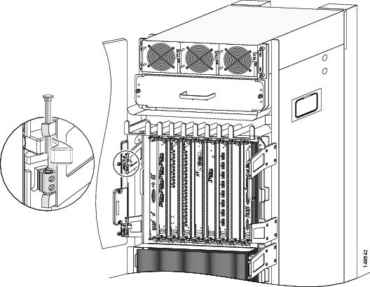
Step 2 ![]() Position the scissor-jack platform from the original router shipping package in front of the rack-mounting platform in the rack (Figure 5-40).
Position the scissor-jack platform from the original router shipping package in front of the rack-mounting platform in the rack (Figure 5-40).
Step 3 ![]() Turn the scissor-jack screw counterclockwise to slowly raise the top of the scissor-jack platform to the same height as the top of the rack-mounting platform. (Figure 5-40.)
Turn the scissor-jack screw counterclockwise to slowly raise the top of the scissor-jack platform to the same height as the top of the rack-mounting platform. (Figure 5-40.)
Figure 5-40 Positioning the Scissor-Jack Platform to Extract the Chassis

Step 4 ![]() Working from the top of the chassis down, remove the screws that secure the chassis to the mounting flanges on the rack (Figure 5-41).
Working from the top of the chassis down, remove the screws that secure the chassis to the mounting flanges on the rack (Figure 5-41).
•![]() Set the screws aside for use to install the replacement chassis.
Set the screws aside for use to install the replacement chassis.
|
Warning |
Figure 5-41 Removing the Mounting Screws

Step 5 ![]() Position one person in front of the chassis to support and guide it while the second person slowly pushes the chassis to slide it off the rack-mounting table and onto the scissor-jack platform.
Position one person in front of the chassis to support and guide it while the second person slowly pushes the chassis to slide it off the rack-mounting table and onto the scissor-jack platform.
Step 6 ![]() Install the four chassis anchor clips through the slots in the bottom of the chassis:
Install the four chassis anchor clips through the slots in the bottom of the chassis:
|
Warning |
a. ![]() Align the holes with the bolt holes in the platform.
Align the holes with the bolt holes in the platform.
b. ![]() Insert and tighten the four bolts to prevent the chassis from shifting on the scissor-jack platform (Figure 5-42).
Insert and tighten the four bolts to prevent the chassis from shifting on the scissor-jack platform (Figure 5-42).
Figure 5-42 Securing the Chassis to the Scissor-Jack Platform

Step 7 ![]() Turn the scissor-jack screw clockwise to slowly lower the scissor-jack platform (Figure 5-43).
Turn the scissor-jack screw clockwise to slowly lower the scissor-jack platform (Figure 5-43).
Figure 5-43 Closing the Scissor-Jack Platform to Lower the Chassis

Step 8 ![]() Slide the chassis and scissor-jack platform onto a safety hand truck with outrigger wheels and secure it with the locking safety strap.
Slide the chassis and scissor-jack platform onto a safety hand truck with outrigger wheels and secure it with the locking safety strap.
–![]() Move the chassis to a level solid floor where the chassis can be repackaged for shipping.
Move the chassis to a level solid floor where the chassis can be repackaged for shipping.
–![]() Use the packaging and unpacking instructions that came with the replacement chassis to repack and ship a defective chassis to the factory.
Use the packaging and unpacking instructions that came with the replacement chassis to repack and ship a defective chassis to the factory.
Installing the Replacement Chassis
Use the following procedure to install the replacement rack in the chassis.
Step 1 ![]() Disconnect the temporary ground connections to the replacement chassis.
Disconnect the temporary ground connections to the replacement chassis.
Step 2 ![]() Install the chassis into the rack (see Rack-Mounting the Router Chassis).
Install the chassis into the rack (see Rack-Mounting the Router Chassis).
Step 3 ![]() Connect all ground connections to the chassis (see Supplemental Bonding and Grounding Connections).
Connect all ground connections to the chassis (see Supplemental Bonding and Grounding Connections).
Step 4 ![]() Attach the vertical cable management troughs (see Attaching the Vertical Cable-Management Trough).
Attach the vertical cable management troughs (see Attaching the Vertical Cable-Management Trough).
Step 5 ![]() Connect all line card interface cables using the notes and labeling you created when disconnecting them from the defective chassis.
Connect all line card interface cables using the notes and labeling you created when disconnecting them from the defective chassis.
Step 6 ![]() Connect power cables to the router (see Connecting Power to the Power Shelf).
Connect power cables to the router (see Connecting Power to the Power Shelf).
Step 7 ![]() Power on the router.
Power on the router.
Removing and Replacing a Power Bus Board Fuse
There are two user-replaceable fuses on the power bus board inside the power interface panel:
•![]() The fuse labeled F1 protects the MBus controller module.
The fuse labeled F1 protects the MBus controller module.
•![]() The fuse labeled F2 protects the 5.1 VDC bias voltage for the current monitoring (Imon) signal and the voltage monitoring (Vmon) signals on AC power subsystems.
The fuse labeled F2 protects the 5.1 VDC bias voltage for the current monitoring (Imon) signal and the voltage monitoring (Vmon) signals on AC power subsystems.
Note ![]() Fuse F2 is used only in AC-input power shelves. It is not used in DC-input power shelves. Spane fuses can be ordered from Cisco as part number: PWR-2A/125V-FUSE=.
Fuse F2 is used only in AC-input power shelves. It is not used in DC-input power shelves. Spane fuses can be ordered from Cisco as part number: PWR-2A/125V-FUSE=.
Use the following procedure to replace a fuse on the power bus board.
Step 1 ![]() Power off the router.
Power off the router.
|
Warning |
Step 2 ![]() Remove the power bus board MBus access cover by loosening the four captive screws (Figure 5-44).
Remove the power bus board MBus access cover by loosening the four captive screws (Figure 5-44).
Figure 5-44 MBus Controller Access Cover

Step 3 ![]() Remove the fuse from the fuse holder using a non-conducting fuse extraction tool (Figure 5-45).
Remove the fuse from the fuse holder using a non-conducting fuse extraction tool (Figure 5-45).
Step 4 ![]() Insert the replacement fuse using the fuse extraction tool to hold the replacement fuse, align the fuse with the opening in the fuse holder.
Insert the replacement fuse using the fuse extraction tool to hold the replacement fuse, align the fuse with the opening in the fuse holder.
Step 5 ![]() Reinstall the MBus access cover.
Reinstall the MBus access cover.
Step 6 ![]() Power on the router.
Power on the router.
Figure 5-45 Removing and Replacing a Power Bus Board Fuse

Upgrading a Cisco 12000 Series Router to a Cisco XR 12000 Series Router
A Cisco 12416 series router can be upgraded to a Cisco XR 12416 router by updating the line cards and software images. For information on this process, including supported line cards and software upgrade procedures, please refer to the Cisco document, Upgrading a Cisco 12000 Series Router from Cisco IOS Software to Cisco IOS XR Software.
 Feedback