About EtherChannels and Redundant Interfaces
This section describes EtherChannels and Redundant Interfaces.
About Redundant Interfaces (ASA Platform Only)
A logical redundant interface consists of a pair of physical interfaces: an active and a standby interface. When the active interface fails, the standby interface becomes active and starts passing traffic. You can configure a redundant interface to increase the ASA reliability. This feature is separate from device-level failover, but you can configure redundant interfaces as well as device-level failover if desired.
You can configure up to 8 redundant interface pairs.
Redundant Interface MAC Address
The redundant interface uses the MAC address of the first physical interface that you add. If you change the order of the member interfaces in the configuration, then the MAC address changes to match the MAC address of the interface that is now listed first. Alternatively, you can assign a manual MAC address to the redundant interface, which is used regardless of the member interface MAC addresses. When the active interface fails over to the standby, the same MAC address is maintained so that traffic is not disrupted.
About EtherChannels
An 802.3ad EtherChannel is a logical interface (called a port-channel interface) consisting of a bundle of individual Ethernet links (a channel group) so that you increase the bandwidth for a single network. A port channel interface is used in the same way as a physical interface when you configure interface-related features.
You can configure up to 48 EtherChannels, depending on how many interfaces your model supports.
Channel Group Interfaces
Each channel group can have up to 16 active interfaces, except for the Firepower 1000 or 2100, which supports 8 active interfaces. For switches that support only 8 active interfaces, you can assign up to 16 interfaces to a channel group: while only 8 interfaces can be active, the remaining interfaces can act as standby links in case of interface failure. For 16 active interfaces, be sure that your switch supports the feature (for example, the Cisco Nexus 7000 with F2-Series 10 Gigabit Ethernet Module).
All interfaces in the channel group must be the same type and speed. The first interface added to the channel group determines the correct type and speed.
The EtherChannel aggregates the traffic across all the available active interfaces in the channel. The interface is selected using a proprietary hash algorithm, based on source or destination MAC addresses, IP addresses, TCP and UDP port numbers and VLAN numbers.
Connecting to an EtherChannel on Another Device
The device to which you connect the ASA EtherChannel must also support 802.3ad EtherChannels; for example, you can connect to the Catalyst 6500 switch or the Cisco Nexus 7000.
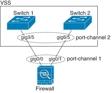
When the switch is part of a Virtual Switching System (VSS) or Virtual Port Channel (vPC), then you can connect ASA interfaces within the same EtherChannel to separate switches in the VSS/vPC. The switch interfaces are members of the same EtherChannel port-channel interface, because the separate switches act like a single switch.

 Note |
If the ASA is in transparent firewall mode, and you place the ASA between two sets of VSS/vPC switches, then be sure to disable Unidirectional Link Detection (UDLD) on any switch ports connected to the ASA with an EtherChannel. If you enable UDLD, then a switch port may receive UDLD packets sourced from both switches in the other VSS/vPC pair. The receiving switch will place the receiving interface in a down state with the reason "UDLD Neighbor mismatch". |
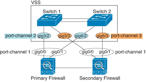
If you use the ASA in an Active/Standby failover deployment, then you need to create separate EtherChannels on the switches in the VSS/vPC, one for each ASA. On each ASA, a single EtherChannel connects to both switches. Even if you could group all switch interfaces into a single EtherChannel connecting to both ASA (in this case, the EtherChannel will not be established because of the separate ASA system IDs), a single EtherChannel would not be desirable because you do not want traffic sent to the standby ASA.

Link Aggregation Control Protocol
The Link Aggregation Control Protocol (LACP) aggregates interfaces by exchanging the Link Aggregation Control Protocol Data Units (LACPDUs) between two network devices.
You can configure each physical interface in an EtherChannel to be:
-
Active—Sends and receives LACP updates. An active EtherChannel can establish connectivity with either an active or a passive EtherChannel. You should use the active mode unless you need to minimize the amount of LACP traffic.
-
Passive—Receives LACP updates. A passive EtherChannel can only establish connectivity with an active EtherChannel. Not supported on Firepower hardware models.
-
On—The EtherChannel is always on, and LACP is not used. An “on” EtherChannel can only establish a connection with another “on” EtherChannel.
LACP coordinates the automatic addition and deletion of links to the EtherChannel without user intervention. It also handles misconfigurations and checks that both ends of member interfaces are connected to the correct channel group. “On” mode cannot use standby interfaces in the channel group when an interface goes down, and the connectivity and configurations are not checked.
Load Balancing
The ASA distributes packets to the interfaces in the EtherChannel by hashing the source and destination IP address of the packet (this criteria is configurable). The resulting hash is divided by the number of active links in a modulo operation where the resulting remainder determines which interface owns the flow. All packets with a hash_value mod active_links result of 0 go to the first interface in the EtherChannel, packets with a result of 1 go to the second interface, packets with a result of 2 go to the third interface, and so on. For example, if you have 15 active links, then the modulo operation provides values from 0 to 14. For 6 active links, the values are 0 to 5, and so on.
For a spanned EtherChannel in clustering, load balancing occurs on a per ASA basis. For example, if you have 32 active interfaces in the spanned EtherChannel across 8 ASAs, with 4 interfaces per ASA in the EtherChannel, then load balancing only occurs across the 4 interfaces on the ASA.
If an active interface goes down and is not replaced by a standby interface, then traffic is rebalanced between the remaining links. The failure is masked from both Spanning Tree at Layer 2 and the routing table at Layer 3, so the switchover is transparent to other network devices.
EtherChannel MAC Address
All interfaces that are part of the channel group share the same MAC address. This feature makes the EtherChannel transparent to network applications and users, because they only see the one logical connection; they have no knowledge of the individual links.
The port-channel interface uses the lowest numbered channel group interface MAC address as the port-channel MAC address. Alternatively you can manually configure a MAC address for the port-channel interface. In multiple context mode, you can automatically assign unique MAC addresses to shared interfaces, including an EtherChannel port interface. We recommend manually, or in multiple context mode for shared interfaces, automatically configuring a unique MAC address in case the group channel interface membership changes. If you remove the interface that was providing the port-channel MAC address, then the port-channel MAC address changes to the next lowest numbered interface, thus causing traffic disruption.

 Feedback