About ASA Clustering
This section describes the clustering architecture and how it works.
How the Cluster Fits into Your Network
The cluster consists of multiple firewalls acting as a single unit. To act as a cluster, the firewalls need the following infrastructure:
-
Isolated, high-speed backplane network for intra-cluster communication, known as the cluster control link.
-
Management access to each firewall for configuration and monitoring.
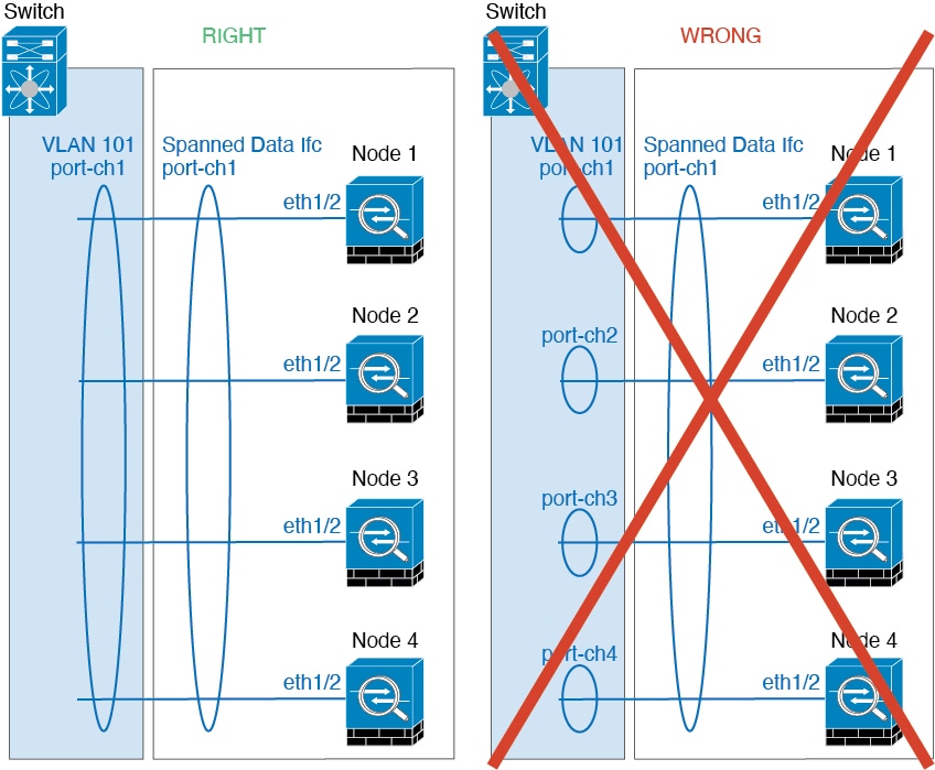
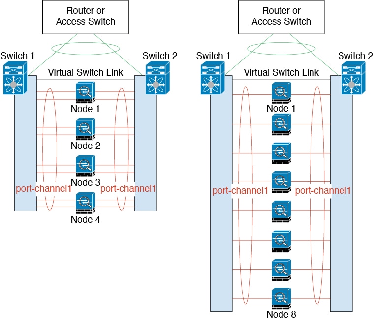
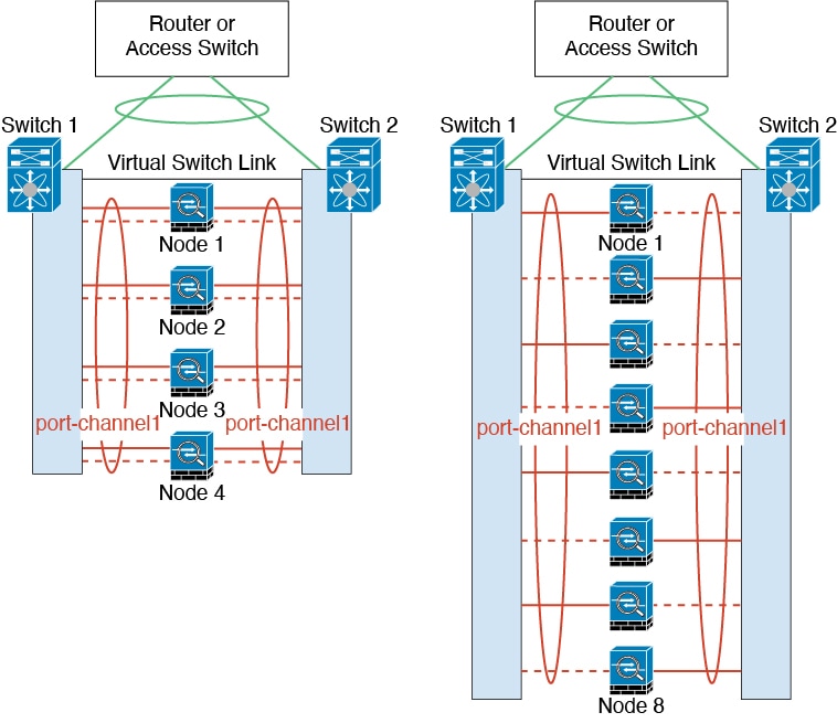
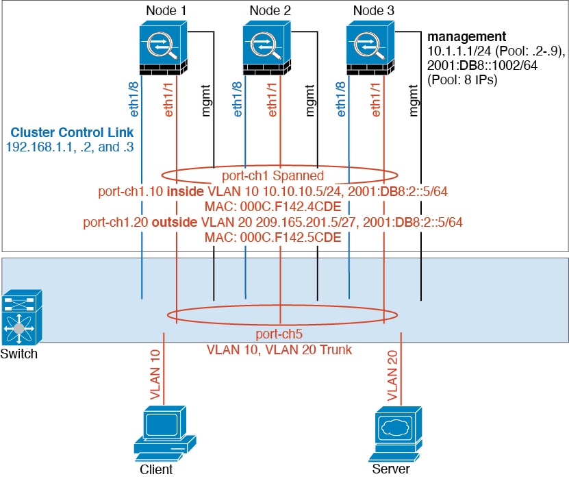
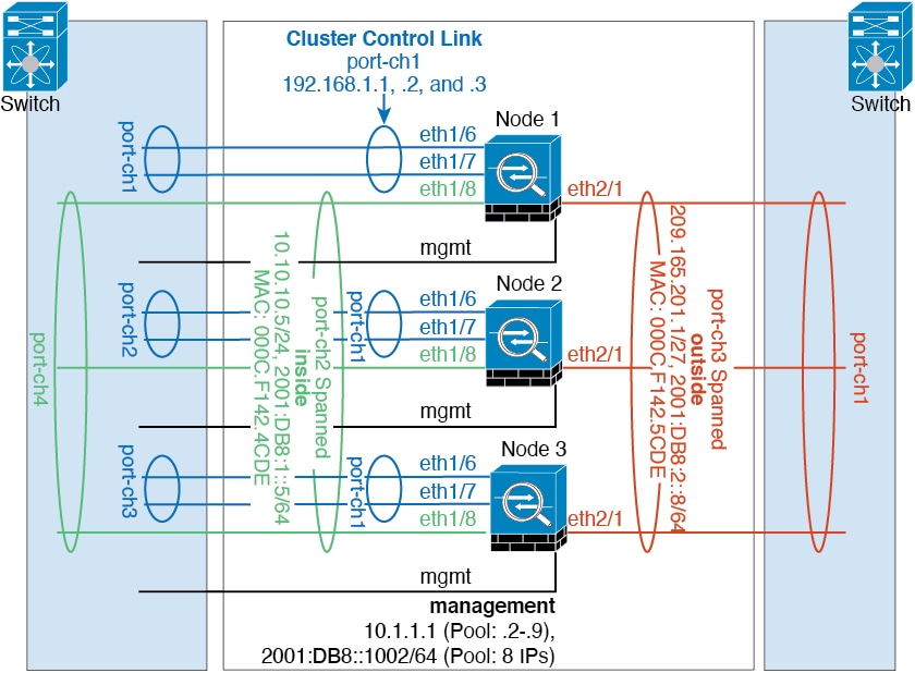
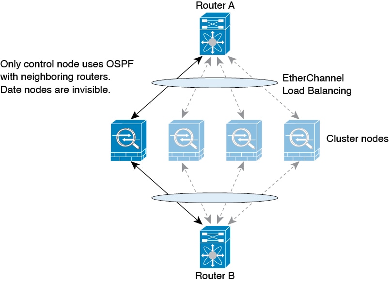
When you place the cluster in your network, the upstream and downstream routers need to be able to load-balance the data coming to and from the cluster using Spanned EtherChannels. Interfaces on multiple members of the cluster are grouped into a single EtherChannel; the EtherChannel performs load balancing between units.
Cluster Members
Cluster members work together to accomplish the sharing of the security policy and traffic flows. This section describes the nature of each member role.
Bootstrap Configuration
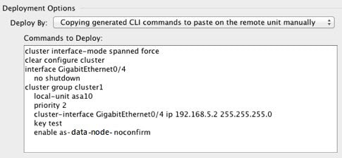
On each device, you configure a minimal bootstrap configuration including the cluster name, cluster control link interface, and other cluster settings. The first node on which you enable clustering typically becomes the control node. When you enable clustering on subsequent nodes, they join the cluster as data nodes.
Control and Data Node Roles
One member of the cluster is the control node. If multiple cluster nodes come online at the same time, the control node is determined by the priority setting in the bootstrap configuration; the priority is set between 1 and 100, where 1 is the highest priority. All other members are data nodes. Typically, when you first create a cluster, the first node you add becomes the control node simply because it is the only node in the cluster so far.
You must perform all configuration (aside from the bootstrap configuration) on the control node only; the configuration is then replicated to the data nodes. In the case of physical assets, such as interfaces, the configuration of the control node is mirrored on all data nodes. For example, if you configure Ethernet 1/2 as the inside interface and Ethernet 1/1 as the outside interface, then these interfaces are also used on the data nodes as inside and outside interfaces.
Some features do not scale in a cluster, and the control node handles all traffic for those features.
Cluster Interfaces
You can configure data interfaces as Spanned EtherChannels. See About Cluster Interfaces for more information.
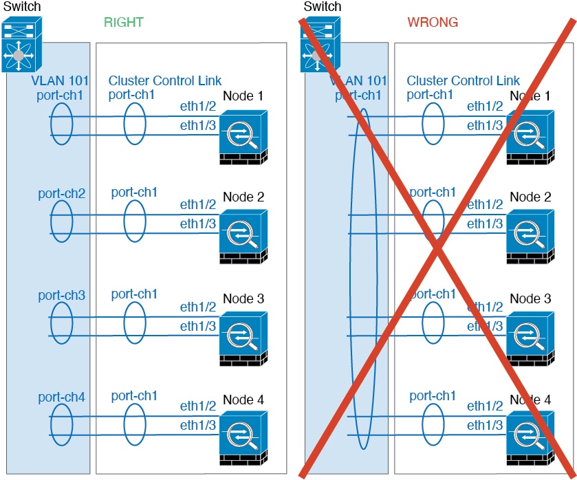
Cluster Control Link
Each unit must dedicate at least one hardware interface as the cluster control link. See Cluster Control Link for more information.
Configuration Replication
All nodes in the cluster share a single configuration. You can only make configuration changes on the control node (with the exception of the bootstrap configuration), and changes are automatically synced to all other nodes in the cluster.
ASA Cluster Management
One of the benefits of using ASA clustering is the ease of management. This section describes how to manage the cluster.
Management Network
We recommend connecting all units to a single management network. This network is separate from the cluster control link.
Management Interface
For the management interface, we recommend using one of the dedicated management interfaces. You can configure the management interfaces as Individual interfaces (for both routed and transparent modes) or as a Spanned EtherChannel interface.
We recommend using Individual interfaces for management. Individual interfaces let you connect directly to each unit if necessary, while a Spanned EtherChannel interface only allows remote connection to the current control unit.
 Note |
You cannot enable dynamic routing for the management interface. You must use a static route. |
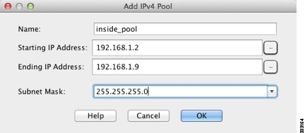
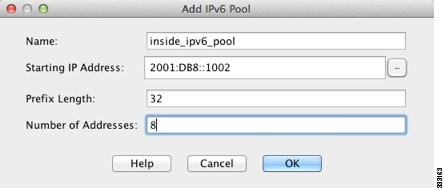
For an Individual interface, the Main cluster IP address is a fixed address for the cluster that always belongs to the current control unit. For each interface, you also configure a range of addresses so that each unit, including the current control unit, can use a Local address from the range. The Main cluster IP address provides consistent management access to an address; when a control unit changes, the Main cluster IP address moves to the new control unit, so management of the cluster continues seamlessly. The Local IP address is used for routing, and is also useful for troubleshooting.
For example, you can manage the cluster by connecting to the Main cluster IP address, which is always attached to the current control unit. To manage an individual member, you can connect to the Local IP address.
For outbound management traffic such as TFTP or syslog, each unit, including the control unit, uses the Local IP address to connect to the server.
For a Spanned EtherChannel interface, you can only configure one IP address, and that IP address is always attached to the control unit. You cannot connect directly to a data unit using the EtherChannel interface; we recommend configuring the management interface as an Individual interface so that you can connect to each unit. Note that you can use a device-local EtherChannel for management.
Control Unit Management Vs. Data Unit Management
All management and monitoring can take place on the control node. From the control node, you can check runtime statistics, resource usage, or other monitoring information of all nodes. You can also issue a command to all nodes in the cluster, and replicate the console messages from data nodes to the control node.
You can monitor data nodes directly if desired. Although also available from the control node, you can perform file management on data nodes (including backing up the configuration and updating images). The following functions are not available from the control node:
-
Monitoring per-node cluster-specific statistics.
-
Syslog monitoring per node (except for syslogs sent to the console when console replication is enabled).
-
SNMP
-
NetFlow
Crypto Key Replication
When you create a crypto key on the control node, the key is replicated to all data nodes. If you have an SSH session to the Main cluster IP address, you will be disconnected if the control node fails. The new control node uses the same key for SSH connections, so that you do not need to update the cached SSH host key when you reconnect to the new control node.
ASDM Connection Certificate IP Address Mismatch
By default, a self-signed certificate is used for the ASDM connection based on the Local IP address. If you connect to the Main cluster IP address using ASDM, then a warning message about a mismatched IP address might appear because the certificate uses the Local IP address, and not the Main cluster IP address. You can ignore the message and establish the ASDM connection. However, to avoid this type of warning, you can enroll a certificate that contains the Main cluster IP address and all the Local IP addresses from the IP address pool. You can then use this certificate for each cluster member. See https://www.cisco.com/c/en/us/td/docs/security/asdm/identity-cert/cert-install.html for more information.
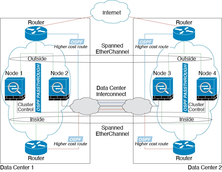
Inter-Site Clustering
For inter-site installations, you can take advantage of ASA clustering as long as you follow the recommended guidelines.
You can configure each cluster chassis to belong to a separate site ID.
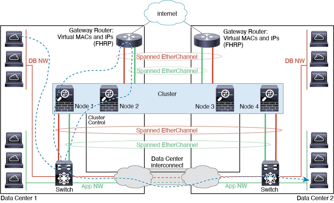
Site IDs work with site-specific MAC addresses and IP addresses. Packets egressing the cluster use a site-specific MAC address and IP address, while packets received by the cluster use a global MAC address and IP address. This feature prevents the switches from learning the same global MAC address from both sites on two different ports, which causes MAC flapping; instead, they only learn the site MAC address. Site-specific MAC addresses and IP address are supported for routed mode using Spanned EtherChannels only.
Site IDs are also used to enable flow mobility using LISP inspection, director localization to improve performance and reduce round-trip time latency for inter-site clustering for data centers, and site redundancy for connections where a backup owner of a traffic flow is always at a different site from the owner.
See the following sections for more information about inter-site clustering:
-
Sizing the Data Center Interconnect—Requirements and Prerequisites for ASA Clustering
-
Inter-Site Guidelines—Guidelines for ASA Clustering
-
Configure Cluster Flow Mobility—Configure Cluster Flow Mobility
-
Enable Director Localization—Configure Basic ASA Cluster Parameters
-
Enable Site Redundancy—Configure Basic ASA Cluster Parameters
-
Inter-Site Examples—Examples for Inter-Site Clustering


 Feedback