Network Address Translation (NAT)

The following topics explain Network Address Translation (NAT) and how to configure it.

Why Use NAT?

Each computer and device within an IP network is assigned a unique IP address that identifies the host. Because of a shortage of public IPv4 addresses, most of these IP addresses are private, not routable anywhere outside of the private company network. RFC 1918 defines the private IP addresses you can use internally that should not be advertised:

  • 10.0.0.0 through 10.255.255.255

  • 172.16.0.0 through 172.31.255.255

  • 192.168.0.0 through 192.168.255.255

One of the main functions of NAT is to enable private IP networks to connect to the Internet. NAT replaces a private IP address with a public IP address, translating the private addresses in the internal private network into legal, routable addresses that can be used on the public Internet. In this way, NAT conserves public addresses because it can be configured to advertise at a minimum only one public address for the entire network to the outside world.

Other functions of NAT include:

  • Security—Keeping internal IP addresses hidden discourages direct attacks.

  • IP routing solutions—Overlapping IP addresses are not a problem when you use NAT.

  • Flexibility—You can change internal IP addressing schemes without affecting the public addresses available externally; for example, for a server accessible to the Internet, you can maintain a fixed IP address for Internet use, but internally, you can change the server address.

  • Translating between IPv4 and IPv6 (Routed mode only) —If you want to connect an IPv6 network to an IPv4 network, NAT lets you translate between the two types of addresses.


Note


NAT is not required. If you do not configure NAT for a given set of traffic, that traffic will not be translated, but will have all of the security policies applied as normal.


NAT Basics

The following topics explain some of the basics of NAT.

NAT Terminology

This document uses the following terminology:

  • Real address/host/network/interface—The real address is the address that is defined on the host, before it is translated. In a typical NAT scenario where you want to translate the inside network when it accesses the outside, the inside network would be the “real” network. Note that you can translate any network connected to the device, not just an inside network. Therefore if you configure NAT to translate outside addresses, “real” can refer to the outside network when it accesses the inside network.

  • Mapped address/host/network/interface—The mapped address is the address that the real address is translated to. In a typical NAT scenario where you want to translate the inside network when it accesses the outside, the outside network would be the “mapped” network.


    Note


    During address translation, IP addresses configured for the device interfaces are not translated.


  • Bidirectional initiation—Static NAT allows connections to be initiated bidirectionally, meaning both to the host and from the host.

  • Source and destination NAT—For any given packet, both the source and destination IP addresses are compared to the NAT rules, and one or both can be translated/untranslated. For static NAT, the rule is bidirectional, so be aware that “source” and “destination” are used in commands and descriptions throughout this guide even though a given connection might originate at the “destination” address.

NAT Types

You can implement NAT using the following methods:

  • Dynamic NAT—A group of real IP addresses are mapped to a (usually smaller) group of mapped IP addresses, on a first come, first served basis. Only the real host can initiate traffic. See Dynamic NAT.

  • Dynamic Port Address Translation (PAT)—A group of real IP addresses are mapped to a single IP address using a unique source port of that IP address. See Dynamic PAT.

  • Static NAT—A consistent mapping between a real and mapped IP address. Allows bidirectional traffic initiation. See Static NAT.

  • Identity NAT—A real address is statically translated to itself, essentially bypassing NAT. You might want to configure NAT this way when you want to translate a large group of addresses, but then want to exempt a smaller subset of addresses. See Identity NAT.

Network Object NAT and Twice NAT

You can implement address translation in two ways: network object NAT and twice NAT.

We recommend using network object NAT unless you need the extra features that twice NAT provides. It is easier to configure network object NAT, and it might be more reliable for applications such as Voice over IP (VoIP). (For VoIP, you might see a failure in the translation of indirect addresses that do not belong to either of the objects used in the rule.)

Network Object NAT

All NAT rules that are configured as a parameter of a network object are considered to be network object NAT rules. This is a quick and easy way to configure NAT for a network object. You cannot create these rules for a group object, however.

After you configure the network object, you can then identify the mapped address for that object, either as an inline address or as another network object or network object group.

When a packet enters an interface, both the source and destination IP addresses are checked against the network object NAT rules. The source and destination address in the packet can be translated by separate rules if separate matches are made. These rules are not tied to each other; different combinations of rules can be used depending on the traffic.

Because the rules are never paired, you cannot specify that sourceA/destinationA should have a different translation than sourceA/destinationB. Use twice NAT for that kind of functionality, where you can identify the source and destination address in a single rule.

Twice NAT

Twice NAT lets you identify both the source and destination address in a single rule. Specifying both the source and destination addresses lets you specify that sourceA/destinationA can have a different translation than sourceA/destinationB.


Note


For static NAT, the rule is bidirectional, so be aware that “source” and “destination” are used in commands and descriptions throughout this guide even though a given connection might originate at the “destination” address. For example, if you configure static NAT with port address translation, and specify the source address as a Telnet server, and you want all traffic going to that Telnet server to have the port translated from 2323 to 23, then you must specify the source ports to be translated (real: 23, mapped: 2323). You specify the source ports because you specified the Telnet server address as the source address.


The destination address is optional. If you specify the destination address, you can either map it to itself (identity NAT), or you can map it to a different address. The destination mapping is always a static mapping.

Comparing Network Object NAT and Twice NAT

The main differences between these two NAT types are:

  • How you define the real address.

    • Network object NAT—You define NAT as a parameter for a network object. A network object names an IP host, range, or subnet so you can then use the object in the NAT configuration instead of the actual IP addresses. The network object IP address serves as the real address. This method lets you easily add NAT to network objects that might already be used in other parts of your configuration.

    • Twice NAT—You identify a network object or network object group for both the real and mapped addresses. In this case, NAT is not a parameter of the network object; the network object or group is a parameter of the NAT configuration. The ability to use a network object group for the real address means that twice NAT is more scalable.

  • How source and destination NAT is implemented.

    • Network Object NAT— Each rule can apply to either the source or destination of a packet. So two rules might be used, one for the source IP address, and one for the destination IP address. These two rules cannot be tied together to enforce a specific translation for a source/destination combination.

    • Twice NAT—A single rule translates both the source and destination. A packet matches one rule only, and further rules are not checked. Even if you do not configure the optional destination address, a matching packet still matches one twice NAT rule only. The source and destination are tied together, so you can enforce different translations depending on the source/destination combination. For example, sourceA/destinationA can have a different translation than sourceA/destinationB.

  • Order of NAT Rules.

    • Network Object NAT—Automatically ordered in the NAT table.

    • Twice NAT—Manually ordered in the NAT table (before or after network object NAT rules).

NAT Rule Order

Network Object NAT and twice NAT rules are stored in a single table that is divided into three sections. Section 1 rules are applied first, then section 2, and finally section 3, until a match is found. For example, if a match is found in section 1, sections 2 and 3 are not evaluated. The following table shows the order of rules within each section.


Note


There is also a Section 0, which contains any NAT rules that the system creates for its own use. These rules have priority over all others. The system automatically creates these rules and clears xlates as needed. You cannot add, edit, or modify rules in Section 0.


Table 1. NAT Rule Table

Table Section

Rule Type

Order of Rules within the Section

Section 1

Twice NAT

Applied on a first match basis, in the order they appear in the configuration. Because the first match is applied, you must ensure that specific rules come before more general rules, or the specific rules might not be applied as desired. By default, twice NAT rules are added to section 1.

By "specific rules first," we mean:

  • Static rules should come before dynamic rules.

  • Rules that include destination translation should come before rules with source translation only.

If you cannot eliminate overlapping rules, where more than one rule might apply based on the source or destination address, be especially careful to follow these recommendations.

Section 2

Network Object NAT

If a match in section 1 is not found, section 2 rules are applied in the following order:

  1. Static rules.

  2. Dynamic rules.

Within each rule type, the following ordering guidelines are used:

  1. Quantity of real IP addresses—From smallest to largest. For example, an object with one address will be assessed before an object with 10 addresses.

  2. For quantities that are the same, then the IP address number is used, from lowest to highest. For example, 10.1.1.0 is assessed before 11.1.1.0.

  3. If the same IP address is used, then the name of the network object is used, in alphabetical order. For example, abracadabra is assessed before catwoman.

Section 3

Twice NAT

If a match is still not found, section 3 rules are applied on a first match basis, in the order they appear in the configuration. This section should contain your most general rules. You must also ensure that any specific rules in this section come before general rules that would otherwise apply.

For section 2 rules, for example, you have the following IP addresses defined within network objects:

  • 192.168.1.0/24 (static)

  • 192.168.1.0/24 (dynamic)

  • 10.1.1.0/24 (static)

  • 192.168.1.1/32 (static)

  • 172.16.1.0/24 (dynamic) (object def)

  • 172.16.1.0/24 (dynamic) (object abc)

The resultant ordering would be:

  • 192.168.1.1/32 (static)

  • 10.1.1.0/24 (static)

  • 192.168.1.0/24 (static)

  • 172.16.1.0/24 (dynamic) (object abc)

  • 172.16.1.0/24 (dynamic) (object def)

  • 192.168.1.0/24 (dynamic)

NAT Interfaces

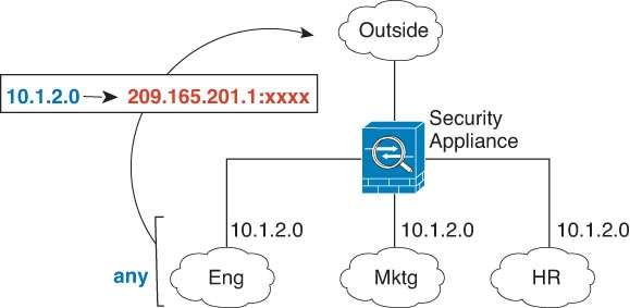
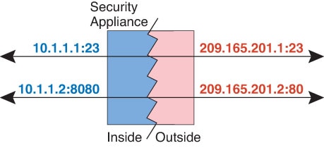
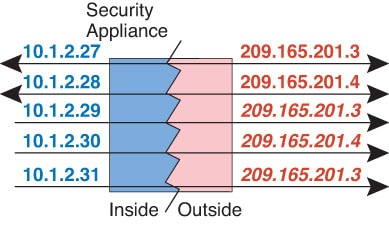
Except for bridge group member interfaces, you can configure a NAT rule to apply to any interface (in other words, all interfaces), or you can identify specific real and mapped interfaces. You can also specify any interface for the real address, and a specific interface for the mapped address, or vice versa.

For example, you might want to specify any interface for the real address and specify the outside interface for the mapped address if you use the same private addresses on multiple interfaces, and you want to translate them all to the same global pool when accessing the outside.

Figure 1. Specifying Any Interface

However, the concept of “any” interface does not apply to bridge group member interfaces. When you specify “any” interface, all bridge group member interfaces are excluded. Thus, to apply NAT to bridge group members, you must specify the member interface. This could result in many similar rules where only one interface is different. You cannot configure NAT for the Bridge Virtual Interface (BVI) itself, you can configure NAT for member interfaces only.

Guidelines for NAT

The following topics provide detailed guidelines for implementing NAT.

Firewall Mode Guidelines for NAT

NAT is supported in routed and transparent firewall mode.

However, configuring NAT on bridge group member interfaces (interfaces that are part of a Bridge Group Virtual Interface, or BVI) has the following restrictions:

  • When configuring NAT for the members of a bridge group, you specify the member interface. You cannot configure NAT for the bridge group interface (BVI) itself.

  • When doing NAT between bridge group member interfaces, you must specify the real and mapped addresses. You cannot specify “any” as the interface.

  • You cannot configure interface PAT when the mapped address is a bridge group member interface, because there is no IP address attached to the interface.

  • You cannot translate between IPv4 and IPv6 networks (NAT64/46) when the source and destination interfaces are members of the same bridge group. Static NAT/PAT 44/66, dynamic NAT44/66, and dynamic PAT44 are the only allowed methods; dynamic PAT66 is not supported. However, you can do NAT64/46 between members of different bridge groups, or between a bridge group member (source) and standard routed interface (destination).

IPv6 NAT Guidelines

NAT supports IPv6 with the following guidelines and restrictions.

  • For standard routed mode interfaces, you can also translate between IPv4 and IPv6.

  • You cannot translate between IPv4 and IPv6 for interfaces that are members of the same bridge group. You can translate between two IPv6 or two IPv4 networks only. This restriction does not apply when the interfaces are members of different bridge groups, or between a bridge group member and a standard routed interface.

  • You cannot use dynamic PAT for IPv6 (NAT66) when translating between interfaces in the same bridge group. This restriction does not apply when the interfaces are members of different bridge groups, or between a bridge group member and a standard routed interface.

  • For static NAT, you can specify an IPv6 subnet up to /64. Larger subnets are not supported.

  • When using FTP with NAT46, when an IPv4 FTP client connects to an IPv6 FTP server, the client must use either the extended passive mode (EPSV) or extended port mode (EPRT); PASV and PORT commands are not supported with IPv6.

IPv6 NAT Best Practices

You can use NAT to translate between IPv6 networks, and also to translate between IPv4 and IPv6 networks (routed mode only). We recommend the following best practices:

  • NAT66 (IPv6-to-IPv6)—We recommend using static NAT. Although you can use dynamic NAT or PAT, IPv6 addresses are in such large supply, you do not have to use dynamic NAT. If you do not want to allow returning traffic, you can make the static NAT rule unidirectional (twice NAT only).

  • NAT46 (IPv4-to-IPv6)—We recommend using static NAT. Because the IPv6 address space is so much larger than the IPv4 address space, you can easily accommodate a static translation. If you do not want to allow returning traffic, you can make the static NAT rule unidirectional (twice NAT only). When translating to an IPv6 subnet (/96 or lower), the resulting mapped address is by default an IPv4-embedded IPv6 address, where the 32-bits of the IPv4 address is embedded after the IPv6 prefix. For example, if the IPv6 prefix is a /96 prefix, then the IPv4 address is appended in the last 32-bits of the address. For example, if you map 192.168.1.0/24 to 201b::0/96, then 192.168.1.4 will be mapped to 201b::0.192.168.1.4 (shown with mixed notation). If the prefix is smaller, such as /64, then the IPv4 address is appended after the prefix, and a suffix of 0s is appended after the IPv4 address. You can also optionally translate the addresses net-to-net, where the first IPv4 address maps to the first IPv6 address, the second to the second, and so on.

  • NAT64 (IPv6-to-IPv4)—You may not have enough IPv4 addresses to accommodate the number of IPv6 addresses. We recommend using a dynamic PAT pool to provide a large number of IPv4 translations.

Additional Guidelines for NAT

  • For interfaces that are members of a bridge group, you write NAT rules for the member interfaces. You cannot write NAT rules for the Bridge Virtual Interface (BVI) itself.

  • You cannot write NAT rules for a Virtual Tunnel Interface (VTI), which are used in site-to-site VPN. Writing rules for the VTI's source interface will not apply NAT to the VPN tunnel. To write NAT rules that will apply to VPN traffic tunneled on a VTI, you must use "any" as the interface; you cannot explicitly specify interface names.

  • (Network Object NAT only.) You can only define a single NAT rule for a given object; if you want to configure multiple NAT rules for an object, you need to create multiple objects with different names that specify the same IP address. For example, object network obj-10.10.10.1-01, object network obj-10.10.10.1-02, and so on.

  • If a VPN is defined on an interface, inbound ESP traffic on the interface is not subject to the NAT rules. The system allows the ESP traffic for established VPN tunnels only, dropping traffic not associated with an existing tunnel. This restriction applies to ESP and UDP ports 500 and 4500.

  • If you define a site-to-site VPN on a device that is behind a device that is applying dynamic PAT, so that UDP ports 500 and 4500 are not the ones actually used, you must initiate the connection from the device that is behind the PAT device. The responder cannot initiate the security association (SA) because it does not know the correct port numbers.

  • If you change the NAT configuration, and you do not want to wait for existing translations to time out before the new NAT configuration is used, you can clear the translation table using the clear xlate command in the device CLI. However, clearing the translation table disconnects all current connections that use translations.

    If you create a new NAT rule that should apply to an existing connection (such as a VPN tunnel), you need to use clear conn to end the connection. Then, the attempt to re-establish the connection should hit the NAT rule and the connection should be NAT'ed correctly.


    Note


    If you remove a dynamic NAT or PAT rule, and then add a new rule with mapped addresses that overlap the addresses in the removed rule, then the new rule will not be used until all connections associated with the removed rule time out or are cleared using the clear xlate or clear conn commands. This safeguard ensures that the same address is not assigned to multiple hosts.


  • When translating SCTP traffic, use static network object NAT only. Dynamic NAT/PAT is not allowed. Although you can configure static twice NAT, this is not recommended because the topology of the destination part of the SCTP association is unknown.

  • Objects and object groups used in NAT cannot be undefined; they must include IP addresses.

  • You cannot use an object group with both IPv4 and IPv6 addresses; the object group must include only one type of address.

  • (Twice NAT only.) When using any as the source address in a NAT rule, the definition of “any” traffic (IPv4 vs. IPv6) depends on the rule. Before the ASA performs NAT on a packet, the packet must be IPv6-to-IPv6 or IPv4-to-IPv4; with this prerequisite, the ASA can determine the value of any in a NAT rule. For example, if you configure a rule from “any” to an IPv6 server, and that server was mapped from an IPv4 address, then any means “any IPv6 traffic.” If you configure a rule from “any” to “any,” and you map the source to the interface IPv4 address, then any means “any IPv4 traffic” because the mapped interface address implies that the destination is also IPv4.

  • You can use the same mapped object or group in multiple NAT rules.

  • The mapped IP address pool cannot include:

    • The mapped interface IP address. If you specify “any” interface for the rule, then all interface IP addresses are disallowed. For interface PAT (routed mode only), specify the interface name instead of the interface address.

    • The failover interface IP address.

    • (Transparent mode.) The management IP address.

    • (Dynamic NAT.) The standby interface IP address when VPN is enabled.

    • Existing VPN pool addresses.

  • Avoid using overlapping addresses in static and dynamic NAT policies. For example, with overlapping addresses, a PPTP connection can fail to get established if the secondary connection for PPTP hits the static instead of dynamic xlate.

  • You cannot use overlapping addresses in the source address of a NAT rule and a remote access VPN address pool.

  • For application inspection limitations with NAT or PAT, see Default Inspections and NAT Limitations.

  • The default behavior for identity NAT has proxy ARP enabled, matching other static NAT rules. You can disable proxy ARP if desired. See Routing NAT Packets for more information.

  • If you enable the arp permit-nonconnected command, the system does not respond to ARP requests if the mapped address is not part of any connected subnet and you also do not specify the mapped interface in the NAT rule (that is, you specify "any" interface). To resolve this problem, specify the mapped interface.

  • If you specify a destination interface in a rule, then that interface is used as the egress interface rather than looking up the route in the routing table. However, for identity NAT, you have the option to use a route lookup instead.

  • If you use PAT on Sun RPC traffic, which is used to connect to NFS servers, be aware that the NFS server might reject connections if the PAT'ed port is above 1024. The default configuration of NFS servers is to reject connections from ports higher than 1024. The error is typically "Permission Denied." Mapping ports above 1024 might happen if you use the "flat range" option to use the higher port numbers if a port in the lower range is not available, especially if you do not select the option to include the lower range in the flat range.Mapping ports above 1024 happens if you do not select the option to include the reserved ports (1-1023) in the port range of a PAT pool. You can avoid this problem by changing the NFS server configuration to allow all port numbers.

  • NAT applies to through traffic only. Traffic generated by the system is not subject to NAT.

  • You can improve system performance and reliability by using the transactional commit model for NAT. See the basic settings chapter in the general operations configuration guide for more information. Use the asp rule-engine transactional-commit nat command.

  • Do not name a network object or group pat-pool, using any combination of upper- or lower-case letters.

  • The unidirectional option is mainly useful for testing purposes and might not work with all protocols. For example, SIP requires protocol inspection to translate SIP headers using NAT, but this will not occur if you make the translation unidirectional.

  • You cannot use NAT on the internal payload of Protocol Independent Multicast (PIM) registers.

  • (Twice NAT) When writing NAT rules for a dual ISP interface setup (primary and backup interfaces using service level agreements in the routing configuration), do not specify destination criteria in the rule. Ensure the rule for the primary interface comes before the rule for the backup interface. This allows the device to choose the correct NAT destination interface based on the current routing state when the primary ISP is unavailable. If you specify destination objects, the NAT rule will always select the primary interface for the otherwise duplicate rules.

  • If you get the ASP drop reason nat-no-xlate-to-pat-pool for traffic that should not match the NAT rules defined for the interface, configure identity NAT rules for the affected traffic so the traffic can pass untranslated.

  • If you configure NAT for GRE tunnel endpoints, you must disable keepalives on the endpoints or the tunnel cannot be established. The endpoints send keepalives to the original addresses.

  • DHCP and BOOTP share ports UDP/67-68. Because BOOTP is obsolete, writing NAT rules for the bootps port can cause port allocation problems when also running DHCP. Consider using DHCP relay instead for transmitting DHCP requests between network segments.

Network Object NAT Guidelines for Mapped Address Objects

For dynamic NAT, you must use an object or group for the mapped addresses. For the other NAT types, you can use an object or group, or you have the option of using inline addresses. Network object groups are particularly useful for creating a mapped address pool with discontinuous IP address ranges or multiple hosts or subnets. Use the object network and object-group network commands to create the objects.

Consider the following guidelines when creating objects for mapped addresses.

  • A network object group can contain objects or inline addresses of either IPv4 or IPv6 addresses. The group cannot contain both IPv4 and IPv6 addresses; it must contain one type only.

  • See Additional Guidelines for NAT for information about disallowed mapped IP addresses.

  • Do not name a network object or group pat-pool, using any combination of upper- or lower-case letters.

  • Dynamic NAT:

    • You cannot use an inline address; you must configure a network object or group.

    • The object or group cannot contain a subnet; the object must define a range; the group can include hosts and ranges.

    • If a mapped network object contains both ranges and host IP addresses, then the ranges are used for dynamic NAT, and then the host IP addresses are used as a PAT fallback.

  • Dynamic PAT (Hide):

    • Instead of using an object, you can optionally configure an inline host address or specify the interface address.

    • If you use an object, the object or group cannot contain a subnet. The object must define a host, or for a PAT pool, a range. The group (for a PAT pool) can include hosts and ranges.

  • Static NAT or Static NAT with port translation:

    • Instead of using an object, you can configure an inline address or specify the interface address (for static NAT-with-port-translation).

    • If you use an object, the object or group can contain a host, range, or subnet.

  • Identity NAT

    • Instead of using an object, you can configure an inline address.

    • If you use an object, the object must match the real addresses you want to translate.

Twice NAT Guidelines for Real and Mapped Address Objects

For each NAT rule, configure up to four network objects or groups for:

  • Source real address

  • Source mapped address

  • Destination real address

  • Destination mapped address

Objects are required unless you specify the any keyword inline to represent all traffic, or for some types of NAT, the interface keyword to represent the interface address. Network object groups are particularly useful for creating a mapped address pool with discontinuous IP address ranges or multiple hosts or subnets. Use the object network and object-group network commands to create the objects.

Consider the following guidelines when creating objects for twice NAT.

  • A network object group can contain objects or inline addresses of either IPv4 or IPv6 addresses. The group cannot contain both IPv4 and IPv6 addresses; it must contain one type only.

  • See Additional Guidelines for NAT for information about disallowed mapped IP addresses.

  • Do not name a network object or group pat-pool, using any combination of upper- or lower-case letters.

  • Source Dynamic NAT:

    • You typically configure a larger group of real addresses to be mapped to a smaller group.

    • The mapped object or group cannot contain a subnet; the object must define a range; the group can include hosts and ranges.

    • If a mapped network object contains both ranges and host IP addresses, then the ranges are used for dynamic NAT, and the host IP addresses are used as a PAT fallback.

  • Source Dynamic PAT (Hide):

    • If you use an object, the object or group cannot contain a subnet. The object must define a host, or for a PAT pool, a range. The group (for a PAT pool) can include hosts and ranges.

  • Source Static NAT or Static NAT with port translation:

    • The mapped object or group can contain a host, range, or subnet.

    • The static mapping is typically one-to-one, so the real addresses have the same quantity as the mapped addresses. You can, however, have different quantities if desired.

  • Source Identity NAT

    • The real and mapped objects must match. You can use the same object for both, or you can create separate objects that contain the same IP addresses.

  • Destination Static NAT or Static NAT with port translation (the destination translation is always static):

    • Although the main feature of twice NAT is the inclusion of the destination IP address, the destination address is optional. If you do specify the destination address, you can configure static translation for that address or just use identity NAT for it. You might want to configure twice NAT without a destination address to take advantage of some of the other qualities of twice NAT, including the use of network object groups for real addresses, or manually ordering of rules. For more information, see Comparing Network Object NAT and Twice NAT.

    • For identity NAT, the real and mapped objects must match. You can use the same object for both, or you can create separate objects that contain the same IP addresses.

    • The static mapping is typically one-to-one, so the real addresses have the same quantity as the mapped addresses. You can, however, have different quantities if desired.

    • For static interface NAT with port translation (routed mode only), you can specify the interface keyword instead of a network object/group for the mapped address.

    • You can use a fully-qualified domain name, such as www.example.com, as the translated (mapped) destination. For details, see FQDN Destination Guidelines.

FQDN Destination Guidelines

You can specify the translated (mapped) destination in a twice NAT rule using a fully-qualified domain name (FQDN) network object instead of an IP address. For example, you can create a rule based on traffic that is destined for the www.example.com web server.

When using an FQDN, the system obtains the DNS resolution and writes the NAT rule based on the returned address. If you are using multiple DNS server groups, the filter domains are honored and the address is requested from the appropriate group based on the filters. If more than one address is obtained from the DNS server, the address used is based on the following:

  • If there is an address on the same subnet as the specified interface, that address is used. If there isn’t one on the same subnet, the first address returned is used.

  • The IP type for the translated source and translated destination must match. For example, if the translated source address is IPv6, the FQDN object must specify IPv6 as the address type. If the translated source is IPv4, the FQDN object must specify IPv4 as the address type.

You cannot include an FQDN object in a network group that is used for manual NAT destination. In NAT, an FQDN object must be used alone, as only a single destination host makes sense for this type of NAT rule.

If the FQDN cannot be resolved to an IP address, the rule is not functional until a DNS resolution is obtained.

Twice NAT Guidelines for Service Objects for Real and Mapped Ports

You can optionally configure service objects for:

  • Source real port (Static only) or Destination real port

  • Source mapped port (Static only) or Destination mapped port

Use the object service command to create the objects.

Consider the following guidelines when creating objects for twice NAT.

  • NAT supports TCP, UDP, and SCTP only. When translating a port, be sure the protocols in the real and mapped service objects are identical (for example, both TCP). Although you can configure static twice NAT rules with SCTP port specifications, this is not recommended, because the topology of the destination part of the SCTP association is unknown. Use static object NAT instead for SCTP.

  • The “not equal” (neq) operator is not supported.

  • For identity port translation, you can use the same service object for both the real and mapped ports.

  • Source Dynamic NAT—Source Dynamic NAT does not support port translation.

  • Source Dynamic PAT (Hide)—Source Dynamic PAT does not support port translation.

  • Source Static NAT, Static NAT with port translation, or Identity NAT—A service object can contain both a source and destination port; however, you should specify either the source or the destination port for both service objects. You should only specify both the source and destination ports if your application uses a fixed source port (such as some DNS servers); but fixed source ports are rare. For example, if you want to translate the port for the source host, then configure the source service.

  • Destination Static NAT or Static NAT with port translation (the destination translation is always static)—For non-static source NAT, you can only perform port translation on the destination. A service object can contain both a source and destination port, but only the destination port is used in this case. If you specify the source port, it will be ignored.

Dynamic NAT

The following topics explain dynamic NAT and how to configure it.

About Dynamic NAT

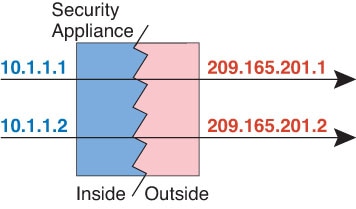
Dynamic NAT translates a group of real addresses to a pool of mapped addresses that are routable on the destination network. The mapped pool typically includes fewer addresses than the real group. When a host you want to translate accesses the destination network, NAT assigns the host an IP address from the mapped pool. The translation is created only when the real host initiates the connection. The translation is in place only for the duration of the connection, and a given user does not keep the same IP address after the translation times out. Users on the destination network, therefore, cannot initiate a reliable connection to a host that uses dynamic NAT, even if the connection is allowed by an access rule.


Note


For the duration of the translation, a remote host can initiate a connection to the translated host if an access rule allows it. Because the address is unpredictable, a connection to the host is unlikely. Nevertheless, in this case you can rely on the security of the access rule. A successful connection from a remote host can reset the idle timer for the connection.


The following figure shows a typical dynamic NAT scenario. Only real hosts can create a NAT session, and responding traffic is allowed back.

Figure 2. Dynamic NAT

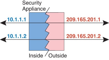
The following figure shows a remote host attempting to initiate a connection to a mapped address. This address is not currently in the translation table; therefore, the packet is dropped.

Figure 3. Remote Host Attempts to Initiate a Connection to a Mapped Address

Dynamic NAT Disadvantages and Advantages

Dynamic NAT has these disadvantages:

  • If the mapped pool has fewer addresses than the real group, you could run out of addresses if the amount of traffic is more than expected.

    Use PAT or a PAT fall-back method if this event occurs often because PAT provides over 64,000 translations using ports of a single address.

  • You have to use a large number of routable addresses in the mapped pool, and routable addresses may not be available in large quantities.

The advantage of dynamic NAT is that some protocols cannot use PAT. PAT does not work with the following:

  • IP protocols that do not have a port to overload, such as GRE version 0.

  • Some multimedia applications that have a data stream on one port, the control path on another port, and are not open standard.

Configure Dynamic Network Object NAT

This section describes how to configure network object NAT for dynamic NAT.

Procedure


Step 1

Create a host or range network object (object network command), or a network object group (object-group network command), for the mapped addresses.

  • The object or group cannot contain a subnet; the object must define a range; the group can include hosts and ranges.

  • If a mapped network object contains both ranges and host IP addresses, then the ranges are used for dynamic NAT, and then the host IP addresses are used as a PAT fallback.

Step 2

Create or edit the network object for which you want to configure NAT: object network obj_name

Example:


hostname(config)# object network my-host-obj1

Step 3

(Skip when editing an object that has the right address.) Define the real IPv4 or IPv6 addresses that you want to translate.

  • host {IPv4_address | IPv6_address}—The IPv4 or IPv6 address of a single host. For example, 10.1.1.1 or 2001:DB8::0DB8:800:200C:417A.

  • subnet {IPv4_address IPv4_mask | IPv6_address/IPv6_prefix}—The address of a network. For IPv4 subnets, include the mask after a space, for example, 10.0.0.0 255.0.0.0. For IPv6, include the address and prefix as a single unit (no spaces), such as 2001:DB8:0:CD30::/60.

  • range start_address end_address—A range of addresses. You can specify IPv4 or IPv6 ranges. Do not include masks or prefixes.

Example:


hostname(config-network-object)# host 10.2.2.2

Step 4

Configure dynamic NAT for the object IP addresses. You can only define a single NAT rule for a given object.

nat [(real_ifc,mapped_ifc)] dynamic mapped_obj [interface [ipv6]] [dns]

Where:

  • Interfaces—(Required for bridge group member interfaces.) Specify the real (real_ifc) and mapped (mapped_ifc) interfaces. Be sure to include the parentheses. In routed mode, if you do not specify the real and mapped interfaces, all interfaces are used. You can also specify the keyword any for one or both of the interfaces, for example (any,outside), but any does not apply to bridge group member interfaces.

  • Mapped IP address—Specify the network object or network object group that includes the mapped IP addresses.

  • Interface PAT fallback—(Optional) The interface keyword enables interface PAT fallback. After the mapped IP addresses are used up, then the IP address of the mapped interface is used. If you specify ipv6, then the IPv6 address of the interface is used. For this option, you must configure a specific interface for the mapped_ifc. (You cannot specify interface when the mapped interface is a bridge group member.)

  • DNS—(Optional) The dns keyword translates DNS replies. Be sure DNS inspection is enabled (it is enabled by default). See Rewriting DNS Queries and Responses Using NAT for more information.

Example:


hostname(config-network-object)# nat (inside,outside) dynamic MAPPED_IPS interface


Examples

The following example configures dynamic NAT that hides the 192.168.2.0 network behind a range of outside addresses 10.2.2.1 through 10.2.2.10:


hostname(config)# object network my-range-obj
hostname(config-network-object)# range 10.2.2.1 10.2.2.10
hostname(config)# object network my-inside-net
hostname(config-network-object)# subnet 192.168.2.0 255.255.255.0
hostname(config-network-object)# nat (inside,outside) dynamic my-range-obj

The following example configures dynamic NAT with dynamic PAT backup. Hosts on inside network 10.76.11.0 are mapped first to the nat-range1 pool (10.10.10.10-10.10.10.20). After all addresses in the nat-range1 pool are allocated, dynamic PAT is performed using the pat-ip1 address (10.10.10.21). In the unlikely event that the PAT translations are also used up, dynamic PAT is performed using the outside interface address.


hostname(config)# object network nat-range1
hostname(config-network-object)# range 10.10.10.10 10.10.10.20

hostname(config-network-object)# object network pat-ip1
hostname(config-network-object)# host 10.10.10.21

hostname(config-network-object)# object-group network nat-pat-grp
hostname(config-network-object)# network-object object nat-range1
hostname(config-network-object)# network-object object pat-ip1

hostname(config-network-object)# object network my_net_obj5
hostname(config-network-object)# subnet 10.76.11.0 255.255.255.0
hostname(config-network-object)# nat (inside,outside) dynamic nat-pat-grp interface

The following example configures dynamic NAT with dynamic PAT backup to translate IPv6 hosts to IPv4. Hosts on inside network 2001:DB8::/96 are mapped first to the IPv4_NAT_RANGE pool (209.165.201.1 to 209.165.201.30). After all addresses in the IPv4_NAT_RANGE pool are allocated, dynamic PAT is performed using the IPv4_PAT address (209.165.201.31). In the event that the PAT translations are also used up, dynamic PAT is performed using the outside interface address.


hostname(config)# object network IPv4_NAT_RANGE
hostname(config-network-object)# range 209.165.201.1 209.165.201.30

hostname(config-network-object)# object network IPv4_PAT
hostname(config-network-object)# host 209.165.201.31

hostname(config-network-object)# object-group network IPv4_GROUP
hostname(config-network-object)# network-object object IPv4_NAT_RANGE
hostname(config-network-object)# network-object object IPv4_PAT

hostname(config-network-object)# object network my_net_obj5
hostname(config-network-object)# subnet 2001:DB8::/96
hostname(config-network-object)# nat (inside,outside) dynamic IPv4_GROUP interface

Configure Dynamic Twice NAT

This section describes how to configure twice NAT for dynamic NAT.

Procedure


Step 1

Create host or range network objects (object network command), or network object groups (object-group network command), for the source real addresses, the source mapped addresses, the destination real addresses, and the destination mapped addresses. You can also use an FQDN network object for the destination mapped address.

  • If you want to translate all source traffic, you can skip adding an object for the source real addresses, and instead specify the any keyword in the nat command.

  • If you want to configure destination static interface NAT with port translation only, you can skip adding an object for the destination mapped addresses, and instead specify the interface keyword in the nat command.

If you do create objects, consider the following guidelines:

  • You typically configure a larger group of real addresses to be mapped to a smaller group.

  • The object or group cannot contain a subnet; the object must define a range; the group can include hosts and ranges.

  • If a mapped network object contains both ranges and host IP addresses, then the ranges are used for dynamic NAT, and then the host IP addresses are used as a PAT fallback.

Step 2

(Optional.) Create service objects for the destination real ports and the destination mapped ports.

For dynamic NAT, you can only perform port translation on the destination. A service object can contain both a source and destination port, but only the destination port is used in this case. If you specify the source port, it will be ignored.

Step 3

Configure dynamic NAT.

nat [(real_ifc ,mapped_ifc )] [line | {after-auto [line ]}] source dynamic {real_obj | any } {mapped_obj [interface [ipv6 ]]} [destination static {mapped_obj | interface [ipv6 ]} real_obj ] [service mapped_dest_svc_obj real_dest_svc_obj ] [dns] [unidirectional] [inactive] [description desc]

Where:

  • Interfaces—(Required for bridge group member interfaces.) Specify the real (real_ifc) and mapped (mapped_ifc) interfaces. Be sure to include the parentheses. In routed mode, if you do not specify the real and mapped interfaces, all interfaces are used. You can also specify the keyword any for one or both of the interfaces, for example (any,outside), but any does not apply to bridge group member interfaces.

  • Section and Line—(Optional.) By default, the NAT rule is added to the end of section 1 of the NAT table (see NAT Rule Order). If you want to add the rule into section 3 instead (after the network object NAT rules), then use the after-auto keyword. You can insert a rule anywhere in the applicable section using the line argument.

  • Source addresses:

    • Real—Specify a network object, group, or the any keyword.

    • Mapped—Specify a different network object or group. You can optionally configure the following fallback method:

      • Interface PAT fallback—(Optional.) The interface keyword enables interface PAT fallback. After the mapped IP addresses are used up, then the IP address of the mapped interface is used. If you specify ipv6, then the IPv6 address of the interface is used. For this option, you must configure a specific interface for the mapped_ifc. (You cannot specify interface when the mapped interface is a bridge group member).

  • Destination addresses (Optional):

    • Mapped—Specify a network object or group, or for static interface NAT with port translation only, specify the interface keyword. If you specify ipv6, then the IPv6 address of the interface is used. If you specify interface, be sure to also configure the service keyword. For this option, you must configure a specific interface for the real_ifc. See Static NAT with Port Translation for more information.

    • Real—Specify a network object or group. For identity NAT, simply use the same object or group for both the real and mapped addresses.

  • Destination port—(Optional.) Specify the service keyword along with the mapped and real service objects. For identity port translation, simply use the same service object for both the real and mapped ports.

  • DNS—(Optional; for a source-only rule.) The dns keyword translates DNS replies. Be sure DNS inspection is enabled (it is enabled by default). You cannot configure the dns keyword if you configure a destination address. See Rewriting DNS Queries and Responses Using NAT for more information.

  • Unidirectional—(Optional.) Specify unidirectional so the destination addresses cannot initiate traffic to the source addresses.

  • Inactive—(Optional.) To make this rule inactive without having to remove the command, use the inactive keyword. To reactivate it, reenter the whole command without the inactive keyword.

  • Description—(Optional.) Provide a description up to 200 characters using the description keyword.

Example:


hostname(config)# nat (inside,outside) source dynamic MyInsNet NAT_POOL
destination static Server1_mapped Server1 service MAPPED_SVC REAL_SVC


Examples

The following example configures dynamic NAT for inside network 10.1.1.0/24 when accessing servers on the 209.165.201.1/27 network as well as servers on the 203.0.113.0/24 network:


hostname(config)# object network INSIDE_NW
hostname(config-network-object)# subnet 10.1.1.0 255.255.255.0

hostname(config)# object network MAPPED_1
hostname(config-network-object)# range 209.165.200.225 209.165.200.254

hostname(config)# object network MAPPED_2
hostname(config-network-object)# range 209.165.202.129 209.165.200.158

hostname(config)# object network SERVERS_1
hostname(config-network-object)# subnet 209.165.201.0 255.255.255.224

hostname(config)# object network SERVERS_2
hostname(config-network-object)# subnet 203.0.113.0 255.255.255.0

hostname(config)# nat (inside,outside) source dynamic INSIDE_NW MAPPED_1 
destination static SERVERS_1 SERVERS_1
hostname(config)# nat (inside,outside) source dynamic INSIDE_NW MAPPED_2 
destination static SERVERS_2 SERVERS_2

The following example configures dynamic NAT for an IPv6 inside network 2001:DB8:AAAA::/96 when accessing servers on the IPv4 209.165.201.1/27 network as well as servers on the 203.0.113.0/24 network:


hostname(config)# object network INSIDE_NW
hostname(config-network-object)# subnet 2001:DB8:AAAA::/96

hostname(config)# object network MAPPED_1
hostname(config-network-object)# range 209.165.200.225 209.165.200.254

hostname(config)# object network MAPPED_2
hostname(config-network-object)# range 209.165.202.129 209.165.200.158

hostname(config)# object network SERVERS_1
hostname(config-network-object)# subnet 209.165.201.0 255.255.255.224

hostname(config)# object network SERVERS_2
hostname(config-network-object)# subnet 203.0.113.0 255.255.255.0

hostname(config)# nat (inside,outside) source dynamic INSIDE_NW MAPPED_1 
destination static SERVERS_1 SERVERS_1
hostname(config)# nat (inside,outside) source dynamic INSIDE_NW MAPPED_2 
destination static SERVERS_2 SERVERS_2

Dynamic PAT

The following topics describe dynamic PAT.

About Dynamic PAT

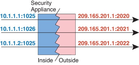
Dynamic PAT translates multiple real addresses to a single mapped IP address by translating the real address and source port to the mapped address and a unique port.

Each connection requires a separate translation session because the source port differs for each connection. For example, 10.1.1.1:1025 requires a separate translation from 10.1.1.1:1026.

The following figure shows a typical dynamic PAT scenario. Only real hosts can create a NAT session, and responding traffic is allowed back. The mapped address is the same for each translation, but the port is dynamically assigned.

Figure 4. Dynamic PAT

For the duration of the translation, a remote host on the destination network can initiate a connection to the translated host if an access rule allows it. Because the port address (both real and mapped) is unpredictable, a connection to the host is unlikely. Nevertheless, in this case you can rely on the security of the access rule.

After the connection expires, the port translation also expires. For multi-session PAT, the PAT timeout is used, 30 seconds by default. For per-session PAT, the xlate is immediately removed.


Note


We recommend that you use different PAT pools for each interface. If you use the same pool for multiple interfaces, especially if you use it for "any" interface, the pool can be quickly exhausted, with no ports available for new translations.


Dynamic PAT Disadvantages and Advantages

Dynamic PAT lets you use a single mapped address, thus conserving routable addresses. You can even use the ASA interface IP address as the PAT address.

You cannot use dynamic PAT for IPv6 (NAT66) when translating between interfaces in the same bridge group. This restriction does not apply when the interfaces are members of different bridge groups, or between a bridge group member and a standard routed interface.

Dynamic PAT does not work with some multimedia applications that have a data stream that is different from the control path.

Dynamic PAT might also create a large number of connections appearing to come from a single IP address, and servers might interpret the traffic as a DoS attack. You can configure a PAT pool of addresses and use a round-robin assignment of PAT addresses to mitigate this situation.

PAT Pool Object Guidelines

When creating network objects for a PAT pool, follow these guidelines.

For a PAT pool
  • Ports are mapped to an available port in the 1024 to 65535 range. You can optionally include the reserved ports, those below 1024, to make the entire port range available for translations.

    When operating in a cluster, blocks of 512 ports per address are allocated to the members of the cluster, and mappings are made within these port blocks. If you also enable block allocation, the ports are distributed according to the block allocation size, whose default is also 512.

  • If you enable block allocation for a PAT pool, port blocks are allocated in the 1024-65535 range only. Thus, if an application requires a low port number (1-1023), it might not work. For example, an application requesting port 22 (SSH) will get a mapped port within the range of 1024-65535 and within the block allocated to the host.

  • If you use the same PAT pool object in two separate rules, then be sure to specify the same options for each rule. For example, if one rule specifies extended PAT, then the other rule must also specify extended PAT.

  • If a host has an existing connection, then subsequent connections from that host use the same PAT IP address. If no ports are available, this can prevent the connection. Use the round robin option to avoid this problem.

  • For best performance, limit the number of IP addresses within a PAT pool to 10,000.

For extended PAT for a PAT pool
  • Many application inspections do not support extended PAT.

  • If you enable extended PAT for a dynamic PAT rule, then you cannot also use an address in the PAT pool as the PAT address in a separate static NAT with port translation rule. For example, if the PAT pool includes 10.1.1.1, then you cannot create a static NAT-with-port-translation rule using 10.1.1.1 as the PAT address.

  • If you use a PAT pool and specify an interface for fallback, you cannot specify extended PAT.

  • For VoIP deployments that use ICE or TURN, do not use extended PAT. ICE and TURN rely on the PAT binding to be the same for all destinations.

  • You cannot use extended PAT on units in a cluster.

  • Extended PAT increases memory usage on the device.

For round robin for a PAT pool
  • If a host has an existing connection, then subsequent connections from that host will use the same PAT IP address if ports are available. However, this “stickiness” does not survive a failover. If the device fails over, then subsequent connections from a host might not use the initial IP address.

  • IP address “stickiness” is also impacted if you mix PAT pool/round robin rules with interface PAT rules on the same interface. For any given interface, choose either a PAT pool or interface PAT; do not create competing PAT rules.

  • Round robin, especially when combined with extended PAT, can consume a large amount of memory. Because NAT pools are created for every mapped protocol/IP address/port range, round robin results in a large number of concurrent NAT pools, which use memory. Extended PAT results in an even larger number of concurrent NAT pools.

Configure Dynamic Network Object PAT

This section describes how to configure network object NAT for dynamic PAT.

Procedure


Step 1

(Optional.) Create a host or range network object (object network command), or a network object group (object-group network command), for the mapped addresses.

  • Instead of using an object, you can optionally configure an inline host address or specify the interface address.

  • If you use an object, the object or group cannot contain a subnet; the object must define a host, or for a PAT pool, a range; the group (for a PAT pool) can include hosts and ranges.

Step 2

Create or edit the network object for which you want to configure NAT: object network obj_name

Example:


hostname(config)# object network my-host-obj1

Step 3

(Skip when editing an object that has the right address.) Define the real IPv4 or IPv6 addresses that you want to translate.

  • host {IPv4_address | IPv6_address} —The IPv4 or IPv6 address of a single host. For example, 10.1.1.1 or 2001:DB8::0DB8:800:200C:417A.

  • subnet {IPv4_address IPv4_mask | IPv6_address/ IPv6_prefix} —The address of a network. For IPv4 subnets, include the mask after a space, for example, 10.0.0.0 255.0.0.0. For IPv6, include the address and prefix as a single unit (no spaces), such as 2001:DB8:0:CD30::/60.

  • range start_address end_address —A range of addresses. You can specify IPv4 or IPv6 ranges. Do not include masks or prefixes.

Example:


hostname(config-network-object)# range 10.1.1.1 10.1.1.90

Step 4

Configure dynamic PAT for the object IP addresses. You can only define a single NAT rule for a given object.

nat [(real_ifc,mapped_ifc)] dynamic {mapped_inline_host_ip | mapped_obj | pat-pool mapped-obj [round-robin] [extended] [include-reserve] [block-allocation] | interface [ipv6]} [interface [ipv6]]

Where:

  • Interfaces—(Required for bridge group member interfaces.) Specify the real (real_ifc) and mapped (mapped_ifc) interfaces. Be sure to include the parentheses. In routed mode, if you do not specify the real and mapped interfaces, all interfaces are used. You can also specify the keyword any for one or both of the interfaces, for example (any,outside), but any does not apply to bridge group member interfaces.

  • Mapped IP address—You can specify the mapped IP address as:

    • mapped_inline_host_ip —An inline host address.

    • mapped_obj —A network object that is defined as a host address.

    • pat-pool mapped-obj —A network object or group that contains multiple addresses.

    • interface [ipv6] —The IP address of the mapped interface is used as the mapped address. If you specify ipv6 , then the IPv6 address of the interface is used. For this option, you must configure a specific interface for the mapped_ifc . (You cannot specify interface when the mapped interface is a bridge group member.) You must use this keyword when you want to use the interface IP address; you cannot enter it inline or as an object.

  • For a PAT pool, you can specify one or more of the following options:

    • round-robin —Enables round-robin address allocation for a PAT pool. Without round robin, by default all ports for a PAT address will be allocated before the next PAT address is used. The round-robin method assigns an address/port from each PAT address in the pool before returning to use the first address again, and then the second address, and so on.

    • extended —Enables extended PAT. Extended PAT uses 65535 ports per service, as opposed to per IP address, by including the destination address and port in the translation information. Normally, the destination port and address are not considered when creating PAT translations, so you are limited to 65535 ports per PAT address. For example, with extended PAT, you can create a translation of 10.1.1.1:1027 when going to 192.168.1.7:23 as well as a translation of 10.1.1.1:1027 when going to 192.168.1.7:80.

    • include-reserve —Includes the reserved ports, 1-1023, in the range of ports that are available for address translation. If you do not specify this option, addresses are translated to ports in the 1024-65535 range only.

    • block-allocation —Enables port block allocation. For carrier-grade or large-scale PAT, you can allocate a block of ports for each host, rather than have NAT allocate one port translation at a time. If you allocate a block of ports, subsequent connections from the host use new randomly-selected ports within the block. If necessary, additional blocks are allocated if the host has active connections for all ports in the original block. Port blocks are allocated in the 1024-65535 range only. Port block allocation is compatible with round-robin , but you cannot use the extended option. You also cannot use interface PAT fallback.

  • Interface PAT fallback—(Optional.) The interface [ipv6] keyword enables interface PAT fallback when entered after a primary PAT address. After the primary PAT addresses are used up, then the IP address of the mapped interface is used. If you specify ipv6 , then the IPv6 address of the interface is used. For this option, you must configure a specific interface for the mapped_ifc . (You cannot specify interface when the mapped interface is a bridge group member.)

Example:


hostname(config-network-object)# nat (any,outside) dynamic interface


Examples

The following example configures dynamic PAT that hides the 192.168.2.0 network behind address 10.2.2.2:


hostname(config)# object network my-inside-net
hostname(config-network-object)# subnet 192.168.2.0 255.255.255.0
hostname(config-network-object)# nat (inside,outside) dynamic 10.2.2.2

The following example configures dynamic PAT that hides the 192.168.2.0 network behind the outside interface address:


hostname(config)# object network my-inside-net
hostname(config-network-object)# subnet 192.168.2.0 255.255.255.0
hostname(config-network-object)# nat (inside,outside) dynamic interface

The following example configures dynamic PAT with a PAT pool to translate the inside IPv6 network to an outside IPv4 network:


hostname(config)# object network IPv4_POOL
hostname(config-network-object)# range 203.0.113.1 203.0.113.254
hostname(config)# object network IPv6_INSIDE
hostname(config-network-object)# subnet 2001:DB8::/96
hostname(config-network-object)# nat (inside,outside) dynamic pat-pool IPv4_POOL

Configure Dynamic Twice PAT

This section describes how to configure twice NAT for dynamic PAT.

Procedure


Step 1

Create host or range network objects (object network command), or network object groups (object-group network command), for the source real addresses, the source mapped addresses, the destination real addresses, and the destination mapped addresses. You can also use an FQDN network object for the destination mapped address.

  • If you want to translate all source traffic, you can skip adding an object for the source real addresses, and instead specify the any keyword in the nat command.

  • If you want to use the interface address as the mapped address, you can skip adding an object for the source mapped addresses, and instead specify the interface keyword in the nat command.

  • If you want to configure destination static interface NAT with port translation only, you can skip adding an object for the destination mapped addresses, and instead specify the interface keyword in the nat command.

If you use an object, the object or group cannot contain a subnet. The object must define a host, or for a PAT pool, a range. The group (for a PAT pool) can include hosts and ranges.

Step 2

(Optional.) Create service objects for the destination real ports and the destination mapped ports.

For dynamic NAT, you can only perform port translation on the destination. A service object can contain both a source and destination port, but only the destination port is used in this case. If you specify the source port, it will be ignored.

Step 3

Configure dynamic PAT.

nat [(real_ifc,mapped_ifc)] [line | after-auto [line]] source dynamic {real-obj | any} {mapped_obj [interface [ipv6]] | pat-pool mapped-obj [round-robin] [extended] [include-reserve] [block-allocation] [interface [ipv6]] | interface [ipv6]} [destination static {mapped_obj | interface [ipv6]} real_obj] [service mapped_dest_svc_obj real_dest_svc_obj] [unidirectional] [inactive] [description description]

Where:

  • Interfaces—(Required for bridge group member interfaces.) Specify the real (real_ifc ) and mapped (mapped_ifc ) interfaces. Be sure to include the parentheses. In routed mode, if you do not specify the real and mapped interfaces, all interfaces are used. You can also specify the keyword any for one or both of the interfaces, for example (any,outside), but any does not apply to bridge group member interfaces..

  • Section and Line—(Optional.) By default, the NAT rule is added to the end of section 1 of the NAT table (see NAT Rule Order). If you want to add the rule into section 3 instead (after the network object NAT rules), then use the after-auto keyword. You can insert a rule anywhere in the applicable section using the line argument.

  • Source addresses:

    • Real—A network object, group, or the any keyword. Use the any keyword if you want to translate all traffic from the real interface to the mapped interface.

    • Mapped—Configure one of the following:

      • Network object—A network object that contains a host address.

      • pat-pool mapped-obj —A network object or group that contains multiple addresses.

      • interface [ipv6] —(Routed mode only.) The IP address of the mapped interface is used as the mapped address (interface PAT). If you specify ipv6 , then the IPv6 address of the interface is used. For this option, you must configure a specific interface for the mapped_ifc . (You cannot specify interface when the mapped interface is a bridge group member.) If you specify this keyword with a PAT pool or network object, you are enabling interface PAT fallback. After the PAT IP addresses are used up, then the IP address of the mapped interface is used.

      For a PAT pool, you can specify one or more of the following options:

      • round-robin —Enables round-robin address allocation for a PAT pool. Without round robin, by default all ports for a PAT address will be allocated before the next PAT address is used. The round-robin method assigns an address/port from each PAT address in the pool before returning to use the first address again, and then the second address, and so on.

      • extended —Enables extended PAT. Extended PAT uses 65535 ports per service, as opposed to per IP address, by including the destination address and port in the translation information. Normally, the destination port and address are not considered when creating PAT translations, so you are limited to 65535 ports per PAT address. For example, with extended PAT, you can create a translation of 10.1.1.1:1027 when going to 192.168.1.7:23 as well as a translation of 10.1.1.1:1027 when going to 192.168.1.7:80.

      • include-reserve —Includes the reserved ports, 1-1023, in the range of ports that are available for address translation. If you do not specify this option, addresses are translated to ports in the 1024-65535 range only.

      • block-allocation —Enables port block allocation. For carrier-grade or large-scale PAT, you can allocate a block of ports for each host, rather than have NAT allocate one port translation at a time. If you allocate a block of ports, subsequent connections from the host use new randomly-selected ports within the block. If necessary, additional blocks are allocated if the host has active connections for all ports in the original block. Port blocks are allocated in the 1024-65535 range only. Port block allocation is compatible with round-robin , but you cannot use the extended option. You also cannot use interface PAT fallback.

  • Destination addresses (Optional):

    • Mapped—Specify a network object or group, or for static interface NAT with port translation only (non-bridge group member interfaces only), specify the interface keyword. If you specify ipv6 , then the IPv6 address of the interface is used. If you specify interface , be sure to also configure the service keyword. For this option, you must configure a specific interface for the real_ifc . See Static NAT with Port Translation for more information.

    • Real—Specify a network object or group. For identity NAT, simply use the same object or group for both the real and mapped addresses.

  • Destination port—(Optional.) Specify the service keyword along with the mapped and real service objects. For identity port translation, simply use the same service object for both the real and mapped ports.

  • Unidirectional—(Optional.) Specify unidirectional so the destination addresses cannot initiate traffic to the source addresses.

  • Inactive—(Optional.) To make this rule inactive without having to remove the command, use the inactive keyword. To reactivate it, reenter the whole command without the inactive keyword.

  • Description—(Optional.) Provide a description up to 200 characters using the description keyword.

Example:


hostname(config)# nat (inside,outside) source dynamic MyInsNet interface
destination static Server1 Server1
description Interface PAT for inside addresses when going to server 1


Examples

The following example configures interface PAT for inside network 192.168.1.0/24 when accessing outside Telnet server 209.165.201.23, and Dynamic PAT using a PAT pool when accessing any server on the 203.0.113.0/24 network.


hostname(config)# object network INSIDE_NW
hostname(config-network-object)# subnet 192.168.1.0 255.255.255.0

hostname(config)# object network PAT_POOL
hostname(config-network-object)# range 209.165.200.225 209.165.200.254

hostname(config)# object network TELNET_SVR
hostname(config-network-object)# host 209.165.201.23

hostname(config)# object service TELNET
hostname(config-service-object)# service tcp destination eq 23

hostname(config)# object network SERVERS
hostname(config-network-object)# subnet 203.0.113.0 255.255.255.0

hostname(config)# nat (inside,outside) source dynamic INSIDE_NW interface 
destination static TELNET_SVR TELNET_SVR service TELNET TELNET
hostname(config)# nat (inside,outside) source dynamic INSIDE_NW pat-pool PAT_POOL
destination static SERVERS SERVERS

The following example configures interface PAT for inside network 192.168.1.0/24 when accessing outside IPv6 Telnet server 2001:DB8::23, and Dynamic PAT using a PAT pool when accessing any server on the 2001:DB8:AAAA::/96 network.


hostname(config)# object network INSIDE_NW
hostname(config-network-object)# subnet 192.168.1.0 255.255.255.0

hostname(config)# object network PAT_POOL
hostname(config-network-object)# range 2001:DB8:AAAA::1 2001:DB8:AAAA::200

hostname(config)# object network TELNET_SVR
hostname(config-network-object)# host 2001:DB8::23

hostname(config)# object service TELNET
hostname(config-service-object)# service tcp destination eq 23

hostname(config)# object network SERVERS
hostname(config-network-object)# subnet 2001:DB8:AAAA::/96

hostname(config)# nat (inside,outside) source dynamic INSIDE_NW interface ipv6 
destination static TELNET_SVR TELNET_SVR service TELNET TELNET
hostname(config)# nat (inside,outside) source dynamic INSIDE_NW pat-pool PAT_POOL
destination static SERVERS SERVERS

Configure PAT with Port Block Allocation

For carrier-grade or large-scale PAT, you can allocate a block of ports for each host, rather than have NAT allocate one port translation at a time (see RFC 6888). If you allocate a block of ports, subsequent connections from the host use new randomly-selected ports within the block. If necessary, additional blocks are allocated if the host has active connections for all ports in the original block. Blocks are freed when the last xlate that uses a port in the block is removed.

The main reason for allocating port blocks is reduced logging. The port block allocation is logged, connections are logged, but xlates created within the port block are not logged. On the other hand, this makes log analysis more difficult.

Port blocks are allocated in the 1024-65535 range only. Thus, if an application requires a low port number (1-1023), it might not work. For example, an application requesting port 22 (SSH) will get a mapped port within the range of 1024-65535 and within the block allocated to the host. You can create a separate NAT rule that does not use block allocation for applications that use low port numbers; for twice NAT, ensure the rule comes before the block allocation rule.

Before you begin

Usage notes for NAT rules:

  • You can include the round-robin keyword, but you cannot include extended , include-reserve , or interface (for interface PAT fallback). Other source/destination address and port information is also allowed.

  • As with all NAT changes, if you replace an existing rule, you must clear xlates related to the replaced rule to have the new rule take effect. You can clear them explicitly or simply wait for them to time out. When operating in a cluster, you must clear xlates globally across the cluster.


    Note


    If you are switching between a regular PAT and block allocation PAT rule, for object NAT, you must first delete the rule, then clear xlates. You can then create the new object NAT rule. Otherwise, you will see pat-port-block-state-mismatch drops in the show asp drop output.


  • For a given PAT pool, you must specify (or not specify) block allocation for all rules that use the pool. You cannot allocate blocks in one rule and not in another. PAT pools that overlap also cannot mix block allocation settings. You also cannot overlap static NAT with port translation rules with the pool.

Procedure


Step 1

(Optional.) Configure the block allocation size, which is the number of ports in each block.

xlate block-allocation size value

The range is 32-4096. The default is 512. Use the “no” form to return to the default.

If you do not use the default, ensure that the size you choose divides evenly into 64,512 (the number of ports in the 1024-65535 range). Otherwise, there will be ports that cannot be used. For example, if you specify 100, there will be 12 unused ports.

Step 2

(Optional.) Configure the maximum blocks that can be allocated per host.

xlate block-allocation maximum-per-host number

The limit is per protocol, so a limit of 4 means at most 4 UDP blocks, 4 TCP blocks, and 4 ICMP blocks per host. The range is 1-8, the default is 4. Use the “no” form to return to the default.

Step 3

(Optional.) Enable interim syslog generation.

xlate block-allocation pba-interim-logging seconds

By default, the system generates syslog messages during port block creation and deletion. If you enable interim logging, the system generates the following message at the interval you specify. The messages report all active port blocks allocated at that time, including the protocol (ICMP, TCP, UDP) and source and destination interface and IP address, and the port block. You can specify an interval from 21600-604800 seconds (6 hours to 7 days).

%ASA-6-305017: Pba-interim-logging: Active protocol block of ports for translation from real_interface:real_host_ip to mapped_interface:mapped_ip_address/start_port_num-end_port_num

Example:


ciscoasa(config)# xlate block-allocation pba-interim-logging 21600

Step 4

Add NAT rules that use PAT pool block allocation.

  • Object PAT.

    nat [(real_ifc,mapped_ifc)] dynamic pat-pool mapped-obj block-allocation

    Example:

    
    object network mapped-pat-pool
       range 10.100.10.1 10.100.10.2
    object network src_host
       host 10.111.10.15
    object network src_host
       nat (inside,outside) dynamic 
    pat-pool mapped-pat-pool block-allocation
    
    
  • Twice PAT.

    nat [(real_ifc,mapped_ifc)] [line | after-auto [line]] source dynamic real_obj pat-poolmapped-obj block-allocation

    Example:

    
    object network mapped-pat-pool
       range 10.100.10.1 10.100.10.2
    object network src_network
       subnet 10.100.10.0 255.255.255.0
    nat (inside,outside) 1 source dynamic src_network 
    pat-pool mapped-pat-pool block-allocation


Configure Per-Session PAT or Multi-Session PAT

By default, all TCP PAT traffic and all UDP DNS traffic uses per-session PAT. To use multi-session PAT for traffic, you can configure per-session PAT rules: a permit rule uses per-session PAT, and a deny rule uses multi-session PAT.

Per-session PAT improves the scalability of PAT and, for clustering, allows each member unit to own PAT connections; multi-session PAT connections have to be forwarded to and owned by the control unit. At the end of a per-session PAT session, the ASA sends a reset and immediately removes the xlate. This reset causes the end node to immediately release the connection, avoiding the TIME_WAIT state. Multi-session PAT, on the other hand, uses the PAT timeout, by default 30 seconds.

For “hit-and-run” traffic, such as HTTP or HTTPS, per-session PAT can dramatically increase the connection rate supported by one address. Without per-session PAT, the maximum connection rate for one address for an IP protocol is approximately 2000 per second. With per-session PAT, the connection rate for one address for an IP protocol is 65535/average-lifetime.

For traffic that can benefit from multi-session PAT, such as H.323, SIP, or Skinny, you can disable per-session PAT by creating a per-session deny rule. However, if you also want to use per-session PAT for the UDP ports used by these protocols, you must create the permit rules for them.

Before you begin

By default, the following rules are installed:


xlate per-session permit tcp any4 any4
xlate per-session permit tcp any4 any6
xlate per-session permit tcp any6 any4
xlate per-session permit tcp any6 any6
xlate per-session permit udp any4 any4 eq domain
xlate per-session permit udp any4 any6 eq domain
xlate per-session permit udp any6 any4 eq domain
xlate per-session permit udp any6 any6 eq domain

You cannot remove these rules, and they always exist after any manually-created rules. Because rules are evaluated in order, you can override the default rules. For example, to completely negate these rules, you could add the following:


xlate per-session deny tcp any4 any4
xlate per-session deny tcp any4 any6
xlate per-session deny tcp any6 any4
xlate per-session deny tcp any6 any6
xlate per-session deny udp any4 any4 eq domain
xlate per-session deny udp any4 any6 eq domain
xlate per-session deny udp any6 any4 eq domain
xlate per-session deny udp any6 any6 eq domain

Procedure


Create a permit or deny per-session PAT rule. This rule is placed above the default rules, but below any other manually-created rules. Be sure to create your rules in the order you want them applied.

xlate per-session {permit | deny} {tcpudp} source_ip [operator src_port] destination_ip [operator dest_port]

For the source and destination IP addresses, you can configure the following:

  • host ip_address—Specifies an IPv4 or IPv6 host address.

  • ip_address mask—Specifies an IPv4 network address and subnet mask.

  • ipv6-address/prefix-length—Specifies an IPv6 network address and prefix.

  • any4 and any6any4 specifies only IPv4 traffic; and any6 specifies any6 traffic.

The operator matches the port numbers used by the source or destination. The default is all ports. The permitted operators are:

  • lt—less than

  • gt—greater than

  • eq—equal to

  • neq—not equal to

  • range—an inclusive range of values. When you use this operator, specify two port numbers, for example, range 100 200.


Example

The following example creates a deny rule for H.323 traffic, so that it uses multi-session PAT:


hostname(config)# xlate per-session deny tcp any4 209.165.201.7 eq 1720
hostname(config)# xlate per-session deny udp any4 209.165.201.7 range 1718 1719

The following example enables the distribution of SIP across the members of a cluster by permitting per-session PAT for the SIP UDP port. Per-session PAT is the default for SIP TCP ports, so you do not need a rule for TCP unless you altered the default rules.


hostname(config)# xlate per-session permit udp any4 any4 eq sip

Static NAT

The following topics explain static NAT and how to implement it.

About Static NAT

Static NAT creates a fixed translation of a real address to a mapped address. Because the mapped address is the same for each consecutive connection, static NAT allows bidirectional connection initiation, both to and from the host (if an access rule exists that allows it). With dynamic NAT and PAT, on the other hand, each host uses a different address or port for each subsequent translation, so bidirectional initiation is not supported.

The following figure shows a typical static NAT scenario. The translation is always active so both real and remote hosts can initiate connections.

Figure 5. Static NAT

Note


You can disable bidirectionality if desired.


Static NAT with Port Translation

Static NAT with port translation lets you specify a real and mapped protocol and port.

When you specify the port with static NAT, you can choose to map the port and/or the IP address to the same value or to a different value.

The following figure shows a typical static NAT with port translation scenario showing both a port that is mapped to itself and a port that is mapped to a different value; the IP address is mapped to a different value in both cases. The translation is always active so both translated and remote hosts can initiate connections.

Figure 6. Typical Static NAT with Port Translation Scenario

Static NAT-with-port-translation rules limit access to the destination IP address for the specified port only. If you try to access the destination IP address on a different port not covered by a NAT rule, then the connection is blocked. In addition, for twice NAT, traffic that does not match the source IP address of the NAT rule will be dropped if it matches the destination IP address, regardless of the destination port. Therefore, you must add additional rules for all other traffic allowed to the destination IP address. For example, you can configure a static NAT rule for the IP address, without port specification, and place it after the port translation rule.


Note


For applications that require application inspection for secondary channels (for example, FTP and VoIP), NAT automatically translates the secondary ports.


Following are some other uses of static NAT with port translation.

Static NAT with Identity Port Translation

You can simplify external access to internal resources. For example, if you have three separate servers that provide services on different ports (such as FTP, HTTP, and SMTP), you can give external users a single IP address to access those services. You can then configure static NAT with identity port translation to map the single external IP address to the correct IP addresses of the real servers based on the port they are trying to access. You do not need to change the port, because the servers are using the standard ones (21, 80, and 25 respectively). For details on how to configure this example, see Single Address for FTP, HTTP, and SMTP (Static NAT-with-Port-Translation).

Static NAT with Port Translation for Non-Standard Ports

You can also use static NAT with port translation to translate a well-known port to a non-standard port or vice versa. For example, if inside web servers use port 8080, you can allow outside users to connect to port 80, and then undo translation to the original port 8080. Similarly, to provide extra security, you can tell web users to connect to non-standard port 6785, and then undo translation to port 80.

Static Interface NAT with Port Translation

You can configure static NAT to map a real address to an interface address/port combination. For example, if you want to redirect Telnet access for the device's outside interface to an inside host, then you can map the inside host IP address/port 23 to the outside interface address/port 23.

One-to-Many Static NAT

Typically, you configure static NAT with a one-to-one mapping. However, in some cases, you might want to configure a single real address to several mapped addresses (one-to-many). When you configure one-to-many static NAT, when the real host initiates traffic, it always uses the first mapped address. However, for traffic initiated to the host, you can initiate traffic to any of the mapped addresses, and they will be untranslated to the single real address.

The following figure shows a typical one-to-many static NAT scenario. Because initiation by the real host always uses the first mapped address, the translation of real host IP/first mapped IP is technically the only bidirectional translation.

Figure 7. One-to-Many Static NAT

For example, you have a load balancer at 10.1.2.27. Depending on the URL requested, it redirects traffic to the correct web server. For details on how to configure this example, see Inside Load Balancer with Multiple Mapped Addresses (Static NAT, One-to-Many).

Figure 8. One-to-Many Static NAT Example

Other Mapping Scenarios (Not Recommended)

NAT has the flexibility to allow any kind of static mapping scenario: one-to-one, one-to-many, but also few-to-many, many-to-few, and many-to-one mappings. We recommend using only one-to-one or one-to-many mappings. These other mapping options might result in unintended consequences.

Functionally, few-to-many is the same as one-to-many; but because the configuration is more complicated and the actual mappings may not be obvious at a glance, we recommend creating a one-to-many configuration for each real address that requires it. For example, for a few-to-many scenario, the few real addresses are mapped to the many mapped addresses in order (A to 1, B to 2, C to 3). When all real addresses are mapped, the next mapped address is mapped to the first real address, and so on until all mapped addresses are mapped (A to 4, B to 5, C to 6). This results in multiple mapped addresses for each real address. Just like a one-to-many configuration, only the first mappings are bidirectional; subsequent mappings allow traffic to be initiated to the real host, but all traffic from the real host uses only the first mapped address for the source.

The following figure shows a typical few-to-many static NAT scenario.

Figure 9. Few-to-Many Static NAT

For a many-to-few or many-to-one configuration, where you have more real addresses than mapped addresses, you run out of mapped addresses before you run out of real addresses. Only the mappings between the lowest real IP addresses and the mapped pool result in bidirectional initiation. The remaining higher real addresses can initiate traffic, but traffic cannot be initiated to them (returning traffic for a connection is directed to the correct real address because of the unique 5-tuple (source IP, destination IP, source port, destination port, protocol) for the connection).


Note


Many-to-few or many-to-one NAT is not PAT. If two real hosts use the same source port number and go to the same outside server and the same TCP destination port, and both hosts are translated to the same IP address, then both connections will be reset because of an address conflict (the 5-tuple is not unique).


The following figure shows a typical many-to-few static NAT scenario.

Figure 10. Many-to-Few Static NAT

Instead of using a static rule this way, we suggest that you create a one-to-one rule for the traffic that needs bidirectional initiation, and then create a dynamic rule for the rest of your addresses.

Configure Static Network Object NAT or Static NAT-with-Port-Translation

This section describes how to configure a static NAT rule using network object NAT.

Procedure


Step 1

(Optional.) Create a network object (object network command), or a network object group (object-group network command), for the mapped addresses.

  • Instead of using an object, you can configure an inline address or specify the interface address (for static NAT-with-port-translation).

  • If you use an object, the object or group can contain a host, range, or subnet.

Step 2

Create or edit the network object for which you want to configure NAT: object network obj_name

Example:


hostname(config)# object network my-host-obj1

Step 3

(Skip when editing an object that has the right address.) Define the real IPv4 or IPv6 addresses that you want to translate.

  • host {IPv4_address | IPv6_address}—The IPv4 or IPv6 address of a single host. For example, 10.1.1.1 or 2001:DB8::0DB8:800:200C:417A.

  • subnet {IPv4_address IPv4_mask | IPv6_address/IPv6_prefix}—The address of a network. For IPv4 subnets, include the mask after a space, for example, 10.0.0.0 255.0.0.0. For IPv6, include the address and prefix as a single unit (no spaces), such as 2001:DB8:0:CD30::/60.

  • range start_address end_address—A range of addresses. You can specify IPv4 or IPv6 ranges. Do not include masks or prefixes.

Example:


hostname(config-network-object)# subnet 10.2.1.0 255.255.255.0

Step 4

Configure static NAT for the object IP addresses. You can only define a single NAT rule for a given object.

nat [(real_ifc,mapped_ifc)] static {mapped_inline_host_ip | mapped_obj | interface [ipv6]} [net-to-net] [dns | service {tcp | udp | sctp} real_port mapped_port] [no-proxy-arp]

Where:

  • Interfaces—(Required for bridge group member interfaces.) Specify the real (real_ifc) and mapped (mapped_ifc) interfaces. Be sure to include the parentheses. In routed mode, if you do not specify the real and mapped interfaces, all interfaces are used. You can also specify the keyword any for one or both of the interfaces, for example (any,outside), but any does not apply to bridge group member interfaces..

  • Mapped IP address—You can specify the mapped IP address as one of the following. Typically, you configure the same number of mapped addresses as real addresses for a one-to-one mapping. You can, however, have a mismatched number of addresses. See Static NAT.

    • mapped_inline_host_ip —An inline host IP address. This provides a one-to-one mapping for host objects. For subnet objects, the same netmask is used for the inline host address, and you get one-to-one translations for addresses in the mapped inline host’s subnet. For range objects, the mapped address includes the same number of hosts that are in the range object, starting with the mapped host address. For example, if the real address is defined as a range from 10.1.1.1 through 10.1.1.6, and you specify 172.20.1.1 as the mapped address, then the mapped range will include 172.20.1.1 through 172.20.1.6. For NAT46 or NAT66 translations, this can be an IPv6 network address.

    • mapped_obj—An existing network object or group. To do a one-to-one mapping for a range of IP addresses, select an object that contains a range with the same number of addresses.

    • interface—(Static NAT-with-port-translation only.) The IP address of the mapped interface is used as the mapped address. If you specify ipv6, then the IPv6 address of the interface is used. For this option, you must configure a specific interface for the mapped_ifc. (You cannot specify interface when the mapped interface is a bridge group member.) You must use this keyword when you want to use the interface IP address; you cannot enter it inline or as an object. Be sure to also configure the service keyword.

  • Net-to-net—(Optional.) For NAT 46, specify net-to-net to translate the first IPv4 address to the first IPv6 address, the second to the second, and so on. Without this option, the IPv4-embedded method is used. For a one-to-one translation, you must use this keyword.

  • DNS—(Optional.) The dns keyword translates DNS replies. Be sure DNS inspection is enabled (it is enabled by default). See Rewriting DNS Queries and Responses Using NAT for more information.

  • Port translation—(Static NAT-with-port-translation only.) Specify service with the desired protocol keyword and the real and mapped ports. You can enter either a port number or a well-known port name (such as http).

  • No Proxy ARP—(Optional.) Specify no-proxy-arp to disable proxy ARP for incoming packets to the mapped IP addresses. For information on the conditions which might require the disabling of proxy ARP, see Mapped Addresses and Routing.

Example:


hostname(config-network-object)#
nat (inside,outside) static MAPPED_IPS service tcp 80 8080


Examples

The following example configures static NAT for the real host 10.1.1.1 on the inside to 10.2.2.2 on the outside with DNS rewrite enabled.


hostname(config)# object network my-host-obj1
hostname(config-network-object)# host 10.1.1.1
hostname(config-network-object)# nat (inside,outside) static 10.2.2.2 dns

The following example configures static NAT for the real host 10.1.1.1 on the inside to 10.2.2.2 on the outside using a mapped object.


hostname(config)# object network my-mapped-obj
hostname(config-network-object)# host 10.2.2.2

hostname(config-network-object)# object network my-host-obj1
hostname(config-network-object)# host 10.1.1.1
hostname(config-network-object)# nat (inside,outside) static my-mapped-obj

The following example configures static NAT-with-port-translation for 10.1.1.1 at TCP port 21 to the outside interface at port 2121.


hostname(config)# object network my-ftp-server
hostname(config-network-object)# host 10.1.1.1
hostname(config-network-object)# nat (inside,outside) static interface service tcp 21 2121

The following example maps an inside IPv4 network to an outside IPv6 network.


hostname(config)# object network inside_v4_v6
hostname(config-network-object)# subnet 10.1.1.0 255.255.255.0
hostname(config-network-object)# nat (inside,outside) static 2001:DB8::/96

The following example maps an inside IPv6 network to an outside IPv6 network.


hostname(config)# object network inside_v6
hostname(config-network-object)# subnet 2001:DB8:AAAA::/96
hostname(config-network-object)# nat (inside,outside) static 2001:DB8:BBBB::/96

Configure Static Twice NAT or Static NAT-with-Port-Translation

This section describes how to configure a static NAT rule using twice NAT.

Procedure


Step 1

Create host or range network objects (object network command), or network object groups (object-group network command), for the source real addresses, the source mapped addresses, the destination real addresses, and the destination mapped addresses. You can also use an FQDN network object for the destination mapped address.

  • If you want to configure source static interface NAT with port translation only, you can skip adding an object for the source mapped addresses, and instead specify the interface keyword in the nat command.

  • If you want to configure destination static interface NAT with port translation only, you can skip adding an object for the destination mapped addresses, and instead specify the interface keyword in the nat command.

If you do create objects, consider the following guidelines:

  • The mapped object or group can contain a host, range, or subnet.

  • The static mapping is typically one-to-one, so the real addresses have the same quantity as the mapped addresses. You can, however, have different quantities if desired. For more information, see Static NAT.

Step 2

(Optional.) Create service objects for the:

  • Source or Destination real ports

  • Source or Destination mapped ports

A service object can contain both a source and destination port; however, you should specify either the source or the destination port for both service objects. You should only specify both the source and destination ports if your application uses a fixed source port (such as some DNS servers); but fixed source ports are rare. For example, if you want to translate the port for the source host, then configure the source service.

Step 3

Configure static NAT.

nat [(real_ifc,mapped_ifc)] [line | {after-object [line]}] source static real_ob [mapped_objinterface [ipv6]] [destination static {mapped_obj | interface [ipv6]} real_obj] [service real_src_mapped_dest_svc_obj mapped_src_real_dest_svc_obj] [net-to-net] [dns] [unidirectional | no-proxy-arp] [inactive] [description desc]

Where:

  • Interfaces—(Required for bridge group member interfaces.) Specify the real (real_ifc) and mapped (mapped_ifc) interfaces. Be sure to include the parentheses. In routed mode, if you do not specify the real and mapped interfaces, all interfaces are used. You can also specify the keyword any for one or both of the interfaces, for example (any,outside), but any does not apply to bridge group member interfaces.

  • Section and Line—(Optional.) By default, the NAT rule is added to the end of section 1 of the NAT table (see NAT Rule Order). If you want to add the rule into section 3 instead (after the network object NAT rules), then use the after-auto keyword. You can insert a rule anywhere in the applicable section using the line argument.

  • Source addresses:

    • Real—Specify a network object or group. Do not use the any keyword, which would be used for identity NAT.

    • Mapped—Specify a different network object or group. For static interface NAT with port translation only, you can specify the interface keyword. If you specify ipv6, then the IPv6 address of the interface is used. If you specify interface, be sure to also configure the service keyword (in this case, the service objects should include only the source port). For this option, you must configure a specific interface for the mapped_ifc. (You cannot specify interface when the mapped interface is a bridge group member.) See Static NAT with Port Translation for more information.

  • Destination addresses (Optional):

    • Mapped—Specify a network object or group, or for static interface NAT with port translation only, specify the interface keyword. If you specify ipv6, then the IPv6 address of the interface is used. If you specify interface, be sure to also configure the service keyword (in this case, the service objects should include only the destination port). For this option, you must configure a specific interface for the real_ifc. (You cannot specify interface when the mapped interface is a bridge group member.)

    • Real—Specify a network object or group. For identity NAT, simply use the same object or group for both the real and mapped addresses.

  • Ports—(Optional.) Specify the service keyword along with the real and mapped service objects. For source port translation, the objects must specify the source service. The order of the service objects in the command for source port translation is service real_obj mapped_obj. For destination port translation, the objects must specify the destination service. The order of the service objects for destination port translation is service mapped_obj real_obj. In the rare case where you specify both the source and destination ports in the object, the first service object contains the real source port/mapped destination port; the second service object contains the mapped source port/real destination port. For identity port translation, simply use the same service object for both the real and mapped ports (source and/or destination ports, depending on your configuration).

  • Net-to-net—(Optional.) For NAT 46, specify net-to-net to translate the first IPv4 address to the first IPv6 address, the second to the second, and so on. Without this option, the IPv4-embedded method is used. For a one-to-one translation, you must use this keyword.

  • DNS—(Optional; for a source-only rule.) The dns keyword translates DNS replies. Be sure DNS inspection is enabled (it is enabled by default). You cannot configure the dns keyword if you configure a destination address. See Rewriting DNS Queries and Responses Using NAT for more information.

  • Unidirectional—(Optional.) Specify unidirectional so the destination addresses cannot initiate traffic to the source addresses.

  • No Proxy ARP—(Optional.) Specify no-proxy-arp to disable proxy ARP for incoming packets to the mapped IP addresses. See Mapped Addresses and Routing for more information.

  • Inactive—(Optional.) To make this rule inactive without having to remove the command, use the inactive keyword. To reactivate it, reenter the whole command without the inactive keyword.

  • Description—(Optional.) Provide a description up to 200 characters using the description keyword.

Example:


hostname(config)# nat (inside,dmz) source static MyInsNet MyInsNet_mapped
destination static Server1 Server1 service REAL_SRC_SVC MAPPED_SRC_SVC


Examples

The following example shows the use of static interface NAT with port translation. Hosts on the outside access an FTP server on the inside by connecting to the outside interface IP address with destination port 65000 through 65004. The traffic is untranslated to the internal FTP server at 192.168.10.100:6500 through 65004. Note that you specify the source port range in the service object (and not the destination port) because you want to translate the source address and port as identified in the command; the destination port is “any.” Because static NAT is bidirectional, “source” and “destination” refers primarily to the command keywords; the actual source and destination address and port in a packet depends on which host sent the packet. In this example, connections are originated from outside to inside, so the “source” address and port of the FTP server is actually the destination address and port in the originating packet.


hostname(config)# object service FTP_PASV_PORT_RANGE
hostname(config-service-object)# service tcp source range 65000 65004

hostname(config)# object network HOST_FTP_SERVER
hostname(config-network-object)# host 192.168.10.100

hostname(config)# nat (inside,outside) source static HOST_FTP_SERVER interface
service FTP_PASV_PORT_RANGE FTP_PASV_PORT_RANGE

The following example shows a static translation of one IPv6 network to another IPv6 when accessing an IPv6 network, and the dynamic PAT translation to an IPv4 PAT pool when accessing the IPv4 network:


hostname(config)# object network INSIDE_NW
hostname(config-network-object)# subnet 2001:DB8:AAAA::/96

hostname(config)# object network MAPPED_IPv6_NW
hostname(config-network-object)# subnet 2001:DB8:BBBB::/96

hostname(config)# object network OUTSIDE_IPv6_NW
hostname(config-network-object)# subnet 2001:DB8:CCCC::/96

hostname(config)# object network OUTSIDE_IPv4_NW
hostname(config-network-object)# subnet 10.1.1.0 255.255.255.0

hostname(config)# object network MAPPED_IPv4_POOL
hostname(config-network-object)# range 10.1.2.1 10.1.2.254

hostname(config)# nat (inside,outside) source static INSIDE_NW MAPPED_IPv6_NW
destination static OUTSIDE_IPv6_NW OUTSIDE_IPv6_NW
hostname(config)# nat (inside,outside) source dynamic INSIDE_NW pat-pool MAPPED_IPv4_POOL
destination static OUTSIDE_IPv4_NW OUTSIDE_IPv4_NW

Identity NAT

You might have a NAT configuration in which you need to translate an IP address to itself. For example, if you create a broad rule that applies NAT to every network, but want to exclude one network from NAT, you can create a static NAT rule to translate an address to itself. Identity NAT is necessary for remote access VPN, where you need to exempt the client traffic from NAT.

The following figure shows a typical identity NAT scenario.

Figure 11. Identity NAT

The following topics explain how to configure identity NAT.

Configure Identity Network Object NAT

This section describes how to configure an identity NAT rule using network object NAT.

Procedure


Step 1

(Optional.) Create a network object (object network command), or a network object group (object-group network command), for the mapped addresses.

  • Instead of using an object, you can configure an inline address.

  • If you use an object, the object must match the real addresses you want to translate.

Step 2

Create or edit the network object for which you want to configure NAT: object network obj_name

The object must be a different one than what you use for the mapped addresses, even though the contents must be the same in each object.

Example:


hostname(config)# object network my-host-obj1

Step 3

(Skip when editing an object that has the right address.) Define the real IPv4 or IPv6 addresses that you want to translate.

  • host {IPv4_address | IPv6_address}—The IPv4 or IPv6 address of a single host. For example, 10.1.1.1 or 2001:DB8::0DB8:800:200C:417A.

  • subnet {IPv4_address IPv4_mask | IPv6_address/IPv6_prefix}—The address of a network. For IPv4 subnets, include the mask after a space, for example, 10.0.0.0 255.0.0.0. For IPv6, include the address and prefix as a single unit (no spaces), such as 2001:DB8:0:CD30::/60.

  • range start_address end_address—A range of addresses. You can specify IPv4 or IPv6 ranges. Do not include masks or prefixes.

Example:


hostname(config-network-object)# subnet 10.2.1.0 255.255.255.0

Step 4

Configure identity NAT for the object IP addresses. You can only define a single NAT rule for a given object.

nat [(real_ifc,mapped_ifc)] static {mapped_inline_host_ip | mapped_obj} [no-proxy-arp] [route-lookup]

Where:

  • Interfaces—(Required for bridge group member interfaces.) Specify the real (real_ifc) and mapped (mapped_ifc) interfaces. Be sure to include the parentheses. In routed mode, if you do not specify the real and mapped interfaces, all interfaces are used. You can also specify the keyword any for one or both of the interfaces, for example (any,outside), but any does not apply to bridge group member interfaces.

  • Mapped IP addresses—Be sure to configure the same IP address for both the mapped and real address. Use one of the following:

    • mapped_inline_host_ip —An inline host IP address. For host objects, specify the same address. For range objects, specify the first address in the real range (the same number of addresses in the range will be used). For subnet objects, specify any address within the real subnet (all addresses in the subnet will be used).

    • mapped_obj—A network object or group that includes the same addresses as the real object.

  • No Proxy ARP—(Optional.) Specify no-proxy-arp to disable proxy ARP for incoming packets to the mapped IP addresses. For information on the conditions which might require the disabling of proxy ARP, see Mapped Addresses and Routing.

  • Route lookup—(Routed mode only; interfaces specified.) Specify route-lookup to determine the egress interface using a route lookup instead of using the interface specified in the NAT command. See Determining the Egress Interface for more information.

Example:


hostname(config-network-object)# nat (inside,outside) static MAPPED_IPS


Example

The following example maps a host address to itself using an inline mapped address:


hostname(config)# object network my-host-obj1
hostname(config-network-object)# host 10.1.1.1
hostname(config-network-object)# nat (inside,outside) static 10.1.1.1

The following example maps a host address to itself using a network object:


hostname(config)# object network my-host-obj1-identity
hostname(config-network-object)# host 10.1.1.1

hostname(config-network-object)# object network my-host-obj1
hostname(config-network-object)# host 10.1.1.1
hostname(config-network-object)# nat (inside,outside) static my-host-obj1-identity

Configure Identity Twice NAT

This section describes how to configure an identity NAT rule using twice NAT.

Procedure


Step 1

Create host or range network objects (object network command), or network object groups (object-group network command), for the source real addresses (you will typically use the same object for the source mapped addresses), the destination real addresses, and the destination mapped addresses. You can also use an FQDN network object for the destination mapped address.

  • If you want to perform identity NAT for all addresses, you can skip creating an object for the source real addresses and instead use the keywords any any in the nat command.

  • If you want to configure destination static interface NAT with port translation only, you can skip adding an object for the destination mapped addresses, and instead specify the interface keyword in the nat command.

If you do create objects, consider the following guidelines:

  • The mapped object or group can contain a host, range, or subnet.

  • The real and mapped source objects must match. You can use the same object for both, or you can create separate objects that contain the same IP addresses.

Step 2

(Optional.) Create service objects for the:

  • Source or Destination real ports

  • Source or Destination mapped ports

A service object can contain both a source and destination port; however, you should specify either the source or the destination port for both service objects. You should only specify both the source and destination ports if your application uses a fixed source port (such as some DNS servers); but fixed source ports are rare. For example, if you want to translate the port for the source host, then configure the source service.

Step 3

Configure identity NAT.

nat [(real_ifc,mapped_ifc)] [line | {after-object [line]}] source static {nw_obj nw_obj | any any} [destination static {mapped_obj | interface [ipv6]} real_obj] [service real_src_mapped_dest_svc_obj mapped_src_real_dest_svc_obj] [no-proxy-arp] [route-lookup] [inactive] [description desc]

Where:

  • Interfaces—(Required for bridge group member interfaces.) Specify the real (real_ifc) and mapped (mapped_ifc) interfaces. Be sure to include the parentheses. In routed mode, if you do not specify the real and mapped interfaces, all interfaces are used. You can also specify the keyword any for one or both of the interfaces, for example (any,outside), but any does not apply to bridge group member interfaces.

  • Section and Line—(Optional.) By default, the NAT rule is added to the end of section 1 of the NAT table (see NAT Rule Order). If you want to add the rule into section 3 instead (after the network object NAT rules), then use the after-auto keyword. You can insert a rule anywhere in the applicable section using the line argument.

  • Source addresses—Specify a network object, group, or the any keyword for both the real and mapped addresses.

  • Destination addresses (Optional):

    • Mapped—Specify a network object or group, or for static interface NAT with port translation only, specify the interface keyword. If you specify ipv6, then the IPv6 address of the interface is used. If you specify interface, be sure to also configure the service keyword (in this case, the service objects should include only the destination port). For this option, you must configure a specific interface for the real_ifc. (You cannot specify interface when the real interface is a bridge group member).

    • Real—Specify a network object or group. For identity NAT, simply use the same object or group for both the real and mapped addresses.

  • Ports—(Optional.) Specify the service keyword along with the real and mapped service objects. For source port translation, the objects must specify the source service. The order of the service objects in the command for source port translation is service real_obj mapped_obj. For destination port translation, the objects must specify the destination service. The order of the service objects for destination port translation is service mapped_obj real_obj. In the rare case where you specify both the source and destination ports in the object, the first service object contains the real source port/mapped destination port; the second service object contains the mapped source port/real destination port. For identity port translation, simply use the same service object for both the real and mapped ports (source and/or destination ports, depending on your configuration).

  • No Proxy ARP—(Optional.) Specify no-proxy-arp to disable proxy ARP for incoming packets to the mapped IP addresses. See Mapped Addresses and Routing for more information.

  • Route lookup—(Optional; routed mode only; interfaces specified.) Specify route-lookup to determine the egress interface using a route lookup instead of using the interface specified in the NAT command. See Determining the Egress Interface for more information.

  • Inactive—(Optional.) To make this rule inactive without having to remove the command, use the inactive keyword. To reactivate it, reenter the whole command without the inactive keyword.

  • Description—Optional.) Provide a description up to 200 characters using the description keyword.

Example:


hostname(config)# nat (inside,outside) source static MyInsNet MyInsNet
destination static Server1 Server1


Monitoring NAT

To monitor NAT, use the following commands:

  • show nat

    Shows NAT statistics, including hits for each NAT rule.

  • show nat pool

    Shows NAT pool statistics, including the addresses and ports allocated, and how many times they were allocated.

  • show running-config nat

    Shows the NAT configuration. You cannot see object NAT rules using show running-config object. When you use show running-config without modifiers, objects that include NAT rules are shown twice, first with the basic address configuration, then later in the configuration, the object with the NAT rule. The complete object, with the address and NAT rule, is not shown as a unit.

  • show xlate

    Shows current NAT session information.

History for NAT

Feature Name

Platform Releases

Description

Network Object NAT

8.3(1)

Configures NAT for a network object IP address(es).

We introduced or modified the following commands: nat (object network configuration mode), show nat, show xlate, show nat pool.

Twice NAT

8.3(1)

Twice NAT lets you identify both the source and destination address in a single rule.

We modified or introduced the following commands: nat, show nat, show xlate, show nat pool.

Identity NAT configurable proxy ARP and route lookup

8.4(2)/8.5(1)

In earlier releases for identity NAT, proxy ARP was disabled, and a route lookup was always used to determine the egress interface. You could not configure these settings. In 8.4(2) and later, the default behavior for identity NAT was changed to match the behavior of other static NAT configurations: proxy ARP is enabled, and the NAT configuration determines the egress interface (if specified) by default. You can leave these settings as is, or you can enable or disable them discretely. Note that you can now also disable proxy ARP for regular static NAT.

For pre-8.3 configurations, the migration of NAT exempt rules (the nat 0 access-list command) to 8.4(2) and later now includes the following keywords to disable proxy ARP and to use a route lookup: no-proxy-arp and route-lookup. The unidirectional keyword that was used for migrating to 8.3(2) and 8.4(1) is no longer used for migration. When upgrading to 8.4(2) from 8.3(1), 8.3(2), and 8.4(1), all identity NAT configurations will now include the no-proxy-arp and route-lookup keywords, to maintain existing functionality. The unidirectional keyword is removed.

We modified the following command: nat static [no-proxy-arp] [route-lookup].

PAT pool and round robin address assignment

8.4(2)/8.5(1)

You can now specify a pool of PAT addresses instead of a single address. You can also optionally enable round-robin assignment of PAT addresses instead of first using all ports on a PAT address before using the next address in the pool. These features help prevent a large number of connections from a single PAT address from appearing to be part of a DoS attack and makes configuration of large numbers of PAT addresses easy.

We modifed the following commands: nat dynamic [pat-pool mapped_object [round-robin]] and nat source dynamic [pat-pool mapped_object [round-robin]].

Round robin PAT pool allocation uses the same IP address for existing hosts

8.4(3)

When using a PAT pool with round robin allocation, if a host has an existing connection, then subsequent connections from that host will use the same PAT IP address if ports are available.

We did not modify any commands.

This feature is not available in 8.5(1) or 8.6(1).

Flat range of PAT ports for a PAT pool

8.4(3)

If available, the real source port number is used for the mapped port. However, if the real port is not available, by default the mapped ports are chosen from the same range of ports as the real port number: 0 to 511, 512 to 1023, and 1024 to 65535. Therefore, ports below 1024 have only a small PAT pool.

If you have a lot of traffic that uses the lower port ranges, when using a PAT pool, you can now specify a flat range of ports to be used instead of the three unequal-sized tiers: either 1024 to 65535, or 1 to 65535.

We modifed the following commands: nat dynamic [pat-pool mapped_object [flat [include-reserve]]] and nat source dynamic [pat-pool mapped_object [flat [include-reserve]]].

This feature is not available in 8.5(1) or 8.6(1).

Extended PAT for a PAT pool

8.4(3)

Each PAT IP address allows up to 65535 ports. If 65535 ports do not provide enough translations, you can now enable extended PAT for a PAT pool. Extended PAT uses 65535 ports per service, as opposed to per IP address, by including the destination address and port in the translation information.

We modifed the following command: nat dynamic [pat-pool mapped_object [extended]] and nat source dynamic [pat-pool mapped_object [extended]].

This feature is not available in 8.5(1) or 8.6(1).

Automatic NAT rules to translate a VPN peer’s local IP address back to the peer’s real IP address

8.4(3)

In rare situations, you might want to use a VPN peer’s real IP address on the inside network instead of an assigned local IP address. Normally with VPN, the peer is given an assigned local IP address to access the inside network. However, you might want to translate the local IP address back to the peer’s real public IP address if, for example, your inside servers and network security is based on the peer’s real IP address.

You can enable this feature on one interface per tunnel group. Object NAT rules are dynamically added and deleted when the VPN session is established or disconnected. You can view the rules using the show nat command.

Because of routing issues, we do not recommend using this feature unless you know you need it; contact Cisco TAC to confirm feature compatibility with your network. See the following limitations:

  • Only supports Cisco IPsec and Secure Client.

  • Return traffic to the public IP addresses must be routed back to the ASA so the NAT policy and VPN policy can be applied.

  • Does not support load-balancing (because of routing issues).

  • Does not support roaming (public IP changing).

We introduced the following command: nat-assigned-to-public-ip interface (tunnel-group general-attributes configuration mode).

NAT support for IPv6

9.0(1)

NAT now supports IPv6 traffic, as well as translating between IPv4 and IPv6. Translating between IPv4 and IPv6 is not supported in transparent mode.

We modified the following commands: nat (global and object network configuration modes), show nat, show nat pool, show xlate.

NAT support for reverse DNS lookups

9.0(1)

NAT now supports translation of the DNS PTR record for reverse DNS lookups when using IPv4 NAT, IPv6 NAT, and NAT64 with DNS inspection enabled for the NAT rule.

Per-session PAT

9.0(1)

The per-session PAT feature improves the scalability of PAT and, for clustering, allows each member unit to own PAT connections; multi-session PAT connections have to be forwarded to and owned by the control unit. At the end of a per-session PAT session, the ASA sends a reset and immediately removes the xlate. This reset causes the end node to immediately release the connection, avoiding the TIME_WAIT state. Multi-session PAT, on the other hand, uses the PAT timeout, by default 30 seconds. For “hit-and-run” traffic, such as HTTP or HTTPS, the per-session feature can dramatically increase the connection rate supported by one address. Without the per-session feature, the maximum connection rate for one address for an IP protocol is approximately 2000 per second. With the per-session feature, the connection rate for one address for an IP protocol is 65535/average-lifetime.

By default, all TCP traffic and UDP DNS traffic use a per-session PAT xlate. For traffic that requires multi-session PAT, such as H.323, SIP, or Skinny, you can disable per-session PAT by creating a per-session deny rule.

We introduced the following commands: xlate per-session, show nat pool.

Transactional Commit Model on NAT Rule Engine

9.3(1)

When enabled, a NAT rule update is applied after the rule compilation is completed; without affecting the rule matching performance.

We added the nat keyword to the following commands: asp rule-engine transactional-commit, show running-config asp rule-engine transactional-commit, clear configure asp rule-engine transactional-commit.

We added NAT to the following screen: Configuration > Device Management > Advanced > Rule Engine.

Carrier Grade NAT enhancements

9.5(1)

For carrier-grade or large-scale PAT, you can allocate a block of ports for each host, rather than have NAT allocate one port translation at a time (see RFC 6888).

We added the following commands: xlate block-allocation size , xlate block-allocation maximum-per-host . We added the block-allocation keyword to the nat command.

NAT support for SCTP

9.5(2)

You can now specify SCTP ports in static network object NAT rules. Using SCTP in static twice NAT is not recommended. Dynamic NAT/PAT does not support SCTP.

We modified the following commands: nat static (object).

Interim logging for NAT port block allocation.

9.12(1)

When you enable port block allocation for NAT, the system generates syslog messages during port block creation and deletion. If you enable interim logging, the system generates message 305017 at the interval you specify. The messages report all active port blocks allocated at that time, including the protocol (ICMP, TCP, UDP) and source and destination interface and IP address, and the port block.

We added the following command: xlate block-allocation pba-interim-logging seconds .

Changes to PAT address allocation in clustering. The PAT pool flat option is now enabled by default and it is not configurable.

9.15(1)

The way PAT addresses are distributed to the members of a cluster is changed. Previously, addresses were distributed to the members of the cluster, so your PAT pool would need a minimum of one address per cluster member. Now, the control unit instead divides each PAT pool address into equal-sized port blocks and distributes them across cluster members. Each member has port blocks for the same PAT addresses. Thus, you can reduce the size of the PAT pool, even to as few as one IP address, depending on the amount of connections you typically need to PAT. Port blocks are allocated in 512-port blocks from the 1024-65535 range. You can optionally included the reserved ports, 1-1023, in this block allocation when you configure PAT pool rules. For example, in a 4-node cluster, each node gets 32 blocks with which it will be able to handle 16384 connections per PAT pool IP address compared to a single node handling all 65535 connections per PAT pool IP address.

As part of this change, PAT pools for all systems, whether standalone or operating in a cluster, now use a flat port range of 1023 - 65535. Previously, you could optionally use a flat range by including the flat keyword in a PAT pool rule. The flat keyword is no longer supported: the PAT pool is now always flat. The include-reserve keyword, which was previously a sub-keyword to flat , is now an independent keyword within the PAT pool configuration. With this option, you can include the 1 - 1023 port range within the PAT pool.

Note that if you configure port block allocation (the block-allocation PAT pool option), your block allocation size is used rather than the default 512-port block. In addition, you cannot configure extended PAT for a PAT pool for systems in a cluster.

New/Modified commands: nat , show nat pool

New Section 0 for system-defined NAT rules.

9.16(1)

A new Section 0 has been added to the NAT rule table. This section is exclusively for the use of the system. Any NAT rules that the system needs for normal functioning are added to this section, and these rules take priority over any rules you create. Previously, system-defined rules were added to Section 1, and user-defined rules could interfere with proper system functioning. You cannot add, edit, or delete Section 0 rules, but you will see them in show nat detail command output.

Twice NAT support for fully-qualified domain name (FQDN) objects as the translated (mapped) destination.

9.17(1)

You can use an FQDN network object, such as one specifying www.example.com, as the translated (mapped) destination address in twice NAT rules. The system configures the rule based on the IP address returned from the DNS server.