NAT Examples and Reference

The following topics provide examples for configuring NAT, plus information on advanced configuration and troubleshooting.

Examples for Network Object NAT

Following are some configuration examples for network object NAT.

Providing Access to an Inside Web Server (Static NAT)

The following example performs static NAT for an inside web server. The real address is on a private network, so a public address is required. Static NAT is necessary so hosts can initiate traffic to the web server at a fixed address.

Figure 1. Static NAT for an Inside Web Server

Procedure


Step 1

Choose Configuration > Firewall > NAT.

Step 2

Choose Add > Network Object NAT Rule, name the new network object and define the web server host address.
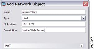
Step 3

Configure static NAT for the object.

Step 4

Click Advanced and configure the real and mapped interfaces.
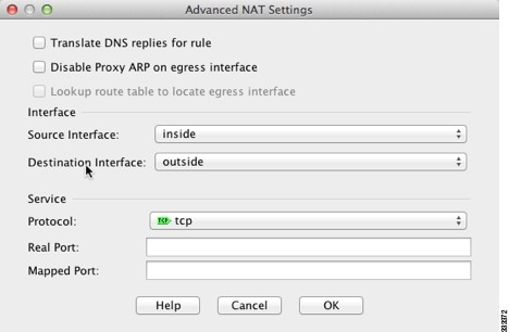
Step 5

Click OK to return to the Edit Network Object dialog box, click OK again, and then click Apply.


NAT for Inside Hosts (Dynamic NAT) and NAT for an Outside Web Server (Static NAT)

The following example configures dynamic NAT for inside users on a private network when they access the outside. Also, when inside users connect to an outside web server, that web server address is translated to an address that appears to be on the inside network.
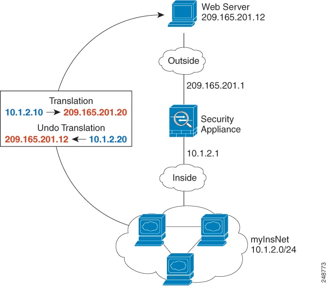
Figure 2. Dynamic NAT for Inside, Static NAT for Outside Web Server

Procedure


Step 1

Choose Configuration > Firewall > NAT.

Step 2

Choose Add > Network Object NAT Rule, name the new network object and define the inside network.

Step 3

Enable dynamic NAT for the inside network.
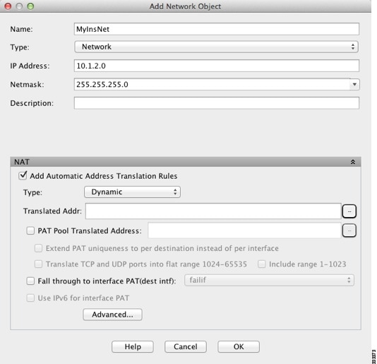
Step 4

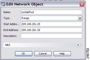
For the Translated Addr field, add a new network object for the dynamic NAT pool to which you want to translate the inside addresses by clicking the browse button.

  1. Choose Add > Network Object, name the new object, define the range of addresses in the NAT pool, and click OK.

  2. Choose the new network object by double-clicking it. Click OK to return to the NAT configuration.

Step 5

Click Advanced and configure the real and mapped interfaces.

Step 6

Click OK to return to the Edit Network Object dialog box, click then click OK again to return to the NAT Rules table.

Step 7

Choose Add > Network Object NAT Rule and create an object for the outside web server.
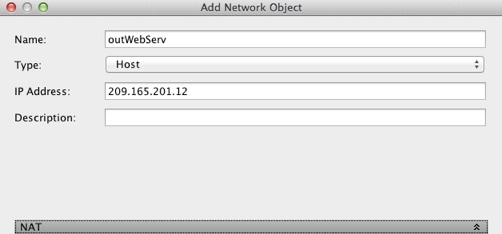
Step 8

Configure static NAT for the web server.

Step 9

Click Advanced and configure the real and mapped interfaces.

Step 10

Click OK to return to the Edit Network Object dialog box, click OK again, and then click Apply.


Inside Load Balancer with Multiple Mapped Addresses (Static NAT, One-to-Many)

The following example shows an inside load balancer that is translated to multiple IP addresses. When an outside host accesses one of the mapped IP addresses, it is untranslated to the single load balancer address. Depending on the URL requested, it redirects traffic to the correct web server.

Figure 3. Static NAT with One-to-Many for an Inside Load Balancer

Procedure


Step 1

Choose Configuration > Firewall > NAT.

Step 2

Choose Add > Network Object NAT Rule, name the new network object and define the load balancer address.

Step 3

Enable static NAT for the load balancer:

Step 4

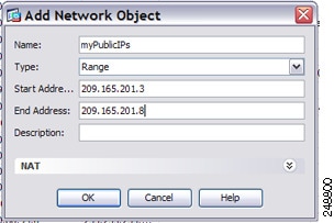
For the Translated Addr field, add a new network object for the static NAT group of addresses to which you want to translate the load balancer address by clicking the browse button.

  1. Choose Add > Network Object, name the new object, define the range of addresses, and click OK.

  2. Choose the new network object by double-clicking it. Click OK to return to the NAT configuration.

Step 5

Click Advanced and configure the real and mapped interfaces.

Step 6

Click OK to return to the Edit Network Object dialog box, click OK again, and then click Apply.


Single Address for FTP, HTTP, and SMTP (Static NAT-with-Port-Translation)

The following static NAT-with-port-translation example provides a single address for remote users to access FTP, HTTP, and SMTP. These servers are actually different devices on the real network, but for each server, you can specify static NAT-with-port-translation rules that use the same mapped IP address, but different ports.
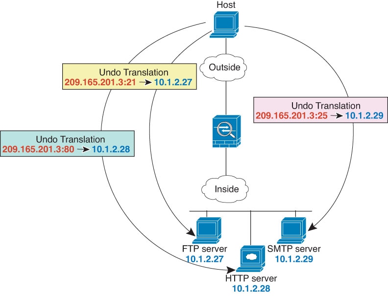
Figure 4. Static NAT-with-Port-Translation

Procedure


Step 1

Choose Configuration > Firewall > NAT.

Step 2

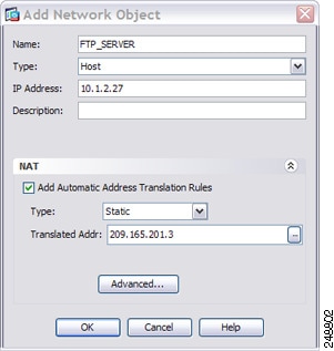
Configure the static network object NAT with port translation rule for the FTP server.

  1. Choose Add > Network Object NAT Rule.

  2. Name the new network object, define the FTP server address, enable static NAT, and enter the translated address.

  3. Click Advanced and configure the real and mapped interfaces and port translation for FTP, mapping the FTP port to itself.

  4. Click OK, then OK again to save the rule and return to the NAT page.

Step 3

Configure the static network object NAT with port translation rule for the HTTP server.

  1. Choose Add > Network Object NAT Rule.

  2. Name the new network object, define the HTTP server address, enable static NAT, and enter the translated address.

  3. Click Advanced and configure the real and mapped interfaces and port translation for HTTP, mapping the HTTP port to itself.

  4. Click OK, then OK again to save the rule and return to the NAT page.

Step 4

Configure the static network object NAT with port translation rule for the SMTP server.

  1. Choose Add > Network Object NAT Rule.

  2. Name the new network object, define the SMTP server address, enable static NAT, and enter the translated address.

  3. Click Advanced and configure the real and mapped interfaces and port translation for SMTP, mapping the SMTP port to itself.

  4. Click OK to return to the Edit Network Object dialog box, click OK again, and then click Apply.


Examples for Twice NAT

This section includes the following configuration examples:

Different Translation Depending on the Destination (Dynamic Twice PAT)

The following figure shows a host on the 10.1.2.0/24 network accessing two different servers. When the host accesses the server at 209.165.201.11, the real address is translated to 209.165.202.129:port. When the host accesses the server at 209.165.200.225, the real address is translated to 209.165.202.130:port.

Figure 5. Twice NAT with Different Destination Addresses

Procedure


Step 1

On the Configuration > Firewall > NAT Rules page, click Add > Add NAT Rule Before Network Object NAT Rules to add a NAT rule for traffic from the inside network to DMZ network 1.

If you want to add a NAT rule to section 3, after the network object NAT rules, choose Add NAT Rule After Network Object NAT Rules.

The Add NAT Rule dialog box appears.

Step 2

Set the source and destination interfaces.

Step 3

For the Original Source Address, click the browse button to add a new network object for the inside network in the Browse Original Source Address dialog box.

  1. Select Add > Network Object.

  2. Define the inside network addresses, and click OK.

  3. Choose the new network object by double-clicking it. Click OK to return to the NAT configuration.

Step 4

For the Original Destination Address, click the browse button to add a new network object for DMZ network 1 in the Browse Original Destination Address dialog box.

  1. Select Add > Network Object.

  2. Define the DMZ network 1 addresses, and click OK.

  3. Choose the new network object by double-clicking it. Click OK to return to the NAT configuration.

Step 5

Set the NAT Type to Dynamic PAT (Hide):

Step 6

For the Translated Source Address, click the browse button to add a new network object for the PAT address in the Browse Translated Source Address dialog box.

  1. Select Add > Network Object.

  2. Define the PAT address, and click OK.

  3. Choose the new network object by double-clicking it. Click OK to return to the NAT configuration.

Step 7

For the Translated Destination Address, type the name of the Original Destination Address (DMZnetwork1) or click the browse button to choose it.

Because you do not want to translate the destination address, you need to configure identity NAT for it by specifying the same address for the Original and Translated destination addresses.

Step 8

Click OK to add the rule to the NAT table.

Step 9

Click Add > Add NAT Rule Before Network Object NAT Rules or Add NAT Rule After Network Object NAT Rules to add a NAT rule for traffic from the inside network to DMZ network 2.

Step 10

Set the source and destination interfaces.

Step 11

For the Original Source Address, type the name of the inside network object (myInsideNetwork) or click the browse button to choose it.

Step 12

For the Original Destination Address, click the browse button to add a new network object for DMZ network 2 in the Browse Original Destination Address dialog box.

  1. Select Add > Network Object.

  2. Define the DMZ network 2 addresses, and click OK.

  3. Choose the new network object by double-clicking it. Click OK to return to the NAT configuration.

Step 13

Set the NAT Type to Dynamic PAT (Hide):

Step 14

For the Translated Source Address, click the browse button to add a new network object for the PAT address in the Browse Translated Source Address dialog box.

  1. Select Add > Network Object.

  2. Define the PAT address, and click OK.

  3. Choose the new network object by double-clicking it. Click OK to return to the NAT configuration.

Step 15

For the Translated Destination Address, type the name of the Original Destination Address (DMZnetwork2) or click the browse button to choose it.

Because you do not want to translate the destination address, you need to configure identity NAT for it by specifying the same address for the Original and Translated destination addresses.

Step 16

Click OK to add the rule to the NAT table.

Step 17

Click Apply.


Different Translation Depending on the Destination Address and Port (Dynamic PAT)

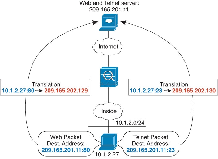
The following figure shows the use of source and destination ports. The host on the 10.1.2.0/24 network accesses a single host for both web services and Telnet services. When the host accesses the server for Telnet services, the real address is translated to 209.165.202.129:port. When the host accesses the same server for web services, the real address is translated to 209.165.202.130:port.

Figure 6. Twice NAT with Different Destination Ports

Procedure


Step 1

On the Configuration > Firewall > NAT Rules page, click Add > Add NAT Rule Before Network Object NAT Rules to add a NAT rule for traffic from the inside network to the Telnet server.

If you want to add a NAT rule to section 3, after the network object NAT rules, choose Add NAT Rule After Network Object NAT Rules.

The Add NAT Rule dialog box appears.

Step 2

Set the source and destination interfaces.

Step 3

For the Original Source Address, click the browse button to add a new network object for the inside network in the Browse Original Source Address dialog box.

  1. Select Add > Network Object.

  2. Define the inside network addresses, and click OK.

  3. Choose the new network object by double-clicking it. Click OK to return to the NAT configuration.

Step 4

For the Original Destination Address, click the browse button to add a new network object for the Telnet/Web server in the Browse Original Destination Address dialog box.

  1. Select Add > Network Object.

  2. Define the server address, and click OK.

  3. Choose the new network object by double-clicking it. Click OK to return to the NAT configuration.

Step 5

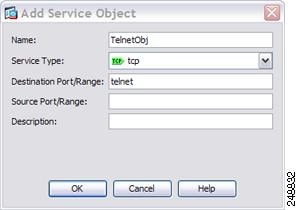
For the Original Service, click the browse button to add a new service object for Telnet in the Browse Original Service dialog box.

  1. Select Add > Service Object.

  2. Define the protocol and port, and click OK.

  3. Choose the new service object by double-clicking it. Click OK to return to the NAT configuration.

Step 6

Set the NAT Type to Dynamic PAT (Hide):

Step 7

For the Translated Source Address, click the browse button to add a new network object for the PAT address in the Browse Translated Source Address dialog box.

  1. Select Add > Network Object.

  2. Define the PAT address, and click OK.

  3. Choose the new network object by double-clicking it. Click OK to return to the NAT configuration.

Step 8

For the Translated Destination Address, type the name of the Original Destination Address (TelnetWebServer) or click the browse button to choose it.

Because you do not want to translate the destination address, you need to configure identity NAT for it by specifying the same address for the Original and Translated destination addresses.

Step 9

Click OK to add the rule to the NAT table.

Step 10

Click Add > Add NAT Rule Before Network Object NAT Rules or Add NAT Rule After Network Object NAT Rules to add a NAT rule for traffic from the inside network to the web server.

Step 11

Set the real and mapped interfaces.

Step 12

For the Original Source Address, type the name of the inside network object (myInsideNetwork) or click the browse button to choose it.

Step 13

For the Original Destination Address, type the name of the Telnet/web server network object (TelnetWebServer) or click the browse button to choose it.

Step 14

For the Original Service, click the browse button to add a new service object for HTTP in the Browse Original Service dialog box.

  1. Select Add > Service Object.

  2. Define the protocol and port, and click OK.

  3. Choose the new service object by double-clicking it. Click OK to return to the NAT configuration.

Step 15

Set the NAT Type to Dynamic PAT (Hide):

Step 16

For the Translated Source Address, click the browse button to add a new network object for the PAT address in the Browse Translated Source Address dialog box.

  1. Select Add > Network Object.

  2. Define the PAT address, and click OK.

  3. Choose the new network object by double-clicking it. Click OK to return to the NAT configuration.

Step 17

For the Translated Destination Address, type the name of the Original Destination Address (TelnetWebServer) or click the browse button to choose it.

Because you do not want to translate the destination address, you need to configure identity NAT for it by specifying the same address for the Original and Translated destination addresses.

Step 18

Click OK to add the rule to the NAT table.

Step 19

Click Apply.


NAT in Routed and Transparent Mode

You can configure NAT in both routed and transparent firewall mode. The following sections describe typical usage for each firewall mode.

NAT in Routed Mode

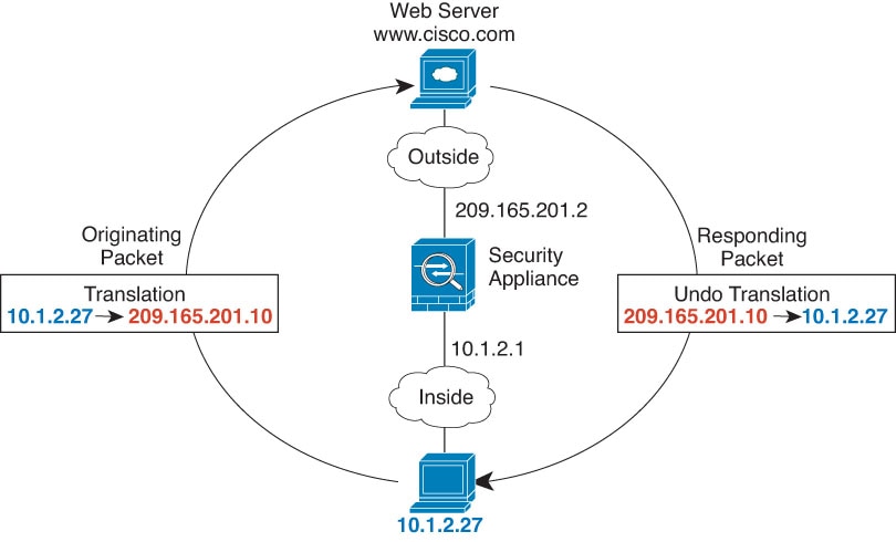
The following figure shows a typical NAT example in routed mode, with a private network on the inside.

Figure 7. NAT Example: Routed Mode
  1. When the inside host at 10.1.2.27 sends a packet to a web server, the real source address of the packet, 10.1.2.27, is translated to a mapped address, 209.165.201.10.

  2. When the server responds, it sends the response to the mapped address, 209.165.201.10, and the ASA receives the packet because the ASA performs proxy ARP to claim the packet.

  3. The ASA then changes the translation of the mapped address, 209.165.201.10, back to the real address, 10.1.2.27, before sending it to the host.

NAT in Transparent Mode

Using NAT in transparent mode eliminates the need for the upstream or downstream routers to perform NAT for their networks.

NAT in transparent mode has the following requirements and limitations:

  • You cannot configure interface PAT when the mapped address is a bridge group member interface, because there is no IP address attached to the interface.

  • ARP inspection is not supported. Moreover, if for some reason a host on one side of the ASA sends an ARP request to a host on the other side of the ASA, and the initiating host real address is mapped to a different address on the same subnet, then the real address remains visible in the ARP request.

  • Translating between IPv4 and IPv6 networks is not supported. Translating between two IPv6 networks, or between two IPv4 networks is supported.

The following figure shows a typical NAT scenario in transparent mode, with the same network on the inside and outside interfaces. The transparent firewall in this scenario is performing the NAT service so that the upstream router does not have to perform NAT.

Figure 8. NAT Example: Transparent Mode
  1. When the inside host at 10.1.1.75 sends a packet to a web server, the real source address of the packet, 10.1.1.75, is changed to a mapped address, 209.165.201.15.

  2. When the server responds, it sends the response to the mapped address, 209.165.201.15, and the ASA receives the packet because the upstream router includes this mapped network in a static route directed to the ASA management IP address.

  3. The ASA then undoes the translation of the mapped address, 209.165.201.15, back to the real address, 10.1.1.1.75. Because the real address is directly-connected, the ASA sends it directly to the host.

  4. For host 192.168.1.2, the same process occurs, except for returning traffic, the ASA looks up the route in its routing table and sends the packet to the downstream router at 10.1.1.3 based on the ASA static route for 192.168.1.0/24.

Routing NAT Packets

The ASA needs to be the destination for any packets sent to the mapped address. The ASA also needs to determine the egress interface for any packets it receives destined for mapped addresses. This section describes how the ASA handles accepting and delivering packets with NAT.

Mapped Addresses and Routing

When you translate the real address to a mapped address, the mapped address you choose determines how to configure routing, if necessary, for the mapped address.

See additional guidelines about mapped IP addresses in Additional Guidelines for NAT.

The following topics explain the mapped address types.

Addresses on the Same Network as the Mapped Interface

If you use addresses on the same network as the destination (mapped) interface, the ASA uses proxy ARP to answer any ARP requests for the mapped addresses, thus intercepting traffic destined for a mapped address. This solution simplifies routing because the ASA does not have to be the gateway for any additional networks. This solution is ideal if the outside network contains an adequate number of free addresses, a consideration if you are using a 1:1 translation like dynamic NAT or static NAT. Dynamic PAT greatly extends the number of translations you can use with a small number of addresses, so even if the available addresses on the outside network is small, this method can be used. For PAT, you can even use the IP address of the mapped interface.


Note

If you configure the mapped interface to be any interface, and you specify a mapped address on the same network as one of the mapped interfaces, then if an ARP request for that mapped address comes in on a different interface, then you need to manually configure an ARP entry for that network on the ingress interface, specifying its MAC address. Typically, if you specify any interface for the mapped interface, then you use a unique network for the mapped addresses, so this situation would not occur. Select Configuration > Device Management > Advanced > ARP > ARP Static Table to configure ARP.


Addresses on a Unique Network

If you need more addresses than are available on the destination (mapped) interface network, you can identify addresses on a different subnet. The upstream router needs a static route for the mapped addresses that points to the ASA.

Alternatively for routed mode, you can configure a static route on the ASA for the mapped addresses using any IP address on the destination network as the gateway, and then redistribute the route using your routing protocol. For example, if you use NAT for the inside network (10.1.1.0/24) and use the mapped IP address 209.165.201.5, then you can configure a static route for 209.165.201.5 255.255.255.255 (host address) to the 10.1.1.99 gateway that can be redistributed.


route inside 209.165.201.5 255.255.255.255 10.1.1.99

For transparent mode, if the real host is directly-connected, configure the static route on the upstream router to point to the ASA: in 8.3, specify the global management IP address; in 8.4(1) and later, specify the bridge group IP address. For remote hosts in transparent mode, in the static route on the upstream router, you can alternatively specify the downstream router IP address.

The Same Address as the Real Address (Identity NAT)

(8.3(1), 8.3(2), and 8.4(1)) The default behavior for identity NAT has proxy ARP disabled. You cannot configure this setting.

(8.4(2) and later) The default behavior for identity NAT has proxy ARP enabled, matching other static NAT rules. You can disable proxy ARP if desired. You can also disable proxy ARP for regular static NAT if desired, in which case you need to be sure to have proper routes on the upstream router.

Normally for identity NAT, proxy ARP is not required, and in some cases can cause connectivity issues. For example, if you configure a broad identity NAT rule for “any” IP address, then leaving proxy ARP enabled can cause problems for hosts on the network directly connected to the mapped interface. In this case, when a host on the mapped network wants to communicate with another host on the same network, then the address in the ARP request matches the NAT rule (which matches “any” address). The ASA will then proxy ARP for the address, even though the packet is not actually destined for the ASA. (Note that this problem occurs even if you have a twice NAT rule; although the NAT rule must match both the source and destination addresses, the proxy ARP decision is made only on the “source” address). If the ASA ARP response is received before the actual host ARP response, then traffic will be mistakenly sent to the ASA.

Figure 9. Proxy ARP Problems with Identity NAT

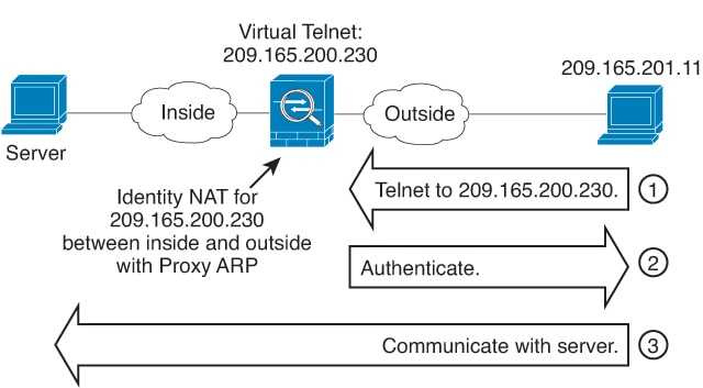
In rare cases, you need proxy ARP for identity NAT; for example for virtual Telnet. When using AAA for network access, a host needs to authenticate with the ASA using a service like Telnet before any other traffic can pass. You can configure a virtual Telnet server on the ASA to provide the necessary login. When accessing the virtual Telnet address from the outside, you must configure an identity NAT rule for the address specifically for the proxy ARP functionality. Due to internal processes for virtual Telnet, proxy ARP lets the ASA keep traffic destined for the virtual Telnet address rather than send the traffic out the source interface according to the NAT rule. (See the following figure).

Figure 10. Proxy ARP and Virtual Telnet

Transparent Mode Routing Requirements for Remote Networks

When you use NAT in transparent mode, some types of traffic require static routes. See the general operations configuration guide for more information.

Determining the Egress Interface

When you use NAT and the ASA receives traffic for a mapped address, then the ASA untranslates the destination address according to the NAT rule, and then it sends the packet on to the real address. The ASA determines the egress interface for the packet in the following ways:

  • Bridge group interfaces in Transparent mode—The ASA determines the egress interface for the real address by using the NAT rule; you must specify the source and destination bridge group member interfaces as part of the NAT rule.

  • Regular interfaces in Routed mode—The ASA determines the egress interface in one of the following ways:

    • You configure the interface in the NAT rule—The ASA uses the NAT rule to determine the egress interface. (8.3(1) through 8.4(1)) The only exception is for identity NAT, which always uses a route lookup, regardless of the NAT configuration. (8.4(2) and later) For identity NAT, the default behavior is to use the NAT configuration. However, you have the option to always use a route lookup instead. In certain scenarios, a route lookup override is required.

    • You do not configure the interface in the NAT rule—The ASA uses a route lookup to determine the egress interface.

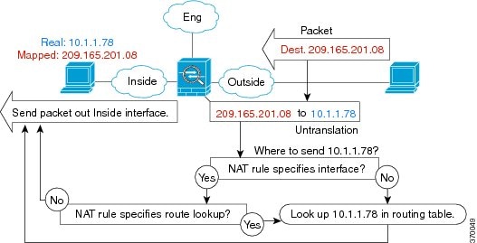
The following figure shows the egress interface selection method in routed mode. In almost all cases, a route lookup is equivalent to the NAT rule interface, but in some configurations, the two methods might differ.

Figure 11. Routed Mode Egress Interface Selection with NAT

NAT for VPN

The following topics explain NAT usage with the various types of VPN.

NAT and Remote Access VPN

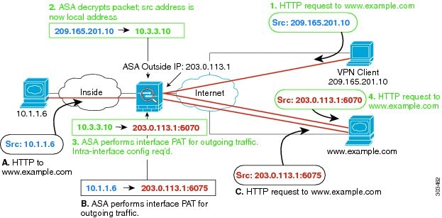
The following figure shows both an inside server (10.1.1.6) and a VPN client (209.165.201.10) accessing the Internet. Unless you configure split tunneling for the VPN client (where only specified traffic goes through the VPN tunnel), then Internet-bound VPN traffic must also go through the ASA. When the VPN traffic enters the ASA, the ASA decrypts the packet; the resulting packet includes the VPN client local address (10.3.3.10) as the source. For both inside and VPN client local networks, you need a public IP address provided by NAT to access the Internet. The below example uses interface PAT rules. To allow the VPN traffic to exit the same interface it entered, you also need to enable intra-interface communication (also known as “hairpin” networking).

Figure 12. Interface PAT for Internet-Bound VPN Traffic (Intra-Interface)

The following figure shows a VPN client that wants to access an inside mail server. Because the ASA expects traffic between the inside network and any outside network to match the interface PAT rule you set up for Internet access, traffic from the VPN client (10.3.3.10) to the SMTP server (10.1.1.6) will be dropped due to a reverse path failure: traffic from 10.3.3.10 to 10.1.1.6 does not match a NAT rule, but returning traffic from 10.1.1.6 to 10.3.3.10 should match the interface PAT rule for outgoing traffic. Because forward and reverse flows do not match, the ASA drops the packet when it is received. To avoid this failure, you need to exempt the inside-to-VPN client traffic from the interface PAT rule by using an identity NAT rule between those networks. Identity NAT simply translates an address to the same address.

Figure 13. Identity NAT for VPN Clients

See the following sample NAT configuration for the above network:


! Enable hairpin for non-split-tunneled VPN client traffic:
same-security-traffic permit intra-interface

! Identify local VPN network, & perform object interface PAT when going to Internet:
object network vpn_local
subnet 10.3.3.0 255.255.255.0
nat (outside,outside) dynamic interface

! Identify inside network, & perform object interface PAT when going to Internet:
object network inside_nw
subnet 10.1.1.0 255.255.255.0
nat (inside,outside) dynamic interface

! Use twice NAT to pass traffic between the inside network and the VPN client without
! address translation (identity NAT):
nat (inside,outside) source static inside_nw inside_nw destination static vpn_local vpn_local

NAT and Site-to-Site VPN

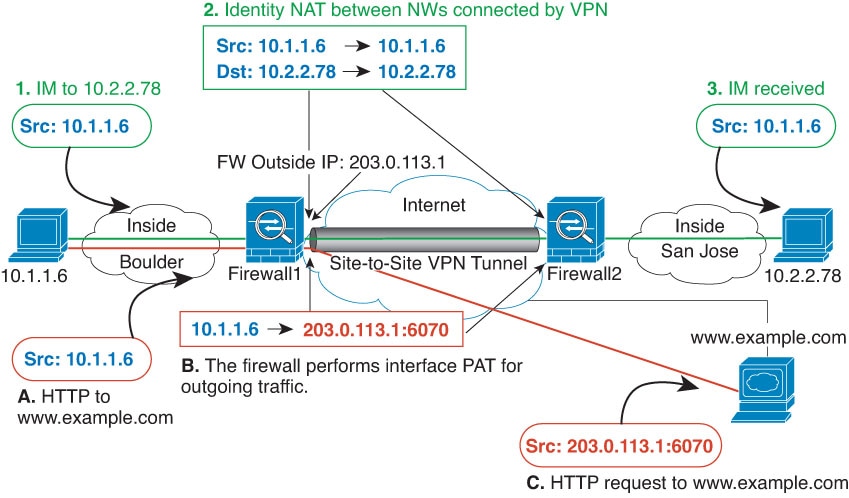
The following figure shows a site-to-site tunnel connecting the Boulder and San Jose offices. For traffic that you want to go to the Internet (for example from 10.1.1.6 in Boulder to www.example.com), you need a public IP address provided by NAT to access the Internet. The below example uses interface PAT rules. However, for traffic that you want to go over the VPN tunnel (for example from 10.1.1.6 in Boulder to 10.2.2.78 in San Jose), you do not want to perform NAT; you need to exempt that traffic by creating an identity NAT rule. Identity NAT simply translates an address to the same address.

Figure 14. Interface PAT and Identity NAT for Site-to-Site VPN

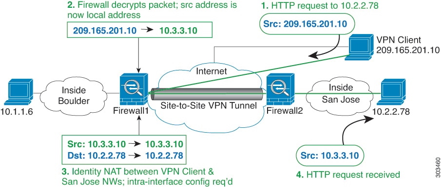
The following figure shows a VPN client connected to Firewall1 (Boulder), with a Telnet request for a server (10.2.2.78) accessible over a site-to-site tunnel between Firewall1 and Firewall2 (San Jose). Because this is a hairpin connection, you need to enable intra-interface communication, which is also required for non-split-tunneled Internet-bound traffic from the VPN client. You also need to configure identity NAT between the VPN client and the Boulder & San Jose networks, just as you would between any networks connected by VPN to exempt this traffic from outbound NAT rules.

Figure 15. VPN Client Access to Site-to-Site VPN

See the following sample NAT configuration for Firewall1 (Boulder) for the second example:


! Enable hairpin for VPN client traffic:
same-security-traffic permit intra-interface

! Identify local VPN network, & perform object interface PAT when going to Internet:
object network vpn_local
subnet 10.3.3.0 255.255.255.0
nat (outside,outside) dynamic interface

! Identify inside Boulder network, & perform object interface PAT when going to Internet:
object network boulder_inside
subnet 10.1.1.0 255.255.255.0
nat (inside,outside) dynamic interface

! Identify inside San Jose network for use in twice NAT rule:
object network sanjose_inside
subnet 10.2.2.0 255.255.255.0

! Use twice NAT to pass traffic between the Boulder network and the VPN client without
! address translation (identity NAT):
nat (inside,outside) source static boulder_inside boulder_inside 
destination static vpn_local vpn_local

! Use twice NAT to pass traffic between the Boulder network and San Jose without
! address translation (identity NAT):
nat (inside,outside) source static boulder_inside boulder_inside 
destination static sanjose_inside sanjose_inside

! Use twice NAT to pass traffic between the VPN client and San Jose without
! address translation (identity NAT):
nat (outside,outside) source static vpn_local vpn_local 
destination static sanjose_inside sanjose_inside

See the following sample NAT configuration for Firewall2 (San Jose):


! Identify inside San Jose network, & perform object interface PAT when going to Internet:
object network sanjose_inside
subnet 10.2.2.0 255.255.255.0
nat (inside,outside) dynamic interface

! Identify inside Boulder network for use in twice NAT rule:
object network boulder_inside
subnet 10.1.1.0 255.255.255.0

! Identify local VPN network for use in twice NAT rule:
object network vpn_local
subnet 10.3.3.0 255.255.255.0

! Use twice NAT to pass traffic between the San Jose network and Boulder without
! address translation (identity NAT):
nat (inside,outside) source static sanjose_inside sanjose_inside 
destination static boulder_inside boulder_inside

! Use twice NAT to pass traffic between the San Jose network and the VPN client without
! address translation (identity NAT):
nat (inside,outside) source static sanjose_inside sanjose_inside 
destination static vpn_local vpn_local

NAT and VPN Management Access

When using VPN, you can allow management access to an interface other than the one from which you entered the ASA. For example, if you enter the ASA from the outside interface, the management-access feature lets you connect to the inside interface using ASDM, SSH, Telnet, or SNMP; or you can ping the inside interface.

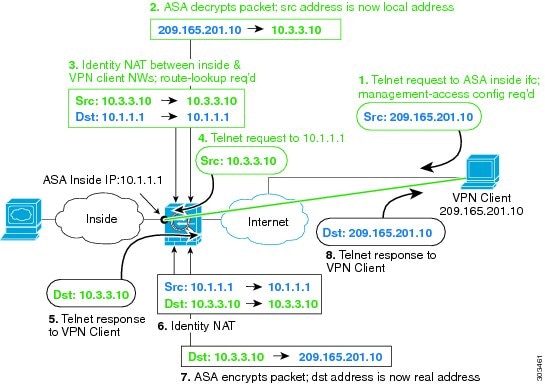
The following figure shows a VPN client Telnetting to the ASA inside interface. When you use a management-access interface, and you configure identity NAT according to NAT and Remote Access VPN or NAT and Site-to-Site VPN, you must configure NAT with the route lookup option. Without route lookup, the ASA sends traffic out the interface specified in the NAT command, regardless of what the routing table says; in the below example, the egress interface is the inside interface. You do not want the ASA to send the management traffic out to the inside network; it will never return to the inside interface IP address. The route lookup option lets the ASA send the traffic directly to the inside interface IP address instead of to the inside network. For traffic from the VPN client to a host on the inside network, the route lookup option will still result in the correct egress interface (inside), so normal traffic flow is not affected. See the Determining the Egress Interface for more information about the route lookup option.

Figure 16. VPN Management Access

See the following sample NAT configuration for the above network:


! Enable hairpin for non-split-tunneled VPN client traffic:
same-security-traffic permit intra-interface

! Enable management access on inside ifc:
management-access inside

! Identify local VPN network, & perform object interface PAT when going to Internet:
object network vpn_local
subnet 10.3.3.0 255.255.255.0
nat (outside,outside) dynamic interface

! Identify inside network, & perform object interface PAT when going to Internet:
object network inside_nw
subnet 10.1.1.0 255.255.255.0
nat (inside,outside) dynamic interface

! Use twice NAT to pass traffic between the inside network and the VPN client without
! address translation (identity NAT), w/route-lookup:
nat (outside,inside) source static vpn_local vpn_local 
destination static inside_nw inside_nw route-lookup

Troubleshooting NAT and VPN

See the following monitoring tools for troubleshooting NAT issues with VPN:

  • Packet tracer—When used correctly, a packet tracer shows which NAT rules a packet is hitting.

  • show nat detail—Shows hit counts and untranslated traffic for a given NAT rule.

  • show conn all—Lets you see active connections including to and from the box traffic.

To familiarize yourself with a non-working configuration vs. a working configuration, you can perform the following steps:

  1. Configure VPN without identity NAT.

  2. Enter show nat detail and show conn all.

  3. Add the identity NAT configuration.

  4. Repeat show nat detail and show conn all.

Translating IPv6 Networks

In cases where you need to pass traffic between IPv6-only and IPv4-only networks, you need to use NAT to convert between the address types. Even with two IPv6 networks, you might want to hide internal addresses from the outside network.

You can use the following translation types with IPv6 networks:

  • NAT64, NAT46—Translates IPv6 packets into IPv4 and vice versa. You need to define two policies, one for the IPv6 to IPv4 translation, and one for the IPv4 to IPv6 translation. Although you can accomplish this with a single twice NAT rule, if the DNS server is on the external network, you probably need to rewrite the DNS response. Because you cannot enable DNS rewrite on a twice NAT rule when you specify a destination, creating two network object NAT rules is the better solution.


    Note

    NAT46 supports static mappings only.


  • NAT66—Translates IPv6 packets to a different IPv6 address. We recommend using static NAT. Although you can use dynamic NAT or PAT, IPv6 addresses are in such large supply, you do not have to use dynamic NAT.


Note

NAT64 and NAT 46 are possible on standard routed interfaces only. NAT66 is possible on both routed and bridge group member interfaces.


NAT64/46: Translating IPv6 Addresses to IPv4

When traffic goes from an IPv6 network to an IPv4-only network, you need to convert the IPv6 address to IPv4, and return traffic from IPv4 to IPv6. You need to define two address pools, an IPv4 address pool to bind IPv6 addresses in the IPv4 network, and an IPv6 address pool to bind IPv4 addresses in the IPv6 network.

  • The IPv4 address pool for the NAT64 rule is normally small and typically might not have enough addresses to map one-to-one with the IPv6 client addresses. Dynamic PAT might more easily meet the possible large number of IPv6 client addresses compared to dynamic or static NAT.

  • The IPv6 address pool for the NAT46 rule can be equal to or larger than the number of IPv4 addresses to be mapped. This allows each IPv4 address to be mapped to a different IPv6 address. NAT46 supports static mappings only, so you cannot use dynamic PAT.

You need to define two policies, one for the source IPv6 network, and one for the destination IPv4 network. Although you can accomplish this with a single twice NAT rule, if the DNS server is on the external network, you probably need to rewrite the DNS response. Because you cannot enable DNS rewrite on a twice NAT rule when you specify a destination, creating two network object NAT rules is the better solution.

NAT64/46 Example: Inside IPv6 Network with Outside IPv4 Internet

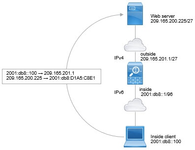
Following is a straight-forward example where you have an inside IPv6-only network, and you want to convert to IPv4 for traffic sent to the Internet. This example assumes you do not need DNS translation, so you can perform both the NAT64 and NAT46 translations in a single twice NAT rule.


Basic NAT64 network diagram.

In this example, you translate the inside IPv6 network to IPv4 using dynamic interface PAT with the IP address of the outside interface. Outside IPv4 traffic is statically translated to addresses on the 2001:db8::/96 network, allowing transmission on the inside network.

Procedure

Step 1

Create a network object for the inside IPv6 network.

  1. Choose Configuration > Firewall > Objects > Network Objects/Groups.

  2. Click Add > Network Object.

  3. Configure an object with the following properties:

    • Name—For example, inside_v6.

    • Type—Select Network.

    • IP Version—Select IPv6.

    • IP Address—Enter 2001:db8::

    • Prefix Length—Enter 96.

    Inside_v6 network object
  4. Click OK.

Step 2

Create the twice NAT rule to translate the IPv6 network to IPv4 and back again.

  1. Choose Configuration > Firewall > NAT Rules.

  2. Click Add > Add NAT Rule Before “Network Object” NAT Rules.

  3. Configure the following Match Criteria: Original Packet options:

    • Source Interface—Select inside.

    • Destination Interface—Select outside.

    • Source Address—Select the inside_v6 network object.

    • Destination Address—Select the inside_v6 network object.

    • Service—Keep the default, any.

  4. Configure the following Match Criteria: Translated Packet options:

    • Source NAT Type—Select Dynamic PAT (Hide).

    • Source Address—Select the outside interface.

    • Destination Address—Select any.

    Leave the rest of the options at their default values.

    The dialog box should look like the following:

    NAT 64 PAT rule
  5. Click OK.

    With this rule, any traffic from the 2001:db8::/96 subnet on the inside interface going to the outside interface gets a NAT64 PAT translation using the IPv4 address of the outside interface. Conversely, any IPv4 address on the outside network coming to the inside interface is translated to an address on the 2001:db8::/96 network using the embedded IPv4 address method.


NAT64/46 Example: Inside IPv6 Network with Outside IPv4 Internet and DNS Translation

Following is a typical example where you have an inside IPv6-only network, but there are some IPv4-only services on the outside Internet that internal users need.


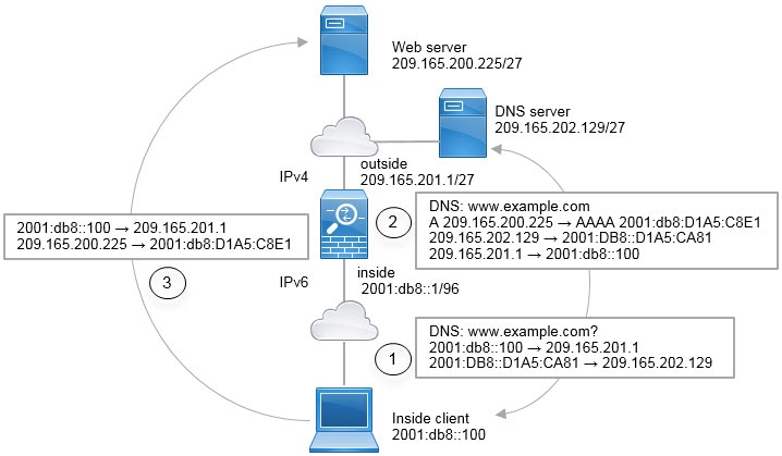
NAT64 network diagram.

In this example, you translate the inside IPv6 network to IPv4 using dynamic interface PAT with the IP address of the outside interface. Outside IPv4 traffic is statically translated to addresses on the 2001:db8::/96 network, allowing transmission on the inside network. You enable DNS rewrite on the NAT46 rule, so that replies from the external DNS server can be converted from A (IPv4) to AAAA (IPv6) records, and the addresses converted from IPv4 to IPv6.

Following is a typical sequence for a web request where a client at 2001:DB8::100 on the internal IPv6 network tries to open www.example.com.

  1. The client’s computer sends a DNS request to the DNS server at 2001:DB8::D1A5:CA81. The NAT rules make the following translations to the source and destination in the DNS request:

    • 2001:DB8::100 to a unique port on 209.165.201.1 (The NAT64 interface PAT rule.)

    • 2001:DB8::D1A5:CA81 to 209.165.202.129 (The NAT46 rule. D1A5:CA81 is the IPv6 equivalent of 209.165.202.129.)

  2. The DNS server responds with an A record indicating that www.example.com is at 209.165.200.225. The NAT46 rule, with DNS rewrite enabled, converts the A record to the IPv6-equivalent AAAA record, and translates 209.165.200.225 to 2001:db8:D1A5:C8E1in the AAAA record. In addition, the source and destination addresses in the DNS response are untranslated:

    • 209.165.202.129 to 2001:DB8::D1A5:CA81

    • 209.165.201.1 to 2001:db8::100

  3. The IPv6 client now has the IP address of the web server, and makes an HTTP request to www.example.com at 2001:db8:D1A5:C8E1. (D1A5:C8E1 is the IPv6 equivalent of 209.165.200.225.) The source and destination of the HTTP request are translated:

    • 2001:DB8::100 to a unique port on 209.156.101.54 (The NAT64 interface PAT rule.)

    • 2001:db8:D1A5:C8E1 to 209.165.200.225 (The NAT46 rule.)

The following procedure explains how to configure this example.

Procedure

Step 1

Choose Configuration > Firewall > NAT Rules.

Step 2

Configure the NAT64 dynamic PAT rule for the inside IPv6 network.

  1. Choose Add > Network Object NAT Rule.

  2. Configure the basic object properties:

    • Name—For example, inside_v6.

    • Type—Select Network.

    • IP Version—Select IPv6.

    • IP Address—Enter 2001:db8::.

    • Prefix Length—Enter 96.

  3. Select Dynamic or Dynamic PAT (Hide) for NAT Type.

  4. For the Translated Address, click the browse button and select the “outside” interface.


    NAT64 inside_v6 object NAT.

  5. Click the Advanced button and configure the following options:

    • Source Interface—Select “inside.”

    • Destination Interface—The “outside” interface should already be selected.

  6. Click OK to save the advanced settings.

  7. Click OK to add the NAT rule.

    With this rule, any traffic from the 2001:db8::/96 subnet on the inside interface going to the outside interface gets a NAT64 PAT translation using the IPv4 address of the outside interface.

Step 3

Configure the static NAT46 rule for the outside IPv4 network.

  1. Choose Add > Network Object NAT Rule.

  2. Configure the basic object properties:

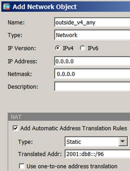
    • Name—For example, outside_v4_any.

    • Type—Select Network.

    • IP Version—Select IPv4.

    • IP Address—Enter 0.0.0.0.

    • Netmask—Enter 0.0.0.0.

  3. Configure the NAT properties:

    • NAT Type—Select Static.

    • Translated Address—Enter 2001:db8::/96.


    NAT46 static translation rule.

  4. Click the Advanced button and configure the following options:

    • Translate DNS Replies for Rule—Select this option.

    • Source Interface—Select “outside.”

    • Destination Interface—Select “inside.”


    NAT46 rule advanced options with DNS rewrite enabled.

  5. Click OK to save the advanced settings.

  6. Click OK to add the NAT rule.

    With this rule, any IPv4 address on the outside network coming to the inside interface is translated to an address on the 2001:db8::/96 network using the embedded IPv4 address method. In addition, DNS responses are converted from A (IPv4) to AAAA (IPv6) records, and the addresses converted from IPv4 to IPv6.


NAT66: Translating IPv6 Addresses to Different IPv6 Addresses

When going from an IPv6 network to another IPv6 network, you can translate the addresses to different IPv6 addresses on the outside network. We recommend using static NAT. Although you can use dynamic NAT or PAT, IPv6 addresses are in such large supply, you do not have to use dynamic NAT.

Because you are not translating between different address types, you need a single rule for NAT66 translations. You can easily model these rules using network object NAT. However, if you do not want to allow returning traffic, you can make the static NAT rule unidirectional using twice NAT only.

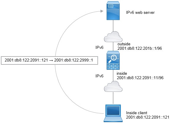
NAT66 Example, Static Translation between Networks

You can configure a static translation between IPv6 address pools using network object NAT. The following example explains how to convert inside addresses on the 2001:db8:122:2091::/96 network to outside addresses on the 2001:db8:122:2999::/96 network.


NAT66 static translation network diagram.

Procedure

Step 1

Choose Configuration > Firewall > NAT Rules.

Step 2

Configure the static NAT rule for the inside IPv6 network.

  1. Choose Add > Network Object NAT Rule.

  2. Configure the basic object properties:

    • Name—For example, inside_v6.

    • Type—Select Network.

    • IP Version—Select IPv6.

    • IP Address—Enter 2001:db8:122:2091::.

    • Prefix Length—Enter 96.

  3. Select Static for NAT Type.

  4. For the Translated Address, enter 2001:db8:122:2999::/96.


    NAT66 static rule.

  5. Click the Advanced button and configure the following options:

    • Source Interface—Select “inside.”

    • Destination Interface—Select “outside.”

  6. Click OK to save the advanced settings.

  7. Click OK to add the NAT rule.

    With this rule, any traffic from the 2001:db8:122:2091::/96 subnet on the inside interface going to the outside interface gets a static NAT66 translation to an address on the 2001:db8:122:2999::/96 network.


NAT66 Example, Simple IPv6 Interface PAT

A simple approach for implementing NAT66 is to dynamically assign internal addresses to different ports on the outside interface IPv6 address.

When you configure an interface PAT rule for NAT66, all the global addresses that are configured on that interface are used for PAT mapping. Link-local or site-local addresses for the interface are not used for PAT.


NAT66 interface PAT network diagram.

Procedure

Step 1

Choose Configuration > Firewall > NAT Rules.

Step 2

Configure the dynamic PAT rule for the inside IPv6 network.

  1. Choose Add > Network Object NAT Rule.

  2. Configure the basic object properties:

    • Name—For example, inside_v6.

    • Type—Select Network.

    • IP Version—Select IPv6.

    • IP Address—Enter 2001:db8:122:2091::.

    • Prefix Length—Enter 96.

  3. Select Dynamic or Dynamic PAT (Hide) for NAT Type.

  4. For the Translated Address, click the browse button and select the “outside” interface.

  5. Select the Use IPv6 for Interface PAT option.


    NAT66 interface PAT rule.

  6. Click the Advanced button and configure the following options:

    • Source Interface—Select “inside.”

    • Destination Interface—The “outside” interface should already be selected.

  7. Click OK to save the advanced settings.

  8. Click OK to add the NAT rule.

    With this rule, any traffic from the 2001:db8:122:2091::/96 subnet on the inside interface going to the outside interface gets a NAT66 PAT translation to one of the IPv6 global addresses configured for the outside interface.


Rewriting DNS Queries and Responses Using NAT

You might need to configure the ASA to modify DNS replies by replacing the address in the reply with an address that matches the NAT configuration. You can configure DNS modification when you configure each translation rule. DNS modification is also known as DNS doctoring.

This feature rewrites the address in DNS queries and replies that match a NAT rule (for example, the A record for IPv4, the AAAA record for IPv6, or the PTR record for reverse DNS queries). For DNS replies traversing from a mapped interface to any other interface, the record is rewritten from the mapped value to the real value. Inversely, for DNS replies traversing from any interface to a mapped interface, the record is rewritten from the real value to the mapped value. This feature works with NAT44,NAT 66, NAT46, and NAT64.

Following are the main circumstances when you would need to configure DNS rewrite on a NAT rule.

  • The rule is NAT64 or NAT46, and the DNS server is on the outside network. You need DNS rewrite to convert between DNS A records (for IPv4) and AAAA records (for IPv6).

  • The DNS server is on the outside, clients are on the inside, and some of the fully-qualified domain names that the clients use resolve to other inside hosts.

  • The DNS server is on the inside and responds with private IP addresses, clients are on the outside, and the clients access fully-qualified domain names that point to servers that are hosted on the inside.

DNS Rewrite Limitations

Following are some limitations with DNS rewrite:

  • DNS rewrite is not applicable for PAT because multiple PAT rules are applicable for each A or AAAA record, and the PAT rule to use is ambiguous.

  • If you configure a twice NAT rule, you cannot configure DNS modification if you specify the destination address as well as the source address. These kinds of rules can potentially have a different translation for a single address when going to A vs. B. Therefore, the can not accurately match the IP address inside the DNS reply to the correct twice NAT rule; the DNS reply does not contain information about which source/destination address combination was in the packet that prompted the DNS request.

  • You must enable DNS application inspection with DNS NAT rewrite enabled for NAT rules to rewrite DNS queries and responses. By default, DNS inspection with DNS NAT rewrite enabled is globally applied, so you probably do not need to change the inspection configuration.

  • DNS rewrite is actually done on the xlate entry, not the NAT rule. Thus, if there is no xlate for a dynamic rule, rewrite cannot be done correctly. The same problem does not occur for static NAT.

  • DNS rewrite does not rewrite DNS Dynamic Update messages (opcode 5).

The following topics provide examples of DNS rewrite in NAT rules.

DNS Reply Modification, DNS Server on Outside

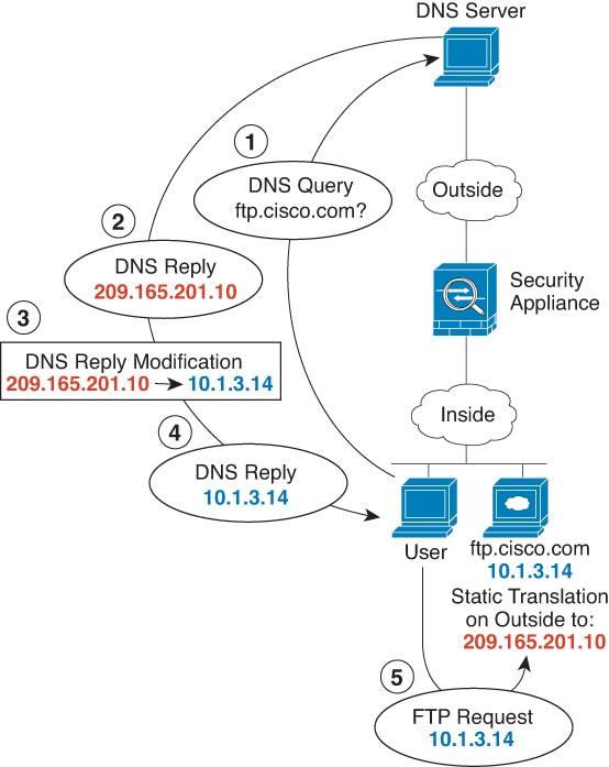
The following figure shows a DNS server that is accessible from the outside interface. A server, ftp.cisco.com, is on the inside interface. You configure NAT to statically translate the ftp.cisco.com real address (10.1.3.14) to a mapped address (209.165.201.10) that is visible on the outside network.

In this case, you want to enable DNS reply modification on this static rule so that inside users who have access to ftp.cisco.com using the real address receive the real address from the DNS server, and not the mapped address.

When an inside host sends a DNS request for the address of ftp.cisco.com, the DNS server replies with the mapped address (209.165.201.10). The system refers to the static rule for the inside server and translates the address inside the DNS reply to 10.1.3.14. If you do not enable DNS reply modification, then the inside host attempts to send traffic to 209.165.201.10 instead of accessing ftp.cisco.com directly.

Procedure


Step 1

Choose Configuration > Firewall > NAT.

Step 2

Choose Add > Network Object NAT Rule.

Step 3

Name the new network object, define the FTP server address, enable static NAT and enter the translated address.

Step 4

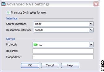
Click Advanced and configure the real and mapped interfaces and DNS modification.

Step 5

Click OK to return to the Edit Network Object dialog box, click OK again, and then click Apply.


DNS Reply Modification, DNS Server, Host, and Server on Separate Networks

The following figure shows a user on the inside network requesting the IP address for ftp.cisco.com, which is on the DMZ network, from an outside DNS server. The DNS server replies with the mapped address (209.165.201.10) according to the static rule between outside and DMZ even though the user is not on the DMZ network. The ASA translates the address inside the DNS reply to 10.1.3.14.

If the user needs to access ftp.cisco.com using the real address, then no further configuration is required. If there is also a static rule between the inside and DMZ, then you also need to enable DNS reply modification on this rule. The DNS reply will then be modified two times.In this case, the ASA again translates the address inside the DNS reply to 192.168.1.10 according to the static rule between inside and DMZ.

Figure 17. DNS Reply Modification, DNS Server, Host, and Server on Separate Networks

DNS Reply Modification, DNS Server on Host Network

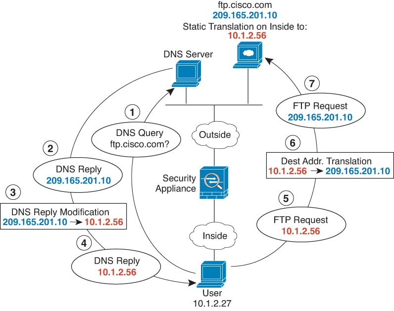
The following figure shows an FTP server and DNS server on the outside. The system has a static translation for the outside server. In this case, when an inside user requests the address for ftp.cisco.com from the DNS server, the DNS server responds with the real address, 209.165.20.10. Because you want inside users to use the mapped address for ftp.cisco.com (10.1.2.56) you need to configure DNS reply modification for the static translation.

Procedure


Step 1

Choose Configuration > Firewall > NAT.

Step 2

Choose Add > Network Object NAT Rule.

Step 3

Name the new network object, define the FTP server address, enable static NAT and enter the translated address.

Step 4

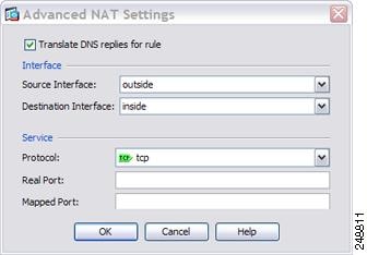
Click Advanced and configure the real and mapped interfaces and DNS modification.

Step 5

Click OK to return to the Edit Network Object dialog box, click OK again, and then click Apply.


DNS64 Reply Modification

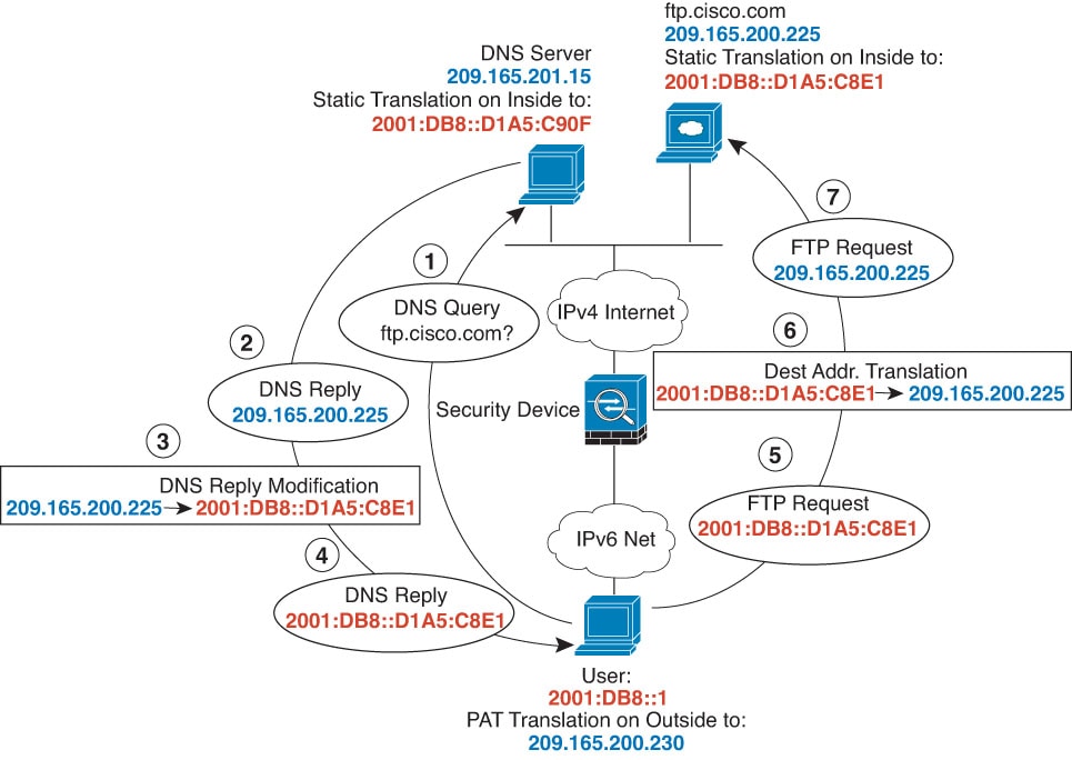
The following figure shows an FTP server and DNS server on the outside IPv4 network. The system has a static translation for the outside server. In this case, when an inside IPv6 user requests the address for ftp.cisco.com from the DNS server, the DNS server responds with the real address, 209.165.200.225.

Because you want inside users to use the mapped address for ftp.cisco.com (2001:DB8::D1A5:C8E1, where D1A5:C8E1 is the IPv6 equivalent of 209.165.200.225) you need to configure DNS reply modification for the static translation. This example also includes a static NAT translation for the DNS server, and a PAT rule for the inside IPv6 hosts.

Procedure


Step 1

Choose Configuration > Firewall > NAT.

Step 2

Configure static network object NAT with DNS modification for the FTP server.

  1. Choose Add > Network Object NAT Rule.

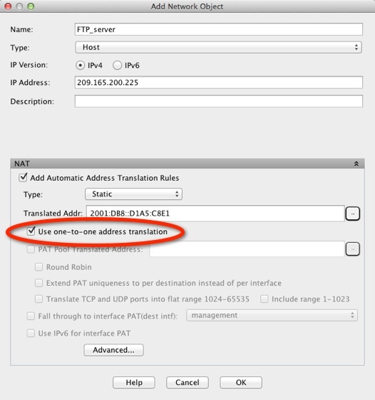
  2. Name the new network object, define the FTP server address, enable static NAT, and enter the translated address. Because this is a one-to-one translation for NAT46, select Use one-to-one address translation.

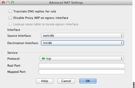
  3. Click Advanced to configure the real and mapped interfaces and DNS modification.

  4. Click OK to return to the Network Object dialog box, and click OK again to save the rule.

Step 3

Configure static network object NAT for the DNS server.

  1. Choose Add > Network Object NAT Rule.

  2. Name the new network object, define the DNS server address, enable static NAT, and enter the translated address. Because this is a one-to-one translation for NAT46, select Use one-to-one address translation.

  3. Click Advanced to configure the real and mapped interfaces.

  4. Click OK to return to the Network Object dialog box, and click OK again to save the rule.

Step 4

Configure PAT for the inside IPv6 network.

  1. Choose Add > Network Object NAT Rule.

  2. Name the new network object, define the IPv6 network address, and select Dynamic NAT.

  3. Select PAT Pool Translated Address, and click the ... (browse) button to create the PAT pool object.

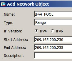
  4. In the Browse PAT Pool Translated Address dialog box, select Add > Network Object. Name the new object, enter the address range for the PAT pool, and click OK.


    IPv4_POOL object.

  5. In the Browse PAT Pool Translated Address dialog box, double-click the PAT pool object you created to select it and click OK.

  6. Click Advanced to configure the real and mapped interfaces.

  7. Click OK to return to the Network Object dialog box.

Step 5

Click OK, and then click Apply.


PTR Modification, DNS Server on Host Network

The following figure shows an FTP server and DNS server on the outside. The ASA has a static translation for the outside server. In this case, when an inside user performs a reverse DNS lookup for 10.1.2.56, the ASA modifies the reverse DNS query with the real address, and the DNS server responds with the server name, ftp.cisco.com.

Figure 18. PTR Modification, DNS Server on Host Network