Initial configuration

in body: To install Cisco Cyber Vision on a Cisco switch, you must perform the Initial configuration which steps are described in this section.

Configure the switch access

To configure each Cisco switch access refer to its corresponding installation guide available through the following links:

Check the software version

  • Check the software version using the following command in the switch's CLI:

    Show version

    To be compatible with the Cisco Cyber Vision Sensor Application:

    • the displayed version for Cisco IE3x00 and Cisco Catalyst 9x00 must be 17.02.01 or higher.

    • the displayed version for Cisco IE9x00 must be 17.09.01 or higher.

    For example: Cisco IE3400

    If the version is lower, you must update the switch firmware. To do so, follow the links to the products page in Configure the switch access.

SD Card (IE3x00/IE9x00)

If not already done, insert a 4GB Cisco SD card minimum into the switch SD card slot.

Then, you format or partition the SD card.

  • You can format the SD card for Ie3x00 using following command:

    format sdflash: ext4

Partition command is not supported on Ie9x00.

  • You can partition the SD card for Ie3x00 and Ie9x00 with following command:

    partition sdflash: iox

    Partition is intended for SD swap drive usage. For more information, refer to the corresponding switch user manual.

  • You can check the file system using the following command (check for ext4 and Read/Write):

    show sdflash: filesys

SSD Disk (Catalyst 9x00)

When a deploying a sensor on a Catalyst 9x00, you have the option to include an SSD or not. If you choose to use an SSD, follow the steps below. Otherwise, proceed to the next step: Check the date and time.

If not already done, insert a 120GB Cisco SSD disk minimum in the SSD slot.

  • You can format the SSD disk using the following command:

    format usbflash1: ext4

  • You can check the file system using the following command (check for ext4 and Read/Write):

    show usbflash1: filesys

Check date and time

The internal clock of the switch must be synchronized and configured properly.


Note


Unlike hardware sensors (i.e. Cisco IC3000) that fetch their time from the Center, the Cyber Vision IOX application sensor gets the time from the host (switch platform). Therefore, it is critical that the host synchronizes its time with the Center or a valid NTP server if it’s synchronized with the Center. If the time difference is large (hours or more), the user should adjust the Cisco IE3400 time using the Local Manager so it is close to the reference time. If not, the synchronization may take many update cycles.
  1. Check the date and time using the following command:

    Show clock

    For examples:

    Cisco IE3400:

    Cisco Catalyst 9300:

  2. If needed, adjust to the UTC time using the following command:

    clock set [hh:mm:ss] [month] [day] [year]

    Or go to the Local Manager:

    For example: Cisco IE3400

Enable IOx

Before installing the Cisco Cyber Vision sensor on the hardware, you must enable IOx.

  1. Enable IOx using the following command:

    configure terminal
    iox
    For examples:

    Cisco IE3400:

    Cisco Catalyst 9300:

  2. Check the IOx service status using the following command:

    exit
    show iox

    For examples:

    Cisco IE3400:

    Cisco Catalyst 9300:

Add the necessary configuration parameters (IE3x00)

In industrial networking environments, efficient communication between internal applications and external servers is essential for seamless operations. However, the requirement for each application to have a public routable IP address, in addition to the IP address for switch management, poses challenges for network administrators. IOS version 17.14 introduces a new feature called “L3NAT for IOx Applications” to avoid to create a dedicated IP address for a Cyber Vision sensor embedded in a IE3x00 switches. 2 solutions are available to deploy a Cyber Vision sensor:

  • The usage of a dedicated IP address for the Cyber Vision sensor

  • The new feature in IOS 17.14, "L3NAT for IOx Applications," allows you to use the switch's management IP as a proxy for all network applications.

Sensor Configuration with an External IP Address

The example of configuration given below is a simple one. This configuration is only valid if a direct link exists between the Center and the switch with the embedded sensor. In this case, the dedicated port is configured with the Collection VLAN (for example, 507). In many other cases, the port used for communication between the Center and the sensor will have to be configured as trunk.

Procedure


Step 1

Open the Cisco IE3300 10G/IE3400 CLI through ssh or via the console terminal.

Step 2

Configure a VLAN for traffic mirroring using the following commands:

configure terminal
vtp mode off
vlan 2508
remote-span
exit

The VTP off command is performed here since VTP is enabled by default and is not compatible with a high VLAN number.

If needed, select another VLAN number and use the VTP configuration requested by the network.

Step 3

Configure the AppgigabitEthernet port for communications to reach the IOx virtual application.

If communication with the sensor is done on VLAN1, the native VLAN of the Appgigabit interface must be changed to a different value, where "xxx" is the existing VLAN in the switch.

interface AppGigabitEthernet 1/1
switchport mode trunk
switchport trunk native vlan xxx
exit

Step 4

Configure the SPAN session and add to the session the interfaces to monitor:

monitor session 1 source interface Gi1/10 both
monitor session 1 destination remote vlan 2508
monitor session 1 destination format-erspan 169.254.1.2

Step 5

Configure one of the switch's ports to enable the communication between the virtual sensor and the Center:

int gi1/3
switchport access vlan 507
no shutdown

Step 6

Save the configuration using the following commands:

exit
write mem


What to do next

Once you are done with the initial configuration, proceed with the application installation and deployment following one of the procedures below with in mind the IP used in the system with the l3nat_iox feature enabled:

Sensor Configuration with Layer 3 Network Address Translation

Overview

The Layer3 Network Address Translation (L3NAT) for IOx applications is supported starting with IOS-XE release 17.14.1. This feature uses the management IP of the switch as a proxy for all applications within the routed network. The complexity and overhead associated with managing multiple public IP addresses are reduced. The IE3x00 platform supports the L3NAT feature with the Cisco Cyber Vision (CCV) IOx application. However, it cannot be used to NAT other Ethernet traffic from hosts connected to its physical Ethernet ports.

L3NAT-IOx

L3NAT is a networking technique used to translate private IP addresses in an internal network to a public IP address before packets are sent to an external network at the network layer of the OSI model. The L3NAT-IOx feature utilizes hardware components such as Application-Specific Integrated Circuits (ASICs) and Field-Programmable Gate Arrays (FPGAs) for implementation.

When a Cyber Sensor application communicates with the external CCV server, the NAT protocol translates the source private IP address of the Cyber Sensor Application to the public IP address of the Management Switched Virtual Interface (SVI) of the switch. This translation allows the packets to navigate through the external network, gives the impression that they originate from the switch management SVI IP address.

When the external CCV server communicates with the Cyber Sensor Application, the NAT protocol reverses the translation. Incoming packets addressed to the public IP address of the switch management SVI are translated to the private IP address of the destination Cyber Sensor Application. This ensures seamless communication between the application and external servers.

Guidelines and Restrictions

The guidelines and restrictions for L3NAT-IOx are as follows:

  • This feature only works with the CCV application and doesn't support any other IOx applications.

  • Only static translation is supported.

  • Translation is restricted to TCP and UDP packets exclusively.

  • Users need to set up an extra SVI on IE for the private network used by the application. The IP assigned to this SVI will act as the default gateway for the application.

  • This feature requires a Network Advantage license.

  • You can not retrieve L3NAT-IOx statistics using YANG with Network Configuration Protocol (NETCONF).

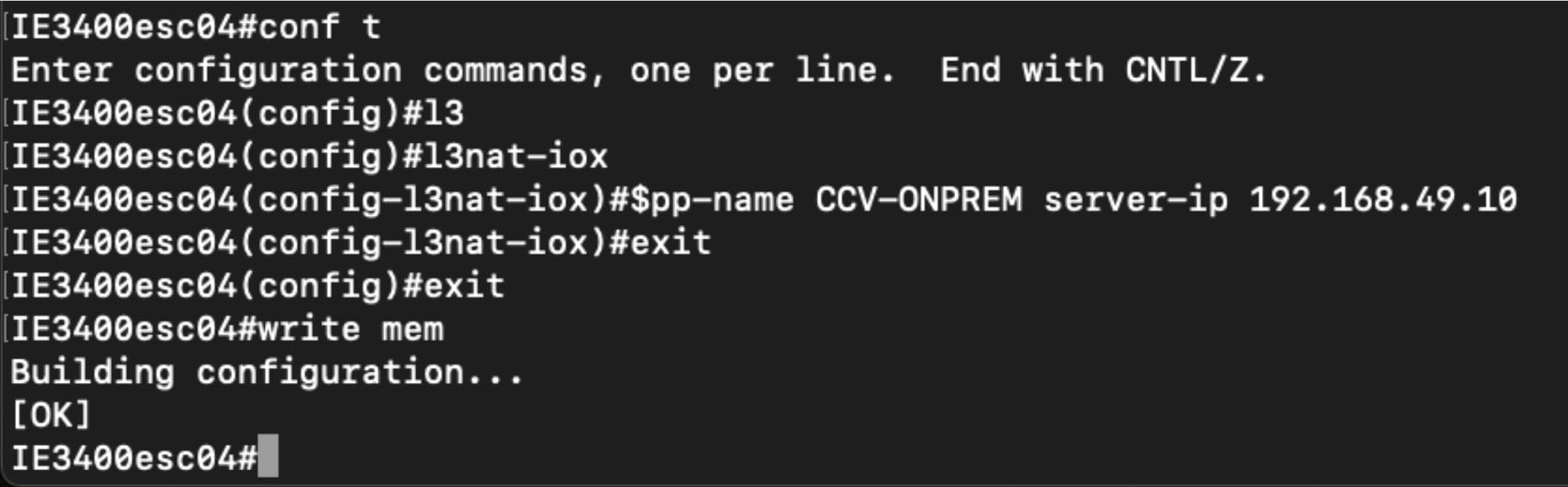
Configuring L3NAT-IOx

The configuration example is based on the following topology:

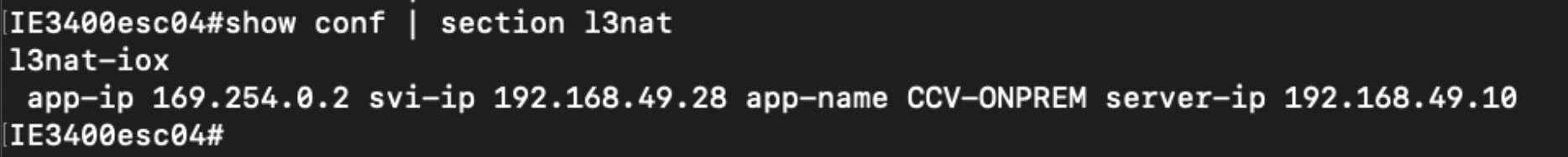
The above diagram shows application hosting on the switch using a Private IP address. The CCV sensor application is installed on the access devices connected to hosts. Devices located in the 192.168.49.0/24 network are assigned management IP addresses. The CCV sensor is installed using the private IP network 169.254.0.1/30.

Procedure


Step 1

Set up the SVI for the 169.254.0.x network with an IP address to be the default gateway for the application.

Switch(config)# int vlan 2507  

Switch(config-if)# ip address 169.254.0.1 255.255.255.252

Step 2

Set up the SVI for the 192.168.49.10/24 network with an IP address acting as the public IP to access the CCV center.

Switch(config)# int vlan 49  

Switch(config-if)# ip address 192.168.49.28 255.255.255.0

Step 3

Configure the L3NAT-IOx.

Switch# configure terminal  

Switch(config)# l3nat-iox  

Switch(config-iox-nat)# app-ip 169.254.0.2 svi-ip 192.168.49.28 app-name CCV-ONPREM server-ip 192.168.49.10 


What to do next

Once you are done with the initial configuration, proceed with the application installation and deployment following one of the procedures below with in mind the IP used in the system with the l3nat_iox feature enabled:

Configuring the Other Necessary Parameters

Procedure


Step 1

Set up a VLAN for mirroring traffic with these commands:

configure terminal 
vtp mode off 
vlan 2508 
remote-span 
exit 

The VTP off command is performed here since VTP is enabled by default and is not compatible with a high VLAN number.

If needed, select another VLAN number and use the VTP configuration requested by the network.

Step 2

Configure the AppgigabitEthernet port for communications to reach the IOx virtual application.

interface AppGigabitEthernet 1/1 

switchport mode trunk 

exit 

Step 3

Configure the SPAN session and add to the monitor:

monitor session 1 source interface Gi1/10 both 

monitor session 1 destination remote vlan 2508 

monitor session 1 destination format-erspan 169.254.1.2 

Step 4

Save the configuration using the following commands:

exit 

write mem 


What to do next

Once you are done with the initial configuration, proceed with the application installation and deployment following one of the procedures below with in mind the IP used in the system with the l3nat_iox feature enabled:

Add the necessary configuration parameters (Catalyst 9x00/IE9x00)

The configuration examples given in this section are simple ones. They are only valid if a direct link exists between the Center and the switch with the embedded sensor. In this case, the dedicated port is configured with the Collection VLAN (for example, 507). In many other cases, the port used for communication between the Center and the sensor will have to be configured as trunk.

Configuration with ERSPAN is recommended but requires routing to be enabled on the switch. If this is not possible, RSPAN is available on the Catalyst 9x00. However, note that Multicast and VLAN information will be missing with this configuration.

Configure with ERSPAN

Procedure


Step 1

Open the switch's CLI through ssh or via the console terminal.

Step 2

Configure a VLAN for traffic mirroring using the following commands:

configure terminal
ip routing
vlan 2508
exit
int vlan 2508
ip address 169.254.1.1 255.255.255.252
no shutdown 
exit

Step 3

Configure the AppGigabitEthernet port which will enable the communication to the IOx virtual application.

If communication with the sensor is done on VLAN1, the native VLAN of the Appgigabit interface must be changed to a different value, where "xxx" is the existing VLAN in the switch.

interface AppGigabitEthernet 1/0/1
switchport mode trunk
switchport trunk native vlan xxx
exit

Step 4

Configure the SPAN session and add to the session the interfaces to monitor:

Note


Disabling the ip routing command for IPv4 connections and ipv6 unicast-routing command for IPv6 connections stops ERSPAN traffic flow to the destination port. Link to Catalyst 9300 manual.

monitor session 1 type erspan-source
source interface Gi1/0/2 - 24 both
no shutdown
destination
erspan-id 2
mtu 9000
ip address 169.254.1.2
origin ip address 169.254.1.1
exit
exit

Step 5

Configure one of the switch's ports to enable the communication between the virtual sensor and the Center:

interface GigabitEthernet1/0/1
switchport access vlan 507
no shutdown
exit

Step 6

Save the configuration:

exit
write mem

What to do next

The initial configuration is now complete. Proceed with the application installation and deployment following one of the procedures below:

Configure with RSPAN (Catalyst 9x00 only)

Before you begin

The VLAN configured for RSPAN (here 2508) must be filtered on all trunk ports except for the AppGigabitEthernet interface.

Procedure


Step 1

Open the switch's CLI through ssh or via the console terminal.

Step 2

Configure a VLAN for traffic mirroring using the following commands:

configure terminal
vlan 2508
exit
int vlan 2508
remote-span
exit

Step 3

Configure the AppGigabitEthernet port which will enable the communication to the IOx virtual application.

If communication with the sensor is done on VLAN1, the native VLAN of the Appgigabit interface must be changed to a different value, where "xxx" is the existing VLAN in the switch.

interface AppGigabitEthernet 1/0/1
switchport mode trunk
switchport trunk native vlan xxx
exit

Step 4

Configure the SPAN session and add to the session the interfaces to monitor:

monitor session 1 source interface Gi1/0/2 - 24 both
monitor session 1 destination remote vlan 2508

Step 5

Configure one of the switch's ports to enable the communication between the virtual sensor and the Center:

interface GigabitEthernet1/0/1
switchport access vlan 507
no shutdown
exit

Step 6

Save the configuration:

exit
write mem

What to do next

The initial configuration is now complete. Proceed with the application installation and deployment following one of the procedures below: