Interfaces

The following topics explain how to configure the interfaces on your Firepower Threat Defense device.

About FTD Interfaces

FTD includes data interfaces as well as a Management/Diagnostic interface.

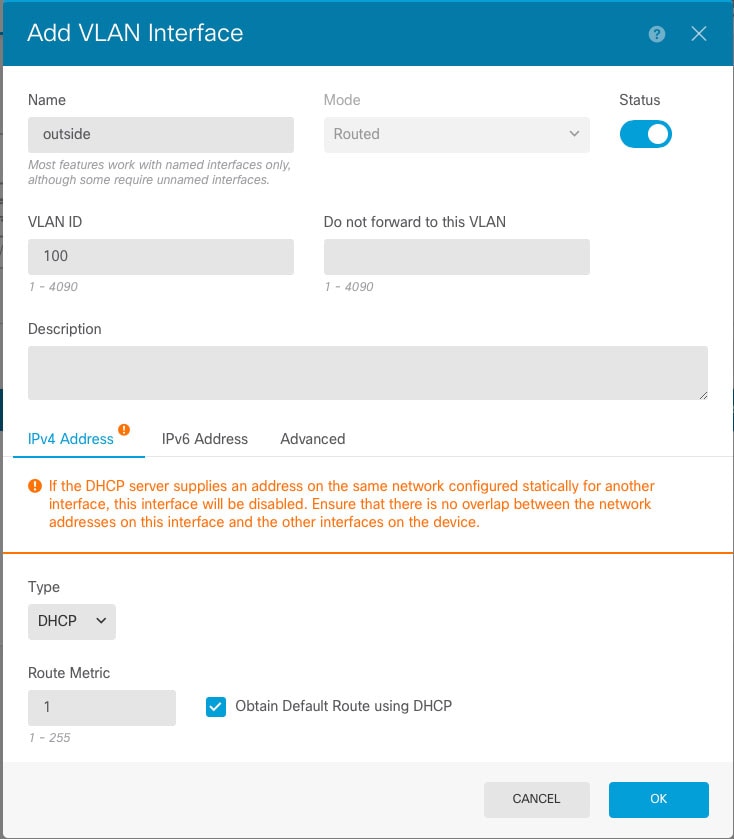
When you attach a cable to an interface connection (physically or virtually), you need to configure the interface. At minimum, you need to name the interface and enable it for it to pass traffic. If the interface is a member of a bridge group, this is sufficient. For non-bridge group members, you also need to give the interface an IP address. If you intend to create VLAN subinterfaces rather than a single physical interface on a given port, you would typically configure the IP addresses on the subinterface, not on the physical interface. VLAN subinterfaces let you divide a physical interface into multiple logical interfaces that are tagged with different VLAN IDs, which is useful when you connect to a trunk port on a switch. You do not configure IP addresses on passive interfaces.

The Interfaces page include sub-pages for interface types: Interfaces (for physical interfaces), Bridge Groups, EtherChannels, and VLANs (for the Firepower 1010). Note that Firepower 4100/9300 EtherChannels are listed on the Interfaces page and not on the EtherChannel page, because you can only modify EtherChannel parameters in FXOS, not in the FDM. Each page shows the available interfaces, their names, addresses, modes, and states. You can change the state of an interface, on or off, directly in the list of interfaces. The list shows the interface characteristics based on your configuration. Use the open/close arrow on a bridge group, EtherChannel, or VLAN interface to view the member interfaces, which also appear by themselves in the appropriate list. You can also view subinterfaces for supported parent interfaces. For information on how these interfaces map to virtual interfaces and network adapters, see How VMware Network Adapters and Interfaces Map to the FTD Physical Interfaces.

The following topics explain the limitations of configuring interfaces through the FDM as well as other interface management concepts.

Interface Modes

You can configure one of the following modes for each interface:

Routed

Each Layer 3 routed interface requires an IP address on a unique subnet. You would typically attach these interfaces to switches, a port on another router, or to an ISP/WAN gateway.

Passive

Passive interfaces monitor traffic flowing across a network using a switch SPAN (Switched Port Analyzer) or mirror port. The SPAN or mirror port allows for traffic to be copied from other ports on the switch. This function provides the system visibility within the network without being in the flow of network traffic. When configured in a passive deployment, the system cannot take certain actions such as blocking or shaping traffic. Passive interfaces receive all traffic unconditionally and no traffic received on these interfaces is retransmitted.

Switch Port (Firepower 1010)
Switch ports forward traffic at Layer 2, using the switching function in hardware. Switch ports on the same VLAN can communicate with each other using hardware switching, and traffic is not subject to the Firepower Threat Defense security policy. Access ports accept only untagged traffic, and you can assign them to a single VLAN. Trunk ports accept untagged and tagged traffic, and can belong to more than one VLAN. You cannot configure the Management interface as a switch port.
BridgeGroupMember

A bridge group is a group of interfaces that the Firepower Threat Defense device bridges instead of routes. All interfaces are on the same network. The bridge group is represented by a Bridge Virtual Interface (BVI) that has an IP address on the bridge network.

You can route between routed interfaces and BVIs, if you name the BVI. In this case, the BVI acts as the gateway between member interfaces and routed interfaces. If you do not name the BVI, traffic on the bridge group member interfaces cannot leave the bridge group. Normally, you would name the interface so that you can route member interfaces to the internet.

One use for a bridge group in routed mode is to use extra interfaces on the Firepower Threat Defense device instead of an external switch. You can attach endpoints directly to bridge group member interfaces. You can also attach switches to add more endpoints to the same network as the BVI.

Management/Diagnostic Interface

The physical port labeled Management (or for the FTDv, the Management0/0 virtual interface) actually has two separate interfaces associated with it.

  • Management virtual interface—This IP address is used for system communication. This is the address the system uses for Smart Licensing and to retrieve database updates. You can open management sessions to it (FDM and CLI). You must configure a management address, which is defined on System Settings > Management Interface.

  • Diagnostic virtual interface—You can use this interface to send syslog messages to an external syslog server. Configuring an IP address for the Diagnostic interface is optional. The main reason to configure the interface is if you want to use it for syslog messages. This interface appears, and is configurable, on the Device > Interfaces page. The Diagnostic interface only allows management traffic, and does not allow through traffic.

(Hardware devices.) One way to configure Management/Diagnostic is to not wire the physical port to a network. Instead, configure the Management IP address only, and configure it to use the data interfaces as the gateway for obtaining updates from the internet. Then, open the inside interfaces to HTTPS/SSH traffic (by default, HTTPS is enabled) and open the FDM using the inside IP address (see Configuring the Management Access List).

For the FTDv, the recommended configuration is to attach Management0/0 to the same network as the inside interface, and use the inside interface as the gateway. Do not configure a separate address for Diagnostic.

Recommendations for Configuring a Separate Management Network

(Hardware devices.) If you want to use a separate management network, wire the physical Management interface to a switch or router.

For FTDv, attach Management0/0 to a separate network from any of the data interfaces. If you are still using the default IP addresses, you will need to change either the management IP address or the inside interface IP address, as they are on the same subnet.

Then, configure the following:

  • Select Device > System Settings > Management Interface and configure IPv4 or IPv6 addresses (or both) on the attached network. If you want to, you can configure a DHCP server to provide IPv4 addresses to other endpoints on the network. If there is a router with a route to the internet on the management network, use that as the gateway. Otherwise, use the data interfaces as the gateway.

  • Configure an address for the Diagnostic interface (on Device > Interfaces) only if you intend to send syslog messages through the interface to a syslog server. Otherwise, do not configure an address for Diagnostic; it is not needed. Any IP address you configure must be on the same subnet as the management IP address and cannot be the in DHCP server pool. For example, if you use 192.168.45.45 as the management address, and 192.168.45.46-192.168.45.254 as the DHCP pool, you can configure Diagnostic using any address from 192.168.45.1 to 192.168.45.44.

Limitations for Management/Diagnostic Interface Configuration for a Separate Management Network

If you wire the physical Management interface, or for FTDv, you attach Management0/0 to a separate network, ensure that you follow these limitations:

  • If you want a DHCP server on the management network, configure it on the Management interface (Device > System Settings > Management Interface). You cannot configure a DHCP server on the Diagnostic interface.

  • If there is another DHCP server on the management network, disable it or the DHCP server running on Management. As a rule, a given subnet should have no more than one DHCP server.

  • If you configure addresses for both Management and Diagnostic, ensure that they are on the same subnet.

  • (Hardware devices only.) You can use the data interfaces as the management gateway even if you configure an IP address for Diagnostic. But Diagnostic will not use the data interfaces as a gateway. If you need a path from Diagnostic to other networks, another router on the management network needs to route the traffic originating from the Diagnostic IP address. If necessary, configure static routes for the Diagnostic interface (select Device > Routing).

Security Zones

Each interface can be assigned to a single security zone. You then apply your security policy based on zones. For example, you can assign the inside interface to the inside zone; and the outside interface to the outside zone. You can configure your access control policy to enable traffic to go from inside to outside, but not from outside to inside, for example.

Each zone has a mode that relates directly to the interface mode. You can add interfaces to the same mode security zone only.

For bridge groups, you add member interfaces to the zones, you cannot add the Bridge Virtual Interface (BVI).

You do not include the Management/Diagnostic interface in a zone. Zones apply to data interfaces only.

You can create security zones on the Objects page.

IPv6 Addressing

You can configure two types of unicast addresses for IPv6:

  • Global—The global address is a public address that you can use on the public network. For a bridge group, you configure the global address on the Bridge Virtual Interface (BVI), not on each member interface. You cannot specify any of the following as a global address.

    • Internally reserved IPv6 addresses: fd00::/56 (from=fd00:: to= fd00:0000:0000:00ff:ffff:ffff:ffff:ffff)

    • An unspecified address, such as ::/128

    • The loopback address, ::1/128

    • multicast addresses, ff00::/8

    • Link-local addresses, fe80::/10

  • Link-local—The link-local address is a private address that you can only use on the directly-connected network. Routers do not forward packets using link-local addresses; they are only for communication on a particular physical network segment. They can be used for address configuration or for the Network Discovery functions such as address resolution and neighbor discovery. In a bridge group, enabling IPv6 on the BVI automatically configures link-local addresses for each bridge group member interface. Each interface must have its own address because the link-local address is only available on a segment, and is tied to the interface MAC address.

At a minimum, you need to configure a link-local address for IPv6 to operate. If you configure a global address, a link-local address is automatically configured on the interface, so you do not also need to specifically configure a link-local address. If you do not configure a global address, then you need to configure the link-local address, either automatically or manually.

Auto-MDI/MDIX Feature

For RJ-45 interfaces, the default auto-negotiation setting also includes the Auto-MDI/MDIX feature. Auto-MDI/MDIX eliminates the need for crossover cabling by performing an internal crossover when a straight cable is detected during the auto-negotiation phase. Either the speed or duplex must be set to auto-negotiate to enable Auto-MDI/MDIX for the interface. If you explicitly set both the speed and duplex to a fixed value, thus disabling auto-negotiation for both settings, then Auto-MDI/MDIX is also disabled. For Gigabit Ethernet, when the speed and duplex are set to 1000 and full, then the interface always auto-negotiates; therefore Auto-MDI/MDIX is always enabled and you cannot disable it.

Guidelines and Limitations for Interfaces

The following topics cover some of the limitations for interfaces.

Limitations for Interface Configuration

When you use the FDM to configure the device, there are several limitations to interface configuration. If you need any of the following features, you must use the FMC to configure the device.

  • Routed firewall mode only is supported. You cannot configure transparent firewall mode interfaces.

  • You can configure passive interfaces, but not ERSPAN interfaces.

  • You cannot configure interfaces to be inline (in an inline set), or inline tap, for IPS-only processing. IPS-only mode interfaces bypass many firewall checks and only support IPS security policy. In comparison, Firewall mode interfaces subject traffic to firewall functions such as maintaining flows, tracking flow states at both IP and TCP layers, IP defragmentation, and TCP normalization. You can also optionally configure IPS functions for this firewall mode traffic according to your security policy.

  • You cannot configure redundant interfaces.

  • You can configure EtherChannels in the FDM for the following models: Firepower 1000, Firepower 2100. The Firepower 4100/9300 supports EtherChannels, but you must perform all hardware configuration of EtherChannels in FXOS on the chassis. Firepower 4100/9300 EtherChannels appear in the FDM Interfaces page alongside single physical interfaces.

  • You can only add one bridge group.

  • FTD supports IPv4 PPPoE on routed interfaces only. PPPoE is not supported on High Availability units.

Maximum Number of VLAN Subinterfaces by Device Model

The device model limits the maximum number of VLAN subinterfaces that you can configure. Note that you can configure subinterfaces on data interfaces only, you cannot configure them on the management interface.

The following table explains the limits for each device model.

Model

Maximum VLAN Subinterfaces

Firepower 1010

60

Firepower 1120

512

Firepower 1140, 1150

1024

Firepower 2100

1024

Firepower 4100

1024

Firepower 9300

1024

FTDv

50

ASA 5508-X

50

ASA 5516-X

100

ASA 5525-X

200

ASA 5545-X

300

ASA 5555-X

500

ISA 3000

100

Configure a Physical Interface

At minimum, you must enable a physical interface to use it. You would also typically name it and configure IP addressing. You would not configure IP addressing if you intend to create VLAN subinterfaces, if you are configuring a passive mode interface, or if you intend to add the interface to a bridge group. Firepower 4100/9300 EtherChannels appear in the FDM Interfaces page alongside single physical interfaces, and this procedure also applies to those EtherChannels. You must perform all hardware configuration of Firepower 4100/9300 EtherChannels in FXOS on the chassis.


Note


To configure physical interfaces as Firepower 1010 switch ports, see Configure VLAN Interfaces and Switch Ports (Firepower 1010).

To configure physical interfaces as passive interfaces, see Configure a Physical Interface in Passive Mode.


You can disable an interface to temporarily prevent transmission on the connected network. You do not need to remove the interface's configuration.

Procedure


Step 1

Click Device, and then click the link in the Interfaces summary.

The Interfaces page is selected by default. The interfaces list shows physical interfaces, their names, addresses, and states.

Step 2

Click the edit icon (edit icon) for the physical interface you want to edit.

You cannot edit an interface that you are using as the failover or stateful failover link in a high availability configuration.

Step 3

Set the following:

  1. Set the Interface Name.

    Set the name for the interface, up to 48 characters. Alphabetic characters must be lower case. For example, inside or outside. Without a name, the rest of the interface configuration is ignored. Unless you configure subinterfaces, the interface should have a name. Note: Do not configure the name for an interface that you want to add to an EtherChannel.

    Note


    If you change the name, the change is automatically reflected everywhere you used the old name, including security zones, syslog server objects, and DHCP server definitions. However, you cannot remove the name until you first remove all configurations that use the name, because you typically cannot use an unnamed interface for any policy or setting.

  2. Choose the Mode.

    • Routed—Routed mode interfaces subject traffic to all firewall functions, including maintaining flows, tracking flow states at both IP and TCP layers, IP defragmentation, and TCP normalization, and your firewall policies. This is the normal interface mode.

    • Passive—Passive interfaces monitor traffic flowing across a network using a switch SPAN or mirror port. The SPAN or mirror port allows for traffic to be copied from other ports on the switch. This function provides the system visibility within the network without being in the flow of network traffic. When configured in a passive deployment, the system cannot take certain actions such as blocking or shaping traffic. Passive interfaces receive all traffic unconditionally and no traffic received on these interfaces is retransmitted. If you select this mode, do not following the rest of this procedure. Instead, see Configure a Physical Interface in Passive Mode. Note that you cannot configure IP addresses on passive interfaces.

    • Switch Port—(Firepower 1010) Switch ports allow hardware switching between ports on the same VLAN. Switched traffic is not subject to the security policy. If you select this mode, do not following the rest of this procedure. Instead, see Configure VLAN Interfaces and Switch Ports (Firepower 1010)

    If you later add this interface to a bridge group, the mode will automatically change to BridgeGroupMember. Note that you cannot configure IP addresses on bridge group member interfaces.

  3. Set the Status slider to the enabled setting (Enabled slider.).

    For interfaces on a Firepower 4100/9300 device, you must also enable the interface in FXOS.

    If you intend to configure subinterfaces for this physical interface, you are probably done. Click Save and continue with Configure VLAN Subinterfaces and 802.1Q Trunking. Otherwise, continue.

    Note


    Even when configuring subinterfaces, it is valid to name the interface and supply IP addresses. This is not the typical setup, but if you know that is what you need, you can configure it.

  4. (Optional) Set the Description.

    The description can be up to 200 characters on a single line, without carriage returns.

Step 4

Click the IPv4 Address tab and configure the IPv4 address.

Select one of the following options from the Type field:

  • DHCP—Choose this option if the address should be obtained from the DHCP server on the network. You cannot use this option if you configure high availability. Change the following options if necessary:

    • Route Metric—If you obtain the default route from the DHCP server, the administrative distance to the learned route, between 1 and 255. The default is 1.

    • Obtain Default Route—Whether to get the default route from the DHCP server. You would normally select this option, which is the default.

  • Static—Choose this option if you want to assign an address that should not change. Type in the interface's IP address and the subnet mask for the network attached to the interface. For example, if you attach the 10.100.10.0/24 network, you could enter 10.100.10.1/24. Ensure that the address is not already used on the network.

    If you configured high availability, and you are monitoring this interface for HA, also configure a standby IP address on the same subnet. The standby address is used by this interface on the standby device. If you do not set the standby IP address, the active unit cannot monitor the standby interface using network tests; it can only track the link state.

    Note


    If there is a DHCP server configured for the interface, you are shown the configuration. You can edit or delete the DHCP address pool. If you change the interface IP address to a different subnet, you must either delete the DHCP server, or configure an address pool on the new subnet, before you can save the interface changes. See Configuring the DHCP Server.

  • PPPoE—Choose this option if the address should be obtained using Point-to-point Protocol over Ethernet (PPPoE). PPPoE may be required if the interface is connected to a DSL modem, cable modem, or other connection to your ISP, and your ISP uses PPPoE to provide your IP address. You cannot use this option if you configure High Availability. Set the following values:

    • Group Name—Specify a group name of your choice to represent this connection.

    • PPPoE Username—Specify the username provided by your ISP.

    • PPPoE Password—Specify the password provided by your ISP.

    • PPP Authentication—Choose PAP, CHAP, or MSCHAP.

      PAP passes a cleartext username and password during authentication and is not secure. With CHAP, the client returns the encrypted [challenge plus password], with a cleartext username in response to the server challenge. CHAP is more secure than PAP, but it does not encrypt data. MSCHAP is similar to CHAP but is more secure because the server stores and compares only encrypted passwords rather than cleartext passwords as in CHAP. MSCHAP also generates a key for data encryption by MPPE.

    • PPPoE Learned Route Metric—Assign an administrative distance to the learned route. Valid values are from 1 to 255. By default, the administrative distance for the learned routes is 1.

    • Obtain Default Route from PPPoE—Check this check box to enable obtaining the default route from the PPPoE server.

    • IP Address Type—Choose Dynamic to obtain the IP address from the PPPoE server. You can alternatively choose Static if you were assigned a static IP address from the ISP.

Step 5

(Optional.) Click the IPv6 Address tab and configure the IPv6 address.

  • State—To enable IPv6 processing and to automatically configure the link-local address when you do not configure the global address, select Enabled. The link local address is generated based on the interface MAC addresses (Modified EUI-64 format).

    Note


    Disabling IPv6 does not disable IPv6 processing on an interface that is configured with an explicit IPv6 address or that is enabled for autoconfiguration.

  • Address Auto Configuration—Select this option to have the address automatically configured. IPv6 stateless autoconfiguration will generate a global IPv6 address only if the link on which the device resides has a router configured to provide IPv6 services, including the advertisement of an IPv6 global prefix for use on the link. If IPv6 routing services are not available on the link, you will get a link-local IPv6 address only, which you cannot access outside of the device's immediate network link. The link local address is based on the Modified EUI-64 interface ID.

    Although RFC 4862 specifies that hosts configured for stateless autoconfiguration do not send Router Advertisement messages, the FTD device does send Router Advertisement messages in this case. Select Suppress RA to suppress messages and conform to the RFC.

  • Static Address/Prefix—If you do not use stateless autoconfiguration, enter the full static global IPv6 address and network prefix. For example, 2001:0DB8::BA98:0:3210/48. For more information on IPv6 addressing, see IPv6 Addressing.

    If you want to use the address as link local only, select the Link - Local option. Link local addresses are not accessible outside the local network. You cannot configure a link-local address on a bridge group interface.

    Note


    A link-local address should start with FE8, FE9, FEA, or FEB, for example fe80::20d:88ff:feee:6a82. Note that we recommend automatically assigning the link-local address based on the Modified EUI-64 format. For example, if other devices enforce the use of the Modified EUI-64 format, then a manually-assigned link-local address may cause packets to be dropped.

  • Standby IP Address—If you configure high availability, and you are monitoring this interface for HA, also configure a standby IPv6 address on the same subnet. The standby address is used by this interface on the standby device. If you do not set the standby IP address, the active unit cannot monitor the standby interface using network tests; it can only track the link state.

  • Suppress RA—Whether to suppress router advertisements. The FTD can participate in router advertisements so that neighboring devices can dynamically learn a default router address. By default, router advertisement messages (ICMPv6 Type 134) are periodically sent out each IPv6 configured interface.

    Router advertisements are also sent in response to router solicitation messages (ICMPv6 Type 133). Router solicitation messages are sent by hosts at system startup so that the host can immediately autoconfigure without needing to wait for the next scheduled router advertisement message.

    You might want to suppress these messages on any interface for which you do not want the FTD device to supply the IPv6 prefix (for example, the outside interface).

Step 6

(Optional.) Configure Advanced Options.

The advanced settings have defaults that are appropriate for most networks. Edit them only if you are resolving network issues.

Step 7

Click OK.


What to do next

Configure Bridge Groups

A bridge group is a virtual interface that groups one or more interfaces. The main reason to group interfaces is to create a group of switched interfaces. Thus, you can attach workstations or other endpoint devices directly to the interfaces included in the bridge group. You do not need to connect them through a separate physical switch, although you can also attach a switch to a bridge group member.

The group members do not have IP addresses. Instead, all member interfaces share the IP address of the Bridge Virtual Interface (BVI). If you enable IPv6 on the BVI, member interfaces are automatically assigned unique link-local addresses.

You enable and disable the member interfaces individually. Thus, you can disable any unused interfaces without needing to remove them from the bridge group. The bridge group itself is always enabled.

You typically configure a DHCP server on the bridge group interface (BVI), which provides IP addresses for any endpoints connected through member interfaces. However, you can configure static addresses on the endpoints connected to the member interfaces if you prefer. All endpoints within the bridge group must have IP addresses on the same subnet as the bridge group IP address.

Guidelines and Limitations

  • You can add one bridge group.

  • FDM-defined EtherChannels are not supported as bridge group members. EtherChannels on the Firepower 4100/9300 can be bridge group members.

  • You cannot configure bridge groups on Firepower 2100 series or FTDv devices.

  • For the Firepower 1010, you cannot mix logical VLAN interfaces and physical firewall interfaces in the same bridge group.

  • The ISA 3000 comes pre-configured with bridge group BVI1 (not named, which means it does not participate in routing). BVI1 includes all data interfaces: GigabitEthernet1/1 (outside1), GigabitEthernet1/2 (inside1), GigabitEthernet1/3 (outside2), and GigabitEthernet1/4 (inside2). You must set the BVI1 IP address to match your network.

Before you begin

Configure the interfaces that will be members of the bridge group. Specifically, each member interface must meet the following requirements:

  • The interface must have a name.

  • The interface cannot have any IPv4 or IPv6 addresses defined for it, either static or served through DHCP. If you need to remove the address from an interface that you are currently using, you might also need to remove other configurations for the interface, such as static routes, DHCP server, or NAT rules, that depend on the interface having an address.

  • You must remove the interface from its security zone (if it is in a zone), and delete any NAT rules for the interface, before you can add it to a bridge group.

Procedure


Step 1

Click Device, click the link in the Interfaces summary, then click Bridge Groups.

The bridge groups list shows existing bridge groups. Click the open/close arrow to view the member interfaces for each bridge group. Member interfaces also appear separately on the Interfaces or VLANs pages.

Step 2

Do one of the following:

  • Click the edit icon (edit icon) for the BVI1 bridge group.

  • Click Create Bridge Group or the plus icon (Plus icon.) to create a new group.

    Note


    You can have a single bridge group. If you already have a bridge group defined, you should edit that group instead of trying to create a new one. If you need to create a new bridge group, you must first delete the existing bridge group.

  • Click the delete icon (delete icon) for the bridge group if you no longer need it. When you delete a bridge group, its members become standard routed interfaces, and any NAT rules or security zone membership are retained. You can edit the interfaces to give them IP addresses. If you want to add them to a new bridge group, first you need to remove the NAT rules and remove the interface from its security zone.

Step 3

Configure the following:

  1. (Optional) Set the Interface Name.

    Set the name for the bridge group, up to 48 characters. Alphabetic characters must be lower case. For example, inside or outside. Set the name if you want this BVI to participate in routing between it and other named interfaces.

    Note


    If you change the name, the change is automatically reflected everywhere you used the old name, including security zones, syslog server objects, and DHCP server definitions. However, you cannot remove the name until you first remove all configurations that use the name, because you typically cannot use an unnamed interface for any policy or setting.

  2. (Optional) Set the Description.

    The description can be up to 200 characters on a single line, without carriage returns.

  3. Edit the Bridge Group Members list.

    You can add up to 64 interfaces or subinterfaces to a single bridge group.

    • Add an interface—Click the plus icon (Plus icon.) , click one or more interfaces, and then click OK.

    • Remove an interface—Mouse over an interface and click the x on the right side.

Step 4

Click the IPv4 Address tab and configure the IPv4 address.

Select one of the following options from the Type field:

  • Static—Choose this option if you want to assign an address that should not change. Type in the bridge group's IP address and the subnet mask. All attached endpoints will be on this network. Ensure that the address is not already used on the network.

    If you configured high availability, and you are monitoring this interface for HA, also configure a standby IP address on the same subnet. The standby address is used by this interface on the standby device. If you do not set the standby IP address, the active unit cannot monitor the standby interface using network tests; it can only track the link state.

    Note


    If there is a DHCP server configured for the interface, you are shown the configuration. You can edit or delete the DHCP address pool. If you change the interface IP address to a different subnet, you must either delete the DHCP server, or configure an address pool on the new subnet, before you can save the interface changes. See Configuring the DHCP Server.

  • Dynamic (DHCP)—Choose this option if the address should be obtained from the DHCP server on the network. This is not the typical option for bridge groups, but you can configure it if needed. You cannot use this option if you configure high availability.Change the following options if necessary:

    • Route Metric—If you obtain the default route from the DHCP server, the administrative distance to the learned route, between 1 and 255. The default is 1.

    • Obtain Default Route—Whether to get the default route from the DHCP server. You would normally select this option, which is the default.

Step 5

(Optional.) Click the IPv6 Address tab and configure the IPv6 address.

  • State—To enable IPv6 processing and to automatically configure the link-local address when you do not configure the global address, select Enabled. The link local address is generated based on the interface MAC addresses (Modified EUI-64 format).

    Note


    Disabling IPv6 does not disable IPv6 processing on an interface that is configured with an explicit IPv6 address or that is enabled for autoconfiguration.

  • Static Address/Prefix—If you do not use stateless autoconfiguration, enter the full static global IPv6 address and network prefix. For example, 2001:0DB8::BA98:0:3210/48. For more information on IPv6 addressing, see IPv6 Addressing.

    If you want to use the address as link local only, select the Link - Local option. Link local addresses are not accessible outside the local network. You cannot configure a link-local address on a bridge group interface.

    Note


    A link-local address should start with FE8, FE9, FEA, or FEB, for example fe80::20d:88ff:feee:6a82. Note that we recommend automatically assigning the link-local address based on the Modified EUI-64 format. For example, if other devices enforce the use of the Modified EUI-64 format, then a manually-assigned link-local address may cause packets to be dropped.

  • Standby IP Address—If you configure high availability, and you are monitoring this interface for HA, also configure a standby IPv6 address on the same subnet. The standby address is used by this interface on the standby device. If you do not set the standby IP address, the active unit cannot monitor the standby interface using network tests; it can only track the link state.

  • Suppress RA—Whether to suppress router advertisements. The FTD device can participate in router advertisements so that neighboring devices can dynamically learn a default router address. By default, router advertisement messages (ICMPv6 Type 134) are periodically sent out each IPv6 configured interface.

    Router advertisements are also sent in response to router solicitation messages (ICMPv6 Type 133). Router solicitation messages are sent by hosts at system startup so that the host can immediately autoconfigure without needing to wait for the next scheduled router advertisement message.

    You might want to suppress these messages on any interface for which you do not want the FTD device to supply the IPv6 prefix (for example, the outside interface).

Step 6

(Optional.) Configure Advanced Options.

You configure most advanced options on bridge group member interfaces, but some are available for the bridge group interface.

The advanced settings have defaults that are appropriate for most networks. Edit them only if you are resolving network issues.

Step 7

Click OK.


What to do next

  • Ensure that all member interfaces that you intend to use are enabled.

  • Configure a DHCP server for the bridge group. See Configuring the DHCP Server.

  • Add the member interfaces to the appropriate security zones. See Configuring Security Zones.

  • Ensure that policies, such as identity, NAT, and access, supply the required services for the bridge group and member interfaces.

Configure EtherChannels

This section describes EtherChannels and how to configure them.


Note


You can add EtherChannels in the FDM to the following models:

  • Firepower 1000

  • Firepower 2100

The Firepower 4100/9300 supports EtherChannels, but you must perform all hardware configuration of EtherChannels in FXOS on the chassis. Firepower 4100/9300 EtherChannels appear in the FDM Interfaces page alongside single physical interfaces. You also cannot configure EtherChannels in the FDM on other models, such as the FTDv or ASA 5500-X series.


About EtherChannels

An 802.3ad EtherChannel is a logical interface (called a port-channel interface) consisting of a bundle of individual Ethernet links (a channel group) so that you increase the bandwidth for a single network. A port channel interface is used in the same way as a physical interface when you configure interface-related features.

You can configure up to 48 EtherChannels, depending on how many interfaces your model supports.

Channel Group Interfaces

Each channel group can have up to 8 active interfaces.

All interfaces in the channel group must be the same type and speed. The first interface added to the channel group determines the correct type and speed.

The EtherChannel aggregates the traffic across all the available active interfaces in the channel. The interface is selected using a proprietary hash algorithm, based on source or destination MAC addresses, IP addresses, TCP and UDP port numbers and VLAN numbers.

Connecting to an EtherChannel on Another Device

The device to which you connect the FTD EtherChannel must also support 802.3ad EtherChannels; for example, you can connect to the Catalyst 6500 switch or the Cisco Nexus 7000.

When the switch is part of a Virtual Switching System (VSS) or Virtual Port Channel (vPC), then you can connect FTD interfaces within the same EtherChannel to separate switches in the VSS/vPC. The switch interfaces are members of the same EtherChannel port-channel interface, because the separate switches act like a single switch.

Figure 1. Connecting to a VSS/vPC

Note


If the FTD device is in transparent firewall mode, and you place the FTD device between two sets of VSS/vPC switches, then be sure to disable Unidirectional Link Detection (UDLD) on any switch ports connected to the FTD device with an EtherChannel. If you enable UDLD, then a switch port may receive UDLD packets sourced from both switches in the other VSS/vPC pair. The receiving switch will place the receiving interface in a down state with the reason "UDLD Neighbor mismatch".


If you use the FTD device in an Active/Standby failover deployment, then you need to create separate EtherChannels on the switches in the VSS/vPC, one for each FTD device. On each FTD deivce, a single EtherChannel connects to both switches. Even if you could group all switch interfaces into a single EtherChannel connecting to both FTD devices (in this case, the EtherChannel will not be established because of the separate FTD system IDs), a single EtherChannel would not be desirable because you do not want traffic sent to the standby FTD device.

Figure 2. Active/Standby Failover and VSS/vPC

Link Aggregation Control Protocol

The Link Aggregation Control Protocol (LACP) aggregates interfaces by exchanging the Link Aggregation Control Protocol Data Units (LACPDUs) between two network devices.

You can configure each physical interface in an EtherChannel to be:

  • Active—Sends and receives LACP updates. An active EtherChannel can establish connectivity with either an active or a passive EtherChannel. You should use the active mode unless you need to minimize the amount of LACP traffic.

  • On—The EtherChannel is always on, and LACP is not used. An “on” EtherChannel can only establish a connection with another “on” EtherChannel.

LACP coordinates the automatic addition and deletion of links to the EtherChannel without user intervention. It also handles misconfigurations and checks that both ends of member interfaces are connected to the correct channel group. “On” mode cannot use standby interfaces in the channel group when an interface goes down, and the connectivity and configurations are not checked.

Load Balancing

The FTD device distributes packets to the interfaces in the EtherChannel by hashing the source and destination IP address of the packet (this criteria is configurable). The resulting hash is divided by the number of active links in a modulo operation where the resulting remainder determines which interface owns the flow. All packets with a hash_value mod active_links result of 0 go to the first interface in the EtherChannel, packets with a result of 1 go to the second interface, packets with a result of 2 go to the third interface, and so on. For example, if you have 15 active links, then the modulo operation provides values from 0 to 14. For 6 active links, the values are 0 to 5, and so on.

If an active interface goes down and is not replaced by a standby interface, then traffic is rebalanced between the remaining links. The failure is masked from both Spanning Tree at Layer 2 and the routing table at Layer 3, so the switchover is transparent to other network devices.

EtherChannel MAC Address

All interfaces that are part of the channel group share the same MAC address. This feature makes the EtherChannel transparent to network applications and users, because they only see the one logical connection; they have no knowledge of the individual links.

Firepower Hardware

The port-channel interface uses the MAC address of the internal interface Internal-Data 0/1. Alternatively you can manually configure a MAC address for the port-channel interface. All EtherChannel interfaces on a chassis use the same MAC address, so be aware that if you use SNMP polling, for example, multiple interfaces will have the same MAC address.


Note


Member interfaces only use the Internal-Data 0/1 MAC address after a reboot. Prior to rebooting, the member interface uses its own MAC address. If you add a new member interface after a reboot, you will have to perform another reboot to update its MAC address.


ASA Hardware

The port-channel interface uses the lowest numbered channel group interface MAC address as the port-channel MAC address. Alternatively you can manually configure a MAC address for the port-channel interface. We recommend manually configuring a unique MAC address in case the group channel interface membership changes. If you remove the interface that was providing the port-channel MAC address, then the port-channel MAC address changes to the next lowest numbered interface, thus causing traffic disruption.

Guidelines for EtherChannels

Bridge Group

FDM-defined EtherChannels are not supported as bridge group members. EtherChannels on the Firepower 4100/9300 can be bridge group members.

High Availability

  • When you use an EtherChannel interface as a High Availability link, it must be pre-configured on both units in the High Availability pair; you cannot configure it on the primary unit and expect it to replicate to the secondary unit because the High Availability link itself is required for replication.

  • If you use an EtherChannel interface for the state link, no special configuration is required; the configuration can replicate from the primary unit as normal. For the Firepower 4100/9300 chassis, all interfaces, including EtherChannels, need to be pre-configured on both units.

  • You can monitor EtherChannel interfaces for High Availability. When an active member interface fails over to a standby interface, this activity does not cause the EtherChannel interface to appear to be failed when being monitored for device-level High Availability. Only when all physical interfaces fail does the EtherChannel interface appear to be failed.

  • If you use an EtherChannel interface for a High Availability or state link, then to prevent out-of-order packets, only one interface in the EtherChannel is used. If that interface fails, then the next interface in the EtherChannel is used. You cannot alter the EtherChannel configuration while it is in use as a High Availability link. To alter the configuration, you need to temporarily disable High Availability, which prevents High Availability from occurring for the duration.

Model Support

  • You can add EtherChannels in the FDM to the following models:

    • Firepower 1000

    • Firepower 2100

    The Firepower 4100/9300 supports EtherChannels, but you must perform all hardware configuration of EtherChannels in FXOS on the chassis. Firepower 4100/9300 EtherChannels appear in the FDM Interfaces page alongside single physical interfaces. You also cannot configure EtherChannels in FDM on other models, such as the ASA 5500-X series.

  • You cannot use Firepower 1010 switch ports or VLAN interfaces in EtherChannels.

General EtherChannel Guidelines

  • You can configure up to 48 EtherChannels, depending on how many interfaces are available on your model.

  • Each channel group can have up to 8 active interfaces.

  • All interfaces in the channel group must be the same media type and speed capacity. The media type can be either RJ-45 or SFP; SFPs of different types (copper and fiber) can be mixed. You cannot mix interface capacities (for example 1GB and 10GB interfaces) by setting the speed to be lower on the larger-capacity interface.

  • The device to which you connect the FTD EtherChannel must also support 802.3ad EtherChannels.

  • The FTD device does not support LACPDUs that are VLAN-tagged. If you enable native VLAN tagging on the neighboring switch using the Cisco IOS vlan dot1Q tag native command, then the FTD device will drop the tagged LACPDUs. Be sure to disable native VLAN tagging on the neighboring switch.

  • The following device models do not support LACP rate fast; LACP always uses the normal rate. This setting is not configurable. Note that the Firepower 4100/9300, which configures EtherChannels in FXOS, has the LACP rate set to fast by default; on these platforms, the rate is configurable.

    • Firepower 1000

    • Firepower 2100

  • In Cisco IOS software versions earlier than 15.1(1)S2, FTD did not support connecting an EtherChannel to a switch stack. With default switch settings, if the FTD EtherChannel is connected cross stack, and if the primary switch is powered down, then the EtherChannel connected to the remaining switch will not come up. To improve compatibility, set the stack-mac persistent timer command to a large enough value to account for reload time; for example, 8 minutes or 0 for indefinite. Or, you can upgrade to more a more stable switch software version, such as 15.1(1)S2.

  • All the FTD configuration refers to the logical EtherChannel interface instead of the member physical interfaces.

Add an EtherChannel

Add an EtherChannel and assign member interfaces to it.


Note


You can add EtherChannels in the FDM to the following models:

  • Firepower 1000

  • Firepower 2100

The Firepower 4100/9300 supports EtherChannels, but you must perform all hardware configuration of EtherChannels in FXOS on the chassis. Firepower 4100/9300 EtherChannels appear in the FDM Interfaces page alongside single physical interfaces. You also cannot configure EtherChannels in the FDM on other models, such as the ASA 5500-X series.


Before you begin

  • All interfaces in the channel group must be the same media type and speed capacity. The media type can be either RJ-45 or SFP; SFPs of different types (copper and fiber) can be mixed. You cannot mix interface capacities (for example 1GB and 10GB interfaces) by setting the speed to be lower on the larger-capacity interface.

  • Member interfaces cannot be named.


    Caution


    If you are using an interface already in your configuration, removing the name will clear any configuration that refers to the interface.


Procedure


Step 1

Click Device, click the link in the Interfaces summary, and then click EtherChannels.

The EtherChannels list shows existing EtherChannels, their names, addresses, and states. Click the open/close arrow to view the member interfaces for each EtherChannel. Member interfaces also appear separately on the Interfaces page.

Step 2

Click Create EtherChannel (if there are no current EtherChannels) or the plus icon (Plus and down arrow icon.) then EtherChannel to create a new EtherChannel.

Step 3

Configure the following:

  1. Set the Interface Name.

    Set the name for the EtherChannel, up to 48 characters. Alphabetic characters must be lower case. For example, inside or outside.

    Note


    If you change the name, the change is automatically reflected everywhere you used the old name, including security zones, syslog server objects, and DHCP server definitions. However, you cannot remove the name until you first remove all configurations that use the name, because you typically cannot use an unnamed interface for any policy or setting.

  2. Set the Mode.

    • Routed—Routed mode interfaces subject traffic to all firewall functions, including maintaining flows, tracking flow states at both IP and TCP layers, IP defragmentation, and TCP normalization, and your firewall policies. Use this mode if you intend for traffic to go through the interface. This is the normal interface mode.

    • Passive—Passive interfaces monitor traffic flowing across a network using a switch SPAN or mirror port. The SPAN or mirror port allows for traffic to be copied from other ports on the switch. This function provides the system visibility within the network without being in the flow of network traffic. When configured in a passive deployment, the system cannot take certain actions such as blocking or shaping traffic. Passive interfaces receive all traffic unconditionally and no traffic received on these interfaces is retransmitted. If you select this mode, do not following the rest of this procedure. Instead, see Configure a Physical Interface in Passive Mode.

  3. Set the EtherChannel ID, between 1 and 48 (1 and 8 for the Firepower 1010).

  4. Set the Status slider to the enabled setting (Enabled slider.).

  5. (Optional) Set the Description.

    The description can be up to 200 characters on a single line, without carriage returns.

  6. Choose the EtherChannel Mode.

    • Active—(Recommended) Sends and receives LACP updates. An active EtherChannel can establish connectivity with either an active or a passive EtherChannel. You should use the active mode unless you need to minimize the amount of LACP traffic.

    • On—The EtherChannel is always on, and LACP is not used. An “on” EtherChannel can only establish a connection with another “on” EtherChannel.

  7. Add EtherChannel Members.

    You can add up to 8 (unnamed) interfaces to the EtherChannel.

    • Add an interface—Click the plus icon (Plus icon.) , click one or more interfaces, and then click OK.

    • Remove an interface—Mouse over an interface and click the x on the right side.

Step 4

Click the IPv4 Address tab and configure the IPv4 address.

Select one of the following options from the Type field:

  • DHCP—Choose this option if the address should be obtained from the DHCP server on the network. You cannot use this option if you configure high availability. Change the following options if necessary:

    • Route Metric—If you obtain the default route from the DHCP server, the administrative distance to the learned route, between 1 and 255. The default is 1.

    • Obtain Default Route—Whether to get the default route from the DHCP server. You would normally select this option, which is the default.

  • Static—Choose this option if you want to assign an address that should not change. Type in the interface's IP address and the subnet mask for the network attached to the interface. For example, if you attach the 10.100.10.0/24 network, you could enter 10.100.10.1/24. Ensure that the address is not already used on the network.

    If you configured high availability, and you are monitoring this interface for HA, also configure a standby IP address on the same subnet. The standby address is used by this interface on the standby device. If you do not set the standby IP address, the active unit cannot monitor the standby interface using network tests; it can only track the link state.

    Note


    If there is a DHCP server configured for the interface, you are shown the configuration. You can edit or delete the DHCP address pool. If you change the interface IP address to a different subnet, you must either delete the DHCP server, or configure an address pool on the new subnet, before you can save the interface changes. See Configuring the DHCP Server.

  • PPPoE—Choose this option if the address should be obtained using Point-to-point Protocol over Ethernet (PPPoE). PPPoE may be required if the interface is connected to a DSL modem, cable modem, or other connection to your ISP, and your ISP uses PPPoE to provide your IP address. You cannot use this option if you configure High Availability. Set the following values:

    • Group Name—Specify a group name of your choice to represent this connection.

    • PPPoE Username—Specify the username provided by your ISP.

    • PPPoE Password—Specify the password provided by your ISP.

    • PPP Authentication—Choose PAP, CHAP, or MSCHAP.

      PAP passes a cleartext username and password during authentication and is not secure. With CHAP, the client returns the encrypted [challenge plus password], with a cleartext username in response to the server challenge. CHAP is more secure than PAP, but it does not encrypt data. MSCHAP is similar to CHAP but is more secure because the server stores and compares only encrypted passwords rather than cleartext passwords as in CHAP. MSCHAP also generates a key for data encryption by MPPE.

    • PPPoE Learned Route Metric—Assign an administrative distance to the learned route. Valid values are from 1 to 255. By default, the administrative distance for the learned routes is 1.

    • Obtain Default Route from PPPoE—Check this check box to enable obtaining the default route from the PPPoE server.

    • IP Address Type—Choose Dynamic to obtain the IP address from the PPPoE server. You can alternatively choose Static if you were assigned a static IP address from the ISP.

Step 5

(Optional.) Click the IPv6 Address tab and configure the IPv6 address.

  • State—To enable IPv6 processing and to automatically configure the link-local address when you do not configure the global address, select Enabled. The link local address is generated based on the interface MAC addresses (Modified EUI-64 format).

    Note


    Disabling IPv6 does not disable IPv6 processing on an interface that is configured with an explicit IPv6 address or that is enabled for autoconfiguration.

  • Address Auto Configuration—Select this option to have the address automatically configured. IPv6 stateless autoconfiguration will generate a global IPv6 address only if the link on which the device resides has a router configured to provide IPv6 services, including the advertisement of an IPv6 global prefix for use on the link. If IPv6 routing services are not available on the link, you will get a link-local IPv6 address only, which you cannot access outside of the device's immediate network link. The link local address is based on the Modified EUI-64 interface ID.

    Although RFC 4862 specifies that hosts configured for stateless autoconfiguration do not send Router Advertisement messages, the FTD device does send Router Advertisement messages in this case. Select Suppress RA to suppress messages and conform to the RFC.

  • Static Address/Prefix—If you do not use stateless autoconfiguration, enter the full static global IPv6 address and network prefix. For example, 2001:0DB8::BA98:0:3210/48. For more information on IPv6 addressing, see IPv6 Addressing.

    If you want to use the address as link local only, select the Link - Local option. Link local addresses are not accessible outside the local network. You cannot configure a link-local address on a bridge group interface.

    Note


    A link-local address should start with FE8, FE9, FEA, or FEB, for example fe80::20d:88ff:feee:6a82. Note that we recommend automatically assigning the link-local address based on the Modified EUI-64 format. For example, if other devices enforce the use of the Modified EUI-64 format, then a manually-assigned link-local address may cause packets to be dropped.

  • Standby IP Address—If you configure high availability, and you are monitoring this interface for HA, also configure a standby IPv6 address on the same subnet. The standby address is used by this interface on the standby device. If you do not set the standby IP address, the active unit cannot monitor the standby interface using network tests; it can only track the link state.

  • Suppress RA—Whether to suppress router advertisements. The FTD can participate in router advertisements so that neighboring devices can dynamically learn a default router address. By default, router advertisement messages (ICMPv6 Type 134) are periodically sent out each IPv6 configured interface.

    Router advertisements are also sent in response to router solicitation messages (ICMPv6 Type 133). Router solicitation messages are sent by hosts at system startup so that the host can immediately autoconfigure without needing to wait for the next scheduled router advertisement message.

    You might want to suppress these messages on any interface for which you do not want the FTD device to supply the IPv6 prefix (for example, the outside interface).

Step 6

Set the speed of member interfaces by clicking Advanced, and setting the speed.

You can also configure other Advanced options. See Configure Advanced Options.

Step 7

Click OK.


What to do next

Configure VLAN Interfaces and Switch Ports (Firepower 1010)

You can configure each Firepower 1010 interface to run as a regular firewall interface or as a Layer 2 hardware switch port. This section includes tasks for starting your switch port configuration, including enabling or disabling the switch mode and creating VLAN interfaces and assigning switch ports to VLANs. This section also describes how to customize Power over Ethernet (PoE) on supported interfaces.

Understanding Firepower 1010 Ports and Interfaces

Ports and Interfaces

For each physical Firepower 1010 interface, you can set its operation as a firewall interface or as a switch port. See the following information about physical interface and port types as well as logical VLAN interfaces to which you assign switch ports:

  • Physical firewall interface—In routed mode, these interfaces forward traffic between networks at Layer 3, using the configured security policy to apply firewall and VPN services. In routed mode, you can also use Integrated Routing and Bridging with some interfaces as bridge group members and others as Layer 3 interfaces. By default, the Ethernet 1/1 interface is configured as a firewall interface. You can also configure these interfaces to be IPS-only (passive interfaces).

  • Physical switch port—Switch ports forward traffic at Layer 2, using the switching function in hardware. Switch ports on the same VLAN can communicate with each other using hardware switching, and traffic is not subject to the FTD security policy. Access ports accept only untagged traffic, and you can assign them to a single VLAN. Trunk ports accept untagged and tagged traffic, and can belong to more than one VLAN. By default, Ethernet 1/2 through 1/8 are configured as access switch ports on VLAN 1. You cannot configure the Management interface as a switch port.

  • Logical VLAN interface—These interfaces operate the same as physical firewall interfaces, with the exception being that you cannot create subinterfaces, IPS-only interfaces (inline sets and passive interfaces), or EtherChannel interfaces. When a switch port needs to communicate with another network, then the FTD device applies the security policy to the VLAN interface and routes to another logical VLAN interface or firewall interface. You can even use Integrated Routing and Bridging with VLAN interfaces as bridge group members. Traffic between switch ports on the same VLAN are not subject to the FTD security policy, but traffic between VLANs in a bridge group are subject to the security policy, so you may choose to layer bridge groups and switch ports to enforce the security policy between certain segments.

Power Over Ethernet

Ethernet 1/7 and Ethernet 1/8 support Power over Ethernet+ (PoE+).

Guidelines and Limitations for Firepower 1010 Switch Ports

High Availability

  • You should not use the switch port functionality when using High Availability. Because the switch ports operate in hardware, they continue to pass traffic on both the active and the standby units. High Availability is designed to prevent traffic from passing through the standby unit, but this feature does not extend to switch ports. In a normal High Availability network setup, active switch ports on both units will lead to network loops. We suggest that you use external switches for any switching capability. Note that VLAN interfaces can be monitored by failover, while switch ports cannot. Theoretically, you can put a single switch port on a VLAN and successfully use High Availability, but a simpler setup is to use physical firewall interfaces instead.

  • You can only use a firewall interface as the failover link.

Logical VLAN Interfaces

  • You can create up to 60 VLAN interfaces.

  • If you also use VLAN subinterfaces on a firewall interface, you cannot use the same VLAN ID as for a logical VLAN interface.

  • MAC Addresses:

    • All VLAN interfaces share a MAC address. Ensure that any connected switches can support this scenario. If the connected switches require unique MAC addresses, you can manually assign MAC addresses. See Configure Advanced Options.

Bridge Groups

You cannot mix logical VLAN interfaces and physical firewall interfaces in the same bridge group.

VLAN Interface and Switch Port Unsupported Features

VLAN interfaces and switch ports do not support:

  • Dynamic routing

  • Multicast routing

  • Equal-Cost Multi-Path routing (ECMP)

  • Passive interfaces

  • EtherChannels

  • Failover and state link

Other Guidelines and Limitiations

  • You can configure a maximum of 60 named interfaces on the Firepower 1010.

  • You cannot configure the Management interface as a switch port.

Default Settings

  • Ethernet 1/1 is a firewall interface.

  • Ethernet 1/2 through Ethernet 1/8 are switch ports assigned to VLAN 1.

  • Default Speed and Duplex—By default, the speed and duplex are set to auto-negotiate.

Configure a VLAN Interface

This section describes how to configure VLAN interfaces for use with associated switch ports. You must first configure a VLAN interface for each VLAN you intend to assign to a switch port.


Note


If you only want to enable switching between switch ports on a particular VLAN, and you do not want to route between the VLAN and other VLANs or firewall interfaces, then leave the VLAN interface name empty. In this case, you also do not need to configure an IP address; any IP configuration is ignored.


Procedure


Step 1

Click Device, click the link in the Interfaces summary, then click VLANs.

The VLANs list shows existing VLAN interfaces. Click the open/close arrow to view the switch ports associated with each VLAN. Switch ports also appear separately on the Interfaces page.

Step 2

Click Create VLAN Interface (if there are no current VLANs) or the plus icon (Plus icon.) to create a new VLAN interface.

Step 3

Configure the following:

  1. Set the Interface Name.

    Set the name for the VLAN, up to 48 characters. Alphabetic characters must be lower case. For example, inside or outside.

    If you do not want to route between the VLAN and other VLANs or firewall interfaces, then leave the VLAN interface name empty.

    Note


    If you change the name, the change is automatically reflected everywhere you used the old name, including security zones, syslog server objects, and DHCP server definitions. However, you cannot remove the name until you first remove all configurations that use the name, because you typically cannot use an unnamed interface for any policy or setting.

  2. Leave the Mode as Routed.

    If you later add this VLAN interface to a bridge group, then the mode will automatically change to BridgeGroupMember. You cannot configure IP addresses on bridge group member interfaces.

  3. Set the Status slider to the enabled setting (Enabled slider.).

  4. Set the VLAN ID, between 1 and 4070.

    You cannot change the VLAN ID after you save the interface; the VLAN ID is both the VLAN tag used, and the interface ID in your configuration.

  5. (Optional) In the Do not forward to this VLAN field, enter a VLAN ID to which this VLAN interface cannot initiate traffic.

    For example, you have one VLAN assigned to the outside for internet access, one VLAN assigned to an inside business network, and a third VLAN assigned to your home network. The home network does not need to access the business network, so you can use the Block Traffic From this Interface to option on the home VLAN; the business network can access the home network, but the home network cannot access the business network.

  6. (Optional) Set the Description.

    The description can be up to 200 characters on a single line, without carriage returns.

Step 4

Click the IPv4 Address tab and configure the IPv4 address.

Select one of the following options from the Type field:

  • DHCP—Choose this option if the address should be obtained from the DHCP server on the network. You cannot use this option if you configure high availability. Change the following options if necessary:

    • Route Metric—If you obtain the default route from the DHCP server, the administrative distance to the learned route, between 1 and 255. The default is 1.

    • Obtain Default Route—Whether to get the default route from the DHCP server. You would normally select this option, which is the default.

  • Static—Choose this option if you want to assign an address that should not change. Type in the interface's IP address and the subnet mask for the network attached to the interface. For example, if you attach the 10.100.10.0/24 network, you could enter 10.100.10.1/24. Ensure that the address is not already used on the network.

    If you configured high availability, and you are monitoring this interface for HA, also configure a standby IP address on the same subnet. The standby address is used by this interface on the standby device. If you do not set the standby IP address, the active unit cannot monitor the standby interface using network tests; it can only track the link state.

    Note


    If there is a DHCP server configured for the interface, you are shown the configuration. You can edit or delete the DHCP address pool. If you change the interface IP address to a different subnet, you must either delete the DHCP server, or configure an address pool on the new subnet, before you can save the interface changes. See Configuring the DHCP Server.

  • PPPoE—Choose this option if the address should be obtained using Point-to-point Protocol over Ethernet (PPPoE). PPPoE may be required if the interface is connected to a DSL modem, cable modem, or other connection to your ISP, and your ISP uses PPPoE to provide your IP address. You cannot use this option if you configure High Availability. Set the following values:

    • Group Name—Specify a group name of your choice to represent this connection.

    • PPPoE Username—Specify the username provided by your ISP.

    • PPPoE Password—Specify the password provided by your ISP.

    • PPP Authentication—Choose PAP, CHAP, or MSCHAP.

      PAP passes a cleartext username and password during authentication and is not secure. With CHAP, the client returns the encrypted [challenge plus password], with a cleartext username in response to the server challenge. CHAP is more secure than PAP, but it does not encrypt data. MSCHAP is similar to CHAP but is more secure because the server stores and compares only encrypted passwords rather than cleartext passwords as in CHAP. MSCHAP also generates a key for data encryption by MPPE.

    • PPPoE Learned Route Metric—Assign an administrative distance to the learned route. Valid values are from 1 to 255. By default, the administrative distance for the learned routes is 1.

    • Obtain Default Route from PPPoE—Check this check box to enable obtaining the default route from the PPPoE server.

    • IP Address Type—Choose Dynamic to obtain the IP address from the PPPoE server. You can alternatively choose Static if you were assigned a static IP address from the ISP.

Step 5

(Optional.) Click the IPv6 Address tab and configure the IPv6 address.

  • State—To enable IPv6 processing and to automatically configure the link-local address when you do not configure the global address, select Enabled. The link local address is generated based on the interface MAC addresses (Modified EUI-64 format).

    Note


    Disabling IPv6 does not disable IPv6 processing on an interface that is configured with an explicit IPv6 address or that is enabled for autoconfiguration.

  • Address Auto Configuration—Select this option to have the address automatically configured. IPv6 stateless autoconfiguration will generate a global IPv6 address only if the link on which the device resides has a router configured to provide IPv6 services, including the advertisement of an IPv6 global prefix for use on the link. If IPv6 routing services are not available on the link, you will get a link-local IPv6 address only, which you cannot access outside of the device's immediate network link. The link local address is based on the Modified EUI-64 interface ID.

    Although RFC 4862 specifies that hosts configured for stateless autoconfiguration do not send Router Advertisement messages, the FTD device does send Router Advertisement messages in this case. Select Suppress RA to suppress messages and conform to the RFC.

  • Static Address/Prefix—If you do not use stateless autoconfiguration, enter the full static global IPv6 address and network prefix. For example, 2001:0DB8::BA98:0:3210/48. For more information on IPv6 addressing, see IPv6 Addressing.

    If you want to use the address as link local only, select the Link - Local option. Link local addresses are not accessible outside the local network. You cannot configure a link-local address on a bridge group interface.

    Note


    A link-local address should start with FE8, FE9, FEA, or FEB, for example fe80::20d:88ff:feee:6a82. Note that we recommend automatically assigning the link-local address based on the Modified EUI-64 format. For example, if other devices enforce the use of the Modified EUI-64 format, then a manually-assigned link-local address may cause packets to be dropped.

  • Standby IP Address—If you configure high availability, and you are monitoring this interface for HA, also configure a standby IPv6 address on the same subnet. The standby address is used by this interface on the standby device. If you do not set the standby IP address, the active unit cannot monitor the standby interface using network tests; it can only track the link state.

  • Suppress RA—Whether to suppress router advertisements. The FTD can participate in router advertisements so that neighboring devices can dynamically learn a default router address. By default, router advertisement messages (ICMPv6 Type 134) are periodically sent out each IPv6 configured interface.

    Router advertisements are also sent in response to router solicitation messages (ICMPv6 Type 133). Router solicitation messages are sent by hosts at system startup so that the host can immediately autoconfigure without needing to wait for the next scheduled router advertisement message.

    You might want to suppress these messages on any interface for which you do not want the FTD device to supply the IPv6 prefix (for example, the outside interface).

Step 6

(Optional.) Configure Advanced Options.

The advanced settings have defaults that are appropriate for most networks. Edit them only if you are resolving network issues.

Step 7

Click OK.


What to do next

Configure Switch Ports as Access Ports

To assign a switch port to a single VLAN, configure it as an access port. By default, Ethernet1/2 through Ethernet 1/8 switch ports are enabled and assigned to VLAN 1.


Note


The Firepower 1010 does not support Spanning Tree Protocol for loop detection in the network. Therefore you must ensure that any connection with the FTD device does not end up in a network loop.


Before you begin

Add a VLAN interface for the VLAN ID to which you want to assign the access port. Access ports accept only untagged traffic. See Configure a VLAN Interface.

Procedure


Step 1

Click Device, and then click the link in the Interfaces summary.

The Interfaces page is selected by default. The interfaces list shows physical interfaces, their names, addresses, and states.

Step 2

Click the edit icon (edit icon) for the physical interface you want to edit.

Step 3

Set the following:

  1. Do not set the Interface Name for switch ports; only the associated VLAN interface is a named interface.

  2. Set the Mode to Switch Port.

  3. Set the Status slider to the enabled setting (Enabled slider.).

  4. (Optional) Set the Description.

    The description can be up to 200 characters on a single line, without carriage returns.

Step 4

Click VLAN to set the following:

  1. (Optional) Check the Protected Port check box to set this switch port as protected, so you can prevent the switch port from communicating with other protected switch ports on the same VLAN.

    You might want to prevent switch ports from communicating with each other if: the devices on those switch ports are primarily accessed from other VLANs; you do not need to allow intra-VLAN access; and you want to isolate the devices from each other in case of infection or other security breach. For example, if you have a DMZ that hosts three web servers, you can isolate the web servers from each other if you apply this option to each switch port. The inside and outside networks can both communicate with all three web servers, and vice versa, but the web servers cannot communicate with each other.

  2. For the Usage Type, click Access.

  3. For the Access VLAN, click the down arrow to choose one of the existing VLAN interfaces.

    You can add a new VLAN interface by clicking Create new VLAN. See Configure a VLAN Interface.

Step 5

Click OK.


Configure Switch Ports as Trunk Ports

This procedure describes how to create a trunk port that can carry multiple VLANs using 802.1Q tagging. Trunk ports accept untagged and tagged traffic. Traffic on allowed VLANs pass through the trunk port unchanged.

When the trunk receives untagged traffic, it tags it to the native VLAN ID so that the ASA can forward the traffic to the correct switch ports, or can route it to another firewall interface. When the ASA sends native VLAN ID traffic out of the trunk port, it removes the VLAN tag. Be sure to set the same native VLAN on the trunk port on the other switch so that the untagged traffic will be tagged to the same VLAN.

Before you begin

Add a VLAN interface for each VLAN ID to which you want to assign the trunk port. See Configure a VLAN Interface.

Procedure


Step 1

Click Device, and then click the link in the Interfaces summary.

The Interfaces page is selected by default. The interfaces list shows physical interfaces, their names, addresses, and states.

Step 2

Click the edit icon (edit icon) for the physical interface you want to edit.

Step 3

Set the following:

  1. Do not set the Interface Name for switch ports; only the associated VLAN interface is a named interface.

  2. Set the Mode to Switch Port.

  3. Set the Status slider to the enabled setting (Enabled slider.).

  4. (Optional) Set the Description.

    The description can be up to 200 characters on a single line, without carriage returns.

Step 4

Click VLAN to set the following:

  1. (Optional) Check the Protected Port check box to set this switch port as protected, so you can prevent the switch port from communicating with other protected switch ports on the same VLAN.

    You might want to prevent switch ports from communicating with each other if: the devices on those switch ports are primarily accessed from other VLANs; you do not need to allow intra-VLAN access; and you want to isolate the devices from each other in case of infection or other security breach. For example, if you have a DMZ that hosts three web servers, you can isolate the web servers from each other if you apply this option to each switch port. The inside and outside networks can both communicate with all three web servers, and vice versa, but the web servers cannot communicate with each other.

  2. For the Usage Type, click Trunk.

  3. (Optional) For the Native Trunk VLAN, click the down arrow to choose one of the existing VLAN interfaces for the native VLAN.

    The default native VLAN ID is 1.

    Each port can only have one native VLAN, but every port can have either the same or a different native VLAN.

    You can add a new VLAN interface by clicking Create new VLAN. See Configure a VLAN Interface.

  4. For the Associated VLANs, click the plus icon (Plus icon.) to select one or more existing VLAN interfaces.

    If you include the native VLAN in this field, it is ignored; the trunk port always removes the VLAN tagging when sending native VLAN traffic out of the port. Moreover, it will not receive traffic that still has native VLAN tagging.

    You can add a new VLAN interface by clicking Create new VLAN. See Configure a VLAN Interface.

Step 5

Click OK.


Configure Power Over Ethernet

Ethernet1/7 and Ethernet1/8 support Power over Ethernet (PoE) for devices such as IP phones or wireless access points. The Firepower 1010 supports both IEEE 802.3af (PoE) and 802.3at (PoE+). PoE+ uses Link Layer Discovery Protocol (LLDP) to negotiate the power level. PoE+ can deliver up to 30 watts to a powered device. Power is only supplied when needed.

If you shut down the interface, then you disable power to the device.

PoE is enabled by default on Ethernet1/7 and Ethernet1/8. This procedure describes how to disable and enable PoE and how to set optional parameters.

Procedure


Step 1

Click Device, and then click the link in the Interfaces summary.

The Interfaces page is selected by default. The interfaces list shows physical interfaces, their names, addresses, and states.

Step 2

Click the edit icon (edit icon) for Ethernet1/7 or 1/8.

Step 3

Click PoE, and set the following:

  1. To enable POWER OVER ETHERNET, click the slider (Enabled slider.) so that it is enabled.

    PoE is enabled by default.

  2. (Optional) Enter the Consumption Wattage if you know the exact wattage you need.

    By default, PoE delivers power automatically to the powered device using a wattage appropriate to the class of the powered device. The Firepower 1010 uses LLDP to further negotiate the correct wattage. If you know the specific wattage and want to disable LLDP negotiation, enter a value from 4000 to 30000 milliwatts.

Step 4

Click OK.


Configure VLAN Subinterfaces and 802.1Q Trunking

VLAN subinterfaces let you divide a physical interface into multiple logical interfaces that are tagged with different VLAN IDs. An interface with one or more VLAN subinterfaces is automatically configured as an 802.1Q trunk. Because VLANs allow you to keep traffic separate on a given physical interface, you can increase the number of interfaces available to your network without adding additional physical interfaces or devices.

Create subinterfaces if you attach the physical interface to a trunk port on a switch. Create a subinterface for each VLAN that can appear on the switch trunk port. If you attach the physical interface to an access port on the switch, there is no point in creating a subinterface.

Guidelines and Limitations

  • Preventing untagged packets on the physical interface—If you use subinterfaces, you typically do not also want the physical interface to pass traffic, because the physical interface passes untagged packets. Because the physical interface must be enabled for the subinterface to pass traffic, ensure that the physical interface does not pass traffic by not naming the interface. If you want to let the physical interface pass untagged packets, you can name the interface as usual.

  • Firepower 1010—Subinterfaces are not supported on switch ports or VLAN interfaces.

  • You cannot configure IP addresses on bridge group member interfaces, although you can modify advanced settings as needed.

  • All subinterfaces on the same parent interface must be either bridge group members or routed interfaces; you cannot mix and match.

  • FTD does not support the Dynamic Trunking Protocol (DTP), so you must configure the connected switch port to trunk unconditionally.

  • You might want to assign unique MAC addresses to subinterfaces defined on the Firepower Threat Defense device, because they use the same burned-in MAC address of the parent interface. For example, your service provider might perform access control based on the MAC address. Also, because IPv6 link-local addresses are generated based on the MAC address, assigning unique MAC addresses to subinterfaces allows for unique IPv6 link-local addresses, which can avoid traffic disruption in certain instances on the Firepower Threat Defense device.

Procedure


Step 1

Click Device, and then click the link in the Interfaces summary.

The Interfaces page is selected by default. To add a subinterface to an EtherChannel, click EtherChannel. The interfaces list shows physical interfaces, their names, addresses, and states.

Step 2

Do one of the following:

  • On the Interfaces page, click the plus icon (Plus icon.) to create a new subinterface.
  • On the EtherChannel page, click the plus and down arrow icon (Plus and down arrow icon.), and choose Subinterface.
  • Click the edit icon (edit icon) for the subinterface you want to edit.

If you no longer need a subinterface, click the delete icon (delete icon) for the subinterface to delete it.

Step 3

Set the Status slider to the enabled setting (Enabled slider.).

Step 4

Configure the parent interface, name, and description:

  1. Choose the Parent Interface.

    The parent interface is the physical interface to which you want to add the subinterface. You cannot change the parent interface after you create the subinterface.

  2. Set the Subinterface Name, up to 48 characters.

    Alphabetic characters must be lower case. For example, inside or outside. Without a name, the rest of the interface configuration is ignored.

    Note


    If you change the name, the change is automatically reflected everywhere you used the old name, including security zones, syslog server objects, and DHCP server definitions. However, you cannot remove the name until you first remove all configurations that use the name, because you typically cannot use an unnamed interface for any policy or setting.

  3. Set the Mode to Routed.

    If you later add this interface to a bridge group, then the mode will automatically change to BridgeGroupMember. Note that you cannot configure IP addresses on bridge group member interfaces.

  4. (Optional) Set a Description.

    The description can be up to 200 characters on a single line, without carriage returns.

  5. Set the VLAN ID.

    Enter the VLAN ID between 1 and 4094 that will be used to tag the packets on this subinterface.

  6. Set the Subinterface ID.

    Enter the subinterface ID as an integer between 1 and 4294967295. This ID is appended to the interface ID; for example Ethernet1/1.100. You can match the VLAN ID for convenience, but it is not required. You cannot change the ID after you create the subinterface.

Step 5

Click the IPv4 Address tab and configure the IPv4 address.

Select one of the following options from the Type field:

  • DHCP—Choose this option if the address should be obtained from the DHCP server on the network. You cannot use this option if you configure high availability. Change the following options if necessary:

    • Route Metric—If you obtain the default route from the DHCP server, the administrative distance to the learned route, between 1 and 255. The default is 1.

    • Obtain Default Route—Whether to get the default route from the DHCP server. You would normally select this option, which is the default.

  • Static—Choose this option if you want to assign an address that should not change. Type in the interface's IP address and the subnet mask for the network attached to the interface. For example, if you attach the 10.100.10.0/24 network, you could enter 10.100.10.1/24. Ensure that the address is not already used on the network.

    If you configured high availability, and you are monitoring this interface for HA, also configure a standby IP address on the same subnet. The standby address is used by this interface on the standby device. If you do not set the standby IP address, the active unit cannot monitor the standby interface using network tests; it can only track the link state.

    Note


    If there is a DHCP server configured for the interface, you are shown the configuration. You can edit or delete the DHCP address pool. If you change the interface IP address to a different subnet, you must either delete the DHCP server, or configure an address pool on the new subnet, before you can save the interface changes. See Configuring the DHCP Server.

  • PPPoE—Choose this option if the address should be obtained using Point-to-point Protocol over Ethernet (PPPoE). PPPoE may be required if the interface is connected to a DSL modem, cable modem, or other connection to your ISP, and your ISP uses PPPoE to provide your IP address. You cannot use this option if you configure High Availability. Set the following values:

    • Group Name—Specify a group name of your choice to represent this connection.

    • PPPoE Username—Specify the username provided by your ISP.

    • PPPoE Password—Specify the password provided by your ISP.

    • PPP Authentication—Choose PAP, CHAP, or MSCHAP.

      PAP passes a cleartext username and password during authentication and is not secure. With CHAP, the client returns the encrypted [challenge plus password], with a cleartext username in response to the server challenge. CHAP is more secure than PAP, but it does not encrypt data. MSCHAP is similar to CHAP but is more secure because the server stores and compares only encrypted passwords rather than cleartext passwords as in CHAP. MSCHAP also generates a key for data encryption by MPPE.

    • PPPoE Learned Route Metric—Assign an administrative distance to the learned route. Valid values are from 1 to 255. By default, the administrative distance for the learned routes is 1.

    • Obtain Default Route from PPPoE—Check this check box to enable obtaining the default route from the PPPoE server.

    • IP Address Type—Choose Dynamic to obtain the IP address from the PPPoE server. You can alternatively choose Static if you were assigned a static IP address from the ISP.

Step 6

(Optional.) Click the IPv6 Address tab and configure the IPv6 address.

  • State—To enable IPv6 processing and to automatically configure the link-local address when you do not configure the global address, select Enabled. The link local address is generated based on the interface MAC addresses (Modified EUI-64 format).

    Note


    Disabling IPv6 does not disable IPv6 processing on an interface that is configured with an explicit IPv6 address or that is enabled for autoconfiguration.

  • Address Auto Configuration—Select this option to have the address automatically configured. IPv6 stateless autoconfiguration will generate a global IPv6 address only if the link on which the device resides has a router configured to provide IPv6 services, including the advertisement of an IPv6 global prefix for use on the link. If IPv6 routing services are not available on the link, you will get a link-local IPv6 address only, which you cannot access outside of the device's immediate network link. The link local address is based on the Modified EUI-64 interface ID.

    Although RFC 4862 specifies that hosts configured for stateless autoconfiguration do not send Router Advertisement messages, the FTD device does send Router Advertisement messages in this case. Select Suppress RA to suppress messages and conform to the RFC.

  • Static Address/Prefix—If you do not use stateless autoconfiguration, enter the full static global IPv6 address and network prefix. For example, 2001:0DB8::BA98:0:3210/48. For more information on IPv6 addressing, see IPv6 Addressing.

    If you want to use the address as link local only, select the Link - Local option. Link local addresses are not accessible outside the local network. You cannot configure a link-local address on a bridge group interface.

    Note


    A link-local address should start with FE8, FE9, FEA, or FEB, for example fe80::20d:88ff:feee:6a82. Note that we recommend automatically assigning the link-local address based on the Modified EUI-64 format. For example, if other devices enforce the use of the Modified EUI-64 format, then a manually-assigned link-local address may cause packets to be dropped.

  • Standby IP Address—If you configure high availability, and you are monitoring this interface for HA, also configure a standby IPv6 address on the same subnet. The standby address is used by this interface on the standby device. If you do not set the standby IP address, the active unit cannot monitor the standby interface using network tests; it can only track the link state.

  • Suppress RA—Whether to suppress router advertisements. The FTD can participate in router advertisements so that neighboring devices can dynamically learn a default router address. By default, router advertisement messages (ICMPv6 Type 134) are periodically sent out each IPv6 configured interface.

    Router advertisements are also sent in response to router solicitation messages (ICMPv6 Type 133). Router solicitation messages are sent by hosts at system startup so that the host can immediately autoconfigure without needing to wait for the next scheduled router advertisement message.

    You might want to suppress these messages on any interface for which you do not want the FTD device to supply the IPv6 prefix (for example, the outside interface).

Step 7

(Optional.) Configure Advanced Options.

The advanced settings have defaults that are appropriate for most networks. Edit them only if you are resolving network issues.

Step 8

Click OK.


What to do next

Configure Passive Interfaces

Passive interfaces monitor traffic flowing across a network using a switch SPAN (Switched Port Analyzer) or mirror port. The SPAN or mirror port allows for traffic to be copied from other ports on the switch. This function provides the system visibility within the network without being in the flow of network traffic.

When configured in a passive deployment, the system cannot take certain actions such as blocking traffic. Passive interfaces receive all traffic unconditionally and no traffic received on these interfaces is retransmitted.

You use a passive interface to monitor the traffic on the network to gather information about the traffic. For example, you can apply intrusion policies to identify the types of threats that afflict the network, or to see the URL categories for the web requests users are making. You can implement various security policies and rules to see what the system would do if deployed actively, so that it could drop traffic based on your access control and other rules.

However, because passive interfaces cannot impact traffic, there are many configuration limitations. These interfaces are merely letting the system peek at the traffic: no packets that enter a passive interface ever leave the device.

The following topics explain more about passive interfaces and how to configure them.

Why Use Passive Interfaces?

The main purpose of passive interfaces is to provide a simple demonstration mode. You can set up the switch to monitor a single source port, then use a workstation to send test traffic that is monitored by the passive interface. Thus, you can see how the Firepower Threat Defense system evaluates connections, identifies threats, and so forth. Once you are satisfied with how the system performs, you can then deploy it actively in your network and remove the passive interface configuration.

However, you can also use passive interfaces in a production environment to provide the following services:

  • Pure IDS deployment—If you do not want to use the system as a firewall or IPS (intrusion prevention system), you can deploy it passively as an IDS (intrusion detection system). In this deployment method, you would use an access control rule to apply an intrusion policy to all traffic. You would also have the system monitor multiple source ports on the switch. Then, you would be able to use the dashboards to monitor the threats seen on the network. However, in this mode, the system can do nothing to prevent these threats.

  • Mixed deployment—You can mix active routed interfaces with passive interfaces on the same system. Thus, you can deploy the Firepower Threat Defense device as a firewall in some networks, while configuring one or more passive interfaces to monitor traffic in other networks.

Limitations for Passive Interfaces

Any physical interface that you define as a passive mode interface has the following restrictions:

  • You cannot configure subinterfaces for the passive interface.

  • You cannot include the passive interface in a bridge group.

  • You cannot configure IPv4 or IPv6 addresses on the passive interface.

  • You cannot select the Management Only option for a passive interface.

  • You can include the interface in a passive mode security zone only, you cannot include it in a routed security zone.

  • You can include passive security zones in the source criteria of access control or identity rules. You cannot use passive zones in the destination criteria. You also cannot mix passive and routed zones in the same rule.

  • You cannot configure management access rules (HTTPS or SSH) for a passive interface.

  • You cannot use passive interfaces in NAT rules.

  • You cannot configure static routes for passive interfaces. You also cannot use a passive interface in the configuration of a routing protocol.

  • You cannot configure a DHCP server on a passive interface. You also cannot use a passive interface to obtain DHCP settings through auto configuration.

  • You cannot use a passive interface in a syslog server configuration.

  • You cannot configure any type of VPN on a passive interface.

Configure the Switch for a Hardware FTD Passive Interface

A passive interface on a hardware Firepower Threat Defense device works only if you configure the network switch correctly. The following procedure is based on a Cisco Nexus 5000 series switch. If you have a different type of switch, the commands might be different.

The basic idea is to configure a SPAN (Switched Port Analyzer) or mirror port, connect the passive interface to that port, and configure a monitoring session on the switch to send copies of traffic from one or more source ports to the SPAN or mirror port.

Procedure


Step 1

Configure a port on the switch as a monitor (SPAN or mirror) port.


switch(config)# interface Ethernet1/48 
switch(config-if)# switchport monitor 
switch(config-if)#

Step 2

Define a monitoring session to identify the ports to monitor.

Ensure that you define the SPAN or mirror port as the destination port. In the following example, two source ports are monitored.


switch(config)# monitor session 1 
switch(config-monitor)# source interface ethernet 1/7 
switch(config-monitor)# source interface ethernet 1/8 
switch(config-monitor)# destination interface ethernet 1/48 
switch(config-monitor)# no shut 

Step 3

(Optional.) Verify the configuration using show monitor session command.

The following example shows the brief output for session 1.


switch# show monitor session 1 brief 
   session 1
---------------
type              : local
state             : up
source intf       :
    rx            : Eth1/7        Eth1/8
    tx            : Eth1/7        Eth1/8
    both          : Eth1/7        Eth1/8
source VSANs      :
destination ports : Eth1/48

Legend: f = forwarding enabled, l = learning enabled

Step 4

Physically connect the cable from the Firepower Threat Defense passive interface to the destination port on the switch.

You can configure the interface in passive mode either before or after you make the physical connection. See Configure a Physical Interface in Passive Mode.


Configure the VLAN for a FTDv Passive Interface

A passive interface on a FTDv device works only if you configure the VLAN on the virtual network correctly. Ensure that you do the following:

  • Connect the FTDv interface to a VLAN that you have configured in promiscuous mode. Then, configure the interface as explained in Configure a Physical Interface in Passive Mode. The passive interface will see a copy of all traffic on the promiscuous VLAN.

  • To the same VLAN, connect one or more endpoint devices, such as virtual Windows systems. You can use a single device if there is a connection from the VLAN to the Internet. Otherwise, you need at least two devices so that you can pass traffic between them. To get data for URL categories, you need to have an Internet connection.

Configure a Physical Interface in Passive Mode

You can configure an interface in passive mode. When acting passively, the interface simply monitors the traffic from the source ports in a monitoring session configured on the switch itself (for hardware devices) or on the promiscuous VLAN (for FTDv). For detailed information on what you need to configure in the switch or virtual network, see the following topics:

Use passive mode when you want to analyze the traffic coming through the monitored switch ports without impacting the traffic. For an end-to-end example of using passive mode, see How to Passively Monitor the Traffic on a Network.

Procedure


Step 1

Click Device, and then click the link in the Interfaces summary, and then click Interfaces or EtherChannel.

Step 2

Click the edit icon (edit icon) for the physical interface or EtherChannel you want to edit.

Pick a currently-unused interface. If you intend to convert an in-use interface to a passive interface, you need to first remove the interface from any security zone and remove all other configurations that use the interface.

Step 3

Set the Status slider to the enabled setting (Enabled slider.).

Step 4

Configure the following:

  • Interface Name—The name for the interface, up to 48 characters. Alphabetic characters must be lower case. For example, monitor.

  • Mode—Select Passive.

  • (Optional.) Description—The description can be up to 200 characters on a single line, without carriage returns.

Note


You cannot configure IPv4 or IPv6 addresses. On the Advanced tab, you can change the MTU, duplex, and speed settings only.

Step 5

Click OK.


What to do next

Creating a passive interface is not sufficient for populating the dashboards with information about the traffic seen on the interface. You must also do the following. The use case covers these steps. See How to Passively Monitor the Traffic on a Network.

  • Create a passive security zone and add the interface to it. See Configuring Security Zones.

  • Create access control rules that use the passive security zone as the source zone. Typically, you would apply intrusion policies in these rules to implement IDS (intrusion detection system) monitoring. See Configuring the Access Control Policy.

  • Optionally, create SSL decryption and identity rules for the passive security zone, and enable the Security Intelligence policy.

Configure Advanced Interface Options

Advanced options include setting the MTU, hardware settings, management only, MAC address, and other settings.

About MAC Addresses

You can manually configure Media Access Control (MAC) addresses to override the default.

For a high availability configuration, you can configure both the active and standby MAC address for an interface. If the active unit fails over and the standby unit becomes active, the new active unit starts using the active MAC addresses to minimize network disruption.

Default MAC Addresses

Default MAC address assignments depend on the type of interface.

  • Physical interfaces—The physical interface uses the burned-in MAC address.

  • VLAN interfaces (Firepower 1010)—All VLAN interfaces share a MAC address. Ensure that any connected switches can support this scenario. If the connected switches require unique MAC addresses, you can manually assign MAC addresses. See Configure Advanced Options.

  • EtherChannels—For an EtherChannel, all interfaces that are part of the channel group share the same MAC address. This feature makes the EtherChannel transparent to network applications and users, because they only see the one logical connection; they have no knowledge of the individual links. The port-channel interface uses a unique MAC address from a pool; interface membership does not affect the MAC address.

  • Subinterfaces—All subinterfaces of a physical interface use the same burned-in MAC address. You might want to assign unique MAC addresses to subinterfaces. For example, your service provider might perform access control based on the MAC address. Also, because IPv6 link-local addresses are generated based on the MAC address, assigning unique MAC addresses to subinterfaces allows for unique IPv6 link-local addresses, which can avoid traffic disruption in certain instances on the FTD.

About the MTU

The MTU specifies the maximum frame payload size that the FTD device can transmit on a given Ethernet interface. The MTU value is the frame size without Ethernet headers, VLAN tagging, or other overhead. For example, when you set the MTU to 1500, the expected frame size is 1518 bytes including the headers, or 1522 when using VLAN. Do not set the MTU value higher to accommodate these headers.

Path MTU Discovery

The FTD device supports Path MTU Discovery (as defined in RFC 1191), which lets all devices in a network path between two hosts coordinate the MTU so they can standardize on the lowest MTU in the path.

MTU and Fragmentation

For IPv4, if an outgoing IP packet is larger than the specified MTU, it is fragmented into 2 or more frames. Fragments are reassembled at the destination (and sometimes at intermediate hops), and fragmentation can cause performance degradation. For IPv6, packets are typically not allowed to be fragmented at all. Therefore, your IP packets should fit within the MTU size to avoid fragmentation.

For UDP or ICMP, the application should take the MTU into account to avoid fragmentation.


Note


The FTD device can receive frames larger than the configured MTU as long as there is room in memory.


MTU and Jumbo Frames

A larger MTU lets you send larger packets. Larger packets might be more efficient for your network. See the following guidelines:

  • Matching MTUs on the traffic path—We recommend that you set the MTU on all FTD interfaces and other device interfaces along the traffic path to be the same. Matching MTUs prevents intermediate devices from fragmenting the packets.

  • Accommodating jumbo frames—A jumbo frame is an Ethernet packet larger than the standard maximum of 1522 bytes (including Layer 2 header and VLAN header), up to 9216 bytes. You can set the MTU to 9000 bytes or higher to accommodate jumbo frames. The maximum depends on the model.


    Note


    Increasing the MTU assigns more memory for jumbo frames, which might limit the maximum usage of other features, such as access rules. If you increase the MTU above the default 1500 on ASA 5500-X series devices or FTDv, you must reboot the system. If the device is configured for high availability, you must also reboot the standby device. You do not need to reboot other models, where jumbo frame support is always enabled.


Configure Advanced Options

Advanced interface options have default settings that are appropriate for most networks. Configure them only if you are resolving networking problems, or if you configure high availability.

The following procedure assumes the interface is already defined. You can also edit these settings while initially editing or creating the interface.

Limitations

  • For bridge groups, you configure most of these options on the member interfaces. Except for DAD attempts and Enable for HA Monitoring, these options are not available for the Bridge Virtual Interface (BVI).

  • You cannot set MTU, duplex, or speed for the Management interface on a Firepower 1000 or 2100 device.

  • Advanced options are not available for Firepower 1010 switch ports.

  • You cannot set duplex or speed for interfaces on the Firepower 4100/9300. Set these features for the interface using FXOS.

  • For passive interfaces, you can set the MTU, duplex, and speed only. You cannot make the interface management only.

Procedure


Step 1

Click Device, click the link in the Interfaces summary, and then click the interfaces type to view the list of interfaces.

Step 2

Click the edit icon (edit icon) for the interface you want to edit.

Step 3

Click Advanced Options.

Step 4

Select Enable for HA Monitoring if you want the health of the interface to be a factor when the system decides whether to fail over to the peer unit in a high availability configuration.

This option is ignored if you do not configure high availability. It is also ignored if you do not configure a name for the interface.

Step 5

To make a data interface management only, select Management Only.

A management only interface does not allow through traffic, so there is very little value in setting a data interface as management only. You cannot change this setting for the Management/Diagnostic interface, which is always management only.

Step 6

Change the MTU (maximum transmission unit) to the desired value.

The default MTU is 1500 bytes. The minimum and maximum depend on your platform. Set a high value if you typically see jumbo frames on your network.

Note


If you increase MTU above 1500 on the following devices, you must reboot the device: ASA 5500-X series devices, ISA 3000 series devices,FTDv. If the device is configured for high availability, you must also reboot the standby device. You do not need to reboot other models, where jumbo frame support is always enabled.

Step 7

(Physical interface only.) Modify the speed and duplex settings.

The default is that the interface negotiates the best duplex and speed with the interface at the other end of the wire, but you can force a specific duplex or speed if necessary. The options listed are only those supported by the interface. Before setting these options for interfaces on a network module, please read Limitations for Interface Configuration.

  • Duplex—Choose Auto, Half or Full. SFP interfaces only support Full duplex.

  • Speed—The exact options depend on the model and interface type. Choose a speed, Auto, No Negotiate.No Negotiate sets the speed to 1000 Mbps and disables link negotiation for flow-control parameters and remote fault information.

Step 8

Modify the IPv6 Configuration settings.

  • Enable DHCP for IPv6 address configuration—Whether to set the Managed Address Configuration flag in the IPv6 router advertisement packet. This flag informs IPv6 autoconfiguration clients that they should use DHCPv6 to obtain addresses, in addition to the derived stateless autoconfiguration address.
  • Enable DHCP for IPv6 non-address configuration—Whether to set the Other Address Configuration flag in the IPv6 router advertisement packet. This flag informs IPv6 autoconfiguration clients that they should use DHCPv6 to obtain additional information from DHCPv6, such as the DNS server address.
  • DAD Attempts—How often the interface performs Duplicate Address Detection (DAD), from 0 - 600. The default is 1. During the stateless autoconfiguration process, DAD verifies the uniqueness of new unicast IPv6 addresses before the addresses are assigned to interfaces. If the duplicate address is the link-local address of the interface, the processing of IPv6 packets is disabled on the interface. If the duplicate address is a global address, the address is not used. The interface uses neighbor solicitation messages to perform Duplicate Address Detection. Set the value to 0 to disable duplicate address detection (DAD) processing.

Step 9

(Optional, recommended for subinterfaces and high availability units.) Configure the MAC address.

By default, the system uses the MAC address burned into the network interface card (NIC) for the interface. Thus, all subinterfaces on an interface use the same MAC address, so you might want to create unique addresses per subinterface. Manually configured active/standby MAC addresses are also recommended if you configure high availability. Defining the MAC addresses helps maintain consistency in the network in the event of failover.

  • MAC Address—The Media Access Control in H.H.H format, where H is a 16-bit hexadecimal digit. For example, you would enter the MAC address 00-0C-F1-42-4C-DE as 000C.F142.4CDE. The MAC address must not have the multicast bit set, that is, the second hexadecimal digit from the left cannot be an odd number.)

  • Standby MAC Address—For use with high availability. If the active unit fails over and the standby unit becomes active, the new active unit starts using the active MAC addresses to minimize network disruption, while the old active unit uses the standby address.

Step 10

Click OK.


Scan for Interface Changes, and Migrate an Interface

When you change interfaces on the device, the device informs the FDM that a change has occurred. You will not be able to deploy your configuration until you perform an interface scan.The FDM supports migrating an interface in your security policy with another interface, so removing an interface can be almost seamless.

About Interface Scanning and Migrating

Scanning

When you change interfaces on the device, the device informs the FDM that a change has occurred. You will not be able to deploy your configuration until you perform an interface scan. After a scan, which detects any added, removed, or restored interfaces, you can deploy your configuration; however, the parts of the configuration that refer to removed interfaces will not be deployed.

Interface changes that require a scan include adding or removing interfaces. For example: network module change; allocated interface change on the Firepower 4100/9300 chassis; interface change on the FTDv.

The following changes do not block deployment after a scan:

  • Security zone membership

  • EtherChannel interface membership

  • Firepower 1010 VLAN interface switch port membership

  • Bridge group interface membership, for policies that refer to the BVI


Note


A syslog server egress interface change will not block deployment, although you should fix the syslog server configuration, either manually or using the interface replacement feature.


Migrating

Adding a new interface, or removing an unused interface, has minimal impact on the Firepower Threat Defense configuration. However, removing an interface that is used in your security policy will impact the configuration. Interfaces can be referenced directly in many places in the Firepower Threat Defense configuration, including security zones, NAT, VPN, routing, DHCP server, and so on.

FDM supports migrating an interface in your security policy to another interface, so removing an interface can be almost seamless.


Note


The migrate feature does not copy the name, IP address, and other configuration from one interface to another; rather, this feature changes the security policy to refer to the new interface instead of the old interface. You need to manually configure the new interface settings before migrating.


If you need to remove an interface, we recommend that you add the new interface and migrate the old interface before you remove it. If you add and remove interfaces at the same time, the migration process will still work; however, you cannot manually edit removed interfaces or policies referring to them, so you may find it easier to perform the migration in stages.

If you replace an interface with the same type (for example, you need to RMA a network module), you can: 1. Remove the old module from the chassis; 2. Perform a scan; 3. Deploy changes unrelated to the removed interfaces; 4. Replace the module; 5. Perform a new scan; 6. Deploy your configuration, including any changes related to the interfaces. You do not need to perform a migration if the new interface has the same interface ID and characteristics as the old interface.

Guidelines and Limitations for Interface Scanning and Migrating

Unsupported Interface Migrations

  • Physical interface to BVI

  • Passive interface to Firewall interface

  • Bridge group members

  • EtherChannel interface members

  • ISA 3000 Hardware Bypass members

  • Firepower 1010 VLAN interfaces or switch ports

  • Diagnostic interface

  • HA failover and state links

  • Migration of interfaces of different types, for example migrating a bridge group interface to a feature that requires a physical interface

Additional Guidelines

  • If you need to remove an interface, we recommend that you add the new interface and migrate the old interface before you remove it.

  • For FTDv, only add and remove interfaces at the end of the interface list. If you add or remove an interface anywhere else, then the hypervisor will renumber your interfaces, causing the interface IDs in your configuration to line up with the wrong interfaces.

  • If a scan/migration goes bad, restore the original interfaces on the chassis, and re-scan to get back to the original state.

  • For backups, be sure to create a new backup with the new interfaces. A restore with the old configuration will restore the old interface information, and you will have to perform the scan/replace again.

  • For HA, make the same interface changes on both units before you perform the interface scan on the active unit. You only need to perform the scan/migration on the active unit. Configuration changes are replicated to the standby unit.

Scan and Migrate Interfaces

Scan for interface changes in the FDM, and migrate interface configurations from removed interfaces. If you only want to migrate an interface configuration (and no scan is required), ignore the steps in the following procedure related to scanning.


Note


The migrate feature does not copy the name, IP address, and other configuration from one interface to another; rather, this feature changes the security policy to refer to the new interface instead of the old interface. You need to manually configure the new interface settings before migrating.


Procedure


Step 1

Add or remove interfaces on the chassis.

If you need to remove an interface, we recommend that you add the new interface and perform a replacement of the old interface before you remove it.

Step 2

Scan for interface changes.

You will not be able to deploy your configuration until you perform an interface scan. If you try to deploy before a scan, you see the following error:

  1. Click Device, then click the View All Interfaces link in the Interfaces summary.

  2. Click the Scan Interfaces icon ().

  3. Wait for the interfaces to scan, and then click OK.

    After the scan, removed interfaces show on the Interfaces page with caution symbols:

Step 3

To migrate an existing interface to a new one:

  1. Configure the new interface with a name, IP address, and so on.

    If you want to use the existing IP address and name of an interface that you want to remove, then you need to first reconfigure the old interface with a dummy name and IP address so that you can use those settings on the new interface.

  2. Click the Migrate icon for the old interface.

    This process migrates the old interface to the new interface in all configuration settings that refer to the interface.

  3. Choose the new interface from the Migrate to: drop-down list.

  4. A message appears on the Interfaces page. Click the link in the message.

  5. Check the Task List to ensure that the migration was successful.

  6. If the migration fails, you can view the reasons in the API Explorer.

    To open API Explorer, click the more options button (More options button.) and choose API Explorer. Choose Interface > GET /jobs/interfacemigrations, and then click Try it Out!.

Step 4

Deploy your configuration.

The parts of the configuration that refer to removed inerfaces will not be deployed, in which case you will see the following message:

Step 5

Remove the old interfaces on the chassis, and perform another scan.

Removed interfaces that are no longer used in your policy will be removed from the Interfaces page.

Step 6

Redeploy your configuration to remove the unused interfaces from your configuration.


Configure Hardware Bypass for Power Failure (ISA 3000)

You can enable hardware bypass so that traffic continues to flow between an interface pair during a power outage. Supported interface pairs are copper interfaces GigabitEthernet 1/1 and 1/2; and GigabitEthernet 1/3 and 1/4. If you have a fiber Ethernet model, only the copper Ethernet pair (GigabitEthernet 1/1 and 1/2) supports hardware bypass. By default, hardware bypass is enabled for both interface pairs if supported.

When hardware bypass is active, traffic passes between these interface pairs at layer 1. Both the FDM and the FTD CLI will see the interfaces as being down. No firewall functions are in place, so make sure you understand the risks of allowing traffic to pass through the device.

We suggest that you disable TCP sequence number randomization (as described in this procedure). By default, the ISA 3000 rewrites the initial sequence number (ISN) of TCP connections passing through it to a random number. When hardware bypass is activated, the ISA 3000 is no longer in the data path and does not translate the sequence numbers. The receiving client receives an unexpected sequence number and drops the connection, so the TCP session needs to be re-established. Even with TCP sequence number randomization disabled, some TCP connections will have to be re-established because of the link that is temporarily down during the switchover.

In CLI Console or an SSH session, use the show hardware-bypass command to monitor the operational status.

Before you begin

For hardware bypass to work:

  • You must place the interface pairs in the same bridge group.

  • You must attach the interfaces to access ports on the switch. Do not attach them to trunk ports.

Procedure


Step 1

Click Device, then click the link in the Interfaces summary.

The Hardware Bypass section at the top of the page shows the current configuration on the allowed interface pairs for this device.

However, you must ensure the pairs are configured in the same bridge group before you can enable hardware bypass.

Step 2

To enable or disable automatic hardware bypass on a given pair, move the slider for the pair in the Bypass When Power Down column.

The change is not immediate. You must deploy the configuration.

Step 3

(Optional) To manually enable or disable hardware bypass on a pair.

For example, you might want to test the system, or temporarily bypass the device for some reason. Note that you must deploy the configuration to change the state of hardware bypass; simply changing the settings is not sufficient.

When you manually enable/disable hardware bypass, you will see the following syslog messages, where pair is 1/1-1/2 or 1/3-1/4.

  • %FTD-6-803002: no protection will be provided by the system for traffic over GigabitEthernet pair

  • %FTD-6-803003: User disabled bypass manually on GigabitEthernet pair

  1. Move the slider for the pair to the enabled or disabled state in the Bypass Immediately column.

  2. Click the Deploy Changes icon in the upper right of the web page and deploy the change.

    In CLI Console or an SSH session, use the show hardware-bypass command to monitor the operational status.

Step 4

(Optional.) Create the FlexConfig object and policy needed to disable TCP sequence number randomization.

  1. Click View Configuration in Device > Advanced Configuration.

  2. Click FlexConfig > FlexConfig Objects in the Advanced Configuration table of contents.

  3. Click the + button to create a new object.

  4. Enter a name for the object. For example, Disable_TCP_Randomization.

  5. In the Template editor, enter the commands to disable TCP sequence number randomization.

    The command is set connection random-sequence-number disable , but you must configure it for a specific class within a policy map. By far, the easiest approach is to disable random sequence numbers globally, which requires the following commands:

    
    policy-map global_policy
     class default_class
      set connection random-sequence-number disable
    
  6. In the Negate Template editor, enter the lines required to undo this configuration.

    For example, if you disable TCP sequence number randomization globally, the negate template would be the following:

    
    policy-map global_policy
     class default_class
      set connection random-sequence-number enable 
    
  7. Click OK to save the object.

    You now need to add the object to the FlexConfig policy. Creating the object is not enough.

  8. Click FlexConfig Policy in the table of contents.

  9. Click + in the Group List.

  10. Select the Disable_TCP_Randomization object and click OK.

    The preview should update with the commands in the template. Verify you are seeing the expected commands.

  11. Click Save.

    You can now deploy the policy.


Monitoring Interfaces

You can view some basic information about interfaces in the following areas:

  • Device. Use the port graphic to monitor the current state of the interfaces. Mouse over a port to see its IP addresses, EtherChannel membership, and enabled and link statuses. The IP addresses can be statically assigned or obtained using DHCP.

    Interface ports use the following color coding:

    • Green—The interface is configured, enabled, and the link is up.

    • Gray—The interface is not enabled.

    • Orange/Red—The interface is configured and enabled, but the link is down. If the interface is wired, this is an error condition that needs correction. If the interface is not wired, this is the expected status.

  • Monitoring > System. The Throughput dashboard shows information on traffic flowing through the system. You can view information on all interfaces, or you can select a specific interface to examine.

  • Monitoring > Zones. This dashboard shows statistics based on security zones, which are composed of interfaces. You can drill into this information for more detail.

Monitoring Interfaces in the CLI

You can also open the CLI console or log into the device CLI and use the following commands to get more detailed information about interface-related behavior and statistics.

  • show interface displays interface statistics and configuration information. This command has many keywords you can use to get to the information you need. Use ? as a keyword to see the available options.

  • show ipv6 interface displays IPv6 configuration information about the interfaces.

  • show bridge-group displays information about Bridge Virtual Interfaces (BVI), including member information and IP addresses.

  • show conn displays information about the connections currently established through the interfaces.

  • show traffic displays statistics about traffic flowing through each interface.

  • show ipv6 traffic displays statistics about IPv6 traffic flowing through the device.

  • show dhcpd displays statistics and other information about DHCP usage on the interfaces, particularly about the DHCP servers configured on interfaces.

  • show switch vlan displays the VLAN–to–switch port association.

  • show switch mac-address-table shows the static and dynamic MAC address entries.

  • show arp shows dynamic, static, and proxy ARP entries.

  • show power inline shows PoE status.

  • show vpdn group shows PPPoE groups and the usernames and authentication configured.

  • show vpdn username shows PPPoE usernames and passwords.

  • show vpdn session pppoe state shows the status of the PPPoE session.