Virtual Routers

You can create virtual routers to isolate the traffic on subsets of interfaces from each other.

About Virtual Routers and Virtual Routing and Forwarding (VRF)

You can create multiple virtual routers to maintain separate routing tables for groups of interfaces. Because each virtual router has its own routing table, you can provide clean separation in the traffic flowing through the device.

Thus, you can provide support to two or more distinct customers over a common set of networking equipment. You can also use virtual routers to provide more separation for elements of your own network, for example, by isolating a development network from your general purpose corporate network.

Virtual routers implement the “light” version of Virtual Routing and Forwarding, or VRF-Lite, which does not support Multiprotocol Extensions for BGP (MBGP).

When you create a virtual router, you assign interfaces to the router. You can assign a given interface to one, and only one, virtual router. You would then define static routes, and configure routing protocols such as OSPF or BGP, for each virtual router. You would also configure separate routing processes over your entire network, so that routing tables on all participating devices are using the same per-virtual-router routing process and tables. Using virtual routers, you create logically-separated networks over the same physical network to ensure the privacy of the traffic that runs through each virtual router.

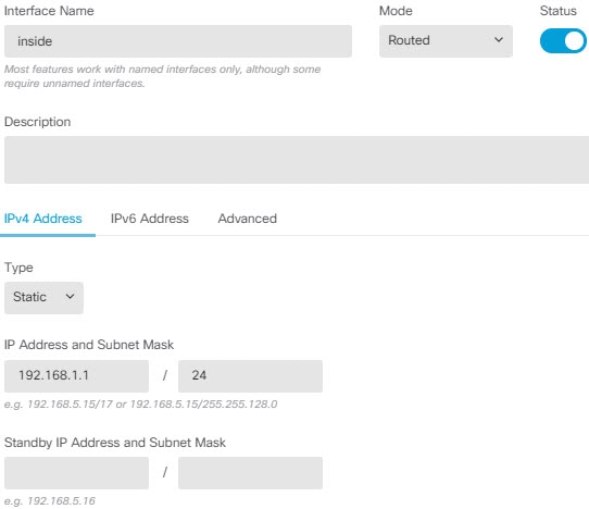
Because the routing tables are separate, you can use the same, or overlapping, address spaces across the virtual routers. For example, you could use the 192.168.1.0/24 address space for two separate virtual routers, supported by two separate physical interfaces.

Note that there are separate management and data routing tables per virtual router. For example, if you assign a management-only interface to a virtual router, then the routing table for that interface is separate from the data interfaces assigned to the virtual router.

Configuring Policies to be Virtual-Router-Aware

When you create a virtual router, the routing table for that virtual router is automatically separated from the global virtual router or any other virtual router. However, security policies are not automatically virtual-router-aware.

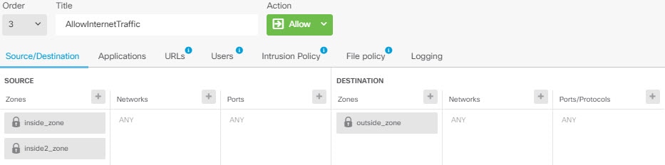
For example, if you write an access control rule that applies to “any” source or destination security zone, then the rule will apply to all interfaces across all virtual routers. This might in fact be exactly what you want. For example, all of your customers might want to block access to the same list of objectionable URL categories.

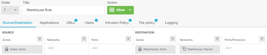
But, if you need to apply a policy to one of the virtual routers but not others, you need to create security zones that contain interfaces from that single virtual router only. Then, use the virtual-router-constrained security zones in the source and destination criteria of the security policy.

By using security zones whose memberships are constrained to the interfaces assigned to a single virtual router, you can write virtual-router-aware rules in the following policies:

  • Access control policy.

  • Intrusion and file policies.

  • SSL decryption policy.

  • Identity policy and user-to-IP address mappings. If you use overlapping address spaces in virtual routers, ensure that you create separate realms for each virtual router and apply them correctly in the identity policy rules.

If you use overlapping address spaces in your virtual routers, you should use security zones to ensure that the right policies get applied. For example, if you use the 192.168.1.0/24 address space in two separate virtual routers, an access control rule that simply specifies the 192.168.1.0/24 network will apply to traffic in both virtual routers. If that is not the desired outcome, you can limit the application of the rule by also specifying the source/destination security zones for just one of the virtual routers.

For policies that do not use security zones, such as NAT, you can write rules specific to a virtual router by selecting interfaces assigned to a single virtual router as the source and destination interfaces. If you select source and destination interfaces from two separate virtual routers, you must ensure that you have appropriate routes between the virtual routers to make the rule work.

Routing Between Virtual Routers

You can configure static routes to route traffic between virtual routers.

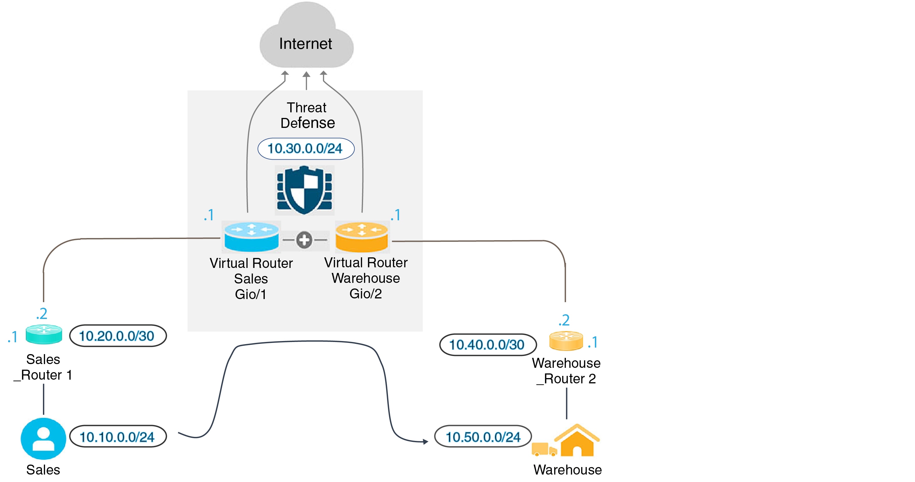
For example, if you have the outside interface in the global virtual router, you can set up static default routes in each of the other virtual routers to send traffic to the outside interface. Then, any traffic that cannot be routed within a given virtual router gets sent to the global router for subsequent routing.

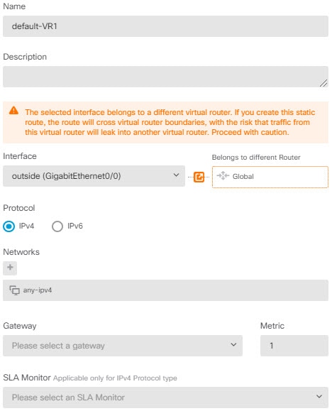
Static routes between virtual routers are known as route leaks, because you are leaking traffic to a different virtual router. When you are leaking routes, say, VR1 routes to VR2, you can initiate connections from VR2 to VR1 only. For traffic to flow from VR1 to VR2, you must configure the reverse route. When you create a static route to an interface in another virtual router, you do not need to specify a gateway address. Simply select the destination interface.

For inter-virtual-router routes, the system does destination interface look-up in the source virtual router. Then, it looks up the MAC address of the next hop in the destination virtual router. Thus, the destination virtual router must have either a dynamic (learned) or static route for the selected interface for the destination address.

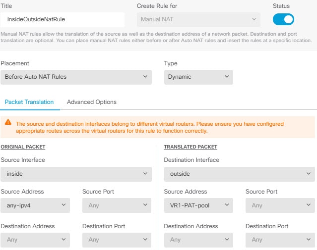
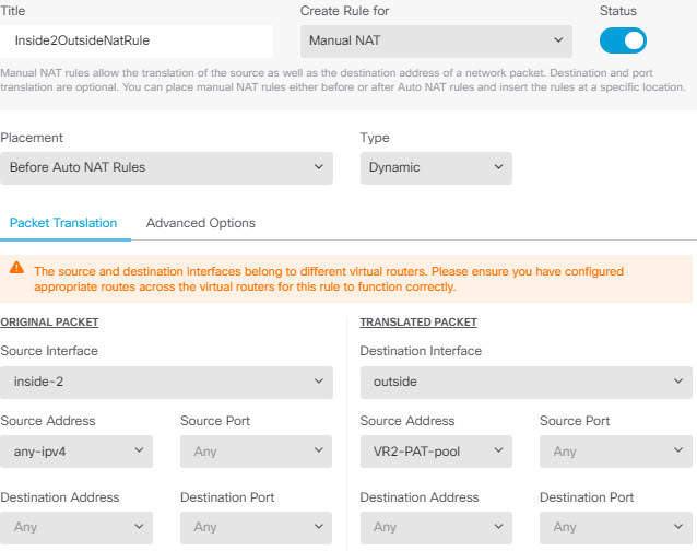
Configuring NAT rules that use source and destination interfaces in different virtual routers can also allow traffic to route between virtual routers. If you do not select the option for NAT to do a route lookup, the rule will simply send traffic out the destination interface with a NATed address whenever destination translation happens. However, the destination virtual router should have a route for the translated destination IP address so that next-hop lookup can succeed.

Maximum Number of Virtual Routers By Device Model

The maximum number of virtual routers you can create depends on the device model. The following table provides the maximum limits. You can double-check on your system by entering the show vrf counters command, which shows the maximum number of user-defined virtual routers for that platform not including the global virtual router. The numbers in the table below include user and global routers. For the Firepower 4100/9300, these numbers apply to native mode.

For platforms that support multi-instance capability, such as the Firepower 4100/9300, determine the maximum number of virtual routers per container instance by dividing the maximum virtual routers by the number of cores on the device, and then multiplying by the number of cores assigned to the instance, rounding down to the nearest whole number. For example, if the platform supports a maximum of 100 virtual routers, and it has 70 cores, then each core would support a maximum of 1.43 virtual routers (rounded). Thus, an instance assigned 6 cores would support 8.58 virtual routers, which rounds down to 8, and an instance assigned 10 cores would support 14.3 virtual routers (rounding down, 14).

Device Model

Maximum Virtual Routers

ASA 5508-X

ASA 5516-X

10

Firepower 1010

Virtual routers are not supported on this model.

Firepower 1120

5

Firepower 1140

10

Firepower 1150

10

Firepower 2110

10

Firepower 2120

20

Firepower 2130

30

Firepower 2140

40

Firepower 4110

60

Firepower 4112

60

Firepower 4115

80

Firepower 4120

80

Firepower 4125

100

Firepower 4140

100

Firepower 4145

100

Firepower 4150

100

Firepower 9300 appliance, all models

100

FTDv, all platforms

30

ISA 3000

10

Guidelines for Virtual Routers

Device Model Guidelines

You can configure virtual routers on all support device models except the following:

  • Firepower 1010

Additional Guidelines

  • You can configure the following features on the global virtual router only:

    • OSPFv3

    • RIP

    • EIGRP

    • IS-IS

    • BGPv6

    • Multicast Routing

    • Policy Based Routing

    • VPN

  • You can configure the following features separately for each virtual router:

    • Static routes and their SLA monitors.

    • OSPFv2

    • BGPv4

  • The following features are used by the system when querying or communicating with the remote system (from-the-box traffic). These features use interfaces in the global virtual router only. If you configure an interface for the feature, it must belong to the global virtual router. As a general rule, any time the system must look up a route to reach an external server for its own management purposes, it does the route lookup in the global virtual router.

    • DNS server when used to resolve fully-qualified names used in access control rules, or for resolving names for the ping command. If you specify any as the interface for a DNS server, the system considers interfaces in the global virtual router only.

    • AAA server or identity realm when used with VPN. You can configure VPN on interfaces in the global virtual router only, so the external AAA servers used for VPN, such as Active Directory, must be reachable through an interface in the global virtual router.

    • Syslog server.

    • SNMP.

  • In NAT, if you specify source and destination interfaces that are assigned to different virtual routers, the NAT rule diverts traffic from one virtual router through another virtual router. Ensure that you do not mix interfaces in NAT rules unintentionally. Normally, the source and destination interfaces are used and the routing table is ignored, including for destination translations in manual NAT. However, if the NAT rule does need to do a route lookup, it does the lookup in the VRF table for the inbound interface only. If necessary, define static routes in the source virtual router for the destination interface. Note that if you leave the interface as any, the rule applies to all interfaces regardless of virtual router membership. When using virtual routers, carefully test your NAT rules to ensure you get the expected behavior. If you neglect to define a needed route leak, in some cases the rule will not match all of the traffic you expect it to match, and the translation will not be applied.

  • If you configure inter-virtual-router routes, for example, leaking a route from one virtual router to a second virtual router, the system does destination interface look-up in the source virtual router. Then, it looks up the MAC address of the next hop in the destination virtual router. Thus, the destination virtual router must have either a dynamic (learned) or static route for the selected interface for the destination address.

  • When using inter-virtual-router routes (leaked routes), for example, from virtual router 1 to virtual router 2, you do not need to configure a mirror (reverse) route in virtual router 2 to allow return traffic. However, if you want to allow connections to be initiated in both directions, ensure that you leak the route in both directions, from virtual router 1 to 2, and from virtual router 2 to 1.

  • If you move an interface from one virtual router to another, all features configured for the interface are retained. Examine the configuration to ensure that static routes, IP addresses, and other policies make sense within the context of the new virtual router.

  • If you use overlapping address spaces in multiple virtual routers, please be aware that static security group tag (SGT) to IP address mappings downloaded from Cisco Identity Services Engine (ISE) are not virtual-router-aware. Set up separate identity realms per virtual router if you need to create different SGT mappings per virtual router. This is not necessary if you intend to map the same IP addresses to the same SGT number in each virtual router.

  • If you use overlapping address spaces in multiple virtual routers, dashboard data can be misleading. Connections for the same IP address are aggregated, so it will appear there was more traffic to/from a given address when it is shared by two or more endpoints. If you carefully construct your identity policies using separate identity realms, user-based statistics should be more accurate.

  • You cannot use overlapping DHCP address pools in separate virtual routers.

  • You can use DHCP server auto configuration on an interface in the global virtual router only. Auto configuration is not supported for interfaces assigned to a user-defined virtual router.

  • If you move an interface from one virtual router to another, including from the global virtual router to a new router, any existing connections through the interface are dropped.

  • The Security Intelligence policy is not virtual-router-aware. If you add an IP address, URL, or DNS name to the block list, it is blocked for all virtual routers.

Managing Virtual Routers

You can create multiple virtual routing and forwarding (VRF) instances, called virtual routers, to maintain separate routing tables for groups of interfaces. Because each virtual router has its own routing table, you can provide clean separation in the traffic flowing through the device.

Thus, you can provide support to two or more distinct customers over a common set of networking equipment. You can also use virtual routers to provide more separation for elements of your own network, for example, by isolating a development network from your general-purpose corporate network.

By default, virtual routing is disabled. The entire device uses a single set of global routing tables, for data (through) and management (to/from the box) traffic.

When you enable virtual routing, the initial routing page is a list of the virtual routers defined on the system. If you do not enable virtual routers, the initial routing page is a list of static routes defined on the system.

There is always a global virtual router. The global router holds all interfaces that you have not assigned to individual virtual routers.

Procedure


Step 1

Click Device, then click the link in the Routing summary.

Step 2

If you have not yet enabled virtual routers, click the Add Multiple Virtual Routers link, then click Create First Custom Virtual Router.

Creating the first virtual router is essentially the same as creating any additional virtual routers. For more information, see Create a Virtual Router or Edit Interface Assignments.

Step 3

Do any of the following:

  • To configure global BGP settings, which apply to all virtual routers, click the BGP Global Settings button. You configure these settings using Smart CLI, which is explained in Configuring Smart CLI Objects. Configure global BGP settings only if you configure BGP in one or more virtual router.

  • To create a new virtual router, click the + button above the table.

  • To edit the routing properties of a virtual router, for example, to create static routes or to define routing processes, click the view icon (View configuration button.) in the Action cell for the virtual router.

  • To edit the name, description, or interface assignments for a virtual router, click the view icon (View configuration button.) in the Action cell for the virtual router, then select the Virtual Router Properties tab.

  • To switch between virtual routers when viewing them, click the down arrow next to the virtual router name (above the routing table) and select the desired virtual router. You can return to the listing page by clicking the Go Back to Virtual Routers arrow (Go Back to Virtual Routers arrow.).

  • To delete a virtual router, click the delete icon (delete icon) in the Action cell for the virtual router, or the delete icon next to the virtual router name when viewing the virtual router’s contents. When you delete the last virtual router (other than the global router, which you cannot delete), VRF is disabled.

  • To monitor routing in a virtual router, click the link for one of the show commands in the table for that virtual router. Clicking the command opens the CLI Console, where you can examine the output of the CLI command. You can show information on routes, OSPF, and OSPF neighbors. Note that the command output is based on the deployed configuration; you will not see anything related to undeployed edits.

    You can also execute these commands by selecting them from the Commands drop-down list when viewing the virtual router.


Create a Virtual Router or Edit Interface Assignments

Before you can configure static routes or routing process on a virtual router, you must create the router and assign interfaces to it.

Before you begin

Go to the Interfaces page and ensure that each interface you want to add to the virtual router has a name. You cannot add an interface to a virtual router until it has a name.

Procedure


Step 1

Click Device > Routing.

Step 2

Do one of the following:

  • If you have not yet created a virtual router, click the Add Multiple Virtual Routers link, then click Create First Custom Virtual Router

  • Click the + button above the list of virtual routers to create a new one.

  • Click the edit icon (edit icon) for a virtual router to edit its properties and interface list.

  • When viewing a virtual router, click the Virtual Router Properties tab to edit the properties of the virtual router you are viewing.

  • When viewing a virtual router, click the down arrow next to the virtual router name and click Create New Virtual Router.

Step 3

Configure the properties of the virtual router:

  • Name—The name for the virtual router.

  • Description—An optional description of the virtual router.

  • Interfaces—Click + to select each interface that should be part of the virtual router. To remove an interface, hover over the interface and click X on the right side of the interface card. You can assign physical interfaces, subinterfaces, bridge groups, and EtherChannels to a virtual router, but not VLANs.

    The routing table will be constrained to these interfaces, unless you intentionally leak routes to other interfaces into the virtual routing table.

    You can assign the diagnostic (Management X/Y) interface to the global virtual router only.

Step 4

Click OK or Save.

You are taken to the view for this virtual router, where you can configure static routes or routing processes.


Configure Static Routes and Routing Processes in a Virtual Router

Each virtual router has its own static routes and routing processes, which operate separately from the routes and routing processes defined for any other virtual router.

When you configure static routes, you can select destination interfaces that are outside of the virtual router. This leaks the route into the virtual router that contains the destination interface. Ensure that you leak only those routes that you need to leak, to ensure that you do not send more traffic than you want to the other virtual router. For example, if you have one path to the Internet, then it makes sense to leak routes from each virtual router to the Internet-facing virtual router for traffic destined for the Internet.

Procedure


Step 1

Choose Device > Routing.

Step 2

Click the view icon (View configuration button.) in the Action cell for the virtual router to open it.

Step 3

Do any of the following:

  • To configure static routes, click the Static Routing tab, then create or edit the routes. For detailed information, see Configuring Static Routes.

  • To configure Equal-Cost Multi-Path (ECMP) traffic zones, click the ECMP Traffic Zones tab, then create the zones. For detailed information, see Configuring ECMP Traffic Zones.

  • To configure the BGP routing process, click the BGP tab, then create the Smart CLI object that is needed to define the process. For detailed information, see Border Gateway Protocol (BGP).

    There are also global settings for BGP that apply to all virtual routers. You must return to the virtual router listing page to click the BGP Global Settings button to configure these properties.

  • To configure the OSPF routing process, click the OSPF tab, then create the Smart CLI objects that are needed to define up to 2 processes, and their associated interface configurations. For detailed information, see Open Shortest Path First (OSPF).

  • (Global virtual router only.) To configure the EIGRP routing process, click the EIGRP tab, then create the Smart CLI object that is needed to define a single process. For detailed information, see Enhanced Interior Gateway Routing Protocol (EIGRP).


Delete a Virtual Router

If you no longer need a virtual router, you can delete it. You cannot delete the global virtual router.

When you delete a virtual router, you are also deleting all of the static routes, and routing processes, that are configured within the virtual router.

All interfaces assigned to the virtual router are reassigned to the global router.

Procedure


Step 1

Choose Device > Routing.

Step 2

Do one of the following:

  • In the list of virtual routers, click the delete icon (delete icon) in the Action column for the virtual router.

  • When viewing the virtual router you want to delete, click the delete icon (delete icon) next to the router’s name.

You are prompted to confirm that you want to delete the virtual router.

Step 3

Click OK to confirm the deletion.


Examples for Virtual Routers

The following topics provide examples of implementing virtual routers.

How to Route to a Distant Server through Multiple Virtual Routers

When you use virtual routers, you might have a situation where users in one virtual router need access to a server that is reachable only through a separate virtual router.

Consider the following illustration. The sales team’s workstations are connected to the Sales virtual router. The warehouse servers are connected through the Warehouse virtual router. If the sales team needs to look up information on the warehouse server whose IP address is 10.50.0.5/24, you need to leak a route from the Sales virtual router into the Warehouse virtual router. The Warehouse virtual router must also have a route to the warehouse server, which is multiple hops away behind Warehouse Router 2.


Network diagram for the route leak example.

Before you begin

This example assumes that you have already configured:

  • Both the Sales and Warehouse virtual routers on the FTD device, with GigabitEthernet 0/1 assigned to Sales, and GigabitEthernet 0/2 assigned to Warehouse.

  • The Sales Router 1 has either a static or dynamic route that will send traffic to 10.50.0.5/24 out the 10.20.0.1/30 interface.

Procedure


Step 1

Create the network object for 10.50.0.5/24 or 10.50.0.0/24. Also, create the object for the gateway, 10.40.0.2/30.

If you want to limit the route to the single IP address of the warehouse server, use a host object to define 10.50.0.5. Alternatively, if the sales team should have access to other systems in the warehouse, create a network object for the 10.50.0.0/24 network. In this example, we will create a route for the host IP address.

  1. Choose Objects, then Networks from the table of contents.

  2. Click +, then fill in the object properties for the warehouse server:


    Warehouse server network object.

  3. Click OK.

  4. Click +, then fill in the object properties for the router gateway to the warehouse network:


    Warehouse gateway network object.

  5. Click OK.

Step 2

Define the route leak in Sales that points to the Gi0/2 interface in the Warehouse virtual router.

In this example, Gi0/1 is named inside, and Gi0/2 is named inside-2.

  1. Choose Device, then click View Configuration in the Routing summary.

  2. In the list of virtual routers, click the view icon (View configuration button.) in the action column for the Sales virtual router.

  3. On the Static Routing tab, click + and configure the route:

    • Name—Any name will do, such as Warehouse-server-route.

    • Interface—Select inside-2. You will see a warning saying that the interface is in a different router and you are creating a route leak. This is what you want to do.

    • Protocol—For this example, use IPv4. You can alternatively use IPv6 addresses to implement this example.

    • Networks—Select the Warehouse-Server object.

    • Gateway—Leave this item blank. When leaking a route into another virtual router, you do not select the gateway address.

    The dialog box should look similar to the following:


    Route leak for the warehouse server.

  4. Click OK.

Step 3

In the Warehouse virtual router, define the route that points to the Warehouse Router 2 gateway.

Alternatively, this can be done by configuring a routing protocol that would dynamically discover the route from Warehouse Router 2. For this example, we will define the static route.

  1. From the virtual router drop-down that currently says Sales, select the Warehouse virtual router to switch routers.


    Switching virtual routers.

  2. On the Static Routing tab, click + and configure the route:

    • Name—Any name will do, such as Warehouse-route.

    • Interface—Select inside-2.

    • Protocol—Select IPv4.

    • Networks—Select the Warehouse-Server object.

    • Gateway—Select the Warehouse-gateway object.

    The dialog box should look similar to the following:


    Static route to the warehouse server.

  3. Click OK.

Step 4

Ensure that there is an access control rule that allows access to the warehouse server.

The simplest rule would allow traffic from the source interfaces in the Sales virtual router to the destination interfaces in the Warehouse virtual router for the destination Warehouse-Server network object. You can apply intrusion inspection to the traffic as you see fit.

For example, if the interfaces in Sales are in the Sales-Zone security zone, and those in Warehouse are in the Warehouse-Zone security zone, the access control rule would look similar to the following:


Access control rule to allow traffic to the warehouse server.


How to Provide Internet Access to Multiple Virtual Routers with Overlapping Address Spaces

When using virtual routers, you can have the same network address for interfaces that reside in separate routers. For example, you could define interfaces inside and inside-2 to both use the IP address 192.168.1.1/24, managing endpoints on their segment in the 192.168.1.0/24 network. However, because the IP addresses routed in these separate virtual routers are the same, you need to carefully handle traffic that leaves the virtual routers, to ensure that return traffic goes to the correct destination.

For example, to allow Internet access from two virtual routers that use the same address space, you need to apply NAT rules separately to the interfaces within each virtual router, ideally using separate NAT or PAT pools. You could use PAT to translate the source addresses in virtual router 1 to 10.100.10.1, and for those in virtual router 2, to 10.100.10.2. The following illustration shows this setup, where the Internet-facing outside interface is part of the global router. Note that you must define the NAT/PAT rules with the source interface explicitly selected, because using “any” as the source interface will make it impossible for the system to identify the correct source because the same IP address could exist on 2 different interfaces.


Network diagram for overlapping address space.


Note


This example is simplified, where each virtual router contains a single interface. If an “inside” virtual router has more than one interface, you need to create the NAT rules for each “inside” interface. Even if you have some interfaces within virtual routers that do not use overlapping address spaces, explicitly identifying the source interface in NAT rules might make troubleshooting easier, and ensure a cleaner separation between traffic from the virtual routers that is Internet-bound.


Procedure


Step 1

Configure the inside interface for virtual router 1 (VR1).

  1. Click Device, then View All Interfaces in the Interface summary.

  2. Click the edit icon (edit icon) in the Action column for the interface you will assign to VR1.

  3. Configure at least the following properties:

    • Name—For this example, inside.

    • Mode—Select Routed.

    • Status—Enable the interface.

    • IPv4 Address > Type—Select Static.

    • IPv4 Address and Subnet Mask—Enter 192.168.1.1/24.


    Properties for the inside interface.

  4. Click OK.

Step 2

Configure the inside-2 interface for virtual router 2 (VR2), but do not specify the IP address.

  1. On the Interfaces listing page, click the edit icon (edit icon) in the Action column for the interface you will assign to VR2.

  2. Configure at least the following properties:

    • Name—For this example, inside-2.

    • Mode—Select Routed.

    • Status—Enable the interface.

    • IPv4 Address > Type—Select Static.

    • IPv4 Address and Subnet Mask—Leave these fields empty. If you try to configure the same address as the inside interface at this point, the system will show an error message and prevent you from creating a non-functional configuration. You cannot route to the same address space through different interfaces within the same router.


    Properties of the inside-2 interface.

  3. Click OK.

Step 3

Configure virtual router VR1, including the static default route leak to the outside interface.

  1. Choose Device, then click View Configuration in the Routing summary.

  2. Click Add Multiple Virtual Routers at the top of the Routing page.

  3. At the bottom right of the explanatory panel, click Create First Custom Virtual Router.

  4. Fill in the properties for virtual router VR1.

    • Name—Enter VR1 or another name of your choosing.

    • Interfaces—Click +, select inside, and click OK.


    Properties of virtual router 1, VR1.

  5. Click OK.

    The dialog box closes, and you are shown the list of virtual routers.

  6. In the list of virtual routers, click the view icon (View configuration button.) in the action column for the VR1 virtual router.

  7. On the Static Routing tab, click + and configure the route:

    • Name—Any name will do, such as default-VR1.

    • Interface—Select outside. You will see a warning saying that the interface is in a different router and you are creating a route leak. This is what you want to do.

    • Protocol—For this example, use IPv4.

    • Networks—Select the any-ipv4 object. This will be the default route for any traffic that cannot be routed within VR1.

    • Gateway—Leave this item blank. When leaking a route into another virtual router, you do not select the gateway address.

    The dialog box should look similar to the following:


    Static route leak from VR1 to the Global virtual router.

  8. Click OK.

Step 4

Configure virtual router VR2, including the static default route leak to the outside interface.

  1. When viewing VR1, click the back button (Go Back to Virtual Routers arrow.) to return to the list of virtual routers.

  2. Click + at the top of the list.

  3. Fill in the properties for virtual router VR2.

    • Name—Enter VR2 or another name of your choosing.

    • Interfaces—Click +, select inside-2, and click OK.


    Properties of virtual router 2, VR2.

  4. Click OK.

    The dialog box closes, and you are shown the list of virtual routers.

  5. In the list of virtual routers, click the view icon (View configuration button.) in the action column for the VR2 virtual router.

  6. On the Static Routing tab, click + and configure the route:

    • Name—Any name will do, such as default-VR2.

    • Interface—Select outside. You will see a warning saying that the interface is in a different router and you are creating a route leak. This is what you want to do.

    • Protocol—For this example, use IPv4.

    • Networks—Select the any-ipv4 object. This will be the default route for any traffic that cannot be routed within VR2.

    • Gateway—Leave this item blank. When leaking a route into another virtual router, you do not select the gateway address.

    The dialog box should look similar to the following:


    Static route leak from VR2 to the Global virtual router.

  7. Click OK.

Step 5

Create the default route in global router to the outside interface.

The purpose of this route is to assign the right gateway to traffic leaked from the two virtual routers to the outside interface in the global router.

  1. When viewing VR2, click the VR2 name at the top of the page to open the list of virtual routers, and select the Global router.


    Switching to the Global virtual router.

  2. On the Static Routing tab for the Global router, click + and configure the route:

    • Name—Any name will do, such as default-ipv4.

    • Interface—Select outside.

    • Protocol—For this example, use IPv4.

    • Networks—Select the any-ipv4 object. This will be the default route for any IPv4 traffic.

    • Gateway—Assuming the object does not already exist, click Create New Network Object, then define a host object for the IP address of the gateway at the other end of the network link on the outside interface, in this case, 172.16.1.2. After you create the object, select it in the Gateway field of the static route.


      Network object for the gateway address.

    The dialog box should look similar to the following:


    Default route in the Global virtual router.

  3. Click OK.

Step 6

Go back to the Interfaces page and add the IP address to inside-2.

  1. Click Device, then View All Interfaces in the Interface summary.

  2. Click the edit icon (edit icon) in the Action column for the inside-2 interface that you assigned to VR2.

  3. On the IPv4 Address tab, enter 192.168.1.1/24 as the IP address and subnet mask.

  4. Click OK.

    You do not get an error for a duplicate IP address this time because the inside and inside-2 interfaces are now in separate virtual routers.

Step 7

Create the NAT rule to PAT inside to outside traffic to 10.100.10.1.

  1. Choose Policies, then click NAT.

  2. If there is already a manual NAT rule named InsideOutsideNatRule for the inside to outside interface, applying interface PAT, click the edit icon (edit icon) for the rule. Otherwise, click + to create a new rule.

    If you edit an existing rule, note that there is now a warning that the source and destination interfaces are in different virtual routers and you need to define routes. This is what you did earlier in the procedure.

  3. Assuming you are editing an existing rule, click the drop-down arrow in Translated Packet > Source Address, and click Create New Network (assuming you do not already have a host object defining 10.100.10.1).

  4. Configure the host network object for the PAT address. The object should be similar to the following:


    PAT pool for VR1.

  5. Select the new object as the Translated Packet > Source Address. The NAT rule should look similar to the following:


    NAT rule to perform PAT on VR1 traffic.

  6. Click OK.

Step 8

Create the NAT rule to PAT inside-2 to outside traffic to 10.100.10.2.

This rule will look exactly like the rule for VR1, with these exceptions:

  • Name—This must be unique, for example, Inside2OutsideNatRule.

  • Original Packet > Source Interface—Select inside-2.

  • Translated Packet > Source Address—Create a new host network object for 10.100.10.2.

The rule should look similar to the following:


NAT rule to perform PAT on VR2 traffic.

Step 9

Choose Policies > Access Control, and configure an access control rule to allow traffic from inside_zone and inside2_zone to outside_zone.

Finally, you need to configure the access control policy to allow traffic from the inside and inside-2 interfaces to the outside interface. Because the access control rule requires the use of security zones, you need to create zones for each of these interfaces. Alternatively, you could create a single zone to hold both inside and inside-2, but it is likely that you will want to create additional rules, here or in other policies, that differentiate how traffic is treated in these routers.

Assuming that you create zones named after the interfaces, a basic rule that allows all traffic to flow to the Internet will look like the following. You can apply an intrusion policy to this rule as you see fit. You can define additional rules to block unwanted traffic, for example, to implement URL filtering.


Access control rule to allow VR1 and VR2 traffic to the Internet.


Monitoring Virtual Routers

To monitor and troubleshoot virtual routers, open the CLI console or log into the device CLI and use the following commands. You can also select some of these commands from the Commands menu on the Routing page.

  • show vrf displays information about the virtual routers defined on the system.

  • show ospf [ vrf name | all]

    Displays information about the OSPF process in a virtual router. You can specify a virtual router to see information about the process in that virtual router only, or omit the option so see information about VRF across all virtual routers. Use show ospf ? to see additional options.

  • show bgp [ vrf name | all]

    Displays information about the BGP process in a virtual router. You can specify a virtual router to see information about the process in that virtual router only, or omit the option so see information about VRF across all virtual routers. Use show bgp ? to see additional options.

  • show eigrp option

    Displays information about the EIGRP process. Use show eigrp ? to see the available options.