About Virtual Routers and Virtual Routing and Forwarding (VRF)
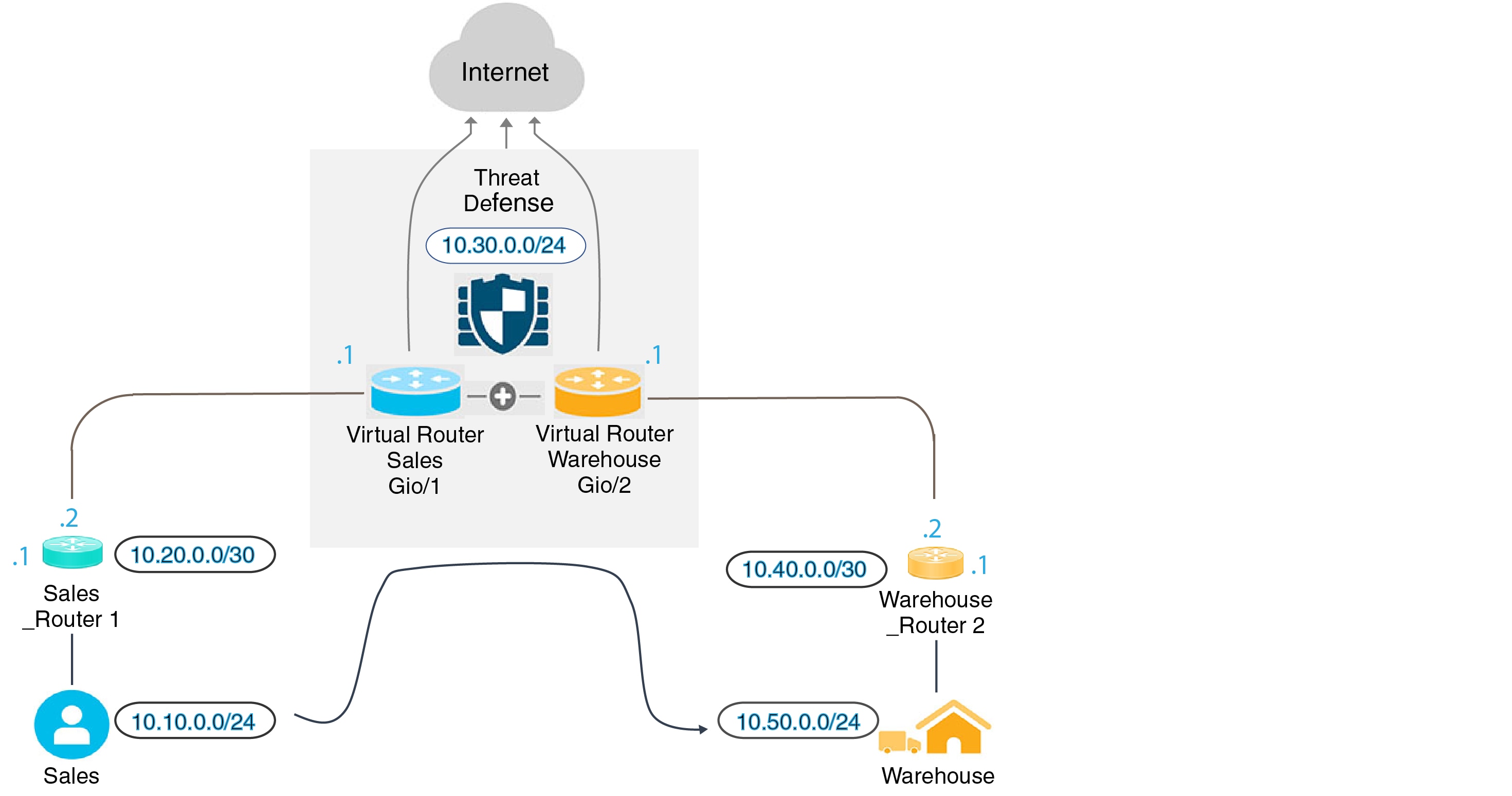
You can create multiple virtual routers to maintain separate routing tables for groups of interfaces. Because each virtual router has its own routing table, you can provide clean separation in the traffic flowing through the device.
Thus, you can provide support to two or more distinct customers over a common set of networking equipment. You can also use virtual routers to provide more separation for elements of your own network, for example, by isolating a development network from your general purpose corporate network.
Virtual routers implement the “light” version of Virtual Routing and Forwarding, or VRF-Lite, which does not support Multiprotocol Extensions for BGP (MBGP).
When you create a virtual router, you assign interfaces to the router. You can assign a given interface to one, and only one, virtual router. You would then define static routes, and configure routing protocols such as OSPF or BGP, for each virtual router. You would also configure separate routing processes over your entire network, so that routing tables on all participating devices are using the same per-virtual-router routing process and tables. Using virtual routers, you create logically-separated networks over the same physical network to ensure the privacy of the traffic that runs through each virtual router.
Because the routing tables are separate, you can use the same, or overlapping, address spaces across the virtual routers. For example, you could use the 192.168.1.0/24 address space for two separate virtual routers, supported by two separate physical interfaces.
Note that there are separate management and data routing tables per virtual router. For example, if you assign a management-only interface to a virtual router, then the routing table for that interface is separate from the data interfaces assigned to the virtual router.
Configuring Policies to be Virtual-Router-Aware
When you create a virtual router, the routing table for that virtual router is automatically separated from the global virtual router or any other virtual router. However, security policies are not automatically virtual-router-aware.
For example, if you write an access control rule that applies to “any” source or destination security zone, then the rule will apply to all interfaces across all virtual routers. This might in fact be exactly what you want. For example, all of your customers might want to block access to the same list of objectionable URL categories.
But, if you need to apply a policy to one of the virtual routers but not others, you need to create security zones that contain interfaces from that single virtual router only. Then, use the virtual-router-constrained security zones in the source and destination criteria of the security policy.
By using security zones whose memberships are constrained to the interfaces assigned to a single virtual router, you can write virtual-router-aware rules in the following policies:
-
Access control policy.
-
Intrusion and file policies.
-
SSL decryption policy.
-
Identity policy and user-to-IP address mappings. If you use overlapping address spaces in virtual routers, ensure that you create separate realms for each virtual router and apply them correctly in the identity policy rules.
If you use overlapping address spaces in your virtual routers, you should use security zones to ensure that the right policies get applied. For example, if you use the 192.168.1.0/24 address space in two separate virtual routers, an access control rule that simply specifies the 192.168.1.0/24 network will apply to traffic in both virtual routers. If that is not the desired outcome, you can limit the application of the rule by also specifying the source/destination security zones for just one of the virtual routers.
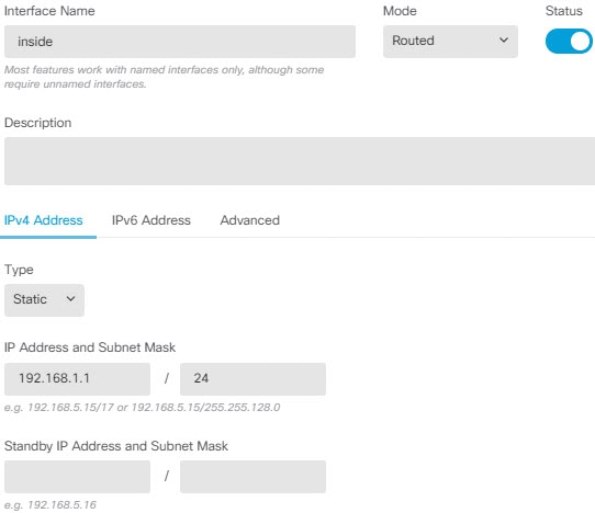
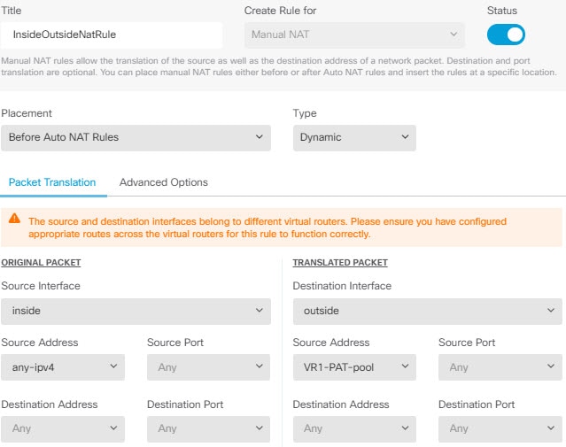
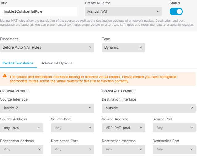
For policies that do not use security zones, such as NAT, you can write rules specific to a virtual router by selecting interfaces assigned to a single virtual router as the source and destination interfaces. If you select source and destination interfaces from two separate virtual routers, you must ensure that you have appropriate routes between the virtual routers to make the rule work.
Routing Between Virtual Routers
You can configure static routes to route traffic between virtual routers.
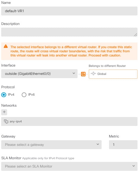
For example, if you have the outside interface in the global virtual router, you can set up static default routes in each of the other virtual routers to send traffic to the outside interface. Then, any traffic that cannot be routed within a given virtual router gets sent to the global router for subsequent routing.
Static routes between virtual routers are known as route leaks, because you are leaking traffic to a different virtual router. When you are leaking routes, say, VR1 routes to VR2, you can initiate connections from VR2 to VR1 only. For traffic to flow from VR1 to VR2, you must configure the reverse route. When you create a static route to an interface in another virtual router, you do not need to specify a gateway address. Simply select the destination interface.
For inter-virtual-router routes, the system does destination interface look-up in the source virtual router. Then, it looks up the MAC address of the next hop in the destination virtual router. Thus, the destination virtual router must have either a dynamic (learned) or static route for the selected interface for the destination address.
Configuring NAT rules that use source and destination interfaces in different virtual routers can also allow traffic to route between virtual routers. If you do not select the option for NAT to do a route lookup, the rule will simply send traffic out the destination interface with a NATed address whenever destination translation happens. However, the destination virtual router should have a route for the translated destination IP address so that next-hop lookup can succeed.
Maximum Number of Virtual Routers By Device Model
The maximum number of virtual routers you can create depends on the device model. The following table provides the maximum limits. You can double-check on your system by entering the show vrf counters command, which shows the maximum number of user-defined virtual routers for that platform not including the global virtual router. The numbers in the table below include user and global routers. For the Firepower 4100/9300, these numbers apply to native mode.
For platforms that support multi-instance capability, such as the Firepower 4100/9300, determine the maximum number of virtual routers per container instance by dividing the maximum virtual routers by the number of cores on the device, and then multiplying by the number of cores assigned to the instance, rounding down to the nearest whole number. For example, if the platform supports a maximum of 100 virtual routers, and it has 70 cores, then each core would support a maximum of 1.43 virtual routers (rounded). Thus, an instance assigned 6 cores would support 8.58 virtual routers, which rounds down to 8, and an instance assigned 10 cores would support 14.3 virtual routers (rounding down, 14).
|
Device Model |
Maximum Virtual Routers |
|---|---|
|
Firepower 1010 |
Virtual routers are not supported on this model. |
|
Firepower 1120 |
5 |
|
Firepower 1140 |
10 |
|
Firepower 1150 |
10 |
|
Firepower 2110 |
10 |
|
Firepower 2120 |
20 |
|
Firepower 2130 |
30 |
|
Firepower 2140 |
40 |
|
Secure Firewall 3110 |
15 |
|
Secure Firewall 3120 |
25 |
|
Secure Firewall 3130 |
50 |
|
Secure Firewall 3140 |
100 |
|
Firepower 4110 |
60 |
|
Firepower 4112 |
60 |
|
Firepower 4115 |
80 |
|
Firepower 4120 |
80 |
|
Firepower 4125 |
100 |
|
Firepower 4140 |
100 |
|
Firepower 4145 |
100 |
|
Firepower 4150 |
100 |
|
Firepower 9300 appliance, all models |
100 |
|
Threat Defense Virtual, all platforms |
30 |
|
ISA 3000 |
10 |









 Feedback