Installation, Maintenance, and Upgrade

Remove and Replace the Supervisor

You can remove the Firepower 9300 Supervisor while the system is powered on without damage to the Supervisor hardware or system. However, because the supervisor is controlling the entire chassis, including the power system, we recommend that you use the power switch on the rear panel of the chassis to put the system in standby mode. See Supervisor for more information about the Supervisor.

Safety Warnings

Take note of the following component replacement safety warnings:


Warning


Statement 1028—More Than One Power Supply

This unit might have more than one power supply connection. To reduce risk of electric shock, remove all connections to de-energize the unit.


Warning


Statement 1073—No User-Serviceable Parts

There are no serviceable parts inside. To avoid risk of electric shock, do not open.


Warning


Statement 1089—Instructed and Skilled Person Definitions

An instructed person is someone who has been instructed and trained by a skilled person and takes the necessary precautions when working with equipment.

A skilled person or qualified personnel is someone who has training or experience in the equipment technology and understands potential hazards when working with equipment.

There are no serviceable parts inside. To avoid risk of electric shock, do not open.


Warning


Statement 1090—Installation by Skilled Person

Only a skilled person should be allowed to install, replace, or service this equipment. See statement 1089 for the definition of a skilled person.

There are no serviceable parts inside. To avoid risk of electric shock, do not open.


Warning


Statement 1091—Installation by an Instructed Person

Only an instructed person or skilled person should be allowed to install, replace, or service this equipment. See statement 1089 for the definition of an instructed or skilled person.

There are no serviceable parts inside. To avoid risk of electric shock, do not open.


Procedure


Step 1

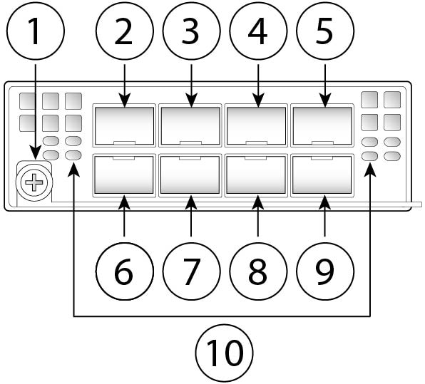
To remove the Supervisor, loosen the two captive screws on the Supervisor tray.

Step 2

Remove the Supervisor tray from the chassis by pulling the handle on the Supervisor until it is unseated.

Step 3

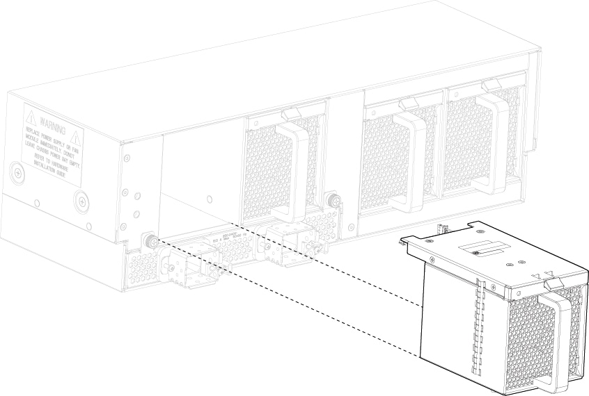
Slide the tray partway out of the chassis, place your other hand under the tray to support its weight, and remove it from the chassis.

Figure 1. Remove and Replace the Supervisor

Step 4

To install a new Supervisor tray, grasp the front of the tray and place your other hand under the tray to support it.

Step 5

Open the handle on the front of the tray.

Step 6

Gently slide the tray into the opening until you cannot push it any farther.

Step 7

Press the handle so that it catches the edge of the chassis and presses the tray all the way in.

Step 8

When the tray is all the way in the chassis, push in the handle to fully seat the tray.

Step 9

Using your fingers, tighten the captive screw on the front of the Supervisor; if using a screw driver, tighten to no more than 3 in-lbs.

Tightening the captive screws with your fingers is unlikely to lead to stripped or damaged captive screws.

Install, Remove, and Replace the Security Module

This procedure describes how to install a security module into an empty slot that has never contained a security module, and how to remove an installed security module and replace it with another security module.

You can remove the Firepower 9300 security module while the system is running, but we recommend that you use the power switch on the rear of the chassis to put the security module in standby mode before removal and reinstallation. If you install a new service module in an empty slot, you do not need to power off the system.


Note


Make sure you have the correct firmware package and software version installed to support your security module. For instructions on how to verify your firmware package version and to upgrade the firmware if necessary, see the Cisco Firepower 4100/9300 FXOS Firmware Upgrade Guide. See Cisco Firepower 4100/9300 FXOS Compatibility for the software compatibility matrix.


Caution


If you want to replace an existing security module with another security module, you must decommission the old security module before removing it. See the "Security Module/Engine Management" chapter in the Cisco FXOS Firepower Chassis Manager Configuration Guide for the instructions. After you decommission the old security module, you can remove it, install the new security module, have the system acknowledge it, and then reinitialize it.


Safety Warnings

Take note of the following component replacement safety warnings:


Warning


Statement 1028—More Than One Power Supply

This unit might have more than one power supply connection. To reduce risk of electric shock, remove all connections to de-energize the unit.


Warning


Statement 1073—No User-Serviceable Parts

There are no serviceable parts inside. To avoid risk of electric shock, do not open.


Warning


Statement 1089—Instructed and Skilled Person Definitions

An instructed person is someone who has been instructed and trained by a skilled person and takes the necessary precautions when working with equipment.

A skilled person or qualified personnel is someone who has training or experience in the equipment technology and understands potential hazards when working with equipment.

There are no serviceable parts inside. To avoid risk of electric shock, do not open.


Warning


Statement 1090—Installation by Skilled Person

Only a skilled person should be allowed to install, replace, or service this equipment. See statement 1089 for the definition of a skilled person.

There are no serviceable parts inside. To avoid risk of electric shock, do not open.


Warning


Statement 1091—Installation by an Instructed Person

Only an instructed person or skilled person should be allowed to install, replace, or service this equipment. See statement 1089 for the definition of an instructed or skilled person.

There are no serviceable parts inside. To avoid risk of electric shock, do not open.


Procedure


Step 1

To install a new security module for the first time into an empty slot, do the following:

  1. Follow steps 6 through 10.

  2. Enter scope slot > acknowledge to bring the new security module online.

Step 2

To remove a security module, loosen the captive screw on the front of the security module.

Step 3

Remove the security module from the chassis by pulling the handle on the security module until it is unseated.

Step 4

Slide the security module partway out of the chassis, place your other hand under the security module to support its weight, and remove it from the chassis.

Figure 2. Remove and Install the Security Module

Step 5

Place the security module on an antistatic mat or antistatic foam if you are not immediately reinstalling it in another slot.

If the slot is to remain empty, install a blank faceplate to ensure proper airflow and to keep dust out of the chassis; otherwise install another security module.

Step 6

To install a new security module, grasp the front of the security module and place your other hand under the security module to support it.

Step 7

Open the handle in the front of the security module.

Step 8

Gently slide the security module into the opening until you cannot push it any farther.

Step 9

Press the handle so that it catches the edge of the chassis and presses the security module all the way in.

Step 10

Using your fingers, tighten the captive screw on the front of the security module; if using a screw driver, tighten to no more than 3 in-lbs.

Tightening the captive screws with your fingers is unlikely to lead to stripped or damaged captive screws.

Remove and Replace the SSD

There are two SSDs in each security module. They are configured in a RAID 1 configuration. If one or both SSDs fail, you must decommission the security module and acknowledge the slot to start the SSD installation and update the inventory. See the "Security Module/Engine Management" chapter in the Cisco FXOS Firepower Chassis Manager Configuration Guide for the instructions. After you decommission the security module, you can remove the SSDs, install the new SSDs, and acknowledge the slot to bring the security module back online.


Note


Once you replace the SSD, the storage controller rebuilds the newly installed SSD and no loss of data should occur. If both SSDs fail, no data can be recovered.


Note


The two SSDs in RAID 1 store each other's data. Breaking the RAID pair to use in another service module causes the service module to fail discovery by the Supervisor.


Safety Warnings

Take note of the following warnings:


Warning


Statement 1028—More Than One Power Supply

This unit might have more than one power supply connection. To reduce risk of electric shock, remove all connections to de-energize the unit.


Warning


Statement 1073—No User-Serviceable Parts

There are no serviceable parts inside. To avoid risk of electric shock, do not open.


Warning


Statement 1089—Instructed and Skilled Person Definitions

An instructed person is someone who has been instructed and trained by a skilled person and takes the necessary precautions when working with equipment.

A skilled person or qualified personnel is someone who has training or experience in the equipment technology and understands potential hazards when working with equipment.

There are no serviceable parts inside. To avoid risk of electric shock, do not open.


Warning


Statement 1090—Installation by Skilled Person

Only a skilled person should be allowed to install, replace, or service this equipment. See statement 1089 for the definition of a skilled person.

There are no serviceable parts inside. To avoid risk of electric shock, do not open.


Warning


Statement 1091—Installation by an Instructed Person

Only an instructed person or skilled person should be allowed to install, replace, or service this equipment. See statement 1089 for the definition of an instructed or skilled person.

There are no serviceable parts inside. To avoid risk of electric shock, do not open.


Procedure


Step 1

Decommission the security module.

Step 2

To remove an SSD, face the front of the chassis, press the handle release on the SSD and gently pull it out of the slot.

Figure 3. Remove the SSD

1

Handle

2

Handle release

Step 3

To replace the SSD, hold the SSD in front of slot 1, push it in gently until it is seated, and close the handle.

Step 4

Tighten the captive screws on either side of the SSD.

Step 5

Acknowledge the slot to start the SSD installation.


Install, Remove, and Replace the Single-Wide Network Module

This procedure describes how to install a network module into an empty slot that has never contained a network module, and how to remove an installed network module and replace it with another network module.

Hot Swapping

Verify that you have the correct software to support hot swapping on the Firepower 10-Gb and 40-Gb nonhardware bypass network modules. See Cisco Firepower 4100/9300 FXOS Compatibility for the software compatibility matrix. You must hot swap with an identical network module, that is, a network module with the same PID. See Product ID Numbers for a list of the network module PIDs. You must bring the network module offline using the appropriate CLI commands before removing the network module from the chassis so that all network module configuration is saved.


Caution


We do not recommend that you remove the network module without bringing it properly offline using the appropriate CLI commands.


Note


Verify that you have the correct ROMMON on the Supervisor to support hot swapping. For instructions on how to verify your firmware package version and to upgrade the firmware if necessary, see the Cisco Firepower 4100/9300 FXOS Firmware Upgrade Guide.


To remove and replace the network modules that do not currently support hot swapping, power off the chassis, replace the network module, and then power the chassis back on.


Note


Verify that you have the correct ROMMON on the Supervisor to support the 100-Gb network modules (FPR9K-NM-4X100G and FPR9K-NM-2X100G). For instructions on how to verify your firmware package version and to upgrade the firmware if necessary, see the Cisco Firepower 4100/9300 FXOS Firmware Upgrade Guide.


The following figure shows the front panel of the 10-Gb nonhardware bypass network module. The location of the captive screw, ports, and LEDs is shown. See Network Modules for more information about the other single-wide network modules.

Figure 4. Firepower Network Module 10 Gb

1

Captive screw/handle

2

Ethernet X/1

3

Ethernet X/3

4

Ethernet X/5

5

Ethernet X/7

6

Ethernet X/2

7

Ethernet X/4

8

Ethernet X/6

9

Ethernet X/8

10

Network activity LEDs

  • Off—No connection or port is not in use.

  • Amber—No link or network failure.

  • Green—Link up.

  • Green, flashing—Network activity.

Safety Warnings

Take note of the following component replacement safety warnings:


Warning


Statement 1028—More Than One Power Supply

This unit might have more than one power supply connection. To reduce risk of electric shock, remove all connections to de-energize the unit.


Warning


Statement 1073—No User-Serviceable Parts

There are no serviceable parts inside. To avoid risk of electric shock, do not open.


Warning


Statement 1089—Instructed and Skilled Person Definitions

An instructed person is someone who has been instructed and trained by a skilled person and takes the necessary precautions when working with equipment.

A skilled person or qualified personnel is someone who has training or experience in the equipment technology and understands potential hazards when working with equipment.

There are no serviceable parts inside. To avoid risk of electric shock, do not open.


Warning


Statement 1090—Installation by Skilled Person

Only a skilled person should be allowed to install, replace, or service this equipment. See statement 1089 for the definition of a skilled person.

There are no serviceable parts inside. To avoid risk of electric shock, do not open.


Warning


Statement 1091—Installation by an Instructed Person

Only an instructed person or skilled person should be allowed to install, replace, or service this equipment. See statement 1089 for the definition of an instructed or skilled person.

There are no serviceable parts inside. To avoid risk of electric shock, do not open.


Procedure


Step 1

To install a new network module for the first time into an empty slot, do the following:

  1. Power down the chassis by moving the power switch to the OFF position.

  2. Follow Steps 5 through 7 to install the new network module.

  3. Power on the chassis by moving the power switch to the ON position.

    The state for the new network module is OIR Failed.

  4. To change the status of the network module to Online, reboot the chassis. See the "Rebooting the Firepower 4100/9300 Chassis" topic in the System Administration chapter in the FXOS Configuration Guide for your software version.

Step 2

To remove and replace an existing network module, do one of the following:

  1. Save your configuration.

  2. Power down the chassis by moving the power switch to the OFF position (if removing a network module that does not support hot swapping).

  3. Bring the network module offline using the appropriate CLI command (if removing a network module that supports hot swapping). All network module configuration is saved. See the “Taking a Network Module Offline or Online” topic in the Security Module/Engine Management chapter in the FXOS Configuration Guide for your software version.

  4. Continue with Step 3.

Step 3

To remove the network module, loosen the captive screw on the left of the network module, release the handle until it is fully rotated, and then gently pull the network module out of the chassis.

Figure 5. Remove and Replace the Single-Wide Network Module
If the slot is to remain empty, install a blank faceplate to ensure proper airflow and to keep dust out of the chassis; otherwise, install another network module.

Step 4

(Optional) If you are installing a single-wide network module into a double-wide slot, you must install a divider. The blank faceplates are for a single slot, so install the divider if you are covering two single network slots.

Note


The original 9300 chassis and the newer 9300 chassis have different dividers. You can order FPR9K-NM-DIV=, which contains a screw and both dividers in case you have lost the divider (part number 800-101936-01) for the older chassis or you need the new divider (part number 700-112465-01) for the newer chassis.

Step 5

To install a new network module, hold the network module in front of the network module slot on the right side of the chassis with the handle fully extended. Slowly push the module into the network module slot until the handle catches on the mating feature in the chassis. The handle should engage correctly.

Step 6

Gently push on the handle until it is fully seated on the network module faceplate and the module is fully seated in the chassis.

Step 7

Tighten the captive screw on the left of the network module.

Step 8

Do one of the following:

  1. Power up the chassis so that the new network module is recognized (if the new network module does not support hot swapping).

  2. Bring the new network module online using the appropriate CLI command (if the new network module supports hot swapping). The saved network module configuration is automatically reapplied when the network module is back online.

    Note


    If you install a network module that is a different PID than the original network module, the saved configuration is deleted and the default configuration is applied. You must enter the acknowledge command to confirm the network module PID change.

    Follow the procedures in the FXOS Configuration Guide to connect to the network module and make sure that it has been discovered correctly by the Firepower 9300.


Install, Remove, and Replace the Double-Wide Network Module

This procedure describes how to install a network module into an empty slot that has never contained a network module, and how to remove an installed network module and replace it with another network module.


Note


Make sure your Firepower 9300 has the correct firmware package installed before you install the Firepower 100-Gb network module. For instructions on how to verify your firmware package version and to upgrade the firmware if necessary, see the Cisco Firepower 4100/9300 FXOS Firmware Upgrade Guide.


The Firepower 100-Gb network module is an optional, removable I/O module that provides two fiber 100 Gigabit Ethernet interfaces. It takes up two slots in the Firepower 9300 and supports single and multimode.

Verify that your software supports hot swapping. See Cisco Firepower 4100/9300 FXOS Compatibility for the software compatibility matrix. After removing and replacing the network module, you must reboot the system so that the Firepower 9300 discovers the new network module. See Network Modules for more information about Firepower 9300 network modules.

The following figure shows the front panel view of the Firepower 9300 100-Gb network module.

Figure 6. 100-Gb Network Module

1

Captive screw on handle

2

100-Gigabit Ethernet QSFP28 fiber port

Ethernet X/1

3

100-Gigabit Ethernet QSFP28 fiber port

Ethernet X/2

4

Network activity LEDs

  • Off—No connection or port is not in use.

  • Amber—No link or network failure.

  • Green, flashing—Network activity.

Safety Warnings

Take note of the following component replacement safety warnings:


Warning


Statement 1028—More Than One Power Supply

This unit might have more than one power supply connection. To reduce risk of electric shock, remove all connections to de-energize the unit.


Warning


Statement 1073—No User-Serviceable Parts

There are no serviceable parts inside. To avoid risk of electric shock, do not open.


Warning


Statement 1089—Instructed and Skilled Person Definitions

An instructed person is someone who has been instructed and trained by a skilled person and takes the necessary precautions when working with equipment.

A skilled person or qualified personnel is someone who has training or experience in the equipment technology and understands potential hazards when working with equipment.

There are no serviceable parts inside. To avoid risk of electric shock, do not open.


Warning


Statement 1090—Installation by Skilled Person

Only a skilled person should be allowed to install, replace, or service this equipment. See statement 1089 for the definition of a skilled person.

There are no serviceable parts inside. To avoid risk of electric shock, do not open.


Warning


Statement 1091—Installation by an Instructed Person

Only an instructed person or skilled person should be allowed to install, replace, or service this equipment. See statement 1089 for the definition of an instructed or skilled person.

There are no serviceable parts inside. To avoid risk of electric shock, do not open.


Procedure


Step 1

To install a new network module for the first time into an empty slot, do the following:

  1. Power down the chassis by moving the power switch to the OFF position.

  2. Follow Steps 4 through 6 to install the new network module.

  3. Power on the chassis by moving the power switch to the ON position.

    The state for the new network module is OIR Failed.

  4. To change the status of the network module to Online, reboot the chassis. See the "Rebooting the Firepower 4100/9300 Chassis" topic in the System Administration chapter in the FXOS Configuration Guide for your software version.

Step 2

To remove and replace an existing network module, do one of the following:

  1. Save your configuration.

  2. Power down the chassis by moving the power switch to the OFF position.

  3. Continue with Step 3.

Step 3

Do one of the following:

  1. If you are removing single-wide network modules installed in the two network module slots, loosen the captive screw on the left of the network modules, release the handles, and then gently pull the network modules out of the chassis. Remove the divider between the two network modules by loosening the captive screw at the top of the divider and then pull it out.

    Note

     
    Save the divider in case you ever want to replace the 100-Gb double-wide network module with one or two single-wide network modules. Or you can order the divider kit (FPR9K-NM-DIV=), which contains two dividers, one for the original 9300 chassis and one for the newer 9300 chassis.
    Figure 7. Remove the Network Module Divider
  2. If you are removing a 100-Gb network module, loosen the captive screw on the left of the module, release the handle, and gently pull it out.

If the slot is to remain empty, install a blank faceplate to ensure proper airflow and to keep dust out of the chassis; otherwise, install another network module. The blank faceplates are for a single slot, so install the divider if you are covering two single network slots.

Step 4

Hold the 100-Gb network module in front of the double network module slot on the right side of the chassis with the handle rotated fully out. Slowly push the module into the network module slot until the handle catches on the mating feature in the chassis. The handle should engage correctly.

Figure 8. Install the 100-Gb Network Module

Step 5

Gently push on the handle until it is fully seated on the network module faceplate and the module is fully seated in the chassis.

Step 6

Tighten the captive screw on the left of the network module.

Step 7

Power on the chassis so that the new network module is recognized.

Follow the procedures in the FXOS Configuration Guide to connect to the network module and make sure that it has been discovered correctly by the Firepower 9300.


Remove and Replace the Power Supply Module

You can remove and replace the power supply module while the system is running. Make sure that at least one of the power supply modules is active while hot-swapping.


Note


Replace power supplies immediately. Power supply blanks are not available.


Safety Warnings

Take note of the following power and component removal safety warnings:


Warning


Statement 1003—DC Power Disconnection

To reduce risk of electric shock or personal injury, disconnect DC power before removing or replacing components or performing upgrades.


Warning


Statement 1005—Circuit Breaker

This product relies on the building’s installation for short-circuit (overcurrent) protection. To reduce risk of electric shock or fire, ensure that the protective device is rated not greater than:

AC: 20A

DC: 40A


Warning


Statement 1017—Restricted Area

This unit is intended for installation in restricted access areas. Only skilled, instructed, or qualified personnel can access a restricted access area.


Warning


Statement 1022—Disconnect Device

To reduce the risk of electric shock and fire, a readily accessible disconnect device must be incorporated in the fixed wiring.


Warning


Statement 1028—More Than One Power Supply

This unit might have more than one power supply connection. To reduce risk of electric shock, remove all connections to de-energize the unit.


Warning


Statement 1029—Blank Faceplates and Cover Panels

Blank faceplates and cover panels serve three important functions: they reduce the risk of electric shock and fire, they contain electromagnetic interference (EMI) that might disrupt other equipment, and they direct the flow of cooling air through the chassis. Do not operate the system unless all cards, faceplates, front covers, and rear covers are in place.


Warning


Statement 1073—No User-Serviceable Parts

There are no serviceable parts inside. To avoid risk of electric shock, do not open.


Warning


Statement 1046—Installing or Replacing the Unit

To reduce risk of electric shock, when installing or replacing the unit, the ground connection must always be made first and disconnected last.

If your unit has modules, secure them with the provided screws.


Warning


Statement 1089—Instructed and Skilled Person Definitions

An instructed person is someone who has been instructed and trained by a skilled person and takes the necessary precautions when working with equipment.

A skilled person or qualified personnel is someone who has training or experience in the equipment technology and understands potential hazards when working with equipment.

There are no serviceable parts inside. To avoid risk of electric shock, do not open.


Warning


Statement 1090—Installation by Skilled Person

Only a skilled person should be allowed to install, replace, or service this equipment. See statement 1089 for the definition of a skilled person.

There are no serviceable parts inside. To avoid risk of electric shock, do not open.


Warning


Statement 1091—Installation by an Instructed Person

Only an instructed person or skilled person should be allowed to install, replace, or service this equipment. See statement 1089 for the definition of an instructed or skilled person.

There are no serviceable parts inside. To avoid risk of electric shock, do not open.


Procedure


Step 1

To remove the power supply module, face the front of the chassis, and loosen the captive screw on the right side of the power supply module.

Step 2

Lift up the handle of the power supply to unseat it.

Step 3

Using the handle, pull the power supply module from its slot. Place your other hand under the power supply module to support it while you slide it out of the chassis. Install the new power supply module immediately.

Figure 9. Remove and Replace the Power Supply Module

Step 4

To install a new power supply, place the handle of the power supply module in the up position.

Step 5

Hold the power supply module with both hands and slide it into the power supply module bay.

Step 6

Gently push the power supply module into the chassis until it is fully seated, and press the handle down.

Step 7

Tighten the captive screw on the right.

Step 8

Verify the power supply module is operating correctly by checking the power supply module LED. See Power Supply Modules for more information.


Connect the DC Power Supply Module


Note


Replace power supplies immediately. Power supply blanks are not available.


This procedure describes how to install and connect the DC power supply module to the rear PDU terminals on the chassis.

Safety Warnings

Take note of the following power and component removal safety warnings:


Warning


Statement 1003—DC Power Disconnection

To reduce risk of electric shock or personal injury, disconnect DC power before removing or replacing components or performing upgrades.


Warning


Statement 1005—Circuit Breaker

This product relies on the building’s installation for short-circuit (overcurrent) protection. To reduce risk of electric shock or fire, ensure that the protective device is rated not greater than:

AC: 20A

DC: 40A


Warning


Statement 1017—Restricted Area

This unit is intended for installation in restricted access areas. Only skilled, instructed, or qualified personnel can access a restricted access area.


Warning


Statement 1022—Disconnect Device

To reduce the risk of electric shock and fire, a readily accessible disconnect device must be incorporated in the fixed wiring.


Warning


Statement 1028—More Than One Power Supply

This unit might have more than one power supply connection. To reduce risk of electric shock, remove all connections to de-energize the unit.


Warning


Statement 1029—Blank Faceplates and Cover Panels

Blank faceplates and cover panels serve three important functions: they reduce the risk of electric shock and fire, they contain electromagnetic interference (EMI) that might disrupt other equipment, and they direct the flow of cooling air through the chassis. Do not operate the system unless all cards, faceplates, front covers, and rear covers are in place.


Warning


Statement 1073—No User-Serviceable Parts

There are no serviceable parts inside. To avoid risk of electric shock, do not open.


Warning


Statement 1046—Installing or Replacing the Unit

To reduce risk of electric shock, when installing or replacing the unit, the ground connection must always be made first and disconnected last.

If your unit has modules, secure them with the provided screws.


Warning


Statement 1089—Instructed and Skilled Person Definitions

An instructed person is someone who has been instructed and trained by a skilled person and takes the necessary precautions when working with equipment.

A skilled person or qualified personnel is someone who has training or experience in the equipment technology and understands potential hazards when working with equipment.

There are no serviceable parts inside. To avoid risk of electric shock, do not open.


Warning


Statement 1090—Installation by Skilled Person

Only a skilled person should be allowed to install, replace, or service this equipment. See statement 1089 for the definition of a skilled person.

There are no serviceable parts inside. To avoid risk of electric shock, do not open.


Warning


Statement 1091—Installation by an Instructed Person

Only an instructed person or skilled person should be allowed to install, replace, or service this equipment. See statement 1089 for the definition of an instructed or skilled person.

There are no serviceable parts inside. To avoid risk of electric shock, do not open.


Before you begin

You need the following to connect the DC power supply module:

  • Phillips head screwdriver

  • 10-mm wrench or socket

  • Connectors and wire for the DC circuit or circuits

  • Two 2-hole lugs

    These lugs are not provided in the accessory kit. We recommend lugs similar to the 90-degree DC Burndy YAZ6C2TC1490 lug. It accepts ¼-20 threaded studs and has the correct stud spacing.

Procedure


Step 1

Install the DC power supply module in the chassis and make note of the bay number so you can connect the wiring to the correct terminals on the DC power supply module at the rear of the chassis. See Remove and Replace the Power Supply Module for the procedure.

Step 2

Verify that the power is off to the DC circuit on the power supply module that you are installing.

Step 3

Make sure that all site power and grounding requirements have been met.

Step 4

Remove the plastic cover from the DC terminals by squeezing the flanges at the top and bottom of the cover.

Step 5

Using the screws, connect the green ground wires to the chassis ground terminal.

Only one ground connection is required even though there may be up to two DC connections.

Step 6

Using the screws, connect the two 2-hole lugs to the power supply module terminal block.

Figure 10. Connect the DC Power Connectors and Ground Lugs

1

DC terminal covers

2

Nuts

3

Two 2-hole lugs (not provided in accessory kit)

4

DC terminals

5

Chassis ground lug

Step 7

Connect the DC-input wires to the power entry module terminal block. The proper wiring sequence is positive to positive (red wire) and negative to negative (black wire).

Step 8

Replace the terminal covers as shown in the figure above.

This cover should always be in place when power is applied to the terminals.

Step 9

Set the DC disconnect switch in the circuit to ON.

Caution


In a system with multiple power supplies, connect each power supply to a separate DC power source. In the event of a power source failure, if the second source is still available, it can maintain system operation.

Step 10

Verify power supply operation by checking the power supply LED on the front of the chassis.

See Power Supply Modules for the LED values.


Connect the HVDC Power Supply Module


Note


Replace power supplies immediately. Power supply blanks are not available.


This procedure describes how to install and connect the high-voltage (HV) DC power supply module to the rear power supply power feeds on the chassis. The load is shared when both power supply modules are plugged in and running at the same time. The HVDC power supply modules are hot swappable.

Safety Warnings

Take note of the following power and component removal safety warnings:


Warning


Statement 1003—DC Power Disconnection

To reduce risk of electric shock or personal injury, disconnect DC power before removing or replacing components or performing upgrades.


Warning


Statement 1005—Circuit Breaker

This product relies on the building’s installation for short-circuit (overcurrent) protection. To reduce risk of electric shock or fire, ensure that the protective device is rated not greater than:

AC: 20A

DC: 40A


Warning


Statement 1017—Restricted Area

This unit is intended for installation in restricted access areas. Only skilled, instructed, or qualified personnel can access a restricted access area.


Warning


Statement 1022—Disconnect Device

To reduce the risk of electric shock and fire, a readily accessible disconnect device must be incorporated in the fixed wiring.


Warning


Statement 1028—More Than One Power Supply

This unit might have more than one power supply connection. To reduce risk of electric shock, remove all connections to de-energize the unit.


Warning


Statement 1029—Blank Faceplates and Cover Panels

Blank faceplates and cover panels serve three important functions: they reduce the risk of electric shock and fire, they contain electromagnetic interference (EMI) that might disrupt other equipment, and they direct the flow of cooling air through the chassis. Do not operate the system unless all cards, faceplates, front covers, and rear covers are in place.


Warning


Statement 1073—No User-Serviceable Parts

There are no serviceable parts inside. To avoid risk of electric shock, do not open.


Warning


Statement 1046—Installing or Replacing the Unit

To reduce risk of electric shock, when installing or replacing the unit, the ground connection must always be made first and disconnected last.

If your unit has modules, secure them with the provided screws.


Warning


Statement 1089—Instructed and Skilled Person Definitions

An instructed person is someone who has been instructed and trained by a skilled person and takes the necessary precautions when working with equipment.

A skilled person or qualified personnel is someone who has training or experience in the equipment technology and understands potential hazards when working with equipment.

There are no serviceable parts inside. To avoid risk of electric shock, do not open.


Warning


Statement 1090—Installation by Skilled Person

Only a skilled person should be allowed to install, replace, or service this equipment. See statement 1089 for the definition of a skilled person.

There are no serviceable parts inside. To avoid risk of electric shock, do not open.


Warning


Statement 1091—Installation by an Instructed Person

Only an instructed person or skilled person should be allowed to install, replace, or service this equipment. See statement 1089 for the definition of an instructed or skilled person.

There are no serviceable parts inside. To avoid risk of electric shock, do not open.


Procedure


Step 1

Install the HVDC power supply module in the chassis and make note of the bay number so you can connect the HVDC power cord to the correct power feed on the HVDC power supply module at the rear of the chassis. See Remove and Replace the Power Supply Module for the procedure.

Step 2

Verify that the power is off to the DC circuit on the power supply module that you are installing.

Step 3

Make sure that all site power and grounding requirements have been met.

Step 4

Plug the HVDC power cord into the power feeds for PSU-1 and/or PSU-2.

Figure 11. HVDC Power Feeds

1

Power feed for PSU-2

2

Power feed for PSU-1

Step 5

Set the HVDC disconnect switch in the circuit to ON.

Caution


In a system with multiple power supplies, connect each power supply to a separate HVDC power source. In the event of a power source failure, if the second source is still available, it can maintain system operation.

Step 6

Verify power supply operation by checking the power supply LED on the front of the chassis.

See Power Supply Modules for the LED values.


Remove and Replace the Fan Module

You can remove and replace fan modules while the system is running. The airflow moves from front to back. See Fan Modules for more information about the fan module.


Note


The chassis is designed to have all fan modules in place and operating at all times. Do not leave the fan module bay empty for longer than is necessary to replace it with a new fan module.


Safety Warnings

Take note of the following component replacement safety warnings


Warning


Statement 1028—More Than One Power Supply

This unit might have more than one power supply connection. To reduce risk of electric shock, remove all connections to de-energize the unit.


Warning


Statement 1073—No User-Serviceable Parts

There are no serviceable parts inside. To avoid risk of electric shock, do not open.


Warning


Statement 1089—Instructed and Skilled Person Definitions

An instructed person is someone who has been instructed and trained by a skilled person and takes the necessary precautions when working with equipment.

A skilled person or qualified personnel is someone who has training or experience in the equipment technology and understands potential hazards when working with equipment.

There are no serviceable parts inside. To avoid risk of electric shock, do not open.


Warning


Statement 1090—Installation by Skilled Person

Only a skilled person should be allowed to install, replace, or service this equipment. See statement 1089 for the definition of a skilled person.

There are no serviceable parts inside. To avoid risk of electric shock, do not open.


Warning


Statement 1091—Installation by an Instructed Person

Only an instructed person or skilled person should be allowed to install, replace, or service this equipment. See statement 1089 for the definition of an instructed or skilled person.

There are no serviceable parts inside. To avoid risk of electric shock, do not open.


Procedure


Step 1

To remove a fan module, face the rear of the chassis, and hold the handle of the fan module.

Step 2

Press down on the spring latch at the top of the fan module.

Step 3

Pull the fan module out of the chassis.

Figure 12. Remove and Replace the Fan Module

Step 4

To install a new fan module, hold the fan module with the spring latch at the top of the module.

Step 5

Push the fan module into the chassis until it is properly seated and the spring latch snaps into place.

If the system is powered on, listen for the fans. You should immediately hear the fans operating. If you do not hear the fans, make sure the fan module is inserted completely into the chassis and the faceplate is flush with the outside surface of the chassis.

Step 6

Verify that the fan is operational by checking the fan module LED. It takes about a minute for the Fan LED to be updated. See Fan Modules for a description of the fan module LEDs.


Install the FIPS Opacity Shield


Caution


This procedure should be performed only by the Crypto Officer. If your Firepower 9300 is already up and running when you receive the FIPS opacity shield, the Crypto Officer must power it down, remove cables, attach the FIPS opacity shield, attach the tamper-evident labels (TEL), recable, and power on the Firepower 9300. See the FIPS 140-2 Non Proprietary Security Policy Level 2 Validation document for more information about the duties of the Crypto Officer.


This procedure describes how to install the FIPS opacity shield on the front of a Firepower 9300 that is already rack-mounted. The FIPS opacity shield has an access cover that is already attached with two captive screws. The FIPS opacity shield covers the pullout asset card on the front panel that contains the serial number, but there is another pullout asset card on the side of the chassis and the serial number is also printed on the top of the Supervisor. See Serial Number Location for the placements of the serial number on the chassis. You need the serial number whenever you contact Cisco TAC.

Before you begin

You need the following before you install the FIPS opacity shield:

  • Phillips head screwdriver

  • Chassis already rack-mounted

  • All cabling disconnected from the front of the chassis

  • FIPS kit

    • Four 10-32 x .75 -inch crews

    • FIPS opacity shield

    • Twelve tamper-evident labels

Procedure


Step 1

Remove the two screws from each side of the chassis brackets.

The chassis sits on rails that support its weight so it will not fall when the screws are removed.

Step 2

Using the four 10-32 x .75-in. screws from the FIPS kit, attach the FIPS opacity shield to the left and right chassis brackets, two for each side.

Figure 13. Install the FIPS Opacity Shield to the Rack-Mount Rails

1

Screws

2

FIPS opacity shield

3

Rack-mount rails

Step 3

Unscrew the two captive screws on the front of the access cover to remove the access cover so that you can connect the cables to the ports.

Figure 14. Remove the FIPS Access Cover

1

Captive screws

2

Access cover

Step 4

Connect the cables to the ports. See the getting started guides listed in Step 9 for the procedure.

Step 5

Run the cables through the openings on either side of the FIPS opacity shield and reattach the FIPS access cover by tightening the captive screws.

Figure 15. Run the Cables Through the FIPS Opacity Shield

1

Cable exit

Step 6

Attach the TELs. For information on the procedure and correct placement of the TELs, see the Tamper Evidence Label (TEL) Placement section in the FIPS 140-2 Non Proprietary Security Policy Level 2 Validation document.

Step 7

Connect the power cords to the chassis, and plug the other end into your power source. The chassis has a power switch on the rear. Toggle it to the ON position.

Note


The initial AC-power chassis does not have an on/off switch; it powers on when you plug it into a power source.

Note


When you toggle the power switch from ON to OFF, it takes several seconds for the system to power down. Do not remove the power cable until the power LED is off. After removing power from the chassis either by moving the power switch to OFF or unplugging the power cord, wait at least 10 seconds before turning power back ON.

Step 8

Check the SYS LED on the front of the chassis. See Supervisor for a description of the SYS LED.

When the SYS LED is solid green, the chassis has booted up successfully.

Step 9

See the Cisco Firepower 9300 Getting Started Guide for further configuration information.