Deploy the Threat Defense Virtual on Cisco HyperFlex

This chapter describes the procedures to deploy the threat defense virtual on Cisco HyperFlex on a vCenter server or a standalone ESXi host.

Overview

The Cisco Secure Firewall Threat Defense Virtual (formerly Firepower Threat Defense Virtual) brings Cisco's Secure Firewall functionality to virtualized environments, enabling consistent security policies to follow workloads across your physical, virtual, and cloud environments, and between clouds.

HyperFlex systems deliver hyperconvergence for any application, and anywhere. HyperFlex with Cisco Unified Computing System (Cisco UCS) technology that is managed through the Cisco Intersight cloud operations platform can power applications and data anywhere, optimize operations from a core datacenter to the edge and into public clouds, and therefore increase agility through accelerating DevOps practices.

This chapter describes how the threat defense virtual functions within a Cisco HyperFlex environment, including feature support, system requirements, guidelines, and limitations. This chapter also describes your options for managing the threat defense virtual. It is important that you understand your management options before you begin your deployment. You can manage and monitor the threat defense virtual using the Secure Firewall Management Center (formerly Firepower Management Center) or the Secure Firewall Device Manager (formerly Firepower Device Manager). Other management options maybe available.

End-to-End Procedure

The following flowchart illustrates the workflow for deploying Threat Defense Virtual on Cisco HyperFlex.

Workspace

Steps

Hyperflex

Deploy the Threat Defense Virtual on Hyperflex: Download the threat defense virtual VI OVF template file from Cisco.com.

Hyperflex

Deploy the Threat Defense Virtual on Hyperflex: Review the OVF template information.

Hyperflex

Deploy the Threat Defense Virtual on Hyperflex: Customize the deployment configuration.

Hyperflex

Deploy the Threat Defense Virtual on Hyperflex: Review and verify the displayed information. Click Finish to begin deployment of the OVF template.

Management Center or Device Manager

Manage Threat Defense Virtual:

System Requirements

Versions

Manager Version Device Version
Device Manager 7.0 Threat Defense 7.0
Management Center 7.0

See theCisco Secure Firewall Threat Defense Compatibility Guide for the most current information about hypervisor support for the threat defense virtual.

Threat Defense Virtual Memory, Disk Sizing and vCPUs

The specific hardware used for the threat defense virtual deployments can vary, depending on the number of instances deployed and usage requirements. Each instance of the threat defense virtual requires a minimum resource allocation—amount of memory, number of CPUs, and disk space—on the server.

Settings

Value

Performance Tiers

Version 7.0 and later

The threat defense virtual supports performance-tiered licensing that provides different throughput levels and VPN connection limits based on deployment requirements.

  • FTDv5 4vCPU/8GB (100Mbps)

  • FTDv10 4vCPU/8GB (1Gbps)

  • FTDv20 4vCPU/8GB (3Gbps)

  • FTDv30 8vCPU/16GB (5Gbps)

  • FTDv50 12vCPU/24GB (10Gbps)

  • FTDv100 16vCPU/32GB (16Gbps)

See the "Licensing the System" chapter in theSecure Firewall Management Center Configuration for guidelines when licensing your threat defense virtual device.

Note


To change the vCPU/memory values, you must first power off the threat defense virtual device.

Storage

Based on Disk Format selection.

  • Thin Provision disk size is 48.24GB.

vNICs

The threat defense virtual supports the following virtual network adapters:

  • VMXNET3—The threat defense virtual on VMware now defaults to VMXNET3 interfaces when you create a virtual device. Previously, the default was e1000. (7.1 and later) The vmxnet3 driver uses the first Ethernet adapter for management. The second adapter is unused. (7.0 and earlier)

    The VMXNET3 driver uses two management interfaces. The first two Ethernet adapters must be configured as management interfaces; one for device management/registration, one for diagnostics.

Threat Defense Virtual Licenses

Configurations and Clusters for HyperFlex HX-Series

Configurations Clusters

HX220c converged nodes

  • Flash cluster

  • Minimum of 3 Node Cluster (Databases, VDI, VSI)

HX240c converged nodes

  • Flash cluster

  • Minimum of 3 Node Cluster (VSI: IT/Biz Apps, Test/Dev)

HX220C and Edge (VDI, VSI, ROBO)

HX240C (VDI, VSI, Test/Dev

  • Hybrid cluster

  • Minimum of 3 Node Cluster

B200 + C240/C220

Compute bound apps/VDI

Deployment options for the HyperFlex HX-Series:

  • Hybrid Cluster

  • Flash Cluster

  • HyperFlex HX Edge

  • SED drives

  • NVME Cache

  • GPUs

For HyperFlex HX cloud powered management option, refer to the Deploying HyperFlex Fabric Interconnect-attached Clusters section in the Cisco HyperFlex Systems Installation Guide.

HyperFlex Components and Versions

Component Version

VMware vSphere/VMware ESXI

7.0

For more information on Threat Defense Virtual compatibility with VMware vSphere/VMware ESXI, see Threat Defense Virtual Compatibility: VMware.

HyperFlex Data Platform

4.5.1a-39020 and later

.

Guidelines and Limitations

Supported Features

  • Deployment Modes–Routed (Standalone), Routed (HA), Inline Tap, Inline, Passive, and Transparent

  • Licensing–Only BYOL

  • IPv6

  • Threat Defense Virtual native HA

  • Jumbo frames

  • HyperFlex Data Center Clusters (excluding Stretched Clusters)

  • HyperFlex Edge Clusters

  • HyperFlex All NVMe, All Flash and Hybrid converged nodes

  • HyperFlex Compute-only Nodes

Unsupported Features

Threat Defense Virtual running with SR-IOV has not been qualified with HyperFlex.


Note


HyperFlex supports SR-IOV, but requires a PCI-e NIC in addition to the MLOM VIC.


General Guidelines

To configure vSwitches for HyperFlex, you can either use the GUI or the command line interface. These configurations are helpful when you are installing multiple ESX servers and planning to script the vSwitch configuration. For more information, refer to the Configure the vSwitches section in the Cisco HyperFlex Systems Network and External Storage Management Guide.

The following is a concordance of Network Adapter, Source Networks and Destination Networks for the threat defense virtual interfaces:

Network Adapter

Source Network

Destination Network

Function

Network adapter 1

Management0-0

Management0/0

Management

Network adapter 2

Diagnostic0-0

Diagnostic

Diagnostic

Network adapter 3

GigabitEthernet0-0

GigabitEthernet0/0

Outside

Network adapter 4

GigabitEthernet0-1

GigabitEthernet0/1

Inside

Network adapter 5

GigabitEthernet0-2

GigabitEthernet0/2

Data traffic (optional)

Network adapter 6

GigabitEthernet0-3

GigabitEthernet0/3

Data traffic (optional)

...till Network adapter 10

Performance Optimizations

To achieve the best performance out of the threat defense virtual, you can make adjustments to the both the VM and the host. See Virtualization Tuning and Optimization on HyperFlex for more information.

Receive Side Scaling—The threat defense virtual supports Receive Side Scaling (RSS), which is a technology utilized by network adapters to distribute network receive traffic to multiple processor cores. Supported on Version 7.0 and later. See Multiple RX Queues for Receive Side Scaling (RSS) for more information.

Snort

  • If you are observing abnormal behavior such as Snort taking a long time to shut down, or the VM being slow in general or when a certain process is executed, collect logs from the threat defense virtual and the VM host. Collection of overall CPU usage, memory, I/O usage, and read/write speed logs will help troubleshoot the issues.

  • High CPU and I/O usage is observed when Snort is shutting down. If a number of threat defense virtual instances have been created on a single host with insufficient memory and no dedicated CPU, Snort will take a long time to shut down which will result in the creation of Snort cores.

Modify the Security Policy Settings for a vSphere Standard Switch

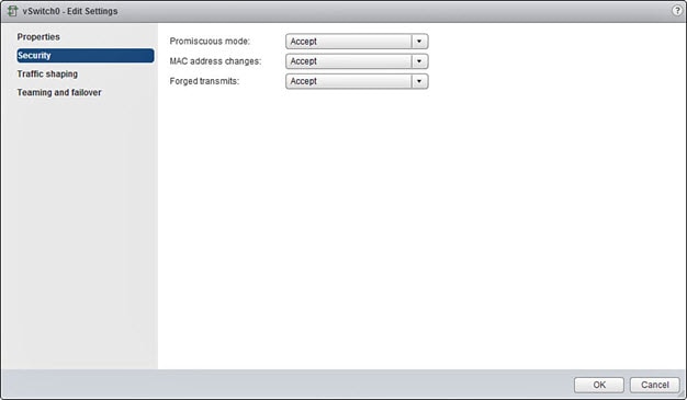
For a vSphere standard switch, the three elements of the Layer 2 Security policy are promiscuous mode, MAC address changes, and forged transmits. The threat defense virtual uses promiscuous mode to operate, and the threat defense virtual high availability depends on switching the MAC address between the active and the standby to operate correctly.

The default settings will block correct operation of the threat defense virtual. See the following required settings:

Table 1. vSphere Standard Switch Security Policy Options

Option

Required Setting

Action

Promiscuous Mode

Accept

You must edit the security policy for a vSphere standard switch in the vSphere Web Client and set the Promiscuous mode option to Accept.

Firewalls, port scanners, intrusion detection systems and so on, need to run in promiscuous mode.

MAC Address Changes

Accept

You should verify the security policy for a vSphere standard switch in the vSphere Web Client and confirm the MAC address changes option is set to Accept.

Forged Transmits

Accept

You should verify the security policy for a vSphere standard switch in the vSphere Web Client and confirm the Forged transmits option is set to Accept.

Use the following procedure to configure the default settings for correct operation of the threat defense virtual.

  1. In the vSphere Web Client, navigate to the HyperFlex cluster.

  2. On the Manage tab, click Networking, and select Virtual switches.

  3. Select a standard switch from the list and click Edit settings.

  4. Select Security and view the current settings.

  5. Accept promiscuous mode activation, MAC address changes, and forged transmits in the guest operating system of the virtual machines attached to the standard switch.

    Figure 1. vSwitch Edit Settings
  6. Click OK.


    Note


    Ensure these settings are the same on all networks that are configured for management and failover (HA) interfaces on the threat defense virtual devices.


Related Documents

Release Notes for Cisco HX Data Platform

Configuration Guides for Cisco HX Data Platform

Cisco HyperFlex 4.0 for Virtual Server Infrastructure with VMware ESXi

Cisco HyperFlex Systems Solutions Overview

Cisco HyperFlex Systems Documentation Roadmap

How to Manage Secure Firewall Threat Defense Virtual Device

You have two options to manage your Secure Firewall Threat Defense Virtual.

Secure Firewall Management Center

If you are managing large numbers of devices, or if you want to use the more complex features and configurations that the threat defense allows, use the management center to configure your devices instead of the integrated device manager.


Important


You cannot use both the device manager and the management center to manage the threat defense device. Once the device manager integrated management is enabled, it won't be possible to use the management center to manage the threat defense device, unless you disable the local management and re-configure the management to use the management center. On the other hand, when you register the threat defense device to the management center, the device manager onboard management service is disabled.


Caution


Currently, Cisco does not have an option to migrate your device manager configuration to the management center and vice-versa. Take this into consideration when you choose what type of management you configure for the threat defense device.


Secure Firewall device manager

The device manager is an onboard integrated manager.

The device manager is a web-based configuration interface included on some of the threat defense devices. The device manager lets you configure the basic features of the software that are most commonly used for small networks. It is especially designed for networks that include a single device or just a few, where you do not want to use a high-powered multiple-device manager to control a large network containing many of the threat defense devices.


Note


See the Cisco Secure Firewall Device Manager Configuration Guide for list of the threat defense devices that support the device manager.


Overview

You can deploy the threat defense virtual to Cisco HyperFlex on a VMware vCenter server.

To successfully deploy the threat defense virtual, you must be familiar with VMware and vSphere, including vSphere networking, ESXi host setup and configuration, and virtual machine guest deployment.

The threat defense virtual for Cisco HyperFlex is distributed using the Open Virtualization Format (OVF), a standard method of packaging and deploying virtual machines. VMware provides several ways to provision vSphere virtual machines. The optimal way for your environment depends on the size and type of your infrastructure and the goals you want to achieve.

You can use the VMware vSphere Web Client to access your Cisco HyperFlex environment.

Deploy the Threat Defense Virtual

Use this procedure to deploy the threat defense virtual appliance to Cisco HyperFlex on a vSphere vCenter Server.

Before you begin

  • Ensure that you have deployed Cisco HyperFlex and performed all the post-installation configuration tasks. For more information, see Cisco HyperFlex Systems Documentation Roadmap.

  • You must have at least one network configured in vSphere (for management) before you deploy the threat defense virtual.

  • Download the threat defense virtual VI OVF template file from Cisco.com: Cisco_Firepower_Threat_Defense_Virtual-VI-X.X.X-xxx.ovf, where X.X.X-xxx is the version and build number.

Procedure


Step 1

Log in to the vSphere Web Client.

Step 2

Select the HyperFlex cluster where you want to deploy the threat defense virtual, and click ACTIONS > Deploy OVF Template.

Step 3

Browse your file system for the OVF template source location, and click NEXT.

Select the threat defense virtual VI OVF template:

Cisco_Firepower_Threat_Defense_Virtual-VI-X.X.X-xxx.ovf

where X.X.X-xxx is the version and build number of the archive file you downloaded.

Step 4

Specify a name and location for the threat defense virtual, and click NEXT.

Step 5

Select a compute resource, and wait until the compatibility check is complete.

If the compatibility check succeeds, click NEXT.

Step 6

Review the OVF template information (product name, version, vendor, download size, size on disk, and description), and click NEXT.

Step 7

Review and accept the license agreement that is packaged with the OVF template (VI templates only), and click NEXT.

Step 8

Select a deployment configuration (vCPU/memory values), and click NEXT.

Step 9

Select a storage location and virtual disk format, and click NEXT.

On this window, select from datastores already configured on the destination HyperFlex cluster. The virtual machine configuration file and virtual disk files that are stored on the datastore. Select a datastore large enough to accommodate the virtual machine and all of its virtual disk files.

When you select Thick Provisioned as the virtual disk format, all storage is immediately allocated. When you select Thin Provisioned as the virtual disk format, storage is allocated on demand as data is written to the virtual disks. Thin provisioning can also reduce the amount of time it takes to deploy the virtual appliance.

Step 10

Map the networks specified in the OVF template to networks in your inventory, and click NEXT.

Ensure the Management0-0 interface is associated with a VM Network that is reachable from the Internet. Non-management interfaces are configurable from either the management center or from the device manager, depending on your management mode.

The networks may not be in alphabetical order. If it is too difficult to find your networks, you can change the networks later from the Edit Settings dialog box. After you deploy, right-click the threat defense virtual instance, and choose Edit Settings. However, that screen does not show the threat defense virtual IDs (only Network Adapter IDs).

See the following concordance of Network Adapter, Source Networks and Destination Networks for the threat defense virtual interfaces (note these are the default vmxnet3 interfaces):

Network Adapter

Source Networks

Destination Networks

Function

Network adapter 1

Management0-0

Management0/0

Management

Network adapter 2

Diagnostic0-0

Diagnostic0/0

Diagnostic

Network adapter 3

GigabitEthernet0-0

GigabitEthernet0/0

Outside data

Network adapter 4

GigabitEthernet0-1

GigabitEthernet0/1

Inside date

Network adapter 5

GigabitEthernet0-2

GigabitEthernet0/2

Data traffic (Optional)

Network adapter 6

GigabitEthernet0-3

GigabitEthernet0/3

Data traffic (Optional)

Network adapter 7

GigabitEthernet0-4

GigabitEthernet0/4

Data traffic (Optional)

Network adapter 8

GigabitEthernet0-5

GigabitEthernet0/5

Data traffic (Optional)

Network adapter 9

GigabitEthernet0-6

GigabitEthernet0/6

Data traffic (Optional)

Network adapter 10

GigabitEthernet0-7

GigabitEthernet0/7

Data traffic (Optional)

You can have a total of 10 interfaces when you deploy the threat defense virtual. For data interfaces, make sure that the Source Networks map to the correct Destination Networks, and that each data interface maps to a unique subnet or VLAN. You do not need to use all the threat defense virtual interfaces; for interfaces you do not intend to use, you can simply leave the interface disabled within the threat defense virtual configuration.

Step 11

Set the user-configurable properties packaged with the OVF template:

Note


We recommend that you configure all the required customizations in this step. If you did not configure all the required customizations, you must complete the setup by logging in to the CLI after the deployment. For instructions, see Complete the Threat Defense Virtual Setup using CLI.

  1. Password

    Set the password for the threat defense virtual admin access.

  2. Network

    Set the network information, including the Fully Qualified Domain Name (FQDN), DNS, search domain, and network protocol (IPv4 or IPv6).

  3. Management

    Set the management mode. Click the drop-down arrow for Enable Local Manager and select Yes to use the integrated device manager web-based configuration tool. Select No to use the management center to manage this device.

  4. Firewall Mode

    Set the initial firewall mode. Click the drop-down arrow for Firewall Mode and choose one of the two supported modes, either Routed or Transparent.

    If you chose Yes for Enable Local Manager, you can only select Routed firewall mode. You cannot configure transparent firewall mode interfaces using the local device manager.

  5. Registration

    If you chose No for Enable Local Manager, you need to provide the required credentials to register this device to the managing Firepower Management Center. Provide the following:

    • Managing Defense Center—Enter the hostname or IP address of the management center.

    • Registration Key—The registration key is a user-generated one-time use key that must not exceed 37 characters. Valid characters include alphanumerical characters (A–Z, a–z, 0–9) and the hyphen (-). You must remember this registration key when you add the device to the management center.

    • NAT ID—If the threat defense virtual and the management center are separated by a Network Address Translation (NAT) device, and the management centerr is behind a NAT device, enter a unique NAT ID. This is a user-generated one-time use key that must not exceed 37 characters. Valid characters include alphanumerical characters (A–Z, a–z, 0–9) and the hyphen (-).

  6. Click NEXT.

Step 12

Review and verify the displayed information. To begin the deployment with these settings, click FINISH. To make any changes, click BACK to navigate back through the screens.

After you complete the wizard, the vSphere Web Client processes the virtual machine; you can see the “Initialize OVF deployment” status in the Global Information area Recent Tasks pane.

When it is finished, you see the Deploy OVF Template completion status.

The threat defense virtual virtual instance appears under the specified data center in the Inventory. Booting up the new VM could take up to 30 minutes.

Note


To successfully register the threat defense virtual with the Cisco Licensing Authority, the threat defense virtual requires Internet access. You need to perform additional configuration after deployment to achieve Internet access and successful license registration.


What to do next

Your next steps depend on what management mode you chose.


Note


If you did not configure all the required customizations while deploying the threat defense virtual, you must complete the setup using the CLI. For instructions, see Complete the Threat Defense Virtual Setup using CLI.


Complete the Threat Defense Virtual Setup using CLI

If you did not configure all the required customizations while deploying the threat defense virtual, you must complete the setup using the CLI.

Procedure


Step 1

Open the VMware console.

Step 2

At the firepower login prompt, log in with the default credentials of username admin and the password Admin123.

Step 3

When the threat defense system boots, a setup wizard prompts you for the following information required to configure the system:

  • Accept EULA

  • New admin password

  • IPv4 or IPv6 configuration

  • IPv4 or IPv6 DHCP settings

  • Management port IPv4 address and subnet mask, or IPv6 address and prefix

  • System name

  • Default gateway

  • DNS setup

  • HTTP proxy

  • Management mode (local management uses the device manager).

Step 4

Review the Setup wizard settings. Defaults or previously entered values appear in brackets. To accept previously entered values, press Enter.

The VMware console may display messages as your settings are implemented.

Step 5

Complete the system configuration as prompted.

Step 6

Verify the setup was successful when the console returns to the # prompt.

Note

 
To successfully register the threat defense virtual with the Cisco Licensing Authority, the threat defense virtual requires Internet access. You might need to perform additional configuration after deployment to achieve Internet access and successful license registration.

What to do next

Your next steps depend on what management mode you chose.

Enabling Jumbo Frames

A larger MTU allows you to send larger packets. Larger packets might be more efficient for your network. See the following guidelines:

  • Matching MTUs on the traffic path—We recommend that you set the MTU on all ASAv interfaces and other device interfaces along the traffic path to be the same. Matching MTUs prevents intermediate devices from fragmenting the packets.

  • Accommodating jumbo frames—You can set the MTU up to 9198 bytes. The maximum is 9000 for the ASAv.

This procedure explains how to enable jumbo frames in the following environment:

HyperFlex Cluster on the vSphere 7.0.1 > VMware vSphere vSwitch> Cisco UCS Fabric Interconnects (FI).

Procedure


Step 1

Change the MTU settings of the ASAv host where you have deployed the ASAv.

  1. Connect to the vCenter Server using the vSphere Web Client.

  2. In the Advanced System Settings of your HyperFlex host, set the value of the configuration parameter—Net.Vmxnet3NonTsoPacketGtMtuAllowed to 1.

  3. Save the changes and reboot the host.

For more information, see https://kb.vmware.com/s/article/1038578.

Step 2

Change the MTU settings of the VMware vSphere vSwitch.

  1. Connect to the vCenter Server using the vSphere Web Client.

  2. Edit the properties of the VMware vSphere vSwitch, and set the value of MTU to 9000.

Step 3

Change the MTU settings of the Cisco UCS Fabric Interconnects (FI).

  1. Log in to the Cisco UCS Management console.

  2. To Edit QoS System Class, choose LAN > LAN Cloud > QoS System Class. Under the General tab, set the value of MTU to 9216.

  3. To edit your vNIC, choose LAN > Policies > root > Sub-Organizations

    <your-hyperflex-org>vNIC Templates <your-vnic>. Under the General tab, set the value of MTU to 9000.


Troubleshooting

This section provides you with some basic troubleshooting steps related to your Hyperflex deployment on your virtual machine.

Verify whether your virtual machine is running the HyperFlex

If the threat defense virtual appliance is installed on the HyperFlex with ESX OS, the default vSphere HA policy created by the HX post_install script is causing an error message when the threat defense virtual is powered on. The error message will say:

"Power on Failures: Insufficient resources to satisfy configured failover level for vSphere HA."

Workaround

  1. In VMware vCenter, go to HX cluster > Configure > vSphere Availability > Edit Vsphere HA > Admission Control > Define host failover capacity > Override calculated failover capacity.

  2. Change and tune reserved failover CPU, and Memory capacity percentage.

  3. Power on the threat defense virtual VM.