- Preface
- Introducing the Sensor
- Preparing the Appliance for Installation
- Installing the IPS 4270-20
- Installing the IPS 4345 and IPS 4360
- Installing the IPS 4510 and IPS 4520
- Installing and Removing the ASA 5500 AIP SSM
- Installing and Removing the ASA 5585-X IPS SSP
- Logging In to the Sensor
- Initializing the Sensor
- Obtaining Software
- Upgrading, Downgrading, and Installing System Images
- Troubleshooting
- Cable Pinouts
- Glossary
- hwguide71IX
Cisco Intrusion Prevention System Appliance and Module Installation Guide for IPS 7.1
Bias-Free Language
The documentation set for this product strives to use bias-free language. For the purposes of this documentation set, bias-free is defined as language that does not imply discrimination based on age, disability, gender, racial identity, ethnic identity, sexual orientation, socioeconomic status, and intersectionality. Exceptions may be present in the documentation due to language that is hardcoded in the user interfaces of the product software, language used based on RFP documentation, or language that is used by a referenced third-party product. Learn more about how Cisco is using Inclusive Language.
- Updated:
- July 3, 2012
Chapter: Installing the IPS 4345 and IPS 4360
Installing the IPS 4345 and IPS 4360
Contents
This chapter describes the Cisco IPS 4345 and the IPS 4360, and includes the following sections:
Installation Notes and Caveats
Pay attention to the following notes and caveats before installing the IPS 4345 and the IPS 4360.

Note![]() Read through the entire guide before beginning any of the installation procedures.
Read through the entire guide before beginning any of the installation procedures.

Warning Only trained and qualified personnel should install, replace, or service this equipment. Statement 49

Product Overview
The IPS 4345 delivers 500 Megabits of intrusion prevention performance. You can use the IPS 4345 to protect both half Gigabit subnets and aggregated traffic traversing switches from multiple subnets. The IPS 4345 is a purpose-built device that has support for both copper and fiber NIC environments thus providing flexibility of deployment in any environment. It replaces the IPS 4240 and the IPS 4255.
The IPS 4360 delivers 1 Gigabit of intrusion prevention performance. You can use the IPS 4360 to protect Gigabit subnets and aggregated traffic traversing switches from multiple subnets. The IPS 4360 is a purpose-built device that has support for both copper and fiber NIC environments thus providing flexibility of deployment in any environment. It replaces the IPS 4260.
All connectivity is on the back of the appliance. The IPS 4345 and the IPS 4360 have eight Gigabit Ethernet network ports. The network port numbers increase from right to left and from bottom to top. There is also a built-in management port, a console interface, and 2 USB ports.
The IPS 4345 monitors 500 Megabits of aggregate network traffic on multiple sensing interfaces and is also inline ready. It supports both copper and fiber interfaces. The 500 Mbps performance is traffic combined from all sensing interfaces. The 500 Mbps performance for the IPS 4345 is based on multiple models of common traffic mixes based on common deployment scenarios while running IPS 7.1.(3)E4 software.
The IPS 4360 monitors greater than 1 Gbps of aggregate network traffic on multiple sensing interfaces and is also inline ready. It supports both copper and fiber interfaces. The 1-Gbps performance is traffic combined from all sensing interfaces. The 1-Gbps performance for the IPS 4360 is based on multiple models of common traffic mixes based on common deployment scenarios while running IPS 7.1.(3)E4 software.
Specifications
Table 4-1 lists the specifications for the IPS 4345 and the IPS 4360.
Accessories
Figure 4-1 and Figure 4-2 display the contents of the sensor packing box, which contains the items you need to install the sensor.
Figure 4-1 IPS 4345 Packing Box Contents

|
|
|
||
|
|
|
||
|
|
|
||
|
|
|
Figure 4-2 IPS 4360 Packing Box Contents

|
|
|
||
|
|
|
||
|
|
|
||
|
|
|
Front and Back Panel Features
This section describes the IPS 4345 and IPS 4360 front and back panel features and indicators. Figure 4-3 shows the front view of the IPS 4345 and IPS 4360.
Figure 4-3 IPS 4345 and IPS 4360 Front Panel View

|
|
|
Figure 4-4 shows the indicators for the IPS 4345. These indicators are also found on the back panel of the IPS 4345.
Figure 4-4 IPS 4345 Indicators

Figure 4-5 shows the indicators for the IPS 4360. These indicators are also found on the back panel of the IPS 4360.
Figure 4-5 IPS 4360 Indicators

Table 4-2 describes the indicators on the IPS 4345 and IPS 4360.
Figure 4-6 shows the back panel features of the IPS 4345.
Figure 4-6 IPS 4345 Back Panel Features

|
|
|
||
|
|
Management port1 |
|
Network interface ports |
|
|
|
||
|
|
Serial console port2 |
|
Figure 4-7 shows the back panel features of the IPS 4360.
Figure 4-7 IPS 4360 Back Panel Features

|
|
|
||
|
|
Management port3 |
|
Network interface ports |
|
|
|
||
|
|
Serial console port4 |
|
Table 4-3 describes the rear MGMT and network interface indicators.
|
|
|
|
|---|---|---|
Rack Mount Installation
This section describes how to rack mount the 4300 series chassis, and contains the following topics:
- Rack-Mounting Guidelines
- Installing the IPS 4345 in a Rack
- Mounting the IPS 4345 and IPS 4360 in a Rack with the Slide Rail Mounting System
Rack-Mounting Guidelines
Warning Warning To prevent bodily injury when mounting or servicing this unit in a rack, you must take special precautions to ensure that the system remains stable. The following guidelines are provided to ensure your safety: This unit should be mounted at the bottom of the rack if it is the only unit in the rack.When mounting this unit in a partially filled rack, load the rack from the bottom to the top with the heaviest component at the bottom of the rack.If the rack is provided with stabilizing devices, install the stabilizers before mounting or servicing the unit in the rack. Statement 1006
Pay attention to the following guidelines before rack-mounting your appliance:
If the rack contains stabilizing devices, install the stabilizers prior to mounting or servicing the appliance in the rack.
- When mounting an appliance in an enclosed rack, ensure adequate ventilation. Do not overcrowd an enclosed rack. Make sure that the rack is not congested, because each component generates heat.
- When mounting an appliance in an open rack, make sure that the rack frame does not block the intake or exhaust ports.
- If the rack contains only one appliance, mount the appliance at the bottom of the rack.
- If the rack is partially filled, load the rack from the bottom to the top, with the heaviest component at the bottom of the rack.
Note![]() Use the rack mount brackets to mount the IPS 4345. Use the slide rail mounting system to mount the IPS 4360.
Use the rack mount brackets to mount the IPS 4345. Use the slide rail mounting system to mount the IPS 4360.
Installing the IPS 4345 in a Rack
The IPS 4345 ships with the rack mount brackets installed on the front of the chassis. Use these brackets to mount the chassis to the front of the rack. If you want to mount the chassis on the back of the rack, you can move the brackets from the front to the back of the chassis.
To rack-mount the chassis, perform the following steps:
Step 1![]() If you are keeping the front rack mount brackets, go to Step 4. If you want to move the front rack mount brackets to the back of the chassis, go to Step 2.
If you are keeping the front rack mount brackets, go to Step 4. If you want to move the front rack mount brackets to the back of the chassis, go to Step 2.
Step 2![]() Remove the rack-mount brackets from the chassis as shown in Figure 4-8.
Remove the rack-mount brackets from the chassis as shown in Figure 4-8.
Figure 4-8 Removing the Brackets from the Front of the Chassis

Step 3![]() Install the brackets on the back of the chassis by attaching the brackets to the holes in the chassis as shown in Figure 4-9. After the brackets are secured to the chassis, you can rack-mount it.
Install the brackets on the back of the chassis by attaching the brackets to the holes in the chassis as shown in Figure 4-9. After the brackets are secured to the chassis, you can rack-mount it.
Figure 4-9 Installing the Brackets on the Back of the Chassis

Step 4![]() Attach the chassis to the rack using the supplied screws (Figure 4-10).
Attach the chassis to the rack using the supplied screws (Figure 4-10).
Figure 4-10 Rack-Mounting the Chassis

Step 5![]() To remove the chassis from the rack, remove the screws that attach the chassis to the rack, and then remove the chassis.
To remove the chassis from the rack, remove the screws that attach the chassis to the rack, and then remove the chassis.
Mounting the IPS 4345 and IPS 4360 in a Rack with the Slide Rail Mounting System
The IPS 4360 ships with the slide rail mounting system, which provides a quick, convenient, and secure method for rack mounting the IPS 4360. You can also use the slide rail mounting system with the IPS 4345. For instructions for using the slide rail mounting system, refer to the Slide Rail Installation Instructions for Cisco IronPort C170, M170, and S170 Appliances and Cisco 5512-X, 5515-X, 5525-X, 5545-X, 5555-X Adaptive Security Appliances and Cisco IPS 4345 and 4360 found at this URL:
http://www.cisco.com/en/US/docs/security/asa/hw/maintenance/5500xspares/slide_rail_installation.htm l
Although slide rail mounting is preferred for the IPS 4360, in the case of two-rail racks where the slide rails will not fit, you can use the rack mounting brackets. You must order them separately (ASA-BRACKETS=). Note that there will be a slight bend in the brackets when you attach them.
For the procedure for attaching the rack mounting brackets, see Installing the IPS 4345 in a Rack.
Installing the Appliance on the Network
Warning IMPORTANT SAFETY INSTRUCTIONS
This warning symbol means danger. You are in a situation that could cause bodily injury. Before you work on any equipment, be aware of the hazards involved with electrical circuitry and be familiar with standard practices for preventing accidents. Use the statement number provided at the end of each warning to locate its translation in the translated safety warnings that accompanied this device. Statement 1071
SAVE THESE INSTRUCTIONS
Warning Only trained and qualified personnel should be allowed to install, replace, or service this equipment. Statement 1030
To install the appliance on the network, follow these steps:
Step 2![]() Install the appliance in a rack, if you are rack mounting it.
Install the appliance in a rack, if you are rack mounting it.
Step 3![]() Before connecting a computer or terminal to the ports, check to determine the baud rate of the serial port.
Before connecting a computer or terminal to the ports, check to determine the baud rate of the serial port.
The baud rate must match the default baud rate (9600 baud) of the console port of the appliance. Set up the terminal as follows: 9600 baud (default), 8 data bits, no parity, 1 stop bits, and Flow Control (FC) = Hardware.
Step 4![]() Connect to the management port. Connect one RJ-45 connector to the management port and connect the other end to the management port on your computer or network device. The appliance has a dedicated management interface referred to as Management 0/0, which is a GigabitEthernet interface with a dedicated port used only for traffic management.
Connect to the management port. Connect one RJ-45 connector to the management port and connect the other end to the management port on your computer or network device. The appliance has a dedicated management interface referred to as Management 0/0, which is a GigabitEthernet interface with a dedicated port used only for traffic management.

|
|
|
Step 5![]() Connect to the console port. The console cable has a DB-9 connector on one end for the serial port on your computer, and the other end is an RJ-45 connector. Connect the RJ-45 connector to the console port on the appliance, and connect the other end of the cable, the DB-9 connector, to the console port on your computer.
Connect to the console port. The console cable has a DB-9 connector on one end for the serial port on your computer, and the other end is an RJ-45 connector. Connect the RJ-45 connector to the console port on the appliance, and connect the other end of the cable, the DB-9 connector, to the console port on your computer.

|
|
|
Step 6![]() Connect to the Ethernet ports. Connect the RJ-45 connector to the Ethernet port and connect the other end of the RJ-45 connector to your network device, such as a router, switch, or hub.
Connect to the Ethernet ports. Connect the RJ-45 connector to the Ethernet port and connect the other end of the RJ-45 connector to your network device, such as a router, switch, or hub.

|
|
|
Step 7![]() Attach the power cable to the appliance and plug the other end in to a power source (a UPS is recommended).
Attach the power cable to the appliance and plug the other end in to a power source (a UPS is recommended).
Step 8![]() Power on the appliance.
Power on the appliance.
Step 9![]() Initialize the appliance.
Initialize the appliance.
Step 10![]() Install the most recent Cisco IPS software. You are now ready to configure intrusion prevention on the appliance.
Install the most recent Cisco IPS software. You are now ready to configure intrusion prevention on the appliance.
- For more information about ESD, see Preventing Electrostatic Discharge Damage.
- For the procedure for using the setup command to initialize the appliance, see Appendix B, “Initializing the Sensor.”
- For the procedure for obtaining IPS software, see Obtaining Cisco IPS Software.
- For the procedures for configuring intrusion prevention on your sensor, refer to the following documents:
Removing and Installing the Power Supply
This section describes the AC and DC power supplies and how to install and remove them. It contains the following topics:
- AC Power Supply in V01 and V02 Chassis
- Understanding the Power Supplies
- Removing and Installing the AC Power Supply
- Installing DC Input Power
- Removing and Installing the DC Power Supply
AC Power Supply in V01 and V02 Chassis
The Cisco IPS 4300 series sensors with the AC power supply can restore the previous power state of the system if AC power is lost. Earlier IPS 4300s (V01) require you to turn on the power with the power switch. Newer IPS 4300s (V02) automatically turn on when you plug in the power cable. To determine your version, do one of the following:
- At the CLI, enter the show inventory command and look for V01 or V02 in the output.
- On the back of the chassis, look at the VID PID label for V01 or V02.
The V01 chassis has the following limitations (these limitations do not apply to the V02 chassis):
- The sensor requires 50 seconds from the time that AC power is applied before the power state can be updated and stored. This means that any changes to the power state within the first 50 seconds of applying AC power will not be observed if AC power is removed within that time.
- The sensor requires 10 seconds from the time it is placed into standby mode before the power state can be updated and stored. This means any changes to the power state within the first 10 seconds of entering standby mode (including the standby mode itself) will not be observed if AC power is removed within that time.
Understanding the Power Supplies
The IPS 4345 ships with one fixed fan and one fixed power supply (AC or DC) installed. The IPS 4360 ships with one power supply (AC or DC) installed. You can add an additional power supply or you can order the IPS 4360 with two power supplies installed. Having two power supplies installed provides a redundant power option. This configuration ensures that if one power supply fails, the other power supply assumes the full load until the failed power supply is replaced. To maintain airflow, an empty bay must be covered or both bays must be populated with power supplies. If only one power supply is installed, make sure that it is installed in slot 0 (left slot) and that slot 1 (right slot) is covered with a slot cover. If only one power supply is installed, do not remove the power supply unless the appliance has been powered off. Removing the only operational power supply causes an immediate power loss.
Note![]() The IPS 4360 can support two AC or two DC power supplies. Do not mix AC and DC power supply units in the same chassis.
The IPS 4360 can support two AC or two DC power supplies. Do not mix AC and DC power supply units in the same chassis.
The power supplies each provide 400 W of output power and are used in a 1 + 1 redundant configuration. There is no input switch on the faceplate of the power supplies. The power supply is switched from Standby to ON by way of a system chassis STANDBY/ON switch. The power supply slot numbers are on the back of the chassis to the left side of each power supply. When facing the back of the chassis, power supply slot 0 (PS0) is to the left and power supply slot 1(PS1) is to the right. By default, the factory installs a single power supply in slot 0.
The appliance supports the following power supplies:
- AC power supply—Provides 400 watt output power with two DC voltage outputs: +12 V and +5 V. The AC power supply operates between 85 and 264 VAC. The AC power supply current shares on the 12 V output and is used in a dual hot pluggable configuration. The AC power supply consumes a maximum of 471 W of input power.
- DC power supply—Provides 400 watt output power with two DC voltage outputs: +12 V and +5.0 V. The power supply operates between –40.5 and –72 VDC. The DC power supply current shares on the 12 V output and is used in a dual hot pluggable configuration. The DC power supply consumes a maximum of 500 W of input power.
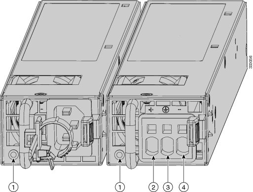
Figure 4-11 shows both the removable AC (on the left) and DC (on the right) power supplies for the IPS 4360.
Figure 4-11 AC Power Supply and DC Power Supply
|
|
|
||
|
|
|
Table 4-4 describes the power supply indicator. The function of the indicator is the same for both the AC and DC power supplies.
Removing and Installing the AC Power Supply
Warning This unit has more than one power supply connection; all connections must be removed completely to completely remove power from the unit. Statement 102
Warning This product relies on the building’s installation for short-circuit (overcurrent) protection. Ensure that the protective device is rated not greater than: 120 VAC, 20A U.S. (240 VAC, 10A international). Statement 1005
Note![]() This procedure applies only to the appliances with a removable AC power supply (IPS 4360).
This procedure applies only to the appliances with a removable AC power supply (IPS 4360).
Note![]() If only one power supply is installed, make sure that it is installed in slot 0 (left slot) and that slot 1 (right slot) is covered with a slot cover.
If only one power supply is installed, make sure that it is installed in slot 0 (left slot) and that slot 1 (right slot) is covered with a slot cover.
To remove and install the AC power supply, follow these steps:
Step 1![]() If you are adding an additional power supply, from the back of the appliance, push the lever on the slot cover to the left to release it, grasp the handle of the slot cover and pull it away from the chassis (Figure 4-12). Save the slot cover for future use. Continue with Step 3.
If you are adding an additional power supply, from the back of the appliance, push the lever on the slot cover to the left to release it, grasp the handle of the slot cover and pull it away from the chassis (Figure 4-12). Save the slot cover for future use. Continue with Step 3.
Figure 4-12 Removing the Slot Cover

Step 2![]() If you are replacing a power supply, follow these steps:
If you are replacing a power supply, follow these steps:
b.![]() From the back panel of the appliance, unplug the power supply cable.
From the back panel of the appliance, unplug the power supply cable.
c.![]() Push the lever on the power supply to the left and remove the power supply by grasping the handle and then pulling the power supply away from the chassis while supporting it from beneath with the other hand (Figure 4-13). Continue with Step 3.
Push the lever on the power supply to the left and remove the power supply by grasping the handle and then pulling the power supply away from the chassis while supporting it from beneath with the other hand (Figure 4-13). Continue with Step 3.
Figure 4-13 Removing the AC Power Supply

Step 3![]() Install the new power supply by aligning it with the power supply bay and pushing it into place until it is seated while supporting it from beneath with the other hand (Figure 4-14).
Install the new power supply by aligning it with the power supply bay and pushing it into place until it is seated while supporting it from beneath with the other hand (Figure 4-14).
Figure 4-14 Installing the AC Power Supply

Step 4![]() Connect the power cable. If you are installing two power supplies for a redundant configuration, plug each one into a power source (we recommend a UPS).
Connect the power cable. If you are installing two power supplies for a redundant configuration, plug each one into a power source (we recommend a UPS).
Step 5![]() Power on the appliance if you powered it off to replace the only power supply.
Power on the appliance if you powered it off to replace the only power supply.
Step 6![]() Check the PS0 and PS1 indicators on the front panel to make sure they are green. On the back panel of the appliance, make sure the power supply indicator on the bottom of each installed power supply is green (Figure 4-15).
Check the PS0 and PS1 indicators on the front panel to make sure they are green. On the back panel of the appliance, make sure the power supply indicator on the bottom of each installed power supply is green (Figure 4-15).
Figure 4-15 Back Power Supply Indicators

Installing DC Input Power
Warning The covers are an integral part of the safety design of the product. Do not operate the unit without the covers installed. Statement 1077
Warning When you install the unit, the ground connection must always be made first and disconnected last. Statement 1046
Warning Before performing any of the following procedures, ensure that power is removed from the DC circuit. Statement 1003
Warning Only trained and qualified personnel should be allowed to install, replace, or service this equipment. Statement 1030
Warning This product relies on the building’s installation for short-circuit (overcurrent) protection. Ensure that the protective device is rated not greater than: 80 VAC, 20A. Statement 1005
The DC power supply is shipped installed in the chassis, either one or two power supplies depending on which configuration you ordered. You must connect the power supply wires. This section describes how to install the DC power supply ground leads and input power leads to the appliance DC input power supply. Before you begin, read these important notices:
- The color coding of the DC input power supply leads depends on the color coding of the DC power source at your site. Typically, green or green/yellow is used for ground (GND), black is used for –48 V on the negative (–) terminal, and red is used for RTN on the positive (+) terminal. Ensure that the lead color coding you choose for the DC input power supply matches the lead color coding used at the DC power source.
- Make sure that the chassis ground is connected on the chassis before you begin installing the DC power supply. For more information, see Working in an ESD Environment.
Figure 4-16 shows the back panel of the IPS 4345 with the DC power supply.
Figure 4-16 IPS 4345 Back Panel

|
|
|
Figure 4-17 shows the back panel of the IPS 4360 with two DC power supplies.
Figure 4-17 IPS 4360 Back Panel

Note![]() If only one power supply is installed, make sure that it is installed in slot 0 (left slot) and that slot 1 (right slot) is covered with a slot cover.
If only one power supply is installed, make sure that it is installed in slot 0 (left slot) and that slot 1 (right slot) is covered with a slot cover.
To connect the DC power supply on the appliance, follow these steps:
Step 1![]() Make sure that the chassis ground is connected on the chassis before you begin installing the DC power supply.
Make sure that the chassis ground is connected on the chassis before you begin installing the DC power supply.
Step 2![]() Turn off the circuit breaker to the power supply.
Turn off the circuit breaker to the power supply.
Step 3![]() From the front of the appliance, verify that the power switch is in the Standby position.
From the front of the appliance, verify that the power switch is in the Standby position.
Step 4![]() Move the circuit-breaker switch handle to the Off position, and apply tape to hold it in the Off position.
Move the circuit-breaker switch handle to the Off position, and apply tape to hold it in the Off position.
Step 5![]() Use a 10 gauge wire-stripping tool to strip each of the three wires coming from the DC input power source. Strip the wires to 0.27 inch (7 mm) + 0.02 inch (0.5 mm). Do not strip more than the recommended length of wire because doing so could leave the wire exposed from the DC power supply connection (Figure 4-18).
Use a 10 gauge wire-stripping tool to strip each of the three wires coming from the DC input power source. Strip the wires to 0.27 inch (7 mm) + 0.02 inch (0.5 mm). Do not strip more than the recommended length of wire because doing so could leave the wire exposed from the DC power supply connection (Figure 4-18).
Figure 4-18 Stripping the DC Input Power Source Wire

|
|
Warning An exposed wire lead from a DC input power source can conduct harmful levels of electricity. Be sure that no exposed portion of the DC input power source wire extends from the terminal block plug. Statement 122
Step 6![]() Identify the positive, negative, and ground feed positions for the DC power supply connection. The recommended wiring sequence is as follows (Figure 4-19):
Identify the positive, negative, and ground feed positions for the DC power supply connection. The recommended wiring sequence is as follows (Figure 4-19):

|
|
|
||
|
|
|
Figure 4-20 shows the DC power supply with lead wires.
Figure 4-20 DC Power Supply with Lead Wires

Step 7![]() Insert the exposed end of one of the ground wires into the inlet on the DC power supply. After you push in the wires, they are held in place with a spring, which makes the physical contact. Make sure that you cannot see any wire lead. Only wires with insulation should extend from the DC power supply.
Insert the exposed end of one of the ground wires into the inlet on the DC power supply. After you push in the wires, they are held in place with a spring, which makes the physical contact. Make sure that you cannot see any wire lead. Only wires with insulation should extend from the DC power supply.
Step 8![]() Repeat Step 5 through Step 7 for the remaining two DC input power source wires, the positive lead wire and the negative lead wire.
Repeat Step 5 through Step 7 for the remaining two DC input power source wires, the positive lead wire and the negative lead wire.
Step 9![]() Use a tie wrap to secure the wires coming from the power supply to the rack so that the wires cannot be pulled from the power supply by casual contact. Make sure the tie wrap allows for some slack in the ground wire. Figure 4-21 shows the DC power supply with the wires inserted and the tie wrap secured.
Use a tie wrap to secure the wires coming from the power supply to the rack so that the wires cannot be pulled from the power supply by casual contact. Make sure the tie wrap allows for some slack in the ground wire. Figure 4-21 shows the DC power supply with the wires inserted and the tie wrap secured.
Figure 4-21 Complete DC Secure Tie Wrap

|
|
|
Step 10![]() Remove the tape (if any) from the circuit breaker switch handle, and move the circuit breaker switch handle to the On position. The power supply indicators light up when power is supplied to the appliance.
Remove the tape (if any) from the circuit breaker switch handle, and move the circuit breaker switch handle to the On position. The power supply indicators light up when power is supplied to the appliance.
Removing and Installing the DC Power Supply
Note![]() This procedure applies only to the appliances with a removable DC power supply (IPS 4360).
This procedure applies only to the appliances with a removable DC power supply (IPS 4360).
To remove and install a DC power supply, follow these steps:
Step 1![]() Make sure that the chassis ground is connected on the chassis before you begin installing the DC power supply, as described in Working in an ESD Environment.
Make sure that the chassis ground is connected on the chassis before you begin installing the DC power supply, as described in Working in an ESD Environment.
Step 2![]() Turn off the circuit breaker to the power supply.
Turn off the circuit breaker to the power supply.
Step 3![]() At the back of the appliance, place the Standby switch into the Standby position.
At the back of the appliance, place the Standby switch into the Standby position.
Step 4![]() Move the circuit-breaker switch handle to the Off position, and apply tape to hold it in the Off position.
Move the circuit-breaker switch handle to the Off position, and apply tape to hold it in the Off position.
Step 5![]() If you are adding an additional power supply, from the back of the appliance, push the lever on the slot cover to the left to release it, grasp the handle of the slot cover, and pull it away from the chassis (Figure 4-22). Save the slot cover for future use. Continue with Step 7.
If you are adding an additional power supply, from the back of the appliance, push the lever on the slot cover to the left to release it, grasp the handle of the slot cover, and pull it away from the chassis (Figure 4-22). Save the slot cover for future use. Continue with Step 7.
Figure 4-22 Removing the Slot Cover

Step 6![]() If you are replacing a power supply, follow these steps:
If you are replacing a power supply, follow these steps:
a.![]() Remove the wires from the DC power supply by inserting a small flat-head screwdriver into the square hole above the wire to relieve the spring pressure (Figure 4-23).
Remove the wires from the DC power supply by inserting a small flat-head screwdriver into the square hole above the wire to relieve the spring pressure (Figure 4-23).
Figure 4-23 Removing the Wires from the DC Power Supply

b.![]() Gently pull the wires out of the power supply.
Gently pull the wires out of the power supply.
c.![]() Push the lever on the power supply to the left and remove the power supply by grasping the handle and then pulling the power supply out of the chassis while supporting it from beneath with the other hand (Figure 4-24).
Push the lever on the power supply to the left and remove the power supply by grasping the handle and then pulling the power supply out of the chassis while supporting it from beneath with the other hand (Figure 4-24).
Figure 4-24 Removing the DC Power Supply

Step 7![]() Install the new power supply by lining it up with the power supply bay and pushing it into place until it is seated while supporting it from beneath with the other hand (Figure 4-25).
Install the new power supply by lining it up with the power supply bay and pushing it into place until it is seated while supporting it from beneath with the other hand (Figure 4-25).
Figure 4-25 Installing the DC Power Supply

Step 8![]() To connect the DC input power source wires, see Step 5 though Step 10 in Installing DC Input Power.
To connect the DC input power source wires, see Step 5 though Step 10 in Installing DC Input Power.
 Feedback