Additional Installation Information

Tools Used to Create Bootable USB Device from Installation ISO File

The following table shows the tools to be used to create a bootable USB device from the installation ISO file in different versions of Cisco ISE.

Table 1. Tools Used to Create Bootable USB Device

Cisco ISE Release

Tool

Cisco ISE 3.3

Rufus

Cisco ISE 3.2

Rufus

Cisco ISE 3.1

Fedora LiveUSB-creator for SNS 3500/3600 series appliance

Rufus for SNS 3700 series appliance

Cisco ISE 3.0

Fedora LiveUSB-creator

Cisco ISE 2.7

Fedora LiveUSB-creator

Cisco ISE 2.6

Fedora Media Writer

Cisco ISE 2.4

Fedora Media Writer


Note


If you are installing Cisco ISE on Cisco SNS 3700 series appliances, you must use only Rufus to create a bootable USB device from the installation ISO file.

Cisco ISE 3.1 patch 6 and later and Cisco ISE 3.2 patch 2 and later versions support Cisco SNS 3700 series appliances.


You can download Rufus from the following location:

https://rufus.ie/downloads/

SNS Appliance Reference

Create a Bootable USB Device Using Rufus

If you are installing Cisco ISE on Cisco SNS 3700 series appliances, you must use Rufus 3.18 to create a bootable USB device from the installation ISO file. You can download Rufus from the following location:
https://rufus.ie/downloads/

Cisco ISE 3.1 patch 6 and later and Cisco ISE 3.2 patch 2 and later versions support Cisco SNS 3700 series appliances.

Before you begin

  • Download the Cisco ISE installation ISO file to the local system.

  • Use a 16-GB or 32-GB USB device.

Procedure


Step 1

Reformat the USB device using FAT16 or FAT32 to free up all the space.

Step 2

Plug in the USB device to the local system and launch Rufus.

Step 3

From the Boot Selection drop-down list, choose Disk or ISO Image.

Step 4

Click Select and choose the Cisco ISE ISO file.

Step 5

From the Partition Scheme drop-down list, choose MBR.

Step 6

From the Target System drop-down list, choose BIOS or UEFI.

Step 7

Click Start.

The progress bar indicates the progress of the bootable USB creation. After this process is complete, the content of the USB drive is available in the local system that you used to run the USB tool. There are two text files that you must manually update before you can install Cisco ISE.

Step 8

From the USB drive, open the following text files in a text editor:

  • isolinux/isolinux.cfg or syslinux/syslinux.cfg
  • EFI/BOOT/grub.cfg

Note


We recommend that you use Notepad as text editor to edit the configuration files. If you are using any other text editor tool, ensure that the end of line (EOL) characters are set to "LF" (not "CR LF"). The installation via USB doesn't work if EOL characters are set to "CR LF”.

Step 9

For SNS hardware appliance, replace the term "cdrom" with "hd:sdb1" in both the files.

Specifically, replace all instances of the "cdrom" string. For example, replace

ks=cdrom/ks.cfg

with

ks=hd:sdb1:/ks.cfg

Step 10

Open ks.cfg file and replace the term “cdrom” with “harddrive --partition=/dev/disk/by-label/ADEOS --dir=/

Step 11

Save the files and exit.

Step 12

Safely remove the USB device from the local system.

Step 13

Plug in the bootable USB device to the Cisco ISE appliance, restart the appliance, and boot from the USB drive to install Cisco ISE.


Reimage the Cisco SNS Hardware Appliance

The Cisco SNS hardware appliances do not have built-in DVD drives. Therefore, to reimage a Cisco ISE hardware appliance with Cisco ISE software, you can do one of the following:


Note


Cisco SNS hardware appliances support the Unified Extensible Firmware Interface (UEFI) secure boot feature. This feature ensures that only a Cisco-signed ISE image can be installed on the SNS hardware appliances, and prevents installation of any unsigned operating system even with physical access to the device. For example, generic operating systems, such as Red Hat Enterprise Linux or Microsoft Windows cannot boot on this appliance.


  • Use the Cisco Integrated Management Controller (Cisco IMC) interface to map the installation .iso file to the virtual DVD device.

  • Create an install DVD with the installation .iso file and plug in an USB external DVD drive and boot the appliance from the DVD drive.

  • Create a bootable USB device using the installation .iso file and boot the appliance from the USB drive.

VMware Virtual Machine


Note


The VMware form factor instructions provided in this document are applicable for Cisco ISE installed on Cisco Hyperflex as well.


Virtual Machine Resource and Performance Checks

Before installing Cisco ISE on a virtual machine, the installer performs hardware integrity checks by comparing the available hardware resources on the virtual machine with the recommended specifications.

During a VM resource check, the installer checks for the hard disk space, number of CPU cores allocated to the VM, CPU clock speed, and RAM allocated to the VM. If the VM resources do not meet the basic evaluation specifications, the installation terminates. This resource check is applicable only for ISO-based installations.

When you run the Setup program, a VM performance check is done, where the installer checks for disk I/O performance. If the disk I/O performance does not meet the recommended specifications, a warning appears on screen, but it allows you to continue with the installation.

The VM performance check is done periodically (every hour) and the results are averaged for a day. If the disk I/O performance does not meet the recommended specification, an alarm is generated.

The VM performance check can also be done on demand from the Cisco ISE CLI using the show tech-support command.

The VM resource and performance checks can be run independent of Cisco ISE installation. You can perform this test from the Cisco ISE boot menu.

Install Cisco ISE on VMware Virtual Machine Using the ISO File

This section describes how to install Cisco ISE on a VMware virtual machine using the ISO file.

Prerequisites for Configuring a VMware ESXi Server

Review the following configuration prerequisites listed in this section before you attempt to configure a VMWare ESXi server:

  • Remember to log in to the ESXi server as a user with administrative privileges (root user).

  • Cisco ISE is a 64-bit system. Before you install a 64-bit system, ensure that Virtualization Technology (VT) is enabled on the ESXi server.

  • Ensure that you allocate the recommended amount of disk space on the VMware virtual machine.

  • If you have not created a VMware virtual machine file system (VMFS), you must create one to support the Cisco ISE virtual appliance. The VMFS is set for each of the storage volumes configured on the VMware host. For VMFS5, the 1-MB block size supports up to 1.999 TB virtual disk size.

Virtualization Technology Check

If you have an ESXi server installed already, you can check if Virtualization Technology is enabled on it without rebooting the machine. To do this, use the esxcfg-info command. Here is an example:


~ # esxcfg-info |grep "HV Support"
|----HV Support............................................3
|----World Command Line.................................grep HV Support

If HV Support has a value of 3, then VT is enabled on the ESXi server and you can proceed with the installation.

If HV Support has a value of 2, then VT is supported, but not enabled on the ESXi server. You must edit the BIOS settings and enable VT on the server.

Enable Virtualization Technology on an ESXi Server

You can reuse the same hardware that you used for hosting a previous version of Cisco ISE virtual machine. However, before you install the latest release, you must enable Virtualization Technology (VT) on the ESXi server.

Procedure

Step 1

Reboot the appliance.

Step 2

Press F2 to enter setup.

Step 3

Choose Advanced > Processor Configuration.

Step 4

Select Intel(R) VT and enable it.

Step 5

Press F10 to save your changes and exit.


Configure VMware Server Interfaces for the Cisco ISE Profiler Service

Configure VMware server interfaces to support the collection of Switch Port Analyzer (SPAN) or mirrored traffic to a dedicated probe interface for the Cisco ISE Profiler Service.

Procedure

Step 1

Choose Configuration > Networking > Properties > VMNetwork (the name of your VMware server instance)VMswitch0 (one of your VMware ESXi server interfaces) Properties Security.

Step 2

In the Policy Exceptions pane on the Security tab, check the Promiscuous Mode check box.

Step 3

In the Promiscuous Mode drop-down list, choose Accept and click OK.

Repeat the same steps on the other VMware ESXi server interface used for profiler data collection of SPAN or mirrored traffic.


Connect to the VMware Server Using the Serial Console

Procedure

Step 1

Power down the particular VMware server (for example ISE-120).

Step 2

Right-click the VMware server and choose Edit.

Step 3

Click Add on the Hardware tab.

Step 4

Choose Serial Port and click Next.

Step 5

In the Serial Port Output area, click the Use physical serial port on the host or the Connect via Network radio button and click Next.

  • If you choose the Connect via Network option, you must open the firewall ports over the ESXi server.

  • If you select the Use physical serial port on the host, choose the port. You may choose one of the following two options:

    • /dev/ttyS0 (In the DOS or Windows operating system, this will appear as COM1).

    • /dev/ttyS1 (In the DOS or Windows operating system, this will appear as COM2).

Step 6

Click Next.

Step 7

In the Device Status area, check the appropriate check box. The default is Connected.

Step 8

Click OK to connect to the VMware server.


Configure a VMware Server

Before you begin

Ensure that you have read the Prerequisites for configuring a VMware Server.

Procedure

Step 1

Log in to the ESXi server.

Step 2

In the VMware vSphere Client, in the left pane, right-click your host container and choose New Virtual Machine.

Step 3

In the Select a Creation Type area, click Create a new virtual machine and click Next.

Step 4

In the Select a Name and Folder area, enter a name for the VMware system, select a location from the displayed list, and click Next.

Tip


Use the hostname that you want to use for your VMware host.

Step 5

In the Select a compute resource area, choose a destination compute resource and click Next.

Step 6

In the Select storage area, choose a datastore that has the recommended amount of space available and click Next.

Step 7

In the Select compatibility area, from the Compatible with drop-down list, choose an ESXi version that is compatible with your Cisco ISE version and click Next.

For information the ESXi versions that are compatible with your Cisco ISE release, see "Supported Virtual Environments" in the Release Notes for Cisco Identity Services Engine for your release.

Step 8

In the Select a guest OS area, carry out the following steps and then click Next:

  1. From the Guest OS Family drop-down list, choose Linux.

  2. From the Guest OS Version drop-down list, choose the supported Red Hat Enterprise Linux (RHEL) version. Cisco ISE Release 3.1 and later use RHEL 8.

Step 9

In the Customize hardware area, in the Virtual Hardware tab, carry out the following configurations and then click Next.

  1. choose the required values from the CPU and Memory drop-down lists according to the SNS series appliance you use:

    SNS 3600 Series Appliance:

    • Small—16 vCPU cores, 32 GB

    • Medium—24 vCPU cores, 96 GB

    • Large—24 vCPU cores, 256 GB

      The number of cores is twice of that present in equivalent of the Cisco Secure Network Server 3600 series, due to hyperthreading. For example, in case of Small network deployment, you must allocate 16 vCPU cores to meet the CPU specification of SNS 3615, which has 8 CPU Cores or 16 Threads.

    SNS 3700 Series Appliance:

    • Small—24 vCPU cores, 32 GB

    • Medium—40 vCPU cores, 96 GB

    • Large—40 vCPU cores, 256 GB

      The number of cores is twice of that present in equivalent of the Cisco Secure Network Server 3700 series, due to hyperthreading. For example, in case of Small network deployment, you must allocate 24 vCPU cores to meet the CPU specification of SNS 3715, which has 12 CPU Cores or 24 Threads.

    Note


    You must reserve vCPU and memory resources equivalent to the configured vCPU cores and memory allocations. Failure to do so may significantly impact Cisco ISE performance and stability. Click the CPU and Memory collapsible areas and update the reservation fields for each setting.

  2. From the New SCSI Controller drop-down list, choose Paravirtual.

  3. From the New Network and New CD/DVD Drive drop-down lists, choose the required network and ISO files.

Step 10

Choose the NIC driver from the Adapter drop-down list and click Next.

Step 11

Choose Create a new virtual disk and click Next.

Step 12

In the Disk Provisioning dialog box, click Thick provisioned, eagerly zeroed radio button, and click Next to continue.

Cisco ISE supports both thick and thin provisioning. However, we recommend that you choose thick provisioned, eagerly zeroed for better performance, especially for Monitoring nodes. If you choose thin provisioning, operations such as upgrade, backup and restore, and debug logging that require more disk space might be impacted during initial disk expansion.

Step 13

Uncheck the Support clustering features such as Fault Tolerance check box.

Step 14

In the Ready to complete area, verify the configuration details, such as name, guest OS, CPUs, memory, and disk size of the newly created VMware system.

Step 15

Click Finish.

The VMware system is now installed.


What to do next

To activate the newly created VMware system, right-click VM in the left pane of your VMware client user interface and choose Power > Power On.

Increase Virtual Machine Power-On Boot Delay Configuration

On a VMware virtual machine, the boot delay by default is set to 0. You can change this boot delay to help you choose the boot options (while resetting the Administrator password, for example).

Procedure

Step 1

From the VSphere client, right click the VM and choose Edit Settings.

Step 2

Click the Options tab.

Step 3

Choose Advanced > Boot Options.

Step 4

From the Power on Boot Delay area, select the time in milliseconds to delay the boot operation.

Step 5

Check the check box in the Force BIOS Setup area to enter into the BIOS setup screen when the VM boots the next time.

Step 6

Click OK to save your changes.


Install Cisco ISE Software on a VMware System

Before you begin
  • After installation, if you do not install a permanent license, Cisco ISE automatically installs a 90-day evaluation license that supports a maximum of 100 endpoints.

  • Download the Cisco ISE software from the Cisco Software Download Site at http://www.cisco.com/en/US/products/ps11640/index.html and burn it on a DVD. You will be required to provide your Cisco.com credentials.

  • (Optional; applicable only if you are installing Cisco ISE on VMware Cloud) The process of installing Cisco ISE on VMware Cloud is exactly the same as that of installing Cisco ISE on VMware virtual machine.

    • Cisco ISE virtual machine deployed on VMware cloud in Amazon Web Services (AWS): Cisco ISE can be hosted on software-defined data center (SDDC) provided by VMware Cloud on AWS. Ensure that appropriate security group policies are configured on VMware Cloud (under Networking and Security > Security > Gateway Firewall Settings) to enable reachability to on-premises deployment, required devices and services.

    • Cisco ISE virtual machine deployed on Azure VMware Solution (AVS): AVS runs VMware workloads natively on Microsoft Azure, where Cisco ISE can be hosted as VMware virtual machine.

Procedure

Step 1

Log in to the VMware client.

Step 2

For the VM to enter the BIOS setup mode, right-click the VM and select Edit Settings.

Step 3

Click the Options tab.

Step 4

Click Boot Options, and in the Force BIOS Setup area, check the BIOS check box to enter the BIOS setup screen when the VM boots.

Note


You must change the firmware from BIOS to EFI in the boot mode of VM settings to boot GPT partitions with 2 TB or more capacity.

If you have selected Guest OS RHEL 8 and EFI boot mode, disable the Enable UEFI Secure Boot option. This option is enabled by default for Guest operating system RHEL 8 VM.

Step 5

Click OK.

Step 6

Ensure that the Coordinated Universal Time (UTC) and the correct boot order are set in BIOS:

  1. If the VM is turned on, turn the system off.

  2. Turn on the VM.

    The system enters the BIOS setup mode.

  3. In the Main BIOS menu, using the arrow keys, navigate to the Date and Time field and press Enter.

  4. Enter the UTC/Greenwich Mean Time (GMT) time zone.

    This time zone setting ensures that the reports, logs, and posture-agent log files from the various nodes in your deployment are always synchronized with regard to the time stamps.

  5. Using the arrow keys, navigate to the Boot menu and press Enter.

  6. Using the arrow keys, select CD-ROM drive and press + to move the CD-ROM drive up the order.

  7. Using the arrow keys, navigate to the Exit menu and choose Exit Saving Changes.

  8. Choose Yes to save the changes and exit.

Step 7

Insert the Cisco ISE software DVD into the VMware ESXi host CD/DVD drive and turn on the virtual machine.

When the DVD boots, the console displays:


Automatic installation starts in 150 seconds.
Available boot options:
[1] Cisco ISE Installation (Keyboard/Monitor)
[2] Cisco ISE Installation (Serial Console)
[3] System Utilities (Keyboard/Monitor)
[4] System Utilities (Serial Console)
[5] Hard Disk
Enter boot option and press <Enter>.
boot: 

Step 8

Use the arrow keys to select Cisco ISE Installation (Serial Console) or Cisco ISE Installation (Keyboard/Monitor) and press Enter. If you choose the serial console option, you should have a serial console set up on your virtual machine. See the VMware vSphere Documentation for information on how to create a console.

The installer starts the installation of the Cisco ISE software on the VMware system. Allow 20 minutes for the installation process to complete. When the installation process finishes, the virtual machine reboots automatically. When the VM reboots, the console displays:
Type 'setup' to configure your appliance
localhost:

Step 9

At the system prompt, type setup and press Enter.

Note


From Cisco ISE Release 3.0 onwards, the CPUs of the virtualization platform that hosts ISE virtual machines must support (Streaming SIMD Extensions) SSE 4.2 instruction set. Otherwise, certain ISE services (e.g. the ISE API gateway) will not work, and the Cisco ISE GUI cannot be launched. Both Intel and AMD processors have been supporting SSE 4.2 version since 2011.

The Setup Wizard appears and guides you through the initial configuration.

VMware Tools Installation Verification

Verify VMWare Tools Installation Using the Summary Tab in the vSphere Client

Go to the Summary tab of the specified VMware host in the vShpere Client. The value in the VMware Tools field should be OK.

Figure 1. Verifying VMware Tools in the vSphere Client
Verify VMWare Tools Installation Using the CLI
You can also verify if the VMware tools are installed using the show inventory command. This command lists the NIC driver information. On a virtual machine with VMware tools installed, VMware Virtual Ethernet driver will be listed in the Driver Descr field.
NAME: "ISE-VM-K9 chassis", DESCR: "ISE-VM-K9 chassis"
PID: ISE-VM-K9       , VID: A0  , SN: FCH184X9XXX
Total RAM Memory: 65700380 kB
CPU Core Count: 16
CPU 0: Model Info: Intel(R) Xeon(R) CPU E5-2640 v3 @ 2.60GHz
CPU 1: Model Info: Intel(R) Xeon(R) CPU E5-2640 v3 @ 2.60GHz
CPU 2: Model Info: Intel(R) Xeon(R) CPU E5-2640 v3 @ 2.60GHz
CPU 3: Model Info: Intel(R) Xeon(R) CPU E5-2640 v3 @ 2.60GHz
CPU 4: Model Info: Intel(R) Xeon(R) CPU E5-2640 v3 @ 2.60GHz
CPU 5: Model Info: Intel(R) Xeon(R) CPU E5-2640 v3 @ 2.60GHz
CPU 6: Model Info: Intel(R) Xeon(R) CPU E5-2640 v3 @ 2.60GHz
CPU 7: Model Info: Intel(R) Xeon(R) CPU E5-2640 v3 @ 2.60GHz
CPU 8: Model Info: Intel(R) Xeon(R) CPU E5-2640 v3 @ 2.60GHz
CPU 9: Model Info: Intel(R) Xeon(R) CPU E5-2640 v3 @ 2.60GHz
CPU 10: Model Info: Intel(R) Xeon(R) CPU E5-2640 v3 @ 2.60GHz
CPU 11: Model Info: Intel(R) Xeon(R) CPU E5-2640 v3 @ 2.60GHz
CPU 12: Model Info: Intel(R) Xeon(R) CPU E5-2640 v3 @ 2.60GHz
CPU 13: Model Info: Intel(R) Xeon(R) CPU E5-2640 v3 @ 2.60GHz
CPU 14: Model Info: Intel(R) Xeon(R) CPU E5-2640 v3 @ 2.60GHz
CPU 15: Model Info: Intel(R) Xeon(R) CPU E5-2640 v3 @ 2.60GHz
Hard Disk Count(*): 1
Disk 0: Device Name: /xxx/abc
Disk 0: Capacity: 1198.00 GB
NIC Count: 6
NIC 0: Device Name: eth0:
NIC 0: HW Address: xx:xx:xx:xx:xx:xx
NIC 0: Driver Descr: Intel(R) Gigabit Ethernet Network Driver
NIC 1: Device Name: eth1:
NIC 1: HW Address: xx:xx:xx:xx:xx:xx
NIC 1: Driver Descr: Intel(R) Gigabit Ethernet Network Driver
NIC 2: Device Name: eth2:
NIC 2: HW Address: xx:xx:xx:xx:xx:xx
NIC 2: Driver Descr: Intel(R) Gigabit Ethernet Network Driver
NIC 3: Device Name: eth3:
NIC 3: HW Address: xx:xx:xx:xx:xx:xx
NIC 3: Driver Descr: Intel(R) Gigabit Ethernet Network Driver
NIC 4: Device Name: eth4:
NIC 4: HW Address: xx:xx:xx:xx:xx:xx
NIC 4: Driver Descr: Intel(R) Gigabit Ethernet Network Driver
NIC 5: Device Name: eth5:
NIC 5: HW Address: xx:xx:xx:xx:xx:xx
NIC 5: Driver Descr: Intel(R) Gigabit Ethernet Network Driver

(*) Hard Disk Count may be Logical.
Support for Upgrading VMware Tools

The Cisco ISE ISO image contains the supported VMware tools. Upgrading VMware tools through the VMware client user interface is not supported with Cisco ISE. If you want to upgrade any VMware tools to a higher version, support is provided through a newer version of Cisco ISE.

Clone a Cisco ISE Virtual Machine

You can clone a Cisco ISE VMware virtual machine (VM) to create an exact replica of a Cisco ISE node. For example, in a distributed deployment with multiple Policy Service nodes (PSNs), VM cloning helps you deploy the PSNs quickly and effectively. You do not have to install and configure the PSNs individually.

You can also clone a Cisco ISE VM using a template.


Note


For cloning, you need VMware vCenter. Cloning must be done before you run the Setup program.


Before you begin

  • Ensure that you shut down the Cisco ISE VM that you are going to clone. In the vSphere client, right-click the Cisco ISE VM that you are about to clone and choose Power > Shut Down Guest.

  • Ensure that you change the IP Address and Hostname of the cloned machine before you power it on and connect it to the network.

Procedure


Step 1

Log in to the ESXi server as a user with administrative privileges (root user).

VMware vCenter is required to perform this step.

Step 2

Right-click the Cisco ISE VM you want to clone, and click Clone.

Step 3

Enter a name for the new machine that you are creating in the Name and Location dialog box and click Next.

This is not the hostname of the new Cisco ISE VM that you are creating, but a descriptive name for your reference.

Step 4

Select a Host or Cluster on which you want to run the new Cisco ISE VM and click Next.

Step 5

Select a datastore for the new Cisco ISE VM that you are creating and click Next.

This datastore could be the local datastore on the ESXi server or a remote storage. Ensure that the datastore has enough disk space.

Step 6

Click the Same format as source radio button in the Disk Format dialog box and click Next.

This option copies the same format that is used in the Cisco ISE VM that you are cloning this new machine from.

Step 7

Click the Do not customize radio button in the Guest Customization dialog box and click Next.

Step 8

Click Finish.


What to do next

  • Changing the IP Address and Hostname of a Cloned Virtual Machine

  • Connecting a Cloned Cisco Virtual Machine to the Network

Clone a Cisco ISE Virtual Machine Using a Template

If you are using vCenter, then you can use a VMware template to clone a Cisco ISE virtual machine (VM). You can clone the Cisco ISE node to a template and use that template to create multiple new Cisco ISE nodes. Cloning a virtual machine using a template is a two-step process:

Before you begin

Note


For cloning, you need VMware vCenter. Cloning must be done before you run the Setup program.


Procedure

Step 1

Create a Virtual Machine Template

Step 2

Deploy a Virtual Machine Template


Create a Virtual Machine Template
Before you begin
  • Ensure that you shut down the Cisco ISE VM that you are going to clone. In the vSphere client, right-click the Cisco ISE VM that you are about to clone and choose Power > Shut Down Guest.

  • We recommend that you create a template from a Cisco ISE VM that you have just installed and not run the setup program on. You can then run the setup program on each of the individual Cisco ISE nodes that you have created and configure IP address and hostnames individually.

Procedure

Step 1

Log in to the ESXi server as a user with administrative privileges (root user).

VMware vCenter is required to perform this step.

Step 2

Right-click the Cisco ISE VM that you want to clone and choose Clone > Clone to Template.

Step 3

Enter a name for the template, choose a location to save the template in the Name and Location dialog box, and click Next.

Step 4

Choose the ESXi host that you want to store the template on and click Next.

Step 5

Choose the datastore that you want to use to store the template and click Next.

Ensure that this datastore has the required amount of disk space.

Step 6

Click the Same format as source radio button in the Disk Format dialog box and click Next.

The Ready to Complete dialog box appears.

Step 7

Click Finish.


Deploy a Virtual Machine Template

After you create a virtual machine template, you can deploy it on other virtual machines (VMs).

Procedure

Step 1

Right-click the Cisco ISE VM template that you have created and choose Deploy Virtual Machine from this template.

Step 2

Enter a name for the new Cisco ISE node, choose a location for the node in the Name and Location dialog box, and click Next.

Step 3

Choose the ESXi host where you want to store the new Cisco ISE node and click Next.

Step 4

Choose the datastore that you want to use for the new Cisco ISE node and click Next.

Ensure that this datastore has the required amount of disk space.

Step 5

Click the Same format as source radio button in the Disk Format dialog box and click Next.

Step 6

Click the Do not customize radio button in the Guest Customization dialog box.

The Ready to Complete dialog box appears.

Step 7

Check the Edit Virtual Hardware check box and click Continue.

The Virtual Machine Properties page appears.

Step 8

Choose Network adapter, uncheck the Connected and Connect at power on check boxes, and click OK.

Step 9

Click Finish.

You can now power on this Cisco ISE node, configure the IP address and hostname, and connect it to the network.


What to do next

Change the IP Address and Hostname of a Cloned Virtual Machine

After you clone a Cisco ISE virtual machine (VM), you have to power it on and change the IP address and hostname.

Before you begin
  • Ensure that the Cisco ISE node is in the standalone state.

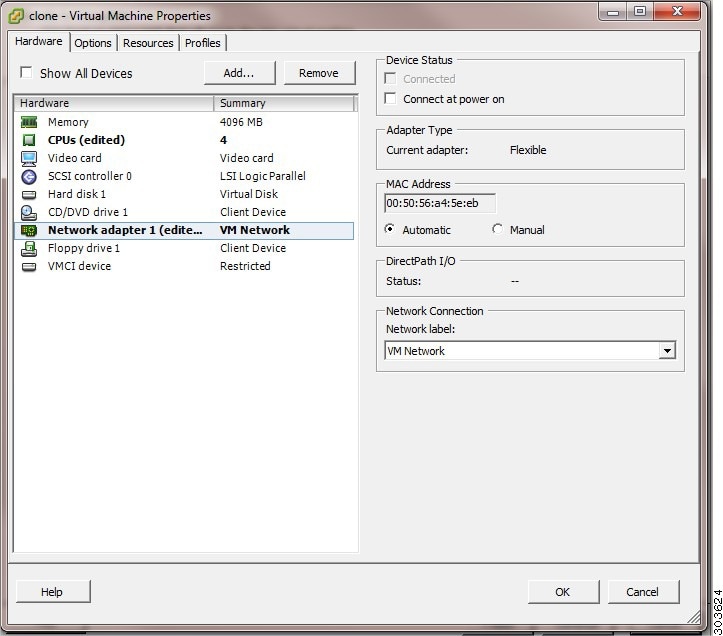
  • Ensure that the network adapter on the newly cloned Cisco ISE VM is not connected when you power on the machine. Uncheck the Connected and Connect at power on check boxes. Otherwise, if this node comes up, it will have the same IP address as the source machine from which it was cloned.

    Figure 2. Disconnecting the Network Adapter
    This image shows how to disconnect the network adaptor.
  • Ensure that you have the IP address and hostname that you are going to configure for the newly cloned VM as soon as you power on the machine. This IP address and hostname entry should be in the DNS server. You cannot use "localhost" as the hostname for a node.

  • Ensure that you have certificates for the Cisco ISE nodes based on the new IP address or hostname.

    Procedure
Procedure

Step 1

Right-click the newly cloned Cisco ISE VM and choose Power > Power On.

Step 2

Select the newly cloned Cisco ISE VM and click the Console tab.

Step 3

Enter the following commands on the Cisco ISE CLI:

configure terminal
hostname hostname

The hostname is the new hostname that you are going to configure. The Cisco ISE services are restarted.

Step 4

Enter the following commands:

interface gigabit 0
ip address ip_address netmask

The ip_address is the address that corresponds to the hostname that you entered in step 3 and netmask is the subnet mask of the ip_address. The system will prompt you to restart the Cisco ISE services. See the Cisco Identity Services Engine CLI Reference Guide, for the ip address and hostname commands.

Step 5

Enter Y to restart Cisco ISE services.


Connect a Cloned Cisco Virtual Machine to the Network

After you power on and change the ip address and hostname, you must connect the Cisco ISE node to the network.

Procedure

Step 1

Right-click the newly cloned Cisco ISE virtual machine (VM) and click Edit Settings.

Step 2

Click Network adapter in the Virtual Machine Properties dialog box.

Step 3

In the Device Status area, check the Connected and Connect at power on check boxes.

Step 4

Click OK.


Migrate Cisco ISE VM from Evaluation to Production

After evaluating the Cisco ISE release, you can migrate the from an evaluation system to a fully licensed production system.

Before you begin

  • When you move the VMware server to a production environment that supports a larger number of users, be sure to reconfigure the Cisco ISE installation to the recommended minimum disk size or higher (up to the allowed maximum of 2.4 TB).

  • Please not that you cannot migrate data to a production VM from a VM created with less than 300 GB of disk space. You can only migrate data from VMs created with 300 GB or more disk space to a production environment.

Procedure


Step 1

Back up the configuration of the evaluation version.

Step 2

Ensure that your production VM has the required amount of disk space.

Step 3

Install a production deployment license.

Step 4

Restore the configuration to the production system.


Check Virtual Machine Performance On-Demand

You can run the show tech-support command from the CLI to check the VM performance at any point of time. The output of this command will be similar to the following:

ise-vm123/admin# show tech | begin "disk IO perf"
Measuring disk IO performance
*****************************************
Average I/O bandwidth writing to disk device: 48 MB/second 
Average I/O bandwidth reading from disk device: 193 MB/second 
WARNING: VM I/O PERFORMANCE TESTS FAILED!
WARNING: The bandwidth writing to disk must be at least 50 MB/second,
WARNING: and bandwidth reading from disk must be at least 300 MB/second.
WARNING: This VM should not be used for production use until disk 
WARNING: performance issue is addressed. 
Disk I/O bandwidth filesystem test, writing 300 MB to /opt: 
314572800 bytes (315 MB) copied, 7.81502 s, 40.3 MB/s
Disk I/O bandwidth filesystem read test, reading 300 MB from /opt: 
314572800 bytes (315 MB) copied, 0.416897 s, 755 MB/s

Virtual Machine Resource Check from the Cisco ISE Boot Menu

You can check for virtual machine resources independent of Cisco ISE installation from the boot menu.

The CLI transcript appears as follows:


  Cisco ISE Installation (Serial Console)
  Cisco ISE Installation (Keyboard/Monitor)
  System Utilities (Serial Console)
  System Utilities (Keyboard/Monitor)

Use the arrow keys to select System Utilities (Serial Console) or System Utilities (Keyboard/Monitor) and press Enter. The following screen appears:


Available System Utilities:

  [1] Recover administrator password
  [2] Virtual Machine Resource Check
  [3] Perform System Erase
  [q] Quit and reload

Enter option [1 - 3] q to Quit

Enter 2 to check for VM resources. The output will be similar to the following:

*****
***** Virtual Machine host detected…
***** Hard disk(s) total size detected: 600 Gigabyte
***** Physical RAM size detected: 16267516 Kbytes
***** Number of network interfaces detected: 6
***** Number of CPU cores: 12
***** CPU Mhz: 2300.00
***** Verifying CPU requirement…
***** Verifying RAM requirement…
***** Writing disk partition table…

Linux KVM

KVM Virtualization Check

KVM virtualization requires virtualization support from the host processor; Intel VT-x for Intel processors and AMD-V for AMD processors. Open a terminal window on the host and enter the cat /proc/cpuinfo command. You must see either the vmx or the svm flag.

  • For Intel VT-x:
    # cat /proc/cpuinfo
    flags: fpu vme de pse tsc msr pae mce cx8 apic sep mtrr pge mca cmov pat pse36 clflush dts acpi mmx fxsr sse sse2 ss ht tm pbe syscall nx
    pdpe1gb rdtscp lm constant_tsc arch_perfmon pebs bts rep_good nopl xtopology nonstop_tsc aperfmperf eagerfpu pni pclmulqdq dtes64 monitor
    ds_cpl vmx smx est tm2 ssse3 cx16 xtpr pdcm pcid dca sse4_1 sse4_2 x2apic popcnt tsc_deadline_timer aes xsave avx lahf_lm arat epb xsaveopt
    pln pts dtherm tpr_shadow vnmi flexpriority ept vpid
  • For AMD-V:
    # cat /proc/cpuinfo
    flags: fpu tsc msr pae mce cx8 apic mtrr mca cmov pat pse36 clflush mmx fxsr sse sse2 ht syscall nx mmxext fxsr_opt rdtscp lm 3dnowext 3dnow
     pni cx16 lahf_lm cmp_legacy svm cr8_legacy

Install Cisco ISE on KVM

This procedure explains how to create a KVM on RHEL and install Cisco ISE on it using the Virtual Machine Manager (virt-manager).

If you choose to install Cisco ISE through the CLI, enter a command similar to the following one:

#virt-install --name= kvm-ise1  --arch=x86_64 --cpu=host --vcpus=2 --ram=4096 
--os-type=linux --os-variant=rhel6 --hvm --virt-type=kvm --cdrom= /home/admin/Desktop/ise-3.x.0.x.SPA.x86_64.iso  
--disk= /home/libvirt-images/kvm-ise1.img,size=300  
--network type=direct,model=virtio,source= eth2 ,source_mode=bridge 

where ise-3.x.0.x.SPA.x86_64.iso is the name of the Cisco ISE ISO image.

Before you begin

Download the Cisco ISE ISO image to your local system.

Procedure


Step 1

From the virt-manager, click New.

The Create a new virtual machine window appears.

Step 2

Click Local install media (ISO media or CDROM), and then click Forward.

Step 3

Click the Use ISO image radio button, click Browse, and select the ISO image from your local system.

  1. Uncheck the Automatically detect operating system based on install media check box, choose Linux as the OS type, choose supported Red Hat Enterprise Linux version, and click Forward.

Step 4

Choose the RAM and CPU settings and click Forward.

Step 5

Check the Enable storage for this virtual machine check box and choose the storage settings.

  1. Click the Select managed or other existing storage radio button.

  2. Click Browse.

  3. From the Storage Pools navigation pane on the left, click disk FileSystem Directory.

  4. Click New Volume.

    A Create storage volume window appears.

  5. Enter a name for the storage volume.

  6. Choose raw from the Format drop-down list.

  7. Enter the Maximum Capacity.

  8. Click Finish.

  9. Choose the volume that you created and click Choose Volume.

  10. Click Forward.

    The Ready to begin the installation screen appears.

Step 6

Check the Customize configuration before install check box.

Step 7

Under Advanced options, choose the macvtap as the source for the interface, choose Bridge in the Source mode drop-down list, and click Finish.

  1. (Optional) Click Add Hardware to add additional NICs.

    Choose macvtap as the Network source and virtio as the Device model.

  2. Click Finish.

Step 8

In the Virtual Machine screen, choose the disk device and under Advanced and Performance Options, choose the following options, and click Apply.

Field Value
Disk bus

VirtIO

Cache mode

none

IO mode

native

Step 9

Click Begin Installation to install Cisco ISE on KVM.

The Cisco ISE installation boot menu appears.

Step 10

At the system prompt, enter 1 to choose a monitor and keyboard port, or 2 to choose a console port, and press Enter.

The installer starts the installation of the Cisco ISE software on the VM. When the installation process finishes, the console displays:
Type 'setup' to configure your appliance
localhost:

Step 11

At the system prompt, type setup and press Enter.

The Setup Wizard appears and guides you through the initial configuration.


Note


You must add the following text to the VM settings XML file (under vcpu information) while installing Cisco ISE on Ubuntu Linux KVM. Otherwise, serial number will not be properly displayed in the About ISE and Server window:

<sysinfo type="smbios">
  <system>
    <entry name="product">KVM</entry>
  </system>
  <baseBoard>
    <entry name="product">KVM</entry>
  </baseBoard>
</sysinfo>
<OS>
  <type arch="x86_64" machine="pc-q35-6.2">hvm</type>
  <boot dev="hd"/>
  <smbios mode="sysinfo"/>
</os>

Microsoft Hyper-V

Create a Cisco ISE Virtual Machine on Hyper-V

This section describes how to create a new virtual machine, map the ISO image from the local disk to the virtual CD/DVD drive, edit the CPU settings, and install Cisco ISE on Hyper-V.


Note


Cisco ISE does not support the use of Multipath I/O (MPIO). Hence, the installation will fail if you are using MPIO for the VM.


Before you begin

Download the Cisco ISE ISO image from cisco.com to your local system.

Procedure


Step 1

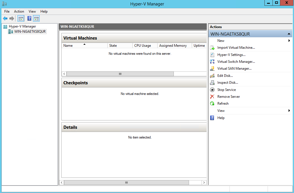
Launch Hyper-V Manager on a supported Windows server.

Figure 3. Hyper-V Manager Console
This image shows the Hyper-V Manager Console.

Step 2

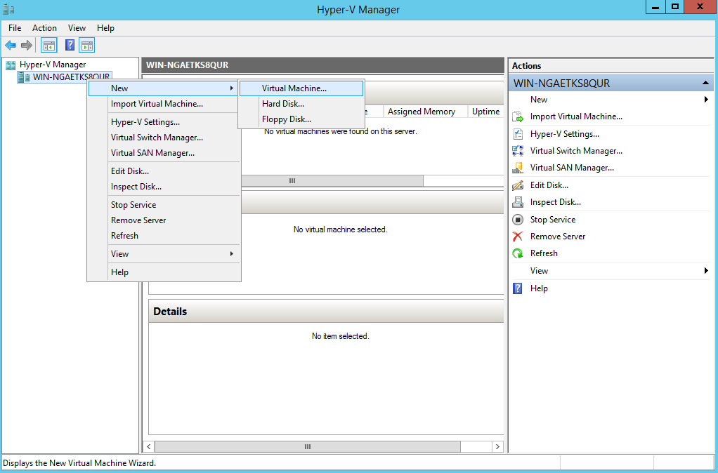
Right-click the VM host and click New > Virtual Machine.

Figure 4. Create New Virtual Machine
This image shows how to create a VM.

Step 3

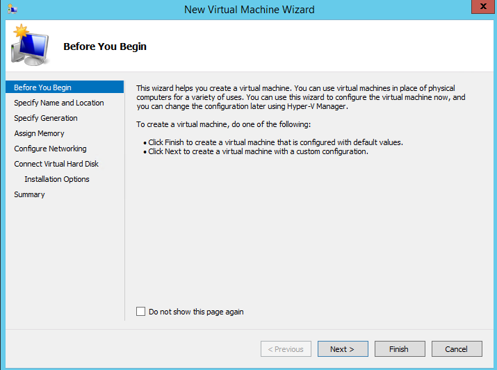
Click Next to customize the VM configuration.

Figure 5. New Virtual Machine Wizard
This image shows the New Virtal Machine Wizard

Step 4

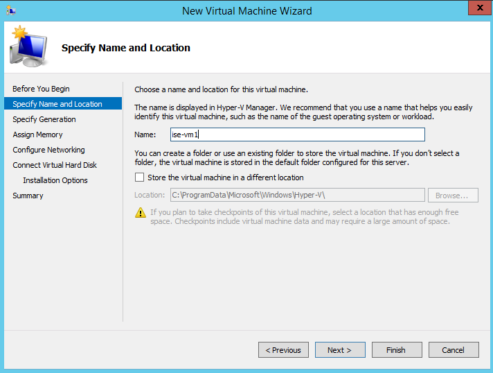
Enter a name for the VM and (optionally) choose a different path to store the VM, and click Next.

Figure 6. Specify Name and Location
Specify name and location for the virtual machine.

Step 5

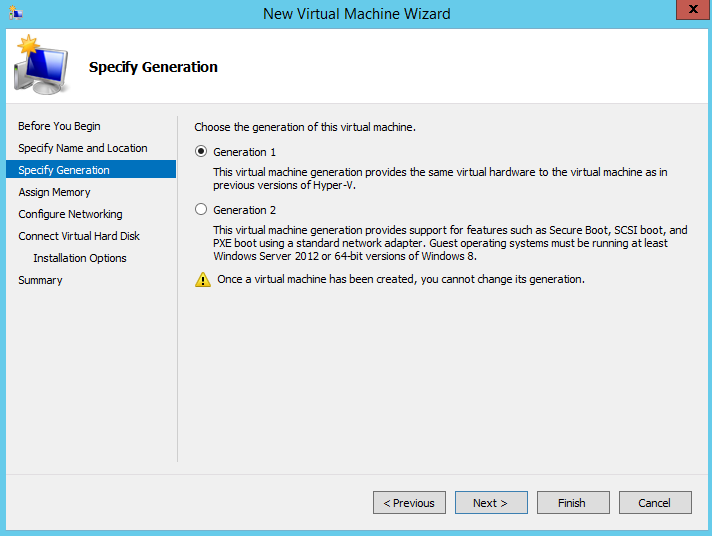
Click the Generation 1 radio button and click Next.

If you choose to create a Generation 2 ISE VM, ensure that you disable the Secure Boot option in the VM settings.

Figure 7. Specify Generation
Choose the generation for the virtual machine.

Step 6

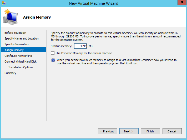
Specify the amount of memory to allocate to this VM, for example, 16000 MB, and click Next.

Figure 8. Assign Memory
Assign memory for the virtual machine.

Step 7

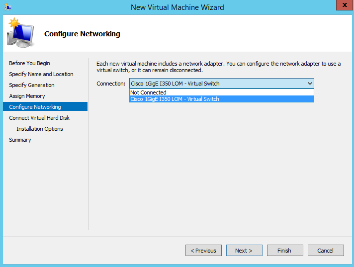
Select the network adapter and click Next.

Figure 9. Configure Networking
Configure networking for the virtual machine.

Step 8

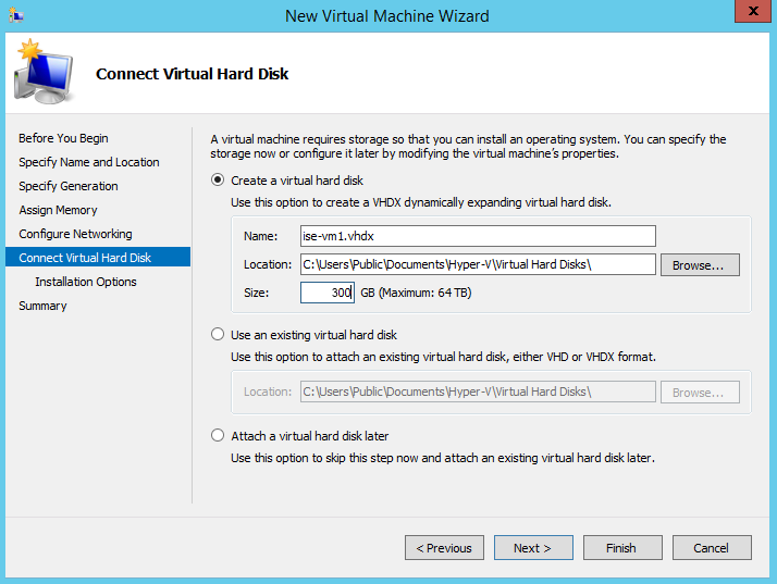
Click the Create a virtual hard disk radio button and click Next.

Figure 10. Connect Virtual Hard Disk
Connect virtual hard disk to the virtual machine.

Step 9

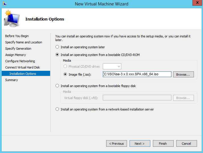
Click the Install an operating system from a bootable CD/DVD-ROM radio button.

  1. From the Media area, click the Image file (.iso) radio button.

  2. Click Browse to select the ISE ISO image from the local system and click Next.

Figure 11. Installation Options
Installation options for the virtual machine.

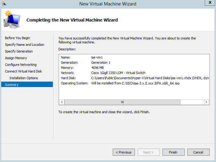
Step 10

Click Finish.

Figure 12. Complete the New Virtual Machine Wizard
Finishing the New Virtual Machine Wizard.

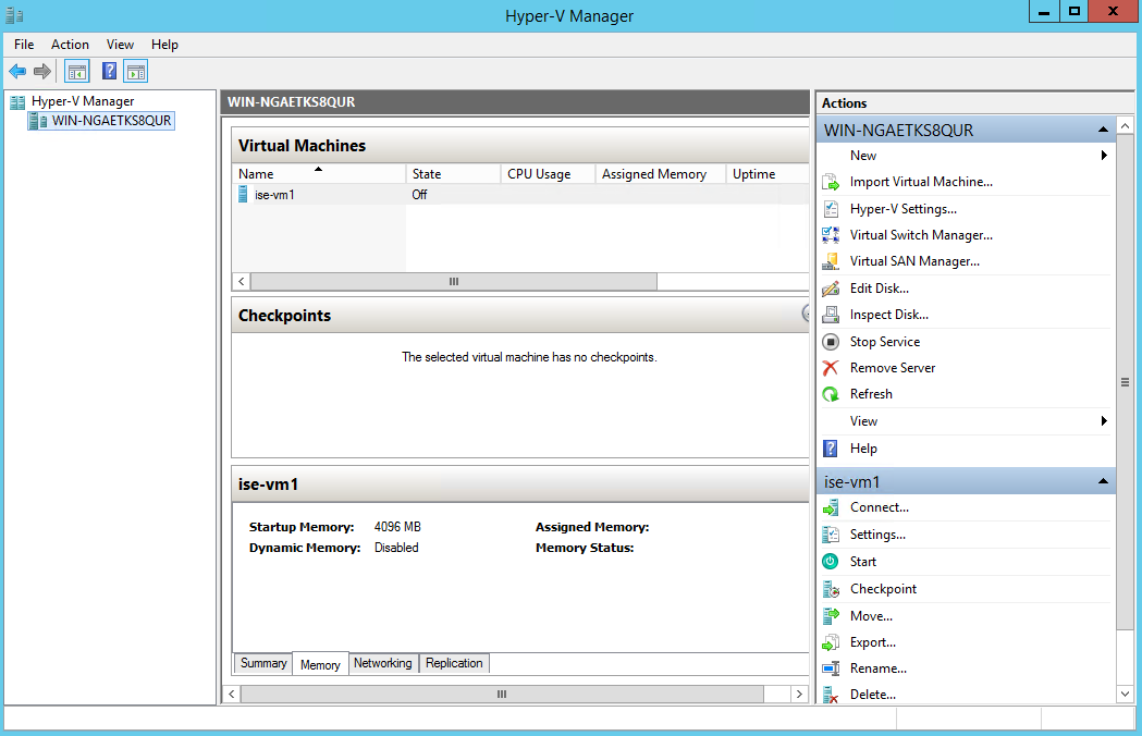
The Cisco ISE VM is created on Hyper-V.

Figure 13. New Virtual Machine created
New Virtual Machine created.

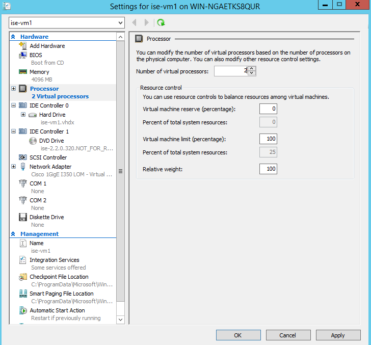
Step 11

Select the VM and edit the VM settings.

  1. Select Processor. Enter the number of virtual processors, for example, 6, and click OK.

    Figure 14. Edit VM Settings
    Edit virtual machine settings.

Step 12

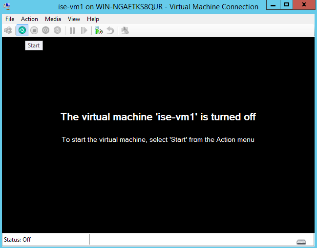
Select the VM and click Connect to launch the VM console. Click the start button to turn on the Cisco ISE VM.

Figure 15. Start the Cisco ISE VM
Start the virtual machine.

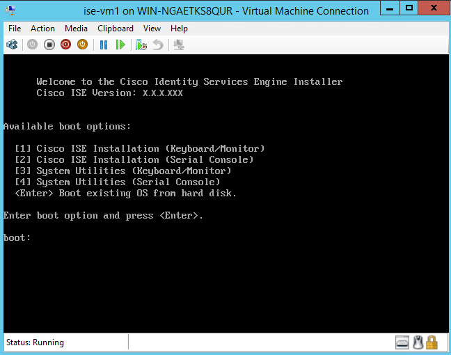
The Cisco ISE installation menu appears.

Figure 16. CIsco ISE installation menu
Virtual Machine installation menu.

Step 13

Enter 1 to install Cisco ISE using a keyboard and monitor.


Zero Touch Provisioning

Zero Touch Provisioning (ZTP) is an uninterrupted provisioning mechanism that automates Cisco ISE installation, patching, hot patching, and infrastructure service enablement without manual intervention.

ZTP is available from Cisco ISE Release 3.1 onwards. There are two options available in ZTP:

  • Mapping .img file: This method is supported in virtual machine (VM) automatic installations, appliances, and OVA installations. It requires mandatory parameters such as hostname, IP address, IP netmask, IP default gateway, DNS domain, primary name server, NTP server, system timezone, SSH, username, and password to be configured. Optional parameters such as IPV6, patch, hot patch, services, and repository details can also be configured. For more information, see ZTP Configuration Image File.


    Note


    You cannot use an .img file for ZTP on Microsoft Hyper-V. You must use an .iso file and create a Generation 2 VM for ZTP on Microsoft Hyper-V.


  • VM User Data: This method is supported in OVA and VM automatic installations. It is supported when the user data is configured and requires mandatory parameters such as hostname, IP address, IP netmask, IP default gateway, DNS domain, primary name server, NTP server, system timezone, SSH, username, and password to be configured. Optional parameters such as IPV6, patch, hot patch, services, and repository details can also be configured. For more information, see VM User Data.


Note


  • To track installation progress during the ZTP process, the serial console should be enabled for both the VM and the appliance.

  • A ZTP Configuration Image File is required.


If you provision Cisco ISE through ZTP, the following two security features are available:


Note


TFTP, HTTP, HTTPS, and NFS repositories are supported for installation of hot patches and patches on Cisco ISE as part of the ZTP flow. The repositories created during the ZTP flow will not be visible or usable from the Cisco ISE GUI. These repositories must have anonymous access (no username/password) for the ZTP process to use them.


Configure Public Key Authentication

Users are now able to be authenticated using public key authentication, when adding the public key to the ZTP configuration file. When authentication using public key is enabled, password-based user authentication is disabled. The public key authentication mechanism can be disabled at any time.

To revert back to password-based authentication use the following command in the Cisco ISE CLI:
conf t
no service sshd PubkeyAuthentication
For more information about this command, see the section "Service" in the Chapter "Cisco ISE CLI Commands in Configuration Mode" in the Cisco Identity Services Engine CLI Reference Guide for your Cisco ISE release.

Note


Do not execute the command service sshd PubkeyAuthentication if you have not included the public key in the ZTP configuration image file before installation. This disables password-based authentication and Cisco ISE will expect you to login using a private key. If you do run into this issue, you need to use the console port to login into Cisco ISE and revert the configuration.


Procedure


Step 1

Generate a public and private RSA key pair using a third-party application.

Step 2

Include the public key that is generated in the ZTP configuration image file.

Step 3

Install Cisco ISE using ZTP.

Step 4

Log in to the CLI of Cisco ISE using the private key that is generated, using the following command:

ssh -i <path to private key> <username>@<ise-ip>

You can now successfully log in to the CLI of Cisco ISE using your private key.

First Login Password Change

When logging in to the Cisco ISE GUI for the first time, after the successful installation of Cisco ISE using ZTP, you are prompted to reset the password. This is because the password is specified in plain text in the ZTP configuration image file. This feature is enabled by default when installing Cisco ISE through ZTP.

Automatic Installation in Virtual Machine

The following subsections provide information about automatic installation in the VM.

These settings are applicable for all on-prem hypervisors:

  • VMware

  • Linux KVM

  • Microsoft Hyper-V

  • Nutanix AHV

Automatic Installation in Virtual Machine Using the ZTP Configuration Image File

Procedure

Step 1

Log in to the VMware client.

Note


If you already have an existing VM setup, proceed to Step 2 and continue till Step 6. For a new VM setup, go directly to Step 8.

Step 2

For the VM to enter the BIOS setup mode, right-click the VM and select Edit Settings.

Step 3

Click the Options tab.

Step 4

Click Boot Options.

Step 5

In the Force BIOS Setup area, check the BIOS check box to enter the BIOS setup screen when the VM boots.

Note


You must change the firmware from BIOS to EFI in the the boot mode of VM settings in order to boot GPT partitions with 2 TB or more capacity.

Step 6

Click OK.

Step 7

Ensure that the time zone and the correct boot order are set in BIOS/EFI:

  1. If the VM is turned on, turn the system off.

  2. Turn on the VM.

    The system enters the BIOS setup mode.

  3. In the main BIOS menu, using the arrow keys, navigate to the Date and Time field and press Enter.

  4. Enter the time zone.

    This time zone setting ensures that the reports, logs, and posture-agent log files from the various nodes in your deployment are always synchronized with regard to the time stamps.

  5. Using the arrow keys, navigate to the boot menu and press Enter.

  6. Using the arrow keys, select the CD-ROM drive and press + to move the CD-ROM drive up the order.

  7. Using the arrow keys, navigate to the Exit menu and choose Exit Saving Changes. (Press the Enter or Return key to select your choice).

  8. Choose Yes to save the changes and exit.

Step 8

Insert the Cisco ISE software DVD into the VMware ESXi host's primary CD/DVD drive.

Step 9

Insert the ZTP configuration image file into a secondary CD/DVD drive.

Step 10

Turn on the VM.

When the DVD starts, the console displays the following message:


Automatic installation starts in 150 seconds.
Available boot options:
[1] Cisco ISE Installation (Keyboard/Monitor)
[2] Cisco ISE Installation (Serial Console)
[3] System Utilities (Keyboard/Monitor)
[4] System Utilities (Serial Console)
[5] Hard Disk
Enter boot option and press <Enter>.
boot: 

Note


From Cisco ISE 3.1 onwards, pressing Enter without entering a boot option does not trigger the installation using the hard disk option. Instead it triggers ZTP.

Step 11

After 150 seconds, the bootup process automatically starts if the prerequisites are met.

Note

 
  • Installation logs can be monitored only through the serial console because ZTP only works through the serial console. It can be monitored from the VM console after the setup prompt is displayed.

  • After the Cisco ISE services are started, you must manually unmount the ZTP configuration image file from the CD/DVD.

To leverage ZTP from the setup prompt (ZTP is carried out using the keyboard until the setup prompt apprears) perform this procedure:

1. Install Cisco ISE manually till setup (using boot option 1 or 2) and create the ZTP configuration image file using the steps described in the above procedure.

2. Power off the VM and map the ZTP configuration image file to the CD/DVD drive.

3. Power on the VM.

The setup details are picked up from the ZTP configuration file that is mapped to the CD/DVD drive.


Troubleshooting

Issue: If the automatic installation in the VM is triggered without mapping the .img file, after 150 seconds, the installation fails with the following message:


***** The ZTP configuration image is missing or improper. Automatic installation flow
 exited.
***** Power off and attach the proper ZTP configuration image or choose manual boot to
 proceed.

Solution: This error message is seen only through the serial console and not on the VM console. If this happens in an existing VM where Cisco ISE is already installed, the hard disk will not be formatted at this state. The existing VM can be recovered by performing these steps: :

1. Turning off the VM.

2. Turning on the VM.

3. Pressing option 5 to boot from hard disk within 150 seconds to load the existing VM.

Issue: If the setup details are invalid in the configuration file, ZTP installation is stopped and the following message is displayed on the VM Console:
==============================================================================

Cisco ISE Installation Failed

==============================================================================

Error: Sync with NTP server failed.

Check the setup details in your configuration image and reboot Cisco ISE

with proper ZTP configuration.

==============================================================================

Solution:

1. Create a new configuration .img file with valid details.

2. Power off the VM.

3. Map the new valid image to the CD/DVD drive.

4. Power on the VM.

Installation begins from the setup.

Automatic Installation in Virtual Machine using VM User Data

Procedure

Step 1

Log in to the VMware client.

Note


If you already have an existing VM setup, proceed to Step 2 and continue till Step 6. For a new VM setup, go directly to Step 8.

Step 2

For the VM to enter the BIOS setup mode, right-click the VM and select Edit Settings.

Step 3

Click the Options tab.

Step 4

Click Boot Options.

Step 5

In the Force BIOS Setup area, check the BIOS check box to enter the BIOS setup screen when the VM boots.

Note


You must change the firmware from BIOS to EFI in the the boot mode of VM settings in order to boot GPT partitions with 2 TB or more capacity.

Step 6

Click OK.

Step 7

Ensure that the time zone and the correct boot order are set in BIOS/EFI:

  1. If the VM is turned on, turn the system off.

  2. Turn on the VM.

    The system enters the BIOS setup mode.

  3. In the main BIOS menu, using the arrow keys, navigate to the Date and Time field and press Enter.

  4. Enter the time zone.

    This time zone setting ensures that the reports, logs, and posture-agent log files from the various nodes in your deployment are always synchronized with regard to the time stamps.

  5. Using the arrow keys, navigate to the boot menu and press Enter.

  6. Using the arrow keys, select the CD-ROM drive and press + to move the CD-ROM drive up the order.

  7. Using the arrow keys, navigate to the Exit menu and choose Exit Saving Changes (Press the Enter or Return key to select your choice).

  8. Choose Yes to save the changes and exit.

Step 8

Insert the Cisco ISE software DVD into the VMware ESXi host's primary CD/DVD drive.

Step 9

Configure the VM user data options.

Note


If both the .img file and VM user data options are configured in the VM, the user data option is considered.

Step 10

Turn on the VM.

When the DVD boots, the console displays the following message:


Automatic installation starts in 150 seconds.
Available boot options:
[1] Cisco ISE Installation (Keyboard/Monitor)
[2] Cisco ISE Installation (Serial Console)
[3] System Utilities (Keyboard/Monitor)
[4] System Utilities (Serial Console)
[5] Hard Disk
Enter boot option and press <Enter>.
boot: 

Note


From Cisco ISE 3.1 onwards, pressing Enter without entering a boot option does not trigger the installation using the hard disk option. Instead it triggers ZTP.

Step 11

After 150 seconds, the bootup process automatically starts if the prerequisites are met.

Note

 
  • Installation logs can be monitored only through the serial console because ZTP works only through the serial console. It can be monitored from the VM console after the setup prompt is displayed.

  • After the Cisco ISE services are started, you must manually unmount the ZTP configuration image file from the CD/DVD.

To leverage ZTP from the setup prompt (ZTP is carried out using the keyboard until the setup prompt apprears) perform this procedure:

1. Power off the VM.

2. Configure user-data option mentioned above.

3. Power on the VM .

The setup details are picked from the VM options.


Troubleshooting

Issue: If invalid setup details are entered in the user data option, the ZTP installation stops and the following message is displayed on the VM console:
==============================================================================

Cisco ISE Installation Failed

==============================================================================

Error: Sync with NTP server failed.

Check the setup details in your configuration image and reboot Cisco ISE

with proper ZTP configuration.

==============================================================================

Solution:

1. Power off the VM.

2. Update user data details with valid data.

3. Power on the VM.

Installation begins from the setup.

Automatic Installation in Appliance

The following subsections provide information about automatic installation in an appliance.

Automatic Installation in Appliance Using the ZTP Configuration Image File

Procedure

Step 1

Log in to the SNS Appliance.

Step 2

Power off the host.

Step 3

Choose Compute > Remote Management > Virtual media.

Step 4

Map the Cisco ISE software ISO and the ZTP configuration image file to the primary CD/DVD drive and the secondary CD/DVD drive.

Step 5

Power on the host.

When the appliance boots, the console displays the following message:


Please select boot device:
[1] Cisco ISE Installation (Keyboard/Monitor)
[2] Cisco ISE Installation (Serial Console)
[3] System Utilities (Keyboard/Monitor)
[4] System Utilities (Serial Console)
[5] Cisco ISE Installation Through ZTP Configuration (Serial Console)

Step 6

After 150 seconds, the start process automatically starts if the prerequisites are met.

Note

 
  • ZTP works on the SNS appliance through virtual media only.

  • You must map the .img file in virtual media before mapping the ISO file.

    Installation logs can be monitored through only the serial console because ZTP works through the serial console. The logs can be monitored from the KVM console after the setup prompt is displayed.

  • Automatic installation in appliance is supported only with the .img file.

To leverage ZTP from the setup prompt (ZTP is done using the keyboard until the setup prompt apprears) perform the following steps:

1. Install Cisco ISE manually till setup (using boot option 1 or 2) and create the ZTP configuration image file using the steps described in the previous above.

2. Power off the host and map the ZTP configuration image file that is created, to the CD/DVD drive.

3. Power on the host.

The setup details are picked from the ZTP configuration file that is mapped to the CD/DVD drive.


Troubleshooting

Issue: If the automatic installation in the appliance is triggered without mapping the image file, after 150 seconds, the installation fails with the following message:


***** The ZTP configuration image is missing or improper. Automatic installation flow
 exited.
***** Power off and attach the proper ZTP configuration image or choose manual boot to
 proceed.

Solution:

1. Turn off the VM.

2. Turn on the VM.

3. Press option 5 to boot from hard disk within 150 seconds to load the existing VM.

Issue: If the setup details are invalid in the config file, ZTP installation is stopped and the following message is displayed on the KVM console:
==============================================================================

Cisco ISE Installation Failed

==============================================================================

Error: Sync with NTP server failed.

Check the setup details in your configuration image and reboot Cisco ISE

with proper ZTP configuration.

==============================================================================

Solution:

1. Create a new configuration .img file with valid details.

2. Power off the VM.

3. Map the new valid image to the CD/DVD drive.

4. Power on the VM.

Installation begins from the setup.

Trigger Automatic Installation using UCS XML APIs

To trigger automatic installation:


Note


The API URL and the request header are the same for all the methods:


API URL
https://<ucs_server_ip>/nuova 

Header

 headers["Accept"] = "application/xml" 
headers["Content-Type"] = "application/xml"
Procedure

Step 1

Get the login session cookie for authentication.

The aaaLogin method is the login process and is required to begin a session. This action establishes the HTTP (or HTTPS) session between the client and Cisco IMC. This session cookie is used in upcoming requests to maintain the login session.

Request

<aaaLogin inName='admin' inPassword='password'/>

Response

<aaaLogin cookie="" response="yes" outCookie="<real_cookie>" outRefreshPeriod="600" outPriv="admin" outSessionId="17" outVersion="3.0(0.149)"> </aaaLogin>

Step 2

Map the Cisco ISE ISO.

This configures a Cisco ISE ISO file as a virtual media volume.

Request

<configConfMo cookie='<real_cookie>' dn='sys/svc-ext/vmedia-svc/vmmap-ISE_ISO' inHierarchical='false'>
<inConfig>
<commVMediaMap dn='sys/svc-ext/vmedia-svc/vmmap-ISE_ISO' 
 map=’nfs’ 
 remoteFile=‘<ise_iso_file>’ 
 remoteShare=‘<nfs_server_path>' 
 status='created' volumeName='ISE_ISO' />
</inConfig>
</configConfMo>

Response

<configConfMo dn="sys/svc-ext/vmedia-svc/vmmap-ISE_ISO" 
 cookie="<real_cookie>" response="yes">
<outConfig>
 <commVMediaMap volumeName="ISE_ISO" map=“nfs” 
  remoteShare=‘<nfs_server_path>' 
  remoteFile="<ise_iso_file>" 
  mappingStatus="In Progress"
  dn="sys/svc-ext/vmedia-svc/vmmap-ISE_ISO" status="created"/>
  </outConfig>
</configConfMo>

Step 3

Map the configuration image file.

This configures a configuration image as a vMedia volume.

Request

<configConfMo cookie='<real_cookie>' 
dn='sys/svc-ext/vmedia-svc/vmmap-CONFIG-IMG’ inHierarchical='false'>
<inConfig>
<commVMediaMap dn='sys/svc-ext/vmedia-svc/vmmap-CONFIG-IMG' 
  map=’nfs’ 
  remoteFile=‘<config_img_file>’ 
  remoteShare=‘<nfs_server_path>' 
  status='created' volumeName='CONFIG-IMG' />
</inConfig>
</configConfMo>

Response

<configConfMo dn="sys/svc-ext/vmedia-svc/vmmap-CONFIG-IMG" 
 cookie="<real_cookie>" response="yes">
<outConfig>
 <commVMediaMap volumeName="CONFIG-IMG" map=“nfs” 
  remoteShare=‘<nfs_server_path>' 
  remoteFile="<config_img_file>" 
  mappingStatus="In Progress"
  dn="sys/svc-ext/vmedia-svc/vmmap-CONFIG-IMG" status="created"/>
  </outConfig>
</configConfMo>

Step 4

Set the CD-ROM at first place in the boot order.

This maps the Cisco ISE ISO file that is picked for installation during the power restart.

Request

<configConfMo cookie="<real_cookie>" 
inHierarchical="true" dn="sys/rack-unit-1/boot-policy">
  <inConfig>
    <lsbootDef dn="sys/rack-unit-1/boot-policy"  rebootOnUpdate=“yes”>
      <lsbootVirtualMedia access="read-only" order=“1” dn="sys/rack-unit-1/boot-policy/vm-read-only"/>
     </lsbootDef>
  </inConfig>
</configConfMo>

Response

<configConfMo dn="sys/rack-unit-1/boot-policy" cookie="<real_cookie>" response="yes">
<outConfig>
  <lsbootDef dn="sys/rack-unit-1/boot-policy" name="boot-policy" purpose="operational" rebootOnUpdate="no" status="modified" >
  </lsbootDef>
</outConfig>
</configConfMo>

Step 5

Enable the SoL (Serial over LAN).

This enables the SoL to view installation logs through Telnet.

Request

<configConfMo cookie='<real_cookie>' 
dn='sys/rack-unit-1/sol-if'>
<inConfig>
  <solIf dn='sys/rack-unit-1/sol-if' adminState=‘enable'/>
 </inConfig>
</configConfMo>

Response

<configConfMo dn="sys/rack-unit-1/sol-if" cookie="<real_cookie>" response="yes">
<outConfig>
<solIf dn="sys/rack-unit-1/sol-if" adminState="enable" name="SoLInterface" speed="115200" comport="com0" sshPort="2400" status="modified" ></solIf></outConfig>
</configConfMo>

Step 6

Power restart.

This triggers Cisco ISE installation in automatic mode.

Request

<configConfMo cookie='<real_cookie>' dn='sys/rack-unit-1'>
<inConfig><computeRackUnit
dn='sys/rack-unit-1' 
adminPower='cycle-immediate'/>
</inConfig>
</configConfMo>

Response

<configConfMo dn="sys/rack-unit-1" cookie="<real_cookie>" response="yes">
<outConfig>
   <computeRackUnit dn="sys/rack-unit-1" adminPower="policy" availableMemory="262144" model="SNS-3695-K9" memorySpeed="2400" name="SNS-3695-K9" numOfAdaptors="0" numOfCores="12" numOfCoresEnabled="12" numOfCpus="1" numOfEthHostIfs="0" numOfFcHostIfs="0" numOfThreads="24" operPower="on" originalUuid="1935836B-B968-4031-8A98-7984F1D35449" presence="equipped" serverId="1" serial="WZP2228085W" totalMemory="262144" usrLbl="" uuid="1935836B-B968-4031-8A98-7984F1D35449" vendor="Cisco Systems Inc" cimcResetReason="graceful-reboot
" assetTag="Unknown" adaptorSecureUpdate="Enabled" resetComponents="components" storageResetStatus="NA" vicResetStatus="NA" bmcResetStatus="NA" smartUsbAccess="disabled" smartUsbStatus="Disabled" biosPostState="completed" status="modified" >
  </computeRackUnit>
</outConfig>
</configConfMo>

Step 7

Logout to exit the session.

Request

<aaaLogout
    cookie="<real_cookie>"
    inCookie="<real_cookie>"
</aaaLogout>

Response:

<aaaLogout cookie="" response="yes" outStatus="success"> </aaaLogout>

For more information, see UCS API methods.


OVA Automatic Installation

The following sections provide information about automatic installation using the OVA.

Automatic OVA Installation Using the ZTP Configuration Image File

Procedure

Step 1

Log in to the VMware client.

Note


If you already have an existing VM setup, proceed to Step 2 and continue till Step 6. For a new VM setup, go directly to Step 8.

Step 2

For the VM to enter the BIOS setup mode, right-click the VM and select Edit Settings.

Step 3

Click the Options tab.

Step 4

Click Boot Options.

Step 5

In the Force BIOS Setup area, check the BIOS check box to enter the BIOS setup screen when the VM boots.

Note


You must change the firmware from BIOS to EFI in the the boot mode of VM settings in order to boot GPT partitions with 2 TB or more capacity.

Step 6

Click OK.

Step 7

Ensure that the Coordinated Universal Time (UTC) and the correct boot order are set in BIOS:

  1. If the VM is turned on, turn the system off.

  2. Turn on the VM.

    The system enters the BIOS setup mode.

  3. In the main BIOS menu, using the arrow keys, navigate to the Date and Time field and press Enter.

  4. Enter the UTC/Greenwich Mean Time (GMT) time zone.

    This time zone setting ensures that the reports, logs, and posture-agent log files from the various nodes in your deployment are always synchronized with regard to the time stamps.

  5. Using the arrow keys, navigate to the boot menu and press Enter.

  6. Using the arrow keys, select the CD-ROM drive and press + to move the CD-ROM drive up the order.

  7. Using the arrow keys, navigate to the Exit menu and choose Exit Saving Changes (Press the Enter or Return key to select your choice).

  8. Choose Yes to save the changes and exit.

Step 8

Import the Cisco ISE OVA file into the VMware ESXi.

Step 9

Insert the ZTP configuration image file into the VMware ESXi host's primary CD/DVD drive.

Step 10

Turn on the virtual machine.

When the DVD boots, the console displays the following message:


Automatic installation starts in 150 seconds.
Available boot options:
[1] Cisco ISE Installation (Keyboard/Monitor)
[2] Cisco ISE Installation (Serial Console)
[3] System Utilities (Keyboard/Monitor)
[4] System Utilities (Serial Console)
[5] Hard Disk
Enter boot option and press <Enter>.
boot: 

Note


From Cisco ISE 3.1 onwards, pressing Enter without entering a boot option does not trigger the installation using the hard disk option. Instead it triggers ZTP.

Step 11

After 150 seconds, the bootup process automatically starts if the prerequisites are met.

Note

 
  • Installation logs can be monitored only through the serial console because ZTP works only through the serial console. The logs can be monitored from the VM console after the setup prompt is displayed.

  • After the Cisco ISE services are started, you must manually unmount the ZTP configuration image file from the CD/DVD.

To leverage ZTP from the setup prompt (ZTP is done using the keyboard until the setup prompt apprears) perform this procedure:

1. Install Cisco ISE manually till setup (using boot option 1 or 2) and create the ZTP configuration image file using the steps described in the above procedure.

2. Power off the VM.

3. Map the ZTP configuration image file to the CD/DVD drive.

4. Power on the VM.

The setup details are picked up from the ZTP configuration file that is mapped to the CD/DVD drive.


Troubleshooting

Issue: If the setup details are invalid in the configuration file, ZTP installation stops and the following message is displayed on the VM console:

==============================================================================

Cisco ISE Installation Failed

==============================================================================

Error: Sync with NTP server failed.

Check the setup details in your configuration image and reboot Cisco ISE

with proper ZTP configuration.

==============================================================================

Solution: This can be resolved by performing the following steps:

1. Create a new configuration .img file with valid details.

2. Power off the VM.

3. Map the new valid image to the CD/DVD drive.

4. Power on the VM.

Installation begins from the setup.

OVA Automatic Installation Using the VM User Data

Procedure

Step 1

Log in to the VMware client.

Note


If you already have an existing VM setup, proceed to Step 2 and continue till Step 6. For a new VM setup, go directly to Step 8.

Step 2

For the VM to enter the BIOS setup mode, right-click the VM and select Edit Settings.

Step 3

Click the Options tab.

Step 4

Click Boot Options.

Step 5

In the Force BIOS Setup area, check the BIOS check box to enter the BIOS setup screen when the VM boots.

Note


You must change the firmware from BIOS to EFI in the the boot mode of VM settings in order to boot GPT partitions with 2 TB or more capacity.

Step 6

Click OK.

Step 7

Ensure that the Coordinated Universal Time (UTC) and the correct boot order are set in BIOS:

  1. If the VM is turned on, turn the system off.

  2. Turn on the VM.

    The system enters the BIOS setup mode.

  3. In the main BIOS menu, using the arrow keys, navigate to the Date and Time field and press Enter.

  4. Enter the UTC/Greenwich Mean Time (GMT) time zone.

    This time zone setting ensures that the reports, logs, and posture-agent log files from the various nodes in your deployment are always synchronized with regard to the time stamps.

  5. Using the arrow keys, navigate to the boot menu and press Enter.

  6. Using the arrow keys, select the CD-ROM drive and press + to move the CD-ROM drive up the order.

  7. Using the arrow keys, navigate to the Exit menu and choose Exit Saving Changes (Press the Enter or Return key to select your choice).

  8. Choose Yes to save the changes and exit.

Step 8

Import the Cisco ISE OVA file into the VMware ESXi.

Step 9

Configure the VM user data options.

Note


If both .img file and VM user data options are configured in the VM, the user data option is considered.

Step 10

Turn on the VM.

When the DVD boots, the console displays the following message:


Automatic installation starts in 150 seconds.
Available boot options:
[1] Cisco ISE Installation (Keyboard/Monitor)
[2] Cisco ISE Installation (Serial Console)
[3] System Utilities (Keyboard/Monitor)
[4] System Utilities (Serial Console)
[5] Hard Disk
Enter boot option and press <Enter>.
boot: 

Note


From Cisco ISE 3.1 onwards, pressing Enter without entering a boot option does not trigger the installation using the hard disk option. Instead it triggers ZTP.

Step 11

After 150 seconds, the bootup process automatically starts if the prerequisites are met.

Note

 
  • Installation logs can be monitored only through the serial console because ZTP works only through the serial console. It can be monitored from the VM console after the setup prompt is displayed.

  • After the Cisco ISE services are started, you must manually unmount the ZTP configuration image file from the CD/DVD.

To leverage ZTP from the setup prompt (ZTP is carried out using the keyboard until the setup prompt apprears) perform this procedure:

1. Power off the VM.

2. Configure user-data option mentioned above.

3. Power on the VM .

The setup details are picked from the VM options.


Troubleshooting

Issue: If invalid setup details are entered in the user data option, the ZTP installation stops and the following message is displayed on the VM console:
==============================================================================

Cisco ISE Installation Failed

==============================================================================

Error: Sync with NTP server failed.

Check the setup details in your configuration image and reboot Cisco ISE

with proper ZTP configuration.

==============================================================================

Solution: This can be resolved by performing the following steps:

1. Power off the VM.

2. Update user data details with valid data.

3. Power on the VM.

Installation begins from the setup.

Creating the ZTP Configuration Image File

Create the ZTP configuration image file using the ./create_ztp_image.sh ise-ztp.conf ise-ztp.img command. The script can be executed on RHEL, CentOS, or Ubuntu.

To skip the ICMP, DNS, and NTP checks, set the following flags to True in the configuration image file:

  • ICMP: SkipIcmpChecks=true

  • DNS: SkipDnsChecks=true

  • NTP: SkipNtpChecks=true


Note


The default values for these flags is false which means by default, during the ZTP installation the above checks will be made if not explicitly mentioned in the configuration file.


create_ztp_image.sh script creation

#!/bin/bash
###########################################################
# This script is used to generate ise ztp image with ztp
# configuration file.
#
# Need to pass ztp configuration file as input.
#
# Copyright (c) 2021 by Cisco Systems, Inc.
# All rights reserved.
# Note:
# To mount the image use below command
# mount ise_ztp_config.img /ztp
# To mount the image from cdrom
# mount -o ro /dev/sr1 /ztp
#############################################################
if [ -z "$1" ];then
echo "Usage:$0 <ise-ztp.conf> [out-ztp.img]"
exit 1
elif [ ! -f $1 ];then
echo "file $1 not exist"
exit 1
else
conf_file=$1
fi
if [ -z "$2" ] ;then
image=ise_config.img
else
image=$2
fi
mountpath=/tmp/ise_ztp
ztplabel=ISE-ZTP
rm -fr $mountpath
mkdir -p $mountpath
dd if=/dev/zero of=$image bs=1k count=1440 > /dev/null 2>&1
if [ `echo $?` -ne 0 ];then
echo "Image creation failed\n"
exit 1
fi
mkfs.ext4 $image -L $ztplabel -F > /dev/null 2>&1
mount -o rw,loop $image $mountpath
cp $conf_file $mountpath/ise-ztp.conf
sync
umount $mountpath
sleep 1
# Check for automount and unmount
automountpath=$(mount | grep $ztplabel | awk '{print $3}')
if [ -n "$automountpath" ];then
umount $automountpath
fi
echo "Image created $image"

VM User Data

VM user data is supported from ESXi 6.5 and later for Cisco ISE installation.

Paste the content of the ise-ztp.conf file in the base64encode tool. Use the base64encode tool to get the encoded string.

You have to enter the encoded base64 string in the VM along with the VM user data. In the VMware ESXi, go to VM Options > Advanced > Configuration Parameters > Edit Configuration > guestinfo.ise.ztp = [Value] Base Encoded ZTP Configuration to enter the string.


Note


While configuring ZTP for deploying a patch or hot patch, you must use http (lower case) instead of HTTP. Otherwise, the patch files cannot be downloaded from the repository.