Camera Installation
This chapter provides information and instructions for installing the Cisco Video Surveillance 3520 IP Camera, and includes the following topics:
Installation Guidelines
This section describes how to install the IP camera. Before installing, review these guidelines:
•![]() The IP camera requires a network cable and a connection to a standard 10/100BaseT router or switch. To power the IP camera with Power over Ethernet (PoE), a switch must be 802.3af compliant.
The IP camera requires a network cable and a connection to a standard 10/100BaseT router or switch. To power the IP camera with Power over Ethernet (PoE), a switch must be 802.3af compliant.
•![]() If you are using the IP camera on a network connection that does not provide PoE, you must use a Cisco 12 VDC power adapter (Cisco part number CIVS-PWRPAC-12V) or a third-party 24 VAC power adapter.
If you are using the IP camera on a network connection that does not provide PoE, you must use a Cisco 12 VDC power adapter (Cisco part number CIVS-PWRPAC-12V) or a third-party 24 VAC power adapter.
•![]() If you are using an external speaker, microphone, input device, output device, or pan/tilt control device, you must configure additional settings after installing and performing the initial set up of the IP camera before the external device can fully operate. For detailed information about these settings, see the Cisco Video Surveillance 3000 Series IP Camera Configuration Guide.
If you are using an external speaker, microphone, input device, output device, or pan/tilt control device, you must configure additional settings after installing and performing the initial set up of the IP camera before the external device can fully operate. For detailed information about these settings, see the Cisco Video Surveillance 3000 Series IP Camera Configuration Guide.
•![]() If you do not connect an external device (speaker, microphone, input, output, or pan/tilt control) when you perform the following installation procedure, you can install any of these devices later.
If you do not connect an external device (speaker, microphone, input, output, or pan/tilt control) when you perform the following installation procedure, you can install any of these devices later.
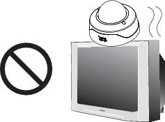
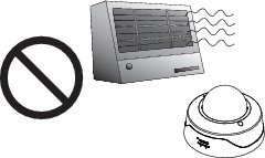
Warnings Before Installation


 |
Warning |
|
Warning |

Note ![]() If you use the IP camera outdoors, place the camera and the power supply in a suitable NEMA enclosure.
If you use the IP camera outdoors, place the camera and the power supply in a suitable NEMA enclosure.
|
Warning |

Note ![]() The power adapter that you use with the IP camera must provide power that is within +/-10% of the required power.
The power adapter that you use with the IP camera must provide power that is within +/-10% of the required power.
Note ![]() The equipment is to be connected to a Listed class 2, limited power source.
The equipment is to be connected to a Listed class 2, limited power source.
IP Camera Installation
Install the 3520 IP camera using one of the following procedures:
•![]() Mounting the IP Camera Directly to a Surface
Mounting the IP Camera Directly to a Surface
•![]() Mounting the IP Camera Flush with a Surface
Mounting the IP Camera Flush with a Surface
•![]() Mounting the IP camera with a Vandal Resistant Enclosure
Mounting the IP camera with a Vandal Resistant Enclosure
Mounting the IP Camera Directly to a Surface
To directly mount the 3520 IP camera to a surface, complete the following steps:
Procedure
Step 1 ![]() Attach the included alignment sticker to the ceiling or wall.
Attach the included alignment sticker to the ceiling or wall.
Step 2 ![]() Using the circle marks on the sticker, drill 2 pilot holes symmetrically on each side into the ceiling or wall. Then hammer the included wall anchors into the holes.
Using the circle marks on the sticker, drill 2 pilot holes symmetrically on each side into the ceiling or wall. Then hammer the included wall anchors into the holes.
Step 3 ![]() Secure the IP camera to the ceiling or wall with the included screws.
Secure the IP camera to the ceiling or wall with the included screws.
Step 4 ![]() Connect an STP (shielded twisted pair) Category 5 or higher network cable to the LAN port on the back of the camera. Connect the other end of the network cable to a 10/100/BaseT router or switch.
Connect an STP (shielded twisted pair) Category 5 or higher network cable to the LAN port on the back of the camera. Connect the other end of the network cable to a 10/100/BaseT router or switch.
If your network provides PoE, the IP camera powers on.
Step 5 ![]() (Optional) Connect the following cables to the GPIO terminal block:
(Optional) Connect the following cables to the GPIO terminal block:
•![]() External power cable if Power over Ethernet (PoE) is not available.
External power cable if Power over Ethernet (PoE) is not available.
•![]() I/O cables for external input or out put devices, such as sensors or alarms.
I/O cables for external input or out put devices, such as sensors or alarms.
The GPIO terminal block pin locations and descriptions are as follows:
|
|
|
1 |
12 VDC- |
|
2 |
12 VDC+ |
|
3 |
24 VAC |
|
4 |
24 VAC |
|
5 |
DI- |
|
6 |
DI+ |
|
7 |
DO- |
|
8 |
DO+ |

Step 6 ![]() (Optional) Use a mini cable with BNC connector to temporarily attach an NTSC or PAL compliant analog video display device to the analog video out port on the IP camera.
(Optional) Use a mini cable with BNC connector to temporarily attach an NTSC or PAL compliant analog video display device to the analog video out port on the IP camera.
Note ![]() The mini cable with BNC adapter is included in the audio/video cables accessory kit, which you can purchase from Cisco (Cisco part number CIVS-AVCABLE).
The mini cable with BNC adapter is included in the audio/video cables accessory kit, which you can purchase from Cisco (Cisco part number CIVS-AVCABLE).
Analog video is enabled by default to allow you to adjust the camera field of view during installation. However, it is not supported as a normal camera feed and is automatically disabled when any of the following camera settings are made:
•![]() The primary video stream frame rate must be set higher than 15 fps.
The primary video stream frame rate must be set higher than 15 fps.
•![]() The secondary video stream must is enabled.
The secondary video stream must is enabled.
Note ![]() We recommend that you disable analog video after installation. To disable analog video, see the Cisco Video Surveillance 3000 Series IP Camera Configuration Guide.
We recommend that you disable analog video after installation. To disable analog video, see the Cisco Video Surveillance 3000 Series IP Camera Configuration Guide.
Step 7 ![]() Remove the black cover.
Remove the black cover.
Step 8 ![]() While viewing video from the IP camera, perform the following steps to adjust the 3-axis field of view:
While viewing video from the IP camera, perform the following steps to adjust the 3-axis field of view:
a. ![]() Grip the two tilt adjustment screws and pan the IP camera left or right.
Grip the two tilt adjustment screws and pan the IP camera left or right.
b. ![]() Loosen the two thumb screws, tilt the IP camera, then tighten the thumb screws.
Loosen the two thumb screws, tilt the IP camera, then tighten the thumb screws.
c. ![]() Rotate the IP camera to adjust the image horizontal orientation.
Rotate the IP camera to adjust the image horizontal orientation.
Step 9 ![]() While viewing video from the IP camera, perform the following steps to adjust the focal length and zoom factor.
While viewing video from the IP camera, perform the following steps to adjust the focal length and zoom factor.
a. ![]() Loosen the locking screw on the focus ring, adjust the focal length (from near to infinity [·]) to achieve a sharp image, then tighten the locking screw.
Loosen the locking screw on the focus ring, adjust the focal length (from near to infinity [·]) to achieve a sharp image, then tighten the locking screw.
b. ![]() Loosen the locking screw on the zoom ring, adjust the zoom factor (from telephoto to wide angle) to achieve the desired field of view, then tighten the locking screw. If the focus is no longer sharp after adjusting the zoom, repeat Step 7a to achieve a sharp image.
Loosen the locking screw on the zoom ring, adjust the zoom factor (from telephoto to wide angle) to achieve the desired field of view, then tighten the locking screw. If the focus is no longer sharp after adjusting the zoom, repeat Step 7a to achieve a sharp image.
Step 10 ![]() Install the black cover.
Install the black cover.
Step 11 ![]() Attach the dome cover to the IP camera base by aligning it with the mounting holes.
Attach the dome cover to the IP camera base by aligning it with the mounting holes.
Step 12 ![]() Use the included screwdriver to tighten the four dome cover screws to secure the dome cover to the IP camera. Make sure all parts of the IP camera are securely installed.
Use the included screwdriver to tighten the four dome cover screws to secure the dome cover to the IP camera. Make sure all parts of the IP camera are securely installed.
What to do next
After you install the IP camera, follow the instructions in the "Performing the Initial Setup of the IP Camera" section to access the IP camera through your network.
Mounting the IP Camera Flush with a Surface
To mount the 3520 IP camera flush with a surface, complete the following steps:
Procedure
Step 1 ![]() Secure the IP camera inside the camera housing using the two included screws.
Secure the IP camera inside the camera housing using the two included screws.
Step 2 ![]() Remove the ceiling tile from the location at which you want to mount the IP dome and cut a 7-3/4 inch (19.68 cm) diameter hole in the center of the tile.
Remove the ceiling tile from the location at which you want to mount the IP dome and cut a 7-3/4 inch (19.68 cm) diameter hole in the center of the tile.
Step 3 ![]() Place the camera housing through the hole that you cut in the ceiling tile.
Place the camera housing through the hole that you cut in the ceiling tile.
Step 4 ![]() (Optional) Place a ceiling tile mount over the camera housing.
(Optional) Place a ceiling tile mount over the camera housing.
Orient the ceiling tile mount so that it is flush with the back surface of the ceiling tile.
Step 5 ![]() Use a Phillips-head screwdriver to turn the anchor screws clockwise and spin the anchor clips outward into the locking position and to secure the anchor clips.
Use a Phillips-head screwdriver to turn the anchor screws clockwise and spin the anchor clips outward into the locking position and to secure the anchor clips.
The anchor clips twist over the ceiling tile. Turn the anchor clip screws until the camera housing is snug against the ceiling tile. Do not over tighten the screws.
Step 6 ![]() Connect a shielded twisted pair (STP) Category 5 or higher network cable to the LAN port on the back of the camera through the cutout in the camera housing. Connect the other end of the network cable to a 10/100/BaseT router or switch.
Connect a shielded twisted pair (STP) Category 5 or higher network cable to the LAN port on the back of the camera through the cutout in the camera housing. Connect the other end of the network cable to a 10/100/BaseT router or switch.
If your network provides PoE, the IP camera powers on.
Step 7 ![]() (Optional) Connect the following cables to the GPIO terminal block on the IP camera through the cutout in the camera housing:
(Optional) Connect the following cables to the GPIO terminal block on the IP camera through the cutout in the camera housing:
•![]() External power cable to the GPIO terminal block if PoE is not available.
External power cable to the GPIO terminal block if PoE is not available.
•![]() (Optional) I/O cables for external input or out put devices, such as sensors or alarms, to the GPIO terminal block
(Optional) I/O cables for external input or out put devices, such as sensors or alarms, to the GPIO terminal block
The GPIO terminal block pin locations and descriptions are as follows:
|
|
|
|
1 |
12 VDC- |
|
2 |
12 VDC+ |
|
3 |
24 VAC |
|
4 |
24 VAC |
|
5 |
DI- |
|
6 |
DI+ |
|
7 |
DO- |
|
8 |
DO+ |
Step 8 ![]() Replace the ceiling tile with the camera installed.
Replace the ceiling tile with the camera installed.
Step 9 ![]() (Optional) Use a mini cable with BNC connector to temporarily attach an NTSC or PAL compliant analog video display device to the analog video out port on the IP camera.
(Optional) Use a mini cable with BNC connector to temporarily attach an NTSC or PAL compliant analog video display device to the analog video out port on the IP camera.
You may need to temporarily remove and adjacent ceiling tile to access the analog video out port.
Note ![]() The mini cable with BNC adapter is included in the audio/video cables accessory kit, which you can purchase from Cisco (Cisco part number CIVS-AVCABLE).
The mini cable with BNC adapter is included in the audio/video cables accessory kit, which you can purchase from Cisco (Cisco part number CIVS-AVCABLE).
Analog video is enabled by default to allow you to adjust the camera field of view during installation. However, it is not supported as a normal camera feed and is automatically disabled when any of the following camera settings are made:
•![]() The primary video stream frame rate must be set higher than 15 fps.
The primary video stream frame rate must be set higher than 15 fps.
•![]() The secondary video stream must is enabled.
The secondary video stream must is enabled.
Note ![]() We recommend that you disable analog video after installation. To disable analog video, see the Cisco Video Surveillance 3000 Series IP Camera Configuration Guide.
We recommend that you disable analog video after installation. To disable analog video, see the Cisco Video Surveillance 3000 Series IP Camera Configuration Guide.
Step 10 ![]() Remove the black cover.
Remove the black cover.
Step 11 ![]() While viewing video from the IP camera, perform the following steps to adjust the 3-axis field of view:
While viewing video from the IP camera, perform the following steps to adjust the 3-axis field of view:
a. ![]() Grip the two tilt adjustment screws and pan the IP camera left or right.
Grip the two tilt adjustment screws and pan the IP camera left or right.
b. ![]() Loosen the two thumb screws, tilt the IP camera, then tighten the thumb screws.
Loosen the two thumb screws, tilt the IP camera, then tighten the thumb screws.
c. ![]() Rotate the IP camera to adjust the image horizontal orientation.
Rotate the IP camera to adjust the image horizontal orientation.
Step 12 ![]() While viewing video from the IP camera, perform the following steps to adjust the focal length and zoom factor.
While viewing video from the IP camera, perform the following steps to adjust the focal length and zoom factor.
a. ![]() Loosen the locking screw on the focus ring, adjust the focal length (from near to infinity [·]) to achieve a sharp image, then tighten the locking screw.
Loosen the locking screw on the focus ring, adjust the focal length (from near to infinity [·]) to achieve a sharp image, then tighten the locking screw.
b. ![]() Loosen the locking screw on the zoom ring, adjust the zoom factor (from telephoto to wide angle) to achieve the desired field of view, then tighten the locking screw. If the focus is no longer sharp after adjusting the zoom, repeat Step 7a to achieve a sharp image.
Loosen the locking screw on the zoom ring, adjust the zoom factor (from telephoto to wide angle) to achieve the desired field of view, then tighten the locking screw. If the focus is no longer sharp after adjusting the zoom, repeat Step 7a to achieve a sharp image.
Step 13 ![]() Install the black cover. Make sure to adjust the it inside the dome and trim ring assembly so that it does not block the lens from capturing video.
Install the black cover. Make sure to adjust the it inside the dome and trim ring assembly so that it does not block the lens from capturing video.
Step 14 ![]() Attach the security strap from the dome and trim ring assembly to the camera housing using the included screw.
Attach the security strap from the dome and trim ring assembly to the camera housing using the included screw.
Step 15 ![]() Attach the dome and trim ring assembly by positioning its pegs in the slots of the camera housing and twisting clockwise.
Attach the dome and trim ring assembly by positioning its pegs in the slots of the camera housing and twisting clockwise.
What to do next
After you install the IP camera, follow the instructions in the "Performing the Initial Setup of the IP Camera" section to access the IP camera through your network.
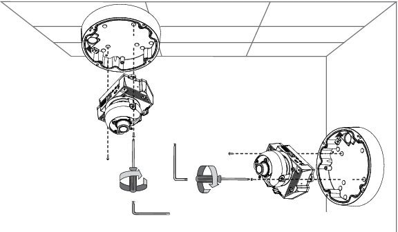
Mounting the IP camera with a Vandal Resistant Enclosure
To mount the 3520 IP camera using a vandal resistant (VR) enclosure, complete the following steps:
Procedure
Step 1 ![]() Attach the included alignment sticker to the ceiling or wall.
Attach the included alignment sticker to the ceiling or wall.
Step 2 ![]() Using the circle marks on the sticker, drill at least 2 pilot holes symmetrically on each side into the ceiling or wall. Then hammer the included plastic anchors into the holes.
Using the circle marks on the sticker, drill at least 2 pilot holes symmetrically on each side into the ceiling or wall. Then hammer the included plastic anchors into the holes.
Step 3 ![]() Do one of the following:
Do one of the following:
•![]() To feed cables through a ceiling or wall, cut out a section of the ceiling or wall that corresponds to the triangular cutout on the alignment sticker.
To feed cables through a ceiling or wall, cut out a section of the ceiling or wall that corresponds to the triangular cutout on the alignment sticker.
•![]() To feed cables through the side of the conduit base, use a screwdriver to remove the cutout on the side of the conduit base.
To feed cables through the side of the conduit base, use a screwdriver to remove the cutout on the side of the conduit base.
Step 4 ![]() Secure the conduit base to the ceiling or wall with two included screws.
Secure the conduit base to the ceiling or wall with two included screws.

Step 5 ![]() Secure the IP camera to the conduit base with two included screws.
Secure the IP camera to the conduit base with two included screws.
Step 6 ![]() Feed a shielded twisted pair (STP) Category 5 or higher network cable through the conduit base and connect to the LAN port on the back of the camera. Connect the other end of the network cable to a 10/100/BaseT router or switch.
Feed a shielded twisted pair (STP) Category 5 or higher network cable through the conduit base and connect to the LAN port on the back of the camera. Connect the other end of the network cable to a 10/100/BaseT router or switch.
If your network provides PoE, the IP camera powers on.
Step 7 ![]() (Optional) Feed the following cables through the conduit base and connect to the GPIO terminal block on the IP camera:
(Optional) Feed the following cables through the conduit base and connect to the GPIO terminal block on the IP camera:
•![]() External power cable to the GPIO terminal block if PoE is not available.
External power cable to the GPIO terminal block if PoE is not available.
•![]() (Optional) I/O cables for external input or out put devices, such as sensors or alarms, to the GPIO terminal block
(Optional) I/O cables for external input or out put devices, such as sensors or alarms, to the GPIO terminal block
The pin locations and descriptions are as follows:
|
|
|
|
1 |
12 VDC- |
|
2 |
12 VDC+ |
|
3 |
24 VAC |
|
4 |
24 VAC |
|
5 |
DI- |
|
6 |
DI+ |
|
7 |
DO- |
|
8 |
DO+ |
Step 8 ![]() (Optional) Use a mini cable with BNC connector to temporarily attach an NTSC or PAL compliant analog video display device to the analog video out port on the IP camera.
(Optional) Use a mini cable with BNC connector to temporarily attach an NTSC or PAL compliant analog video display device to the analog video out port on the IP camera.
Note ![]() The mini cable with BNC adapter is included in the audio/video cables accessory kit, which you can purchase from Cisco (Cisco part number CIVS-AVCABLE).
The mini cable with BNC adapter is included in the audio/video cables accessory kit, which you can purchase from Cisco (Cisco part number CIVS-AVCABLE).
Analog video is enabled by default to allow you to adjust the camera field of view during installation. However, it is not supported as a normal camera feed and is automatically disabled when any of the following camera settings are made:
•![]() The primary video stream frame rate must be set higher than 15 fps.
The primary video stream frame rate must be set higher than 15 fps.
•![]() The secondary video stream must is enabled.
The secondary video stream must is enabled.
Note ![]() We recommend that you disable analog video after installation. To disable analog video, see the Cisco Video Surveillance 3000 Series IP Camera Configuration Guide.
We recommend that you disable analog video after installation. To disable analog video, see the Cisco Video Surveillance 3000 Series IP Camera Configuration Guide.
Step 9 ![]() Remove the black cover.
Remove the black cover.
Step 10 ![]() While viewing video from the IP camera, perform the following steps to adjust the 3-axis field of view:
While viewing video from the IP camera, perform the following steps to adjust the 3-axis field of view:
a. ![]() Grip the two tilt adjustment screws and pan the IP camera left or right.
Grip the two tilt adjustment screws and pan the IP camera left or right.
b. ![]() Loosen the two thumb screws, tilt the IP camera, then tighten the thumb screws.
Loosen the two thumb screws, tilt the IP camera, then tighten the thumb screws.
c. ![]() Rotate the IP camera to adjust the image horizontal orientation.
Rotate the IP camera to adjust the image horizontal orientation.
Step 11 ![]() While viewing video from the IP camera, perform the following steps to adjust the focal length and zoom factor.
While viewing video from the IP camera, perform the following steps to adjust the focal length and zoom factor.
a. ![]() Loosen the locking screw on the focus ring, adjust the focal length (from near to infinity [·]) to achieve a sharp image, then tighten the locking screw.
Loosen the locking screw on the focus ring, adjust the focal length (from near to infinity [·]) to achieve a sharp image, then tighten the locking screw.
b. ![]() Loosen the locking screw on the zoom ring, adjust the zoom factor (from telephoto to wide angle) to achieve the desired field of view, then tighten the locking screw. If the focus is no longer sharp after adjusting the zoom, repeat Step 7a to achieve a sharp image.
Loosen the locking screw on the zoom ring, adjust the zoom factor (from telephoto to wide angle) to achieve the desired field of view, then tighten the locking screw. If the focus is no longer sharp after adjusting the zoom, repeat Step 7a to achieve a sharp image.
Step 12 ![]() After you have adjusted the field of view, focal length, and zoom factor, install the black cover. Make sure to adjust the it so that it does not block the lens from capturing video.
After you have adjusted the field of view, focal length, and zoom factor, install the black cover. Make sure to adjust the it so that it does not block the lens from capturing video.
Step 13 ![]() Attach the dome cover to the conduit base by aligning it with the mounting holes.
Attach the dome cover to the conduit base by aligning it with the mounting holes.
Step 14 ![]() Use the included wrench and tighten the four dome cover screws to secure the dome cover to the camera. Make sure all parts of the camera are securely installed.
Use the included wrench and tighten the four dome cover screws to secure the dome cover to the camera. Make sure all parts of the camera are securely installed.
What to do next
After you install the IP camera, follow the instructions in the "Performing the Initial Setup of the IP Camera" section to access the IP camera through your network.
 Feedback