-
null
Bias-Free Language
The documentation set for this product strives to use bias-free language. For the purposes of this documentation set, bias-free is defined as language that does not imply discrimination based on age, disability, gender, racial identity, ethnic identity, sexual orientation, socioeconomic status, and intersectionality. Exceptions may be present in the documentation due to language that is hardcoded in the user interfaces of the product software, language used based on RFP documentation, or language that is used by a referenced third-party product. Learn more about how Cisco is using Inclusive Language.
- Updated:
- June 22, 2009
Chapter: Managing Routers
- Configuring Routers Running IOS Software Releases 12.1 and 12.2
- Discovering Router Policies
- NAT on Cisco IOS Routers
- Basic Interface Settings on Cisco IOS Routers
- Advanced Interface Settings on Cisco IOS Routers
- IPS Module Interface Settings on Cisco IOS Routers
- CEF Interface Settings on Cisco IOS Routers
- Dialer Interfaces on Cisco IOS Routers
- ADSL on Cisco IOS Routers
- SHDSL on Cisco IOS Routers
- PVCs on Cisco IOS Routers
- PPP on Cisco IOS Routers
- AAA on Cisco IOS Routers
- User Accounts and Device Credentials on Cisco IOS Routers
- Bridging on Cisco IOS Routers
- Time Zone Settings on Cisco IOS Routers
- CPU Utilization Settings on Cisco IOS Routers
- HTTP and HTTPS on Cisco IOS Routers
- Line Access on Cisco IOS Routers
- Optional SSH Settings on Cisco IOS Routers
- SNMP on Cisco IOS Routers
- DNS on Cisco IOS Routers
- Hostnames and Domain Names on Cisco IOS Routers
- Memory Settings on Cisco IOS Routers
- Secure Device Provisioning on Cisco IOS Routers
- DHCP on Cisco IOS Routers
- NTP on Cisco IOS Routers
- 802.1x on Cisco IOS Routers
- Network Admission Control on Cisco IOS Routers
- Logging on Cisco IOS Routers
Managing Routers
Cisco Security Manager supports the management and configuration of security features and other platform-specific features on Cisco IOS access security routers. You configure these features in the form of policies, each of which defines a different aspect of the configuration of the router. For a detailed explanation of the policy paradigm used by Security Manager, see Chapter 6, "Managing Policies".
You can discover the configurations that are already defined on Cisco IOS routers. The discovery process imports the device configuration into Security Manager as policies and policy objects that you can then manage as required. For more information, see Discovering Router Policies.

Note ![]() Security Manager supports Cisco IOS Software Releases 12.3 and higher. However, a limited number of policies are supported for routers running Cisco IOS Software Release 12.1 or 12.2. See Configuring Routers Running IOS Software Releases 12.1 and 12.2.
Security Manager supports Cisco IOS Software Releases 12.3 and higher. However, a limited number of policies are supported for routers running Cisco IOS Software Release 12.1 or 12.2. See Configuring Routers Running IOS Software Releases 12.1 and 12.2.
By right-clicking a policy type in one of the policy selectors, you can assign a policy to a single router, share the policy among multiple routers, or unassign the policy from the device.
The following topics describe how to configure platform policies and interface policies on Cisco IOS routers:
•![]() Network address translation:
Network address translation:
•![]() Interface polices:
Interface polices:
–![]() Basic Interface Settings on Cisco IOS Routers
Basic Interface Settings on Cisco IOS Routers
–![]() Advanced Interface Settings on Cisco IOS Routers
Advanced Interface Settings on Cisco IOS Routers
–![]() IPS Module Interface Settings on Cisco IOS Routers
IPS Module Interface Settings on Cisco IOS Routers
–![]() CEF Interface Settings on Cisco IOS Routers
CEF Interface Settings on Cisco IOS Routers
–![]() Dialer Interfaces on Cisco IOS Routers
Dialer Interfaces on Cisco IOS Routers
•![]() Device administration policies:
Device administration policies:
–![]() User Accounts and Device Credentials on Cisco IOS Routers
User Accounts and Device Credentials on Cisco IOS Routers
–![]() Bridging on Cisco IOS Routers
Bridging on Cisco IOS Routers
–![]() Time Zone Settings on Cisco IOS Routers
Time Zone Settings on Cisco IOS Routers
–![]() CPU Utilization Settings on Cisco IOS Routers
CPU Utilization Settings on Cisco IOS Routers
–![]() HTTP and HTTPS on Cisco IOS Routers
HTTP and HTTPS on Cisco IOS Routers
–![]() Line Access on Cisco IOS Routers
Line Access on Cisco IOS Routers
–![]() Optional SSH Settings on Cisco IOS Routers
Optional SSH Settings on Cisco IOS Routers
–![]() Hostnames and Domain Names on Cisco IOS Routers
Hostnames and Domain Names on Cisco IOS Routers
–![]() Memory Settings on Cisco IOS Routers
Memory Settings on Cisco IOS Routers
–![]() Secure Device Provisioning on Cisco IOS Routers
Secure Device Provisioning on Cisco IOS Routers
•![]() Identity policies:
Identity policies:
–![]() Network Admission Control on Cisco IOS Routers
Network Admission Control on Cisco IOS Routers
•![]() Logging policies:
Logging policies:
•![]() Quality of Service:
Quality of Service:
–![]() Quality of Service on Cisco IOS Routers
Quality of Service on Cisco IOS Routers
•![]() Routing policies:
Routing policies:
–![]() BGP Routing on Cisco IOS Routers
BGP Routing on Cisco IOS Routers
–![]() EIGRP Routing on Cisco IOS Routers
EIGRP Routing on Cisco IOS Routers
–![]() OSPF Routing on Cisco IOS Routers
OSPF Routing on Cisco IOS Routers
–![]() RIP Routing on Cisco IOS Routers
RIP Routing on Cisco IOS Routers
–![]() Static Routing on Cisco IOS Routers
Static Routing on Cisco IOS Routers
Note ![]() The settings on the Policy Management page of the Security Manager Administration window determine which router platform policies can be managed with Security Manager. Any policy type that you do not select in this window does not appear on the configuration pages of Security Manager.
The settings on the Policy Management page of the Security Manager Administration window determine which router platform policies can be managed with Security Manager. Any policy type that you do not select in this window does not appear on the configuration pages of Security Manager.
Configuring Routers Running IOS Software Releases 12.1 and 12.2
Security Manager provides limited support for routers running Cisco IOS Software Releases 12.1 and 12.2 (with the exception of the ASR 1000 Series, which supports more features). You can configure the following policies on these routers:
•![]() Access Rules (Layer 3 only). See Working with Access Rules, page 11-17.
Access Rules (Layer 3 only). See Working with Access Rules, page 11-17.
•![]() Access Rule Settings. See Working with Access Rules, page 11-17.
Access Rule Settings. See Working with Access Rules, page 11-17.
•![]() Interfaces. See Basic Interface Settings on Cisco IOS Routers.
Interfaces. See Basic Interface Settings on Cisco IOS Routers.
•![]() FlexConfigs. See Chapter 18, "Managing FlexConfigs".
FlexConfigs. See Chapter 18, "Managing FlexConfigs".
All other policies require Cisco IOS Software Release 12.3 or higher. For more information about supported devices, see Supported Devices and Software Versions for Cisco Security Manager at:
http://www.cisco.com/en/US/products/ps6498/products_device_support_tables_list.html
Discovering Router Policies
You can discover the configurations of your Cisco IOS routers and import these configurations as policies into Security Manager. This makes it possible to add existing devices and manage them with Security Manager without having to manually configure each device policy by policy. For more information, see Adding Devices to the Device Inventory, page 5-7.
You can discover all Cisco IOS commands that can be configured with Security Manager. Discovery ignores unsupported commands, which means that they are left intact on the device even after subsequent deployments. Additionally, in cases where Security Manager can discover the command, but not all the subcommands and keywords related to that command, the unsupported elements are ignored and left intact on the device.
You can also rediscover the configurations of devices that you are already managing with Security Manager at any time. Be aware, however, that performing rediscovery overwrites the policies that you have defined in Security Manager, and is therefore not generally recommended. For more information, see Discovering Policies on Devices Already in Security Manager, page 6-14.
Note ![]() We recommend that you perform deployment immediately after you discover the policies on a Cisco IOS router, before you make any changes to policies or unassign policies from the device. Otherwise, the changes that you configure in Security Manager might not be deployed to the device.
We recommend that you perform deployment immediately after you discover the policies on a Cisco IOS router, before you make any changes to policies or unassign policies from the device. Otherwise, the changes that you configure in Security Manager might not be deployed to the device.
Note ![]() If a policy that is not configured in Security Manager was configured on the device using an out-of-band method (such as the CLI) between the time of the first discovery and rediscovery, we recommend that you perform deployment immediately after rediscovery.
If a policy that is not configured in Security Manager was configured on the device using an out-of-band method (such as the CLI) between the time of the first discovery and rediscovery, we recommend that you perform deployment immediately after rediscovery.
Related Topics
•![]() Understanding Policies, page 6-1
Understanding Policies, page 6-1
•![]() Discovering Policies, page 6-11
Discovering Policies, page 6-11
•![]() Working with Deployment and the Configuration Archive, page 17-15
Working with Deployment and the Configuration Archive, page 17-15
NAT on Cisco IOS Routers
Network Address Translation (NAT) is a form of address translation that extends addressing capabilities by providing both static address translations and dynamic address translations. NAT enables a host that does not have a valid registered IP address to communicate with other hosts through the Internet, as shown in Figure 13-1.
The hosts might be using private addresses or addresses assigned to another organization; in either case, NAT allows these addresses that are not Internet-ready to continue to be used while allowing communication with hosts across the Internet.
Figure 13-1 NAT Addressing Flow

Sites inside a VPN can use NAT through a split tunnel to exchange nonconfidential traffic with outside devices without wasting VPN bandwidth on nonessential traffic.
The following topics describe the tasks you perform to create NAT policies on Cisco IOS routers:
•![]() Designating Inside and Outside Interfaces
Designating Inside and Outside Interfaces
Designating Inside and Outside Interfaces
Before you create any NAT rules, you should designate the inside and outside interfaces on the router to use in NAT translations. Inside interfaces typically connect to a LAN that the router serves. Outside interfaces typically connect to your organization's WAN or to the Internet. You must designate at least one inside interface and one outside interface for the router to perform NAT.
NAT uses the Inside and Outside designations when interpreting translation rules, translating the original, inside addresses to outside ones. After these interfaces are designated, they are used in all static and dynamic NAT translation rules.
Related Topics
Step 1 ![]() Do one of the following:
Do one of the following:
•![]() (Device view) Select NAT from the Policy selector, then click the Interface Specification tab in the work area.
(Device view) Select NAT from the Policy selector, then click the Interface Specification tab in the work area.
•![]() (Policy view) Select NAT (Router) > Translation Rules from the Policy Type selector. Select an existing policy or create a new one, and then click the Interface Specification tab.
(Policy view) Select NAT (Router) > Translation Rules from the Policy Type selector. Select an existing policy or create a new one, and then click the Interface Specification tab.
The NAT Interface Specification tab is displayed (see NAT Page—Interface Specification Tab, page J-3).
Step 2 ![]() In the NAT Inside Interfaces and NAT Outside Interfaces fields, type in the names of the interfaces or interface roles for the inside and outside interfaces. Separate multiple names or roles with commands (for example, Ethernet1/1, Ethernet1/2). You cannot enter the same name in both fields.
In the NAT Inside Interfaces and NAT Outside Interfaces fields, type in the names of the interfaces or interface roles for the inside and outside interfaces. Separate multiple names or roles with commands (for example, Ethernet1/1, Ethernet1/2). You cannot enter the same name in both fields.
Click Select to select interface names or roles from a list of existing objects, or to create new interface role objects.
Defining Static NAT Rules
You define a static NAT rule by defining the inside local address that must be translated and the inside global address to which it is translated. You can define static NAT rules that translate the addresses of single hosts as well as static rules that translate multiple addresses in a subnet. When multiple inside local addresses must use the same inside global address, you must define the necessary port redirection information, which specifies a different port for each local address using the global address.
Note ![]() We strongly recommend that you not perform NAT on traffic that is meant to be transmitted over a VPN. Translating addresses on this traffic causes it to be sent out unencrypted instead of encrypted over the VPN.
We strongly recommend that you not perform NAT on traffic that is meant to be transmitted over a VPN. Translating addresses on this traffic causes it to be sent out unencrypted instead of encrypted over the VPN.
The procedure for creating a static rule depends on whether the address being translated represents a port, a single host, or an entire subnet, as described in the following sections:
•![]() Defining a Static NAT Rule for a Host
Defining a Static NAT Rule for a Host
•![]() Defining a Static NAT Rule for a Subnet
Defining a Static NAT Rule for a Subnet
•![]() Defining a Static NAT Rule for a Port
Defining a Static NAT Rule for a Port
Related Topics
Defining a Static NAT Rule for a Host
You define a static NAT rule for a single host by entering the original address to translate and the global address to which it should be translated. The global address may be taken from an interface on the device.
Before You Begin
•![]() Define the inside and outside interfaces used for NAT. See Designating Inside and Outside Interfaces.
Define the inside and outside interfaces used for NAT. See Designating Inside and Outside Interfaces.
Related Topics
•![]() Defining a Static NAT Rule for a Subnet
Defining a Static NAT Rule for a Subnet
•![]() Defining a Static NAT Rule for a Port
Defining a Static NAT Rule for a Port
Step 1 ![]() Do one of the following:
Do one of the following:
•![]() (Device view) Select NAT from the Policy selector, then click the Static Rules tab in the work area.
(Device view) Select NAT from the Policy selector, then click the Static Rules tab in the work area.
•![]() (Policy view) Select NAT (Router) > Translation Rules from the Policy Type selector. Select an existing policy or create a new one, and then click the Static Rules tab.
(Policy view) Select NAT (Router) > Translation Rules from the Policy Type selector. Select an existing policy or create a new one, and then click the Static Rules tab.
The NAT Static Rules tab is displayed. See Table J-1 on page J-4 for a description of the fields on this tab.
Step 2 ![]() On the NAT Static Rules tab, select a static NAT rule from the table, then click the Edit button, or click the Add button to create a rule.
On the NAT Static Rules tab, select a static NAT rule from the table, then click the Edit button, or click the Add button to create a rule.
The NAT Static Rule dialog box is displayed. See Table J-2 on page J-5 for a description of the fields in this dialog box.
Step 3 ![]() Select Static Host from the Static Rule Type list.
Select Static Host from the Static Rule Type list.
Step 4 ![]() Under Original Address, enter the host address to translate in the Original IP/Network field, or click Select to display a selector (see Object Selectors, page F-205). For more information, see Specifying IP Addresses During Policy Definition, page 8-68.
Under Original Address, enter the host address to translate in the Original IP/Network field, or click Select to display a selector (see Object Selectors, page F-205). For more information, see Specifying IP Addresses During Policy Definition, page 8-68.

Tip ![]() If the host you want is not listed in the selector, click the Create button or the Edit button to display the Add or Edit Network/Host Dialog Box, page F-141. From here you can create a network/host object to use in the policy.
If the host you want is not listed in the selector, click the Create button or the Edit button to display the Add or Edit Network/Host Dialog Box, page F-141. From here you can create a network/host object to use in the policy.
Note ![]() We recommend not entering a local address belonging to this router, as it could cause Security Manager management traffic to be translated. Translating this traffic causes a loss of communication between the router and Security Manager.
We recommend not entering a local address belonging to this router, as it could cause Security Manager management traffic to be translated. Translating this traffic causes a loss of communication between the router and Security Manager.
Step 5 ![]() Under Translated Address, select the type of address translation to perform:
Under Translated Address, select the type of address translation to perform:
•![]() To base translation on a specific address, select Specify IP, then enter the global address in the field provided, or click Select to display a selector (see Object Selectors, page F-205).
To base translation on a specific address, select Specify IP, then enter the global address in the field provided, or click Select to display a selector (see Object Selectors, page F-205).
•![]() To base translation on an interface with a globally registered IP address, select Use Interface IP, then enter the name of an interface or interface role, or click Select to display a selector. Only one static rule may be defined per interface.
To base translation on an interface with a globally registered IP address, select Use Interface IP, then enter the name of an interface or interface role, or click Select to display a selector. Only one static rule may be defined per interface.
Tip ![]() If the interface role you want is not listed, click the Create button or the Edit button in the selector to display the Interface Role Dialog Box, page F-56. From here you can define an interface role to use in the policy.
If the interface role you want is not listed, click the Create button or the Edit button in the selector to display the Interface Role Dialog Box, page F-56. From here you can define an interface role to use in the policy.
Step 6 ![]() (Optional when Translated IP is selected) Under Advanced, select one or more of the following options:
(Optional when Translated IP is selected) Under Advanced, select one or more of the following options:
•![]() Select the No alias check box to prevent an alias from being created for the global address. See Disabling the Alias Option for Attached Subnets.
Select the No alias check box to prevent an alias from being created for the global address. See Disabling the Alias Option for Attached Subnets.
•![]() Select the No payload check box to prevent an embedded address or port in the payload from being translated. Disabling the Payload Option for Overlapping Networks.
Select the No payload check box to prevent an embedded address or port in the payload from being translated. Disabling the Payload Option for Overlapping Networks.
•![]() Deselect the Create Extended Translation Entry check box to limit each local address to a single global address.
Deselect the Create Extended Translation Entry check box to limit each local address to a single global address.
Step 7 ![]() Click OK to save your definitions locally on the client and close the dialog box. The static NAT rule appears in the table in the NAT Static Rules tab.
Click OK to save your definitions locally on the client and close the dialog box. The static NAT rule appears in the table in the NAT Static Rules tab.
Defining a Static NAT Rule for a Subnet
You define a static NAT rule for a subnet by entering one of the addresses in the subnet (including the subnet mask) as the original address and one of the global addresses that you want to use as the translated address. The router configures the remaining addresses based on the subnet mask you provide.
Before You Begin
•![]() Define the inside and outside interfaces used for NAT. See Designating Inside and Outside Interfaces.
Define the inside and outside interfaces used for NAT. See Designating Inside and Outside Interfaces.
Related Topics
•![]() Defining a Static NAT Rule for a Host
Defining a Static NAT Rule for a Host
•![]() Defining a Static NAT Rule for a Port
Defining a Static NAT Rule for a Port
Step 1 ![]() Do one of the following:
Do one of the following:
•![]() (Device view) Select NAT from the Policy selector, then click the Static Rules tab in the work area.
(Device view) Select NAT from the Policy selector, then click the Static Rules tab in the work area.
•![]() (Policy view) Select NAT (Router) > Translation Rules from the Policy Type selector. Select an existing policy or create a new one, and then click the Static Rules tab.
(Policy view) Select NAT (Router) > Translation Rules from the Policy Type selector. Select an existing policy or create a new one, and then click the Static Rules tab.
The NAT Static Rules tab is displayed. See Table J-1 on page J-4 for a description of the fields on this tab.
Step 2 ![]() On the NAT Static Rules tab, select a static NAT rule from the table, then click the Edit button, or click the Add button to create a rule.
On the NAT Static Rules tab, select a static NAT rule from the table, then click the Edit button, or click the Add button to create a rule.
The NAT Static Rule dialog box is displayed. See Table J-2 on page J-5 for a description of the fields in this dialog box.
Step 3 ![]() Select Static Network from the Static Rule Type list.
Select Static Network from the Static Rule Type list.
Step 4 ![]() Under Original Address, enter the network address to be translated in the Original IP/Network field, or click Select to display a selector (see Object Selectors, page F-205). For more information, see Specifying IP Addresses During Policy Definition, page 8-68.
Under Original Address, enter the network address to be translated in the Original IP/Network field, or click Select to display a selector (see Object Selectors, page F-205). For more information, see Specifying IP Addresses During Policy Definition, page 8-68.
Tip ![]() If the network you want is not listed in the selector, click the Create button or the Edit button to display the Add or Edit Network/Host Dialog Box, page F-141. From here you can create a network/host object to use in the policy.
If the network you want is not listed in the selector, click the Create button or the Edit button to display the Add or Edit Network/Host Dialog Box, page F-141. From here you can create a network/host object to use in the policy.
Note ![]() We recommend not entering a local address belonging to this router, as it could cause Security Manager management traffic to be translated. Translating this traffic causes a loss of communication between the router and Security Manager.
We recommend not entering a local address belonging to this router, as it could cause Security Manager management traffic to be translated. Translating this traffic causes a loss of communication between the router and Security Manager.
Step 5 ![]() Under Translated Address, select Specify IP, then enter the IP address that you want to use in the translation in the Translated IP/Network field, or click Select to display a selector (see Object Selectors, page F-205).
Under Translated Address, select Specify IP, then enter the IP address that you want to use in the translation in the Translated IP/Network field, or click Select to display a selector (see Object Selectors, page F-205).
Step 6 ![]() (Optional) Under Advanced, select one or more of the following options:
(Optional) Under Advanced, select one or more of the following options:
•![]() Select the No alias check box to prevent an alias from being created for the global address. See Disabling the Alias Option for Attached Subnets.
Select the No alias check box to prevent an alias from being created for the global address. See Disabling the Alias Option for Attached Subnets.
•![]() Select the No payload check box to prevent an embedded address or port in the payload from being translated. Disabling the Payload Option for Overlapping Networks.
Select the No payload check box to prevent an embedded address or port in the payload from being translated. Disabling the Payload Option for Overlapping Networks.
•![]() Deselect the Create Extended Translation Entry check box to limit each local address to a single global address.
Deselect the Create Extended Translation Entry check box to limit each local address to a single global address.
Step 7 ![]() Click OK to save your definitions locally on the client and close the dialog box. The static NAT rule appears in the table in the NAT Static Rules tab.
Click OK to save your definitions locally on the client and close the dialog box. The static NAT rule appears in the table in the NAT Static Rules tab.
Defining a Static NAT Rule for a Port
You define a static NAT rule for a port by entering the original IP address and the global address to which it should be translated. The global address may be taken from an interface on the device. In addition, you must select the protocol used by the port as well as the local and global port numbers.
Before You Begin
•![]() Define the inside and outside interfaces used for NAT. See Designating Inside and Outside Interfaces.
Define the inside and outside interfaces used for NAT. See Designating Inside and Outside Interfaces.
Related Topics
•![]() Defining a Static NAT Rule for a Host
Defining a Static NAT Rule for a Host
•![]() Defining a Static NAT Rule for a Subnet
Defining a Static NAT Rule for a Subnet
Step 1 ![]() Do one of the following:
Do one of the following:
•![]() (Device view) Select NAT from the Policy selector, then click the Static Rules tab in the work area.
(Device view) Select NAT from the Policy selector, then click the Static Rules tab in the work area.
•![]() (Policy view) Select NAT (Router) > Translation Rules from the Policy Type selector. Select an existing policy or create a new one, and then click the Static Rules tab.
(Policy view) Select NAT (Router) > Translation Rules from the Policy Type selector. Select an existing policy or create a new one, and then click the Static Rules tab.
The NAT Static Rules tab is displayed. See Table J-1 on page J-4 for a description of the fields on this tab.
Step 2 ![]() On the NAT Static Rules tab, select a static NAT rule from the table, then click Edit, or click Add to create a rule. The NAT Static Rule dialog box is displayed. See Table J-2 on page J-5 for a description of the fields in this dialog box.
On the NAT Static Rules tab, select a static NAT rule from the table, then click Edit, or click Add to create a rule. The NAT Static Rule dialog box is displayed. See Table J-2 on page J-5 for a description of the fields in this dialog box.
Step 3 ![]() Select Static Port from the Static Rule Type list.
Select Static Port from the Static Rule Type list.
Step 4 ![]() Under Original Address, enter the address to translate in the Original IP/Network field, or click Select to display a selector (see Object Selectors, page F-205). For more information, see Specifying IP Addresses During Policy Definition, page 8-68.
Under Original Address, enter the address to translate in the Original IP/Network field, or click Select to display a selector (see Object Selectors, page F-205). For more information, see Specifying IP Addresses During Policy Definition, page 8-68.
If the object you want is not listed in the selector, click the Create button or the Edit button to display the Add or Edit Network/Host Dialog Box, page F-141. From here you can create a network/host object to use in the policy.
Note ![]() We recommend not entering a local address belonging to this router, as it could cause Security Manager management traffic to be translated. Translating this traffic will cause a loss of communication between the router and Security Manager.
We recommend not entering a local address belonging to this router, as it could cause Security Manager management traffic to be translated. Translating this traffic will cause a loss of communication between the router and Security Manager.
Step 5 ![]() Under Translated Address, select the type of address translation to perform:
Under Translated Address, select the type of address translation to perform:
•![]() To base translation on a specific address, select Specify IP, then enter the global address in the Translated IP/Network field, or click Select to display a selector (see Object Selectors, page F-205).
To base translation on a specific address, select Specify IP, then enter the global address in the Translated IP/Network field, or click Select to display a selector (see Object Selectors, page F-205).
•![]() To base translation on an interface with a globally registered IP address, select Interface, then enter the name of an interface or interface role, or click Select to display a selector (see Object Selectors, page F-205).
To base translation on an interface with a globally registered IP address, select Interface, then enter the name of an interface or interface role, or click Select to display a selector (see Object Selectors, page F-205).
Tip ![]() If the interface role you want is not listed, click the Create button or the Edit button in the selector to display the Interface Role Dialog Box, page F-56. From here you can define an interface role to use in the policy.
If the interface role you want is not listed, click the Create button or the Edit button in the selector to display the Interface Role Dialog Box, page F-56. From here you can define an interface role to use in the policy.
Step 6 ![]() Under Port Redirection, include port information for the inside device in the translation:
Under Port Redirection, include port information for the inside device in the translation:
a. ![]() Select a protocol (TCP or UDP).
Select a protocol (TCP or UDP).
b. ![]() Enter the port number on the inside device and the port number to use for the translation. This enables you to use the same public IP address for multiple devices as long as the port specified for each device is different.
Enter the port number on the inside device and the port number to use for the translation. This enables you to use the same public IP address for multiple devices as long as the port specified for each device is different.
Step 7 ![]() (Optional when Translated IP selected) Under Advanced, select one or more of the following options:
(Optional when Translated IP selected) Under Advanced, select one or more of the following options:
•![]() Select the No alias check box to prevent an alias from being created for the global address. See Disabling the Alias Option for Attached Subnets.
Select the No alias check box to prevent an alias from being created for the global address. See Disabling the Alias Option for Attached Subnets.
•![]() Select the No payload check box to prevent an embedded address or port in the payload from being translated. Disabling the Payload Option for Overlapping Networks.
Select the No payload check box to prevent an embedded address or port in the payload from being translated. Disabling the Payload Option for Overlapping Networks.
•![]() Deselect the Create Extended Translation Entry check box to limit each local address to a single global address.
Deselect the Create Extended Translation Entry check box to limit each local address to a single global address.
Step 8 ![]() Click OK to save your definitions locally on the client and close the dialog box. The static NAT rule appears in the table in the NAT Static Rules tab.
Click OK to save your definitions locally on the client and close the dialog box. The static NAT rule appears in the table in the NAT Static Rules tab.
Disabling the Alias Option for Attached Subnets
If the NAT pool used as an inside global pool consists of addresses on an attached subnet, an alias is generated for that address so that the router can answer Address Resolution Protocol (ARP) requests for those addresses.
To disable automatic aliasing, select the No alias check box when you create a static NAT rule based on a global IP translation.
Related Topics
•![]() Disabling the Payload Option for Overlapping Networks
Disabling the Payload Option for Overlapping Networks
Disabling the Payload Option for Overlapping Networks
Overlapping networks result when you assign an IP address to a device on your network that is already legally owned and assigned to a different device on the Internet or outside network. Overlapping networks can also result after the merger of two companies using RFC 1918 IP addresses in their networks. These two networks need to communicate, preferably without your having to re-address all their devices.
This communication is achieved as follows. The outside device cannot use the IP address of the inside device because it is the same as the address assigned to itself (the outside device). Instead, the outside device sends a Domain Name System (DNS) query for the inside device's domain name. The source of this query is the IP address of the outside device, which is translated to an address from a designated address pool. The DNS server located on the inside network replies with the IP address associated with the inside device's domain name in the data portion of the packet. The destination address of the reply packet is translated back to the outside device's address, and the address in the data portion of the reply packet is translated to an address from a different address pool. In this way, the outside device learns that the IP address for the inside device is one of the addresses from that second address pool, and it uses this address when it communicates with the inside device. The router running NAT takes care of the translations at this point.
To disable the translation of the address inside the payload, select the No payload check box when you create a static NAT rule based on a global IP translation.
Related Topics
•![]() Disabling the Alias Option for Attached Subnets
Disabling the Alias Option for Attached Subnets
Defining Dynamic NAT Rules
You define a dynamic NAT rule by selecting the access list (ACL) whose rules specify the traffic requiring translation.
In addition, you must either select an interface with an IP address to which the addresses should be translated or define an address pool. You define the pool by specifying a range of addresses and giving the range a unique name. The configured router uses the available addresses in the pool (those not used for static translations or for its own WAN IP address) for connections to the Internet or other outside network. When an address is no longer in use, it is returned to the address pool to be dynamically assigned later to another device. Access lists (ACLs) define the traffic requiring translation.
If the addressing requirements of your network exceed the available addresses in your dynamic NAT pool, you can use the Port Address Translation (PAT) feature (also called Overload) to associate many private NAT addresses with a small group of public IP address through port addressing. With PAT enabled, the router chooses a unique port number for the PAT IP address of each outbound translation slot. This feature is useful if you cannot allocate enough unique IP addresses for your outbound connections. The global pool addresses always come before a PAT address is used.
Note ![]() By default, Security Manager does not perform NAT on traffic that is meant to be transmitted over a VPN. Otherwise, any traffic appearing in both the NAT ACL and the crypto ACL defined on an interface would be sent out unencrypted because NAT is always performed before encryption. However, you can change this default setting.
By default, Security Manager does not perform NAT on traffic that is meant to be transmitted over a VPN. Otherwise, any traffic appearing in both the NAT ACL and the crypto ACL defined on an interface would be sent out unencrypted because NAT is always performed before encryption. However, you can change this default setting.
Tip ![]() You can perform PAT on split-tunneled traffic on the spokes of your VPN topology directly from the Global VPN Settings page. There is no need to create a dynamic NAT rule for each spoke using the NAT policy, as described in this procedure. Any NAT rules that you define on an individual device override the VPN setting. For more information, see NAT Settings Tab, page G-68.
You can perform PAT on split-tunneled traffic on the spokes of your VPN topology directly from the Global VPN Settings page. There is no need to create a dynamic NAT rule for each spoke using the NAT policy, as described in this procedure. Any NAT rules that you define on an individual device override the VPN setting. For more information, see NAT Settings Tab, page G-68.
Related Topics
•![]() Designating Inside and Outside Interfaces
Designating Inside and Outside Interfaces
Step 1 ![]() Do one of the following:
Do one of the following:
•![]() (Device view) Select NAT from the Policy selector, then click the Dynamic Rules tab in the work area.
(Device view) Select NAT from the Policy selector, then click the Dynamic Rules tab in the work area.
•![]() (Policy view) Select NAT (Router) > Translation Rules from the Policy Type selector. Select an existing policy or create a new one, and then click the Dynamic Rules tab.
(Policy view) Select NAT (Router) > Translation Rules from the Policy Type selector. Select an existing policy or create a new one, and then click the Dynamic Rules tab.
The NAT Dynamic Rules tab is displayed. See Table J-3 on page J-8 for a description of the fields on this tab.
Step 2 ![]() On the NAT Dynamic Rules tab, select a dynamic NAT rule from the table, then click Edit, or click Add to create a rule. The NAT Dynamic Rule dialog box appears. See Table J-4 on page J-9 for a description of the fields in this dialog box.
On the NAT Dynamic Rules tab, select a dynamic NAT rule from the table, then click Edit, or click Add to create a rule. The NAT Dynamic Rule dialog box appears. See Table J-4 on page J-9 for a description of the fields in this dialog box.
Step 3 ![]() Under Traffic Flow, enter the name of the ACL object whose rules specify the addresses requiring translation in the Access List field, or click Select to display a selector (see Object Selectors, page F-205).
Under Traffic Flow, enter the name of the ACL object whose rules specify the addresses requiring translation in the Access List field, or click Select to display a selector (see Object Selectors, page F-205).
Tip ![]() If the required ACL is not listed in the selector, click the Create button to create it.
If the required ACL is not listed in the selector, click the Create button to create it.
Note ![]() Make sure that the ACL you select does not permit the translation of Security Manager management traffic over any device address on this router. Translating this traffic will cause a loss of communication between the router and Security Manager.
Make sure that the ACL you select does not permit the translation of Security Manager management traffic over any device address on this router. Translating this traffic will cause a loss of communication between the router and Security Manager.
Step 4 ![]() Under Translated Address, select an address translation option:
Under Translated Address, select an address translation option:
•![]() To base address translation on an interface with a globally registered IP address, select Interface, then enter an interface or interface role, or click Select to display a selector (see Object Selectors, page F-205). The interface or interface role must represent an outside interface on the router for you to configure the dynamic NAT rule (see Designating Inside and Outside Interfaces).
To base address translation on an interface with a globally registered IP address, select Interface, then enter an interface or interface role, or click Select to display a selector (see Object Selectors, page F-205). The interface or interface role must represent an outside interface on the router for you to configure the dynamic NAT rule (see Designating Inside and Outside Interfaces).
Tip ![]() If the interface role you want is not listed, click the Create button or the Edit button in the selector to display the Interface Role Dialog Box. From here you can define an interface role to use in the policy.
If the interface role you want is not listed, click the Create button or the Edit button in the selector to display the Interface Role Dialog Box. From here you can define an interface role to use in the policy.
•![]() To base address translation on the addresses found in a predefined pool, select Address Pool, then enter one or more address ranges, including the prefix, using the format min1-max1/prefix (in CIDR notation). You can add as many address ranges to the address pool as required, but all ranges must share the same prefix. Separate multiple entries with commas.
To base address translation on the addresses found in a predefined pool, select Address Pool, then enter one or more address ranges, including the prefix, using the format min1-max1/prefix (in CIDR notation). You can add as many address ranges to the address pool as required, but all ranges must share the same prefix. Separate multiple entries with commas.
Step 5 ![]() (Optional) Select the Enable Port Translation (Overload) check box to enable the use of PAT if the supply of global addresses in the address pool runs out.
(Optional) Select the Enable Port Translation (Overload) check box to enable the use of PAT if the supply of global addresses in the address pool runs out.
This option is selected by default when you select Interface as the source of the translated address.
Step 6 ![]() (Optional) Deselect the Do Not Translate VPN Traffic check box to perform address translation on traffic meant for a site-to-site VPN.
(Optional) Deselect the Do Not Translate VPN Traffic check box to perform address translation on traffic meant for a site-to-site VPN.
Note ![]() We strongly recommend that you not deselect this check box, because it causes any traffic appearing in both the NAT ACL and the crypto ACL to be sent unencrypted. When you perform NAT into IPsec, we also recommend that you leave this check box selected; it does not interfere with the translation of addresses arriving from overlapping networks.
We strongly recommend that you not deselect this check box, because it causes any traffic appearing in both the NAT ACL and the crypto ACL to be sent unencrypted. When you perform NAT into IPsec, we also recommend that you leave this check box selected; it does not interfere with the translation of addresses arriving from overlapping networks.
Step 7 ![]() Click OK to save your definitions locally on the client and close the dialog box. The dynamic NAT rule appears in the table on the NAT Dynamic Rules tab.
Click OK to save your definitions locally on the client and close the dialog box. The dynamic NAT rule appears in the table on the NAT Dynamic Rules tab.
Specifying NAT Timeouts
Dynamic NAT translations have a timeout period for non-use, after which they expire and are purged from the translation table. If you enable the Overload feature for performing PAT, you can specify a variety of values that provide finer control over these timeouts, because each translation entry contains additional context about the traffic using it. For more information about Overload, see Defining Dynamic NAT Rules.
For example, non-DNS translations time out by default after 5 minutes, but DNS translations time out after 1 minute. TCP translations time out after 24 hours, unless an RST or FIN is seen on the stream, in which case they time out after 1 minute. You can change any of the default timeout values.
If you disable the Overload feature, you need not enter any timeout values. However, you can modify the default timeout value for dynamic translations that are not PAT translations. (By default, all dynamic translations expire after 24 hours.)
Related Topics
•![]() Designating Inside and Outside Interfaces
Designating Inside and Outside Interfaces
Step 1 ![]() Do one of the following:
Do one of the following:
•![]() (Device view) Select NAT from the Policy selector, then click the Timeouts tab in the work area.
(Device view) Select NAT from the Policy selector, then click the Timeouts tab in the work area.
•![]() (Policy view) Select NAT (Router) > Translation Rules from the Policy Type selector. Select an existing policy or create a new one, and then click the Timeouts tab.
(Policy view) Select NAT (Router) > Translation Rules from the Policy Type selector. Select an existing policy or create a new one, and then click the Timeouts tab.
The NAT Timeouts tab is displayed. See Table J-5 on page J-10 for a description of the fields on this tab.
Step 2 ![]() (Optional) Enter the maximum number of entries allowed in the dynamic NAT rules table in the Max Entries field. If you leave this field blank, there is no limit to the number of table entries allowed.
(Optional) Enter the maximum number of entries allowed in the dynamic NAT rules table in the Max Entries field. If you leave this field blank, there is no limit to the number of table entries allowed.
Step 3 ![]() (Optional) Modify the number of seconds after which dynamic translations expire in the Timeout field.
(Optional) Modify the number of seconds after which dynamic translations expire in the Timeout field.
Step 4 ![]() (Optional) If you enabled PAT for dynamic translations, modify the default timeout values as required. See Table J-5 on page J-10 for a description of the available timeouts.
(Optional) If you enabled PAT for dynamic translations, modify the default timeout values as required. See Table J-5 on page J-10 for a description of the available timeouts.
Basic Interface Settings on Cisco IOS Routers
You typically add interfaces to Security Manager by performing discovery, as described in Discovering Policies, page 6-11. After you have discovered the interfaces, you can modify the properties of each interface.
You can also use Security Manager to configure physical and virtual interfaces manually. This is useful when you modify interface configurations of existing devices, and makes it possible for you to configure all the interfaces of a device before you physically add the device to the network.
Related Topics
•![]() Defining Basic Router Interface Settings
Defining Basic Router Interface Settings
•![]() Deleting a Cisco IOS Router Interface
Deleting a Cisco IOS Router Interface
Available Interface Types
Table 13-1 describes the types of interfaces that can be configured on Cisco IOS routers.
|
|
|
|---|---|
Null |
Null interface. |
Analysis-module |
A Fast Ethernet interface that connects to the internal interface on the Network Analysis Module (NAM). Note |
Async |
Port line used as an asynchronous interface. |
ATM |
ATM interface. |
BRI |
ISDN BRI interface. This interface configuration propagates to each B channel. B channels cannot be configured individually. Note |
BVI |
Bridge-group virtual interface. BVI interfaces are used to route traffic at Layer 3 to the interfaces in a bridge group. |
Content-engine |
Content engine (CE) network module interface. Note |
Dialer |
Dialer interface. |
Ethernet |
Ethernet IEEE 802.3 interface. |
Fast Ethernet |
100-Mbps Ethernet interface. |
FDDI |
Fiber Distributed Data Interface. |
Gigabit Ethernet |
1000-Mbps Ethernet interface. |
Group-Async |
Master asynchronous interface. This interface type creates a single asynchronous interfaces to which other interfaces are associated. This one-to-many configuration enables you to configure all associated member interfaces by configuring the master interface. |
HSSI |
High-Speed Serial Interface. |
Loopback |
A logical interface that emulates an interface that is always up. For example, having a loopback interface on the router prevents a loss of adjacency with neighboring OSPF routers if the physical interfaces on the router go down. The name of a loopback interface must end with a number ranging from 0-2147483647. Note |
Multilink |
Multilink interface. A logical interface used for multilink PPP (MLP). |
Port channel |
Port channel interface. This interface type enables you to bundle multiple point-to-point Fast Ethernet links into one logical link. It provides bidirectional bandwidth of up to 800 Mbps. |
POS |
Packet OC-3 interface on the Packet-over-SONET (POS) interface processor. |
PRI |
ISDN PRI interface. Includes 23/30 B-channels and one D-channel. |
Serial |
Serial interface. |
Switch |
Switch interface. |
Token Ring |
Token Ring interface. |
Tunnel |
Tunnel interface. Note |
VG-AnyLAN |
100VG-AnyLAN port adapter. |
VLAN |
Virtual LAN subinterface. |
Virtual Template |
Virtual template interface. When a user dials in, a predefined configuration template is used to configure a virtual access interface; when the user is done, the virtual access interface goes down and the resources are freed for other dial-in uses. |
Related Topics
•![]() Defining Basic Router Interface Settings
Defining Basic Router Interface Settings
•![]() Deleting a Cisco IOS Router Interface
Deleting a Cisco IOS Router Interface
•![]() Basic Interface Settings on Cisco IOS Routers
Basic Interface Settings on Cisco IOS Routers
Defining Basic Router Interface Settings
When you define an interface or subinterface for a Cisco IOS router, you name it, specify how it is assigned an IP address, and optionally define other properties, such as the speed, maximum transmission unit (MTU), and the encapsulation type.
Note ![]() Basic interface settings are always local to the device on which they are configured. You cannot share this policy with other devices. You can, however, share advanced interface settings. For more information, see Advanced Interface Settings on Cisco IOS Routers.
Basic interface settings are always local to the device on which they are configured. You cannot share this policy with other devices. You can, however, share advanced interface settings. For more information, see Advanced Interface Settings on Cisco IOS Routers.
Related Topics
•![]() Deleting a Cisco IOS Router Interface
Deleting a Cisco IOS Router Interface
Step 1 ![]() In Device view, select Interfaces > Interfaces from the Policy selector.
In Device view, select Interfaces > Interfaces from the Policy selector.
The Router Interfaces Page, page J-11 is displayed.
Step 2 ![]() To add a new interface or subinterface, click the Add Row button to open the Create Router Interface dialog box.
To add a new interface or subinterface, click the Add Row button to open the Create Router Interface dialog box.
To edit an existing interface or subinterface, select it in the Interfaces table, and then click the Edit Row button to open the Edit Router Interface dialog box. Refer to Create Router Interface Dialog Box, page J-12 for descriptions of the fields in these dialog boxes.
Step 3 ![]() Select Enabled to have Security Manager actively manage this interface or subinterface. If this option is deselected, the interface/subinterface definition is retained, but the interface/subinterface itself is disabled (or "shutdown").
Select Enabled to have Security Manager actively manage this interface or subinterface. If this option is deselected, the interface/subinterface definition is retained, but the interface/subinterface itself is disabled (or "shutdown").
Step 4 ![]() Choose Interface or Subinterface from the Type list.
Choose Interface or Subinterface from the Type list.
Step 5 ![]() If you are creating an interface, enter a name for the interface. You can click Select to open a dialog box that will help you generate a standard name based on interface type and details about the interface's location, such as card, slot, and subinterface. For more information on using the dialog box to generate an interface name, see Interface Auto Name Generator Dialog Box, page J-17.
If you are creating an interface, enter a name for the interface. You can click Select to open a dialog box that will help you generate a standard name based on interface type and details about the interface's location, such as card, slot, and subinterface. For more information on using the dialog box to generate an interface name, see Interface Auto Name Generator Dialog Box, page J-17.
Note ![]() When naming a BVI interface, use the bridge group number as the card number. Deployment will fail if you configure a BVI interface without configuring a corresponding bridge group.
When naming a BVI interface, use the bridge group number as the card number. Deployment will fail if you configure a BVI interface without configuring a corresponding bridge group.
Step 6 ![]() If you are creating a subinterface, provide the following:
If you are creating a subinterface, provide the following:
a. ![]() Parent—Choose the parent interface for this subinterface.
Parent—Choose the parent interface for this subinterface.
b. ![]() Subinterface ID—Enter a number to identify the subinterface.
Subinterface ID—Enter a number to identify the subinterface.
Note ![]() Security Manager configures serial subinterfaces as point-to-point, not multipoint.
Security Manager configures serial subinterfaces as point-to-point, not multipoint.
Step 7 ![]() To specify a Layer Type, choose a Level 2 (data link) or Level 3 (network) option from this list.
To specify a Layer Type, choose a Level 2 (data link) or Level 3 (network) option from this list.
Step 8 ![]() Choose a method of IP address assignment for this interface/subinterface, then provide additional information, as required:
Choose a method of IP address assignment for this interface/subinterface, then provide additional information, as required:
•![]() Static IP—Provide an IP Address and Subnet Mask.
Static IP—Provide an IP Address and Subnet Mask.
•![]() DHCP—No additional information is required.
DHCP—No additional information is required.
•![]() PPPoE—No additional information is required.
PPPoE—No additional information is required.
•![]() Unnumbered—Provide the name of the interface from which an IP address is to be "borrowed."
Unnumbered—Provide the name of the interface from which an IP address is to be "borrowed."
Note ![]() Layer 2 interfaces do not support IP addresses.
Layer 2 interfaces do not support IP addresses.
Step 9 ![]() Define additional properties of the interface/subinterface:
Define additional properties of the interface/subinterface:
•![]() Use the Negotiation check box to enable and disable auto-negotiation for the interface.
Use the Negotiation check box to enable and disable auto-negotiation for the interface.
Auto-negotiation detects the capabilities of remote devices and negotiates the best possible performance between the two devices. When Negotiation is enabled, the Fast Ethernet Duplex and Speed options are disabled.
Note ![]() Auto-negotiation is available only for Fast Ethernet and Gigabit Ethernet interfaces on ASR devices.
Auto-negotiation is available only for Fast Ethernet and Gigabit Ethernet interfaces on ASR devices.
•![]() Choose a transmission mode from the Duplex list. If you choose Auto, be sure the network device to which this interface is connected is set to automatically detect the transmission mode. (Auto is not available on ASRs; use auto-negotiation instead.)
Choose a transmission mode from the Duplex list. If you choose Auto, be sure the network device to which this interface is connected is set to automatically detect the transmission mode. (Auto is not available on ASRs; use auto-negotiation instead.)
Note ![]() You must configure a fixed speed to define the duplex value. Tunnel and loopback interfaces do not support this setting.
You must configure a fixed speed to define the duplex value. Tunnel and loopback interfaces do not support this setting.
•![]() Choose a transmission speed from the Speed list. If you choose Auto, be sure the network device to which this interface is connected is set to automatically detect the transmission speed. (Auto is not available on ASRs; use auto-negotiation instead.)
Choose a transmission speed from the Speed list. If you choose Auto, be sure the network device to which this interface is connected is set to automatically detect the transmission speed. (Auto is not available on ASRs; use auto-negotiation instead.)
•![]() Enter the maximum transmission unit (MTU), which defines the largest packet size, in bytes, that this interface can support.
Enter the maximum transmission unit (MTU), which defines the largest packet size, in bytes, that this interface can support.
Note ![]() Certain interface properties are set automatically, or are unavailable, depending on the interface type and the underlying port type. For example, the Speed options are available for Fast Ethernet and Gigabit Ethernet interfaces only.
Certain interface properties are set automatically, or are unavailable, depending on the interface type and the underlying port type. For example, the Speed options are available for Fast Ethernet and Gigabit Ethernet interfaces only.
Step 10 ![]() Choose an encapsulation method from the Encapsulation list:
Choose an encapsulation method from the Encapsulation list:
•![]() None—No encapsulation; no additional parameters are required.
None—No encapsulation; no additional parameters are required.
•![]() (Ethernet subinterfaces only) DOT1Q—VLAN encapsulation, as defined by the IEEE 802.1Q standard. Provide the following VLAN parameters for this subinterface:
(Ethernet subinterfaces only) DOT1Q—VLAN encapsulation, as defined by the IEEE 802.1Q standard. Provide the following VLAN parameters for this subinterface:
–![]() Enter a VLAN ID to associate with this subinterface.
Enter a VLAN ID to associate with this subinterface.
Note ![]() All VLAN IDs must be unique among all subinterfaces configured on the same physical interface.
All VLAN IDs must be unique among all subinterfaces configured on the same physical interface.
–![]() If you are defining the 802.1Q trunk interface, select Native VLAN.
If you are defining the 802.1Q trunk interface, select Native VLAN.
Tip ![]() To configure DOT1Q encapsulation on an Ethernet interface without associating a VLAN with the subinterface, enter the vlan-id dot1qcommand using CLI commands or FlexConfigs. See Understanding FlexConfig Policies and Policy Objects, page 18-1. Configuring VLANs on the main interface increases the number of VLANs that can be configured on the router.
To configure DOT1Q encapsulation on an Ethernet interface without associating a VLAN with the subinterface, enter the vlan-id dot1qcommand using CLI commands or FlexConfigs. See Understanding FlexConfig Policies and Policy Objects, page 18-1. Configuring VLANs on the main interface increases the number of VLANs that can be configured on the router.
•![]() (Serial interfaces only) Frame Relay—IETF Frame Relay encapsulation. Provide a data-link connection identifier (DLCI) for the subinterface.
(Serial interfaces only) Frame Relay—IETF Frame Relay encapsulation. Provide a data-link connection identifier (DLCI) for the subinterface.
Note ![]() Frame relay must be configured on the parent interface.
Frame relay must be configured on the parent interface.
Note ![]() IETF Frame Relay encapsulation provides interoperability between a Cisco IOS router and equipment from other vendors. To configure Cisco Frame Relay encapsulation, use CLI commands or FlexConfigs.
IETF Frame Relay encapsulation provides interoperability between a Cisco IOS router and equipment from other vendors. To configure Cisco Frame Relay encapsulation, use CLI commands or FlexConfigs.
Step 11 ![]() (Optional) Enter a description of up to 1024 characters for the interface.
(Optional) Enter a description of up to 1024 characters for the interface.
Step 12 ![]() Click OK to save the interface/subinterface definition and close the dialog box. The new interface is displayed on the Router Interfaces page. Subinterfaces are displayed beneath the parent interface.
Click OK to save the interface/subinterface definition and close the dialog box. The new interface is displayed on the Router Interfaces page. Subinterfaces are displayed beneath the parent interface.
Deleting a Cisco IOS Router Interface
Although you can delete the definition of a virtual interface at any time, use this option with great care. If the interface is included in any policy definitions that exist for this router, deleting the interface causes these policy definitions to fail when they are deployed to the device.
Note ![]() Deleting the basic interface definition does not delete any advanced settings that are configured under Interface > Settings > Advanced Settings. You must delete these advanced settings separately. If you fail to do so, deployment fails.
Deleting the basic interface definition does not delete any advanced settings that are configured under Interface > Settings > Advanced Settings. You must delete these advanced settings separately. If you fail to do so, deployment fails.
Note ![]() Deleting the definition of a physical interface from the Router Interfaces page does not remove the interface from the device. If you perform this operation by mistake, you can perform rediscovery to restore the definition to Security Manager. For more information, see Discovering Policies on Devices Already in Security Manager, page 6-14.
Deleting the definition of a physical interface from the Router Interfaces page does not remove the interface from the device. If you perform this operation by mistake, you can perform rediscovery to restore the definition to Security Manager. For more information, see Discovering Policies on Devices Already in Security Manager, page 6-14.
Related Topics
•![]() Defining Basic Router Interface Settings
Defining Basic Router Interface Settings
•![]() Basic Interface Settings on Cisco IOS Routers
Basic Interface Settings on Cisco IOS Routers
Step 1 ![]() Click the Device View button on the toolbar.
Click the Device View button on the toolbar.
Step 2 ![]() Select a router from the Device selector.
Select a router from the Device selector.
Step 3 ![]() Select Interfaces > Interfaces from the Policy selector. The Router Interfaces page is displayed. See Table J-6 on page J-11 for an explanation of the fields on this page.
Select Interfaces > Interfaces from the Policy selector. The Router Interfaces page is displayed. See Table J-6 on page J-11 for an explanation of the fields on this page.
Step 4 ![]() Select an interface from the table, then click the Delete button. The interface is deleted.
Select an interface from the table, then click the Delete button. The interface is deleted.
Advanced Interface Settings on Cisco IOS Routers
In addition to the basic interface definitions that you can define on the Interfaces page, Security Manager provides a method for defining selected advanced settings on interfaces that support those settings.
Unlike the basic interface settings defined on the Interface page, you can share an advanced settings policy with multiple devices. This provides a convenient method for configuring multiple devices with identical settings. See Working with Shared Policies in Device View, page 6-25.
You can define a variety of advanced settings on a selected interface, subinterface, or interface role, including:
•![]() Cisco Discovery Protocol (CDP) settings.
Cisco Discovery Protocol (CDP) settings.
•![]() Internet Control Message Protocol (ICMP) settings.
Internet Control Message Protocol (ICMP) settings.
•![]() Directed broadcast settings.
Directed broadcast settings.
•![]() Load interval for determining the average load.
Load interval for determining the average load.
•![]() Throughput delay for use by routing protocols.
Throughput delay for use by routing protocols.
•![]() Configuring TCP maximum segment size.
Configuring TCP maximum segment size.
•![]() Helper addresses for forwarding UDP broadcasts. For more information on helper addresses, see Understanding Helper Addresses.
Helper addresses for forwarding UDP broadcasts. For more information on helper addresses, see Understanding Helper Addresses.
•![]() Enabling Maintenance Operation Protocol (MOP).
Enabling Maintenance Operation Protocol (MOP).
•![]() Enabling virtual fragmentation reassembly (VFR).
Enabling virtual fragmentation reassembly (VFR).
•![]() Enabling proxy ARP.
Enabling proxy ARP.
•![]() Enabling NBAR protocol discovery.
Enabling NBAR protocol discovery.
•![]() Enabling and configuring unicast reverse path forwarding (RFP).
Enabling and configuring unicast reverse path forwarding (RFP).
Tip ![]() You can define these settings for multiple interfaces on a device at once by choosing an interface role instead of a specific interface. For example, if you have defined an All-Ethernets interface role, you can define identical advanced settings for every Ethernet interface on the device with a single definition. See Understanding Interface Role Objects, page 8-33.
You can define these settings for multiple interfaces on a device at once by choosing an interface role instead of a specific interface. For example, if you have defined an All-Ethernets interface role, you can define identical advanced settings for every Ethernet interface on the device with a single definition. See Understanding Interface Role Objects, page 8-33.
Before You Begin
•![]() Define basic interface settings. See Basic Interface Settings on Cisco IOS Routers.
Define basic interface settings. See Basic Interface Settings on Cisco IOS Routers.
Step 1 ![]() Do one of the following:
Do one of the following:
•![]() (Device view) Select Interfaces > Settings > Advanced Settings from the Policy selector.
(Device view) Select Interfaces > Settings > Advanced Settings from the Policy selector.
•![]() (Policy view) Select Router Interfaces > Settings > Advanced Settings from the Policy Type selector. Select an existing policy or create a new one.
(Policy view) Select Router Interfaces > Settings > Advanced Settings from the Policy Type selector. Select an existing policy or create a new one.
The Advanced Interface Settings page is displayed (see Advanced Interface Settings Page, page J-17).
Step 2 ![]() Do one of the following:
Do one of the following:
•![]() Click the Add button to add an interface or interface role to the table. In the Advanced Interface Settings dialog box, enter the name of the interface or interface role, or click Select to select an existing role or to create a new role.
Click the Add button to add an interface or interface role to the table. In the Advanced Interface Settings dialog box, enter the name of the interface or interface role, or click Select to select an existing role or to create a new role.
•![]() Select an existing entry in the table and click the Edit button to change its settings.
Select an existing entry in the table and click the Edit button to change its settings.
Step 3 ![]() Configure the advanced settings required for the selected interface. For details about each setting, see Advanced Interface Settings Dialog Box, page J-18.
Configure the advanced settings required for the selected interface. For details about each setting, see Advanced Interface Settings Dialog Box, page J-18.
Step 4 ![]() Click OK to save your definitions. Your definitions are displayed in the Advanced Interface Settings table.
Click OK to save your definitions. Your definitions are displayed in the Advanced Interface Settings table.
Understanding Helper Addresses
Network hosts occasionally use User Datagram Protocol (UDP) broadcasts to determine address, configuration, and name information. This presents a problem if the host is on a network segment that does not include the required server, as by default, routers do not forward UDP broadcasts beyond their subnet. You can remedy this situation by configuring the interface to forward certain classes of broadcasts to a helper address.
One common use of helper addresses is when the router acts as a relay agent for DHCP clients who need to contact a DHCP server located on a different subnet. The helper address can either represent a specific DHCP server or a network address for a segment containing multiple DHCP servers. You can also configure a helper address for each DHCP server.
In Figure 13-2, hosts located on network 192.168.1.0 can use 10.44.23.7 as a helper address to forward UDP broadcasts to the other network, while hosts located on network 10.44.0.0 can use 192.168.1.19 as their helper address.
Figure 13-2 Helper Addresses

Table 13-2 lists the default UDP services that can be forwarded to helper addresses.
Tip ![]() To forward additional UDP services, use the CLI or FlexConfigs to configure the ip forward-protocol command. Use the no form of this command to prevent the forwarding of any of the default services listed in Table 13-2.
To forward additional UDP services, use the CLI or FlexConfigs to configure the ip forward-protocol command. Use the no form of this command to prevent the forwarding of any of the default services listed in Table 13-2.
All of the following conditions must be met in order for a UDP or IP packet to use helper addresses:
•![]() The MAC address of the received frame must be an all-ones broadcast address (ffff.ffff.ffff).
The MAC address of the received frame must be an all-ones broadcast address (ffff.ffff.ffff).
•![]() The IP destination address must be one of the following: all-ones broadcast (255.255.255.255), subnet broadcast for the receiving interface, or major-net broadcast for the receiving interface if the no ip classless command is also configured.
The IP destination address must be one of the following: all-ones broadcast (255.255.255.255), subnet broadcast for the receiving interface, or major-net broadcast for the receiving interface if the no ip classless command is also configured.
•![]() The IP time-to-live (TTL) value must be at least 2.
The IP time-to-live (TTL) value must be at least 2.
•![]() The IP protocol must be UDP (17).
The IP protocol must be UDP (17).
Related Topics
•![]() Advanced Interface Settings on Cisco IOS Routers
Advanced Interface Settings on Cisco IOS Routers
•![]() Basic Interface Settings on Cisco IOS Routers
Basic Interface Settings on Cisco IOS Routers
IPS Module Interface Settings on Cisco IOS Routers
On some routers, you can install IPS modules such as the Cisco Intrusion Prevention System Advanced Integration Module or Network Module. When installed and active, you must configure the IPS Module interface settings policy to define the following:
•![]() The name of the interface between the module and the router.
The name of the interface between the module and the router.
•![]() The failure mode of the module. If the module fails, you can configure it to allow all traffic or to deny all traffic.
The failure mode of the module. If the module fails, you can configure it to allow all traffic or to deny all traffic.
•![]() The router interfaces to monitor. You can name specific interfaces or use interface roles to cover more than one interface at a time. For example, if you have defined an All-Ethernets interface role, you can define identical monitoring settings for every Ethernet interface on the device with a single definition. See Understanding Interface Role Objects, page 8-33.
The router interfaces to monitor. You can name specific interfaces or use interface roles to cover more than one interface at a time. For example, if you have defined an All-Ethernets interface role, you can define identical monitoring settings for every Ethernet interface on the device with a single definition. See Understanding Interface Role Objects, page 8-33.
Tip ![]() After you have defined an IPS Module interface settings policy, you can share the policy and assign it to other devices. This provides a convenient method for configuring multiple devices with identical settings. See Working with Shared Policies in Device View, page 6-25.
After you have defined an IPS Module interface settings policy, you can share the policy and assign it to other devices. This provides a convenient method for configuring multiple devices with identical settings. See Working with Shared Policies in Device View, page 6-25.
Before You Begin
Define basic interface settings. See Basic Interface Settings on Cisco IOS Routers.
Step 1 ![]() Do one of the following:
Do one of the following:
•![]() (Device view) Select Interfaces > Settings > IPS Module from the Policy selector.
(Device view) Select Interfaces > Settings > IPS Module from the Policy selector.
•![]() (Policy view) Select Router Interfaces > Settings > IPS Module from the Policy Type selector. Select an existing policy or create a new one.
(Policy view) Select Router Interfaces > Settings > IPS Module from the Policy Type selector. Select an existing policy or create a new one.
The IPS Module Interface Settings page is displayed. See IPS Module Interface Settings Page, page J-24 for an explanation of the fields on this page.
Step 2 ![]() In the IPS Module Interface Settings fields, enter the name of the IPS interface (such as IDS-Sensor1/0) or click Select to select it from a list. Also determine whether you want to allow all traffic if the module fails (fail open) or to deny all traffic (fail closed).
In the IPS Module Interface Settings fields, enter the name of the IPS interface (such as IDS-Sensor1/0) or click Select to select it from a list. Also determine whether you want to allow all traffic if the module fails (fail open) or to deny all traffic (fail closed).
Step 3 ![]() Identify the router interfaces that the module should monitor. Click the Add button below the IPS Module Service Module Monitoring Settings table to add interfaces to the list, or select an interface and click the Edit button to change the settings for an existing interface. Use the IPS Monitoring Information dialog box to define the interface name or role, monitoring mode, and access list (if any). For more information, see IPS Monitoring Information Dialog Box, page J-25.
Identify the router interfaces that the module should monitor. Click the Add button below the IPS Module Service Module Monitoring Settings table to add interfaces to the list, or select an interface and click the Edit button to change the settings for an existing interface. Use the IPS Monitoring Information dialog box to define the interface name or role, monitoring mode, and access list (if any). For more information, see IPS Monitoring Information Dialog Box, page J-25.
CEF Interface Settings on Cisco IOS Routers
Cisco Express Forwarding (CEF) is an advanced Layer 3 IP switching technology that optimizes network performance and scalability for all kinds of networks, from those that carry small amounts of traffic to those that carry large amounts of traffic in complex patterns, such as the Internet and networks characterized by intensive web-based applications or interactive sessions. CEF is enabled by default on most Cisco IOS routers.
Typically, you do not need to configure a CEF policy unless you want to enable CEF accounting so that you can view statistics with the show ip cef command on the router. You would also configure the policy if you want to disable CEF, or to configure non-default CEF behavior on specific interfaces, for example, to have CEF load balance based on packets rather than source-destination packet streams.
When configuring alternate CEF settings for interfaces, you can name specific interfaces or use interface roles to cover more than one interface at a time. For example, if you have defined an All-Ethernets interface role, you can define identical CEF settings for every Ethernet interface on the device with a single definition. See Understanding Interface Role Objects, page 8-33.
Tip ![]() After you have defined a CEF interface settings policy, you can share the policy and assign it to other devices. This provides a convenient method for configuring multiple devices with identical settings. See Working with Shared Policies in Device View, page 6-25.
After you have defined a CEF interface settings policy, you can share the policy and assign it to other devices. This provides a convenient method for configuring multiple devices with identical settings. See Working with Shared Policies in Device View, page 6-25.
Before You Begin
Define basic interface settings. See Basic Interface Settings on Cisco IOS Routers.
Step 1 ![]() Do one of the following:
Do one of the following:
•![]() (Device view) Select Interfaces > Settings > CEF from the Policy selector.
(Device view) Select Interfaces > Settings > CEF from the Policy selector.
•![]() (Policy view) Select Router Interfaces > Settings > CEF from the Policy Type selector. Select an existing policy or create a new one.
(Policy view) Select Router Interfaces > Settings > CEF from the Policy Type selector. Select an existing policy or create a new one.
The CEF Interface Settings page is displayed. See CEF Interface Settings Page, page J-26 for an explanation of the fields on this page.
Step 2 ![]() If you are enabling CEF, select the accounting options you desire.
If you are enabling CEF, select the accounting options you desire.
Step 3 ![]() If you want to configure non-default behavior for certain interfaces, add them to the CEF Interface Settings table. Click the Add button below the table to add interfaces to the list, or select an interface and click the Edit button to change the settings for an existing interface. For more information about the options, see CEF Interface Settings Dialog Box, page J-27.
If you want to configure non-default behavior for certain interfaces, add them to the CEF Interface Settings table. Click the Add button below the table to add interfaces to the list, or select an interface and click the Edit button to change the settings for an existing interface. For more information about the options, see CEF Interface Settings Dialog Box, page J-27.
Dialer Interfaces on Cisco IOS Routers
Before you can configure a dial backup policy for a site-to-site VPN (see Configuring Dial Backup, page 9-29), you must configure a dialer interface policy on the appropriate Cisco IOS router. The dialer interface policy uses dialer pools to associate the dialer interface used by dial backup with a physical BRI interface on the router. Each dialer interface is associated with a single dialer pool, which can contain one or more physical interfaces. Multiple dialer interfaces can reference the same dialer pool.
The following topics describe how to create dialer interfaces policies on Cisco IOS routers:
•![]() Defining BRI Interface Properties
Defining BRI Interface Properties
Defining Dialer Profiles
When you configure a dialer profile, you must select the interface or interface role representing the dialer interface and specify the number to be dialed. You must also assign a pool ID, which you use to reference this dialer interface when configuring the physical dialer interface. Additionally, you can modify the default timeout settings for the line.
Note ![]() IP is the only protocol supported for dialer profiles by Security Manager.
IP is the only protocol supported for dialer profiles by Security Manager.
Note ![]() Authentication parameters for the dialer profile are defined in the PPP policy.
Authentication parameters for the dialer profile are defined in the PPP policy.
Before You Begin
Define the virtual and physical dialer interfaces on the router. See Basic Interface Settings on Cisco IOS Routers.
Note ![]() In addition, you can optionally define interface roles for the virtual and physical dialer interfaces. See Defining Dialer Profiles.
In addition, you can optionally define interface roles for the virtual and physical dialer interfaces. See Defining Dialer Profiles.
Related Topics
•![]() Defining BRI Interface Properties
Defining BRI Interface Properties
•![]() Dialer Interfaces on Cisco IOS Routers
Dialer Interfaces on Cisco IOS Routers
Step 1 ![]() Do one of the following:
Do one of the following:
•![]() (Device view) Select Interfaces > Settings > Dialer from the Policy selector.
(Device view) Select Interfaces > Settings > Dialer from the Policy selector.
•![]() (Policy view) Select Router Interfaces > Settings > Dialer from the Policy Type selector. Select an existing policy or create a new one.
(Policy view) Select Router Interfaces > Settings > Dialer from the Policy Type selector. Select an existing policy or create a new one.
The Dialer page is displayed. See Table J-14 on page J-28 for a description of the fields on this page.
Step 2 ![]() Select a dialer profile from the upper table on the Dialer Interfaces page, then click Edit, or click Add to create a profile. The Dialer Profile dialog box appears. See Table J-15 on page J-30 for a description of the fields in this dialog box.
Select a dialer profile from the upper table on the Dialer Interfaces page, then click Edit, or click Add to create a profile. The Dialer Profile dialog box appears. See Table J-15 on page J-30 for a description of the fields in this dialog box.
Step 3 ![]() Enter the name of the interface or interface role that represents the virtual dialer interface, or click Select to display a selector (see Object Selectors, page F-205). For more information, see Specifying Interfaces During Policy Definition, page 8-35.
Enter the name of the interface or interface role that represents the virtual dialer interface, or click Select to display a selector (see Object Selectors, page F-205). For more information, see Specifying Interfaces During Policy Definition, page 8-35.
Tip ![]() If the interface role you want is not listed, click the Create button or the Edit button in the selector to open the Interface Role Dialog Box, page F-56. From here you can define an interface role to use in the policy.
If the interface role you want is not listed, click the Create button or the Edit button in the selector to open the Interface Role Dialog Box, page F-56. From here you can define an interface role to use in the policy.
Step 4 ![]() Enter a name for the dialer profile. Having a name makes it easier for you to assign the correct dialer pool to the physical interface. See Defining BRI Interface Properties.
Enter a name for the dialer profile. Having a name makes it easier for you to assign the correct dialer pool to the physical interface. See Defining BRI Interface Properties.
Tip ![]() We recommend that you define a name that is logically associated with the site to which the dialer interface serves as a backup. For example, if the dialer interface is serving as a backup connection to the London site, define the name London for the dialer profile.
We recommend that you define a name that is logically associated with the site to which the dialer interface serves as a backup. For example, if the dialer interface is serving as a backup connection to the London site, define the name London for the dialer profile.
Step 5 ![]() Enter an ID number for the dialer pool to associate with this dialer interface. Each dialer interface is associated with a single pool. Multiple interfaces may, however, be associated with the same dialer pool.
Enter an ID number for the dialer pool to associate with this dialer interface. Each dialer interface is associated with a single pool. Multiple interfaces may, however, be associated with the same dialer pool.
Step 6 ![]() Enter the number of the dialer group to assign to the dialer interface.
Enter the number of the dialer group to assign to the dialer interface.
Step 7 ![]() (Optional) In the Interesting Traffic ACL field, enter the name of the extended ACL object that defines which packets are permitted to initiate calls using this dialer profile, or click Select to display a selector (see Object Selectors, page F-205). Use this option to limit the IP traffic that can make use of the dialer.
(Optional) In the Interesting Traffic ACL field, enter the name of the extended ACL object that defines which packets are permitted to initiate calls using this dialer profile, or click Select to display a selector (see Object Selectors, page F-205). Use this option to limit the IP traffic that can make use of the dialer.
Note ![]() If the required ACL is not listed in the selector, click the Create button to create it.
If the required ACL is not listed in the selector, click the Create button to create it.
Step 8 ![]() Enter the dialer string, which is the phone number of the remote side of the dialer interface connection.
Enter the dialer string, which is the phone number of the remote side of the dialer interface connection.
Step 9 ![]() (Optional) Modify the default timeout values (Idle Timeout and Fast Idle Timeout), if required.
(Optional) Modify the default timeout values (Idle Timeout and Fast Idle Timeout), if required.
Step 10 ![]() Click OK to save your definitions locally on the client and close the dialog box. The dialer profile appears in the Dialer Profile table on the Dialer page.
Click OK to save your definitions locally on the client and close the dialog box. The dialer profile appears in the Dialer Profile table on the Dialer page.
Defining BRI Interface Properties
You configure the properties of the physical BRI interfaces used for dialer interface policies by selecting the appropriate interface or interface role, defining the dialer pools to which the interface belongs, and defining the ISDN switch type. It is the dialer pool that connects the physical interface with the virtual dialer interface.
Note ![]() To define other types of physical dialer interfaces, such as ATM and Ethernet, use FlexConfigs. For more information, see Understanding FlexConfig Policies and Policy Objects, page 18-1.
To define other types of physical dialer interfaces, such as ATM and Ethernet, use FlexConfigs. For more information, see Understanding FlexConfig Policies and Policy Objects, page 18-1.
Before You Begin
Define the virtual and physical dialer interfaces on the router. SeeBasic Interface Settings on Cisco IOS Routers.
Note ![]() In addition, you can optionally define interface roles for the virtual and physical dialer interfaces. See Creating Interface Role Objects, page 8-34.
In addition, you can optionally define interface roles for the virtual and physical dialer interfaces. See Creating Interface Role Objects, page 8-34.
Related Topics
•![]() Dialer Interfaces on Cisco IOS Routers
Dialer Interfaces on Cisco IOS Routers
Step 1 ![]() Do one of the following:
Do one of the following:
•![]() (Device view) Select Interfaces > Settings > Dialer from the Policy selector.
(Device view) Select Interfaces > Settings > Dialer from the Policy selector.
•![]() (Policy view) Select Router Interfaces > Settings > Dialer from the Policy Type selector. Select an existing policy or create a new one.
(Policy view) Select Router Interfaces > Settings > Dialer from the Policy Type selector. Select an existing policy or create a new one.
The Dialer Interfaces page is displayed. See Table J-14 on page J-28 for a description of the fields on this page.
Step 2 ![]() Select a physical BRI interface from the Dialer Physical Interfaces table, then click Edit, or click Add to add an interface. The Dialer Physical Interface dialog box appears. See Table J-16 on page J-31 for a description of the fields in this dialog box.
Select a physical BRI interface from the Dialer Physical Interfaces table, then click Edit, or click Add to add an interface. The Dialer Physical Interface dialog box appears. See Table J-16 on page J-31 for a description of the fields in this dialog box.
Step 3 ![]() Enter the name of the interface or interface role that represents the physical dialer interface, or click Select to display a selector (see Object Selectors, page F-205). For more information, see Specifying Interfaces During Policy Definition, page 8-35.
Enter the name of the interface or interface role that represents the physical dialer interface, or click Select to display a selector (see Object Selectors, page F-205). For more information, see Specifying Interfaces During Policy Definition, page 8-35.
Tip ![]() If the interface role you want is not listed, click the Create button or the Edit button in the selector to open the Interface Role Dialog Box, page F-56. From here you can define an interface role to use in the policy.
If the interface role you want is not listed, click the Create button or the Edit button in the selector to open the Interface Role Dialog Box, page F-56. From here you can define an interface role to use in the policy.
Step 4 ![]() Enter the names of the dialer pools to associate with the physical interface, or click Select to display a selector. Separate multiple entries with commas.
Enter the names of the dialer pools to associate with the physical interface, or click Select to display a selector. Separate multiple entries with commas.
Step 5 ![]() Select the ISDN switch type used by the physical interface. Table J-16 on page J-31 describes the available switch types.
Select the ISDN switch type used by the physical interface. Table J-16 on page J-31 describes the available switch types.
Step 6 ![]() (Optional) If you selected the Basic-DMS-100, Basic-NI, or Basic-5ess switch type, enter up to two service provider identifiers (SPIDs).
(Optional) If you selected the Basic-DMS-100, Basic-NI, or Basic-5ess switch type, enter up to two service provider identifiers (SPIDs).
Note ![]() We recommend that you do not enter SPIDs for the Basic-5ess switch type, even though SPIDs are supported.
We recommend that you do not enter SPIDs for the Basic-5ess switch type, even though SPIDs are supported.
Step 7 ![]() Click OK to save your definitions locally on the client and close the dialog box. The interface definition appears in the Dialer Physical Interfaces table on the Dialer Interface page.
Click OK to save your definitions locally on the client and close the dialog box. The interface definition appears in the Dialer Physical Interfaces table on the Dialer Interface page.
ADSL on Cisco IOS Routers
Digital Subscriber Line (DSL) is a family of technologies that transports data over existing twisted-pair copper wire. DSL uses frequencies that are beyond the upper list used by POTS (plain old telephone service) to deliver broadband applications, such as multimedia and video, over the local loop (or last mile) that connects the telephone company's central office to customer sites.
Asymmetric Digital Subscriber Line (ADSL) is a form of DSL where the data flow downstream to customer sites is much greater than the data flow upstream to the central office (CO). This asymmetric setup is well-suited for applications where users typically download far more information than they send, such as web surfing, video-on-demand, and remote LAN access. With ADSL, the connection speed is related to the distance between the customer site and the digital subscriber line-access multiplexer (DSLAM) that aggregates the connections from multiple customer sites onto a high-speed line.
ADSL downstream rates range from 1.5 to 9 Mbps, whereas upstream bandwidth ranges from 16 to 640 kbps. ADSL transmissions work at distances up to 18,000 feet (5,488 meters) over a single copper twisted pair. Newer versions of ADSL technology, such as ADSL2 and ADSL2+, offer even higher data rates for short distances, as well as power management and realtime performance monitoring.
ATM is used in many ADSL implementations due to its small, fixed-length cell size, which makes it suitable for carrying time-critical traffic, such as voice and video, in conjunction with other traffic. You can use Security Manager to configure ATM over DSL on a Cisco IOS router. For more information about configuring ADSL policies in Security Manager, see Defining ADSL Settings.
To configure ADSL in Security Manager, you must do the following:
1. ![]() Configure an ATM interface or subinterface. See Defining Basic Router Interface Settings.
Configure an ATM interface or subinterface. See Defining Basic Router Interface Settings.
2. ![]() Configure ADSL settings on the ATM interface or subinterface. See Defining ADSL Settings.
Configure ADSL settings on the ATM interface or subinterface. See Defining ADSL Settings.
3. ![]() Configure PVCs on the ATM interface or subinterface. See Defining ATM PVCs.
Configure PVCs on the ATM interface or subinterface. See Defining ATM PVCs.
Note ![]() If you perform discovery on the device, Security Manager populates the Interfaces policy with the ATM interface and subinterface and the ADSL policy with the ADSL settings for that interface. Any discovered PVCs are added to the PVC policy.
If you perform discovery on the device, Security Manager populates the Interfaces policy with the ATM interface and subinterface and the ADSL policy with the ADSL settings for that interface. Any discovered PVCs are added to the PVC policy.
Related Topics
•![]() Supported ADSL Operating Modes
Supported ADSL Operating Modes
Supported ADSL Operating Modes
Table 13-3 describes the operating modes that are supported on each ADSL interface card that can be configured with Security Manager.
Table 13-4 describes the operating modes that are supported on each ADSL device that can be configured with Security Manager.
Related Topics
Defining ADSL Settings
When you configure an ADSL definition in Security Manager, you must select the ATM interface on which ADSL is being defined. In addition, we highly recommend that you specify the router type or the type of WIC (WAN interface card) installed in the router. The validity of DSL policy definitions is highly dependent on the hardware. By specifying the hardware used by this policy, you enable Security Manager to properly validate the values you define and avoid deployment failures.
You can optionally specify the following parameters:
•![]() The DSL operating mode.
The DSL operating mode.
•![]() Whether to enable dynamic VC bandwidth adjustments when using Inverse Multiplexing over ATM (IMA).
Whether to enable dynamic VC bandwidth adjustments when using Inverse Multiplexing over ATM (IMA).
•![]() Whether certain interface cards should use a particular set of carrier tones.
Whether certain interface cards should use a particular set of carrier tones.
Modular Cisco IOS routers may contain multiple interface cards, each of which contains a single ATM interface. You may define only one ADSL definition per interface.
Before You Begin
•![]() Make sure that the device contains an ADSL ATM interface. See Basic Interface Settings on Cisco IOS Routers.
Make sure that the device contains an ADSL ATM interface. See Basic Interface Settings on Cisco IOS Routers.
Related Topics
•![]() Supported ADSL Operating Modes
Supported ADSL Operating Modes
Step 1 ![]() Do one of the following:
Do one of the following:
•![]() (Device view) Select Interfaces > Settings > DSL > ADSL from the Policy selector.
(Device view) Select Interfaces > Settings > DSL > ADSL from the Policy selector.
•![]() (Policy view) Select Router Interfaces > Settings > DSL > ADSL from the Policy Type selector. Select an existing policy or create a new one.
(Policy view) Select Router Interfaces > Settings > DSL > ADSL from the Policy Type selector. Select an existing policy or create a new one.
The ADSL page is displayed. See Table J-17 on page J-33 for a description of the fields on this page.
Step 2 ![]() Click the Add button beneath the table to display the ADSL Settings dialog box. See Table J-18 on page J-34 for a description of the fields in this dialog box.
Click the Add button beneath the table to display the ADSL Settings dialog box. See Table J-18 on page J-34 for a description of the fields in this dialog box.
Step 3 ![]() In the ATM Interface field, enter the name of the ATM interface or interface role on which you want to define ADSL settings, or click Select to display a selector (see Object Selectors, page F-205). For more information, see Specifying Interfaces During Policy Definition, page 8-35.
In the ATM Interface field, enter the name of the ATM interface or interface role on which you want to define ADSL settings, or click Select to display a selector (see Object Selectors, page F-205). For more information, see Specifying Interfaces During Policy Definition, page 8-35.
Tip ![]() If the required interface role is not listed, click the Create button or the Edit button in the selector to open the Interface Role Dialog Box, page F-56. From here you can define an interface role to use in the policy.
If the required interface role is not listed, click the Create button or the Edit button in the selector to open the Interface Role Dialog Box, page F-56. From here you can define an interface role to use in the policy.
Note ![]() The interface that you select must be physically present on the device; otherwise, deployment fails.
The interface that you select must be physically present on the device; otherwise, deployment fails.
Step 4 ![]() (Optional) Select the interface card type installed on the router.
(Optional) Select the interface card type installed on the router.
Note ![]() When discovering from a live device, the correct interface card type is already displayed. If you did not perform discovery on a live device, or if Security Manager cannot detect the type of interface card installed on the device, this field displays "Unknown".
When discovering from a live device, the correct interface card type is already displayed. If you did not perform discovery on a live device, or if Security Manager cannot detect the type of interface card installed on the device, this field displays "Unknown".
Step 5 ![]() (Optional) When using IMA groups, select the Allow bandwidth change on ATM PVCs check box to enable dynamic adjustments to VC bandwidth in response to changes in group bandwidth. If this check box is left deselected, you must make these adjustments manually.
(Optional) When using IMA groups, select the Allow bandwidth change on ATM PVCs check box to enable dynamic adjustments to VC bandwidth in response to changes in group bandwidth. If this check box is left deselected, you must make these adjustments manually.
Step 6 ![]() (Optional) Specify the DSL operating mode for this ATM interface. See Table 13-3 for a list of the operating modes supported for each card type.
(Optional) Specify the DSL operating mode for this ATM interface. See Table 13-3 for a list of the operating modes supported for each card type.
Step 7 ![]() (Optional) Select the Use low tone set check box to have the interface card use carrier tones 29 through 48.
(Optional) Select the Use low tone set check box to have the interface card use carrier tones 29 through 48.
Step 8 ![]() Click OK to save your definitions locally on the client and close the dialog box. Your definitions are displayed in the ADSL table.
Click OK to save your definitions locally on the client and close the dialog box. Your definitions are displayed in the ADSL table.
Note ![]() To edit an ADSL definition, select it from the table, then click Edit. To remove an ADSL definition, select it, then click Delete.
To edit an ADSL definition, select it from the table, then click Edit. To remove an ADSL definition, select it, then click Delete.
Step 9 ![]() Repeat Step 2 through Step 8 to define ADSL settings on additional ATM interfaces. Only one ADSL definition may be defined on an interface.
Repeat Step 2 through Step 8 to define ADSL settings on additional ATM interfaces. Only one ADSL definition may be defined on an interface.
SHDSL on Cisco IOS Routers
Digital Subscriber Line (DSL) is a family of technologies that transports data over existing twisted-pair copper wire. DSL uses frequencies that are beyond the upper list used by POTS (plain old telephone service) to deliver broadband applications, such as multimedia and video, over the local loop (or last mile) that connects the telephone company's central office to customer sites.
Based on the International Telecommunications Union (ITU) G.991.2 global industry standard, symmetric high-speed digital subscriber line (SHDSL) delivers symmetrical data rates from 192 up to 2.3 Mbps on a single wire pair. It transports many types of signals, such as T1, E1, ISDN, ATM, and IP. In addition, the G.SHDSL signal has a greater distance reach from the central office than ADSL and proprietary SDSL connections.
To configure SHDSL in Security Manager, do the following:
1. ![]() Configure the SHDSL controller. See Defining SHDSL Controllers.
Configure the SHDSL controller. See Defining SHDSL Controllers.
2. ![]() Deploy the SHDSL policy. If ATM mode is activated, the router creates an ATM interface that corresponds to the controller upon deployment. See Working with Deployment and the Configuration Archive, page 17-15.
Deploy the SHDSL policy. If ATM mode is activated, the router creates an ATM interface that corresponds to the controller upon deployment. See Working with Deployment and the Configuration Archive, page 17-15.
3. ![]() Rediscover the device to add the new ATM interface to Security Manager. See Discovering Policies on Devices Already in Security Manager, page 6-14.
Rediscover the device to add the new ATM interface to Security Manager. See Discovering Policies on Devices Already in Security Manager, page 6-14.
4. ![]() (Optional) Create one or more subinterfaces on the ATM interface. See Defining Basic Router Interface Settings.
(Optional) Create one or more subinterfaces on the ATM interface. See Defining Basic Router Interface Settings.
5. ![]() Configure PVCs on the ATM interface or subinterface. See Defining ATM PVCs.
Configure PVCs on the ATM interface or subinterface. See Defining ATM PVCs.
Note ![]() If you perform discovery on the device, Security Manager populates the SHDSL policy with the definition of the controller and the Interfaces policy with the ATM interface and subinterface. Any discovered PVCs are added to the PVC policy.
If you perform discovery on the device, Security Manager populates the SHDSL policy with the definition of the controller and the Interfaces policy with the ATM interface and subinterface. Any discovered PVCs are added to the PVC policy.
Related Topics
Defining SHDSL Controllers
When you configure an SHDSL controller in Security Manager, you must enter the name of the controller that is installed in the Cisco IOS router. The following settings are then applied automatically:
•![]() ATM mode is enabled.
ATM mode is enabled.
•![]() The line termination is set to CPE (customer premises equipment).
The line termination is set to CPE (customer premises equipment).
•![]() The line mode is set to Auto.
The line mode is set to Auto.
You can optionally change the line termination to CO and specify the DSL mode and line mode. In addition, you can define signal-to-noise ratio margins to improve line stability.
A Cisco IOS router may contain multiple SHDSL controllers. You may define only one SHDSL definition per controller.
Note ![]() When you deploy an SHDSL policy with ATM mode enabled, an ATM interface is created automatically on the router. Perform rediscovery to add the interface into Security Manager. You can then define PVCs on the ATM interface as required. See Defining ATM PVCs.
When you deploy an SHDSL policy with ATM mode enabled, an ATM interface is created automatically on the router. Perform rediscovery to add the interface into Security Manager. You can then define PVCs on the ATM interface as required. See Defining ATM PVCs.
Before You Begin
•![]() Make sure that an SHDSL controller in installed on the device.
Make sure that an SHDSL controller in installed on the device.
Related Topics
Step 1 ![]() Do one of the following:
Do one of the following:
•![]() (Device view) Select Interfaces > Settings > DSL > SHDSL from the Policy selector.
(Device view) Select Interfaces > Settings > DSL > SHDSL from the Policy selector.
•![]() (Policy view) Select Router Interfaces > Settings > DSL > SHDSL from the Policy Type selector. Select an existing policy or create a new one.
(Policy view) Select Router Interfaces > Settings > DSL > SHDSL from the Policy Type selector. Select an existing policy or create a new one.
The SHDSL page is displayed. See Table J-19 on page J-36 for a description of the fields on this page.
Step 2 ![]() Click the Add button beneath the table to display the SHDSL dialog box.
Click the Add button beneath the table to display the SHDSL dialog box.
Step 3 ![]() Enter the name of the controller, or click Select to display the utility for generating the name. See Controller Auto Name Generator Dialog Box, page J-39.
Enter the name of the controller, or click Select to display the utility for generating the name. See Controller Auto Name Generator Dialog Box, page J-39.
Note ![]() The controller that you select must be physically present on the device; otherwise, deployment fails.
The controller that you select must be physically present on the device; otherwise, deployment fails.
Step 4 ![]() Define the SHDSL controller as required. For more information, see Table J-20 on page J-37.
Define the SHDSL controller as required. For more information, see Table J-20 on page J-37.
Step 5 ![]() Click OK to save your definitions locally on the client and close the dialog box. Your definitions are displayed in the SHDSL table.
Click OK to save your definitions locally on the client and close the dialog box. Your definitions are displayed in the SHDSL table.
Note ![]() To edit an SHDSL controller, select it from the table, then click Edit. To remove an SHDSL controller, select it, then click Delete.
To edit an SHDSL controller, select it from the table, then click Edit. To remove an SHDSL controller, select it, then click Delete.
Step 6 ![]() Repeat Step 2 through Step 5 to define additional SHDSL controllers. Only one definition may be defined per controller.
Repeat Step 2 through Step 5 to define additional SHDSL controllers. Only one definition may be defined per controller.
PVCs on Cisco IOS Routers
Asynchronous Transfer Mode (ATM) is an International Telecommunication Union (ITU-T) standard designed for the high-speed transfer of voice, video, and data through public and private networks using cell relay technology. A cell switching and multiplexing technology, ATM combines the benefits of circuit switching (constant transmission delay, guaranteed capacity) with those of packet switching (flexibility, efficiency for intermittent traffic). An ATM network is made up of one or more ATM switches and ATM endpoints, such as a Cisco IOS router.
There are three general types of ATM services, permanent virtual connections (PVCs), switched virtual connections (SVCs), and connectionless service. PVCs allow direct and permanent connections between sites to provide a service that is similar to a leased line. Advantages of PVCs are the guaranteed availability of a connection and that no call setup procedures are required between switches. Each piece of equipment between the source and destination must be manually provisioned for the PVC.
For more information about ATM PVCs, see:
•![]() Understanding Virtual Paths and Virtual Channels
Understanding Virtual Paths and Virtual Channels
•![]() Understanding ATM Service Classes
Understanding ATM Service Classes
•![]() Understanding ATM Management Protocols
Understanding ATM Management Protocols
For more information about defining PVCs in Security Manager, see:
•![]() Defining OAM Management on ATM PVCs
Defining OAM Management on ATM PVCs
Related Topics
Understanding Virtual Paths and Virtual Channels
ATM networks are fundamentally connection oriented. This means that a virtual connection needs to be established across the ATM network before any data transfer. Two types of ATM connections exist:
•![]() Virtual path connections (VPCs), identified by a virtual path identifier (VPI).
Virtual path connections (VPCs), identified by a virtual path identifier (VPI).
•![]() Virtual channel connections (VCCs), identified by the combination of a VPI and a VCI (virtual channel identifier). PVCs are a type of VCC where a permanent connection is defined between two sites.
Virtual channel connections (VCCs), identified by the combination of a VPI and a VCI (virtual channel identifier). PVCs are a type of VCC where a permanent connection is defined between two sites.
As shown in Figure 13-3, a virtual path is a bundle of virtual channels, all of which are switched transparently across the ATM network on the basis of the common VPI. A VPC can be thought of as a bundle of VCCs with the same VPI value.
Figure 13-3 ATM Virtual Path and Virtual Channel Connections

Every cell header contains a VPI field and a VCI field, which explicitly associate a cell with a given virtual channel on a physical link. It is important to remember the following attributes of VPIs and VCIs:
•![]() VPIs and VCIs are not addresses, such as MAC addresses used in LAN switching.
VPIs and VCIs are not addresses, such as MAC addresses used in LAN switching.
•![]() VPIs and VCIs are explicitly assigned at each segment of a connection and, as such, have only local significance across a particular link. They are remapped, as appropriate, at each switching point.
VPIs and VCIs are explicitly assigned at each segment of a connection and, as such, have only local significance across a particular link. They are remapped, as appropriate, at each switching point.
Using the VPI/VCI identifier, the ATM layer can multiplex (interleave), demultiplex, and switch cells from multiple connections. Certain VPI/VCI identifiers are reserved for particular uses, such as the Integrated Local Management Interface (ILMI).
Related Topics
•![]() Understanding ATM Service Classes
Understanding ATM Service Classes
•![]() Understanding ATM Management Protocols
Understanding ATM Management Protocols
Understanding ATM Service Classes
Version 4.0 of the Traffic Management Specification published by the ATM Forum defines five service classes that describe the user traffic transmitted on a network and the quality of service that a network needs to provide for that traffic. Security Manager supports the following ATM service classes:
•![]() Available Bit Rate (ABR) This is a service class where ATM switches make no guarantee of cell delivery, but do guarantee a minimum bit rate and that cell loss is kept as low as possible with the use of a feedback mechanism. The ABR service category is designed for VCs that carry file transfers and other bursty, non-real-time traffic that requires a minimum amount of bandwidth. This bandwidth is specified via a minimum cell rate that must be available while the VC is configured and active. For more details, see Understanding the Available Bit Rate (ABR) Service Category for ATM VCs at: http://www.cisco.com/en/US/tech/tk39/tk51/technologies_tech_note09186a00800fbc76.shtml.
Available Bit Rate (ABR) This is a service class where ATM switches make no guarantee of cell delivery, but do guarantee a minimum bit rate and that cell loss is kept as low as possible with the use of a feedback mechanism. The ABR service category is designed for VCs that carry file transfers and other bursty, non-real-time traffic that requires a minimum amount of bandwidth. This bandwidth is specified via a minimum cell rate that must be available while the VC is configured and active. For more details, see Understanding the Available Bit Rate (ABR) Service Category for ATM VCs at: http://www.cisco.com/en/US/tech/tk39/tk51/technologies_tech_note09186a00800fbc76.shtml.
•![]() Constant Bit Rate (CBR) This is a service class where cells are transmitted in a continuous bitstream to meet voice and video QoS needs. The CBR service class is designed for ATM virtual circuits (VCs) that need a static amount of bandwidth that is continuously available for the duration of the active connection. An ATM VC configured as CBR can send cells at peak cell rate (PCR) at any time and for any duration. It also can send cells at a rate less than the PCR or even emit no cells. The configuration on CBR may vary with different platforms. For more details, see Understanding the CBR Service Category for ATM VCs at: http://www.cisco.com/en/US/tech/tk39/tk51/technologies_tech_note09186a0080094e6a.shtml.
Constant Bit Rate (CBR) This is a service class where cells are transmitted in a continuous bitstream to meet voice and video QoS needs. The CBR service class is designed for ATM virtual circuits (VCs) that need a static amount of bandwidth that is continuously available for the duration of the active connection. An ATM VC configured as CBR can send cells at peak cell rate (PCR) at any time and for any duration. It also can send cells at a rate less than the PCR or even emit no cells. The configuration on CBR may vary with different platforms. For more details, see Understanding the CBR Service Category for ATM VCs at: http://www.cisco.com/en/US/tech/tk39/tk51/technologies_tech_note09186a0080094e6a.shtml.
•![]() Unspecified Bit Rate (UBR) This is a service class where the network management makes no Quality of Service (QoS) commitment. It models the best-effort service that the Internet normally provides and is suitable for applications tolerant to delay that do not require real-time responses. Examples include email, fax transmission, file transfers, Telnet, LAN and remote office interconnections. For more details, see Understanding the UBR Service Category for ATM Virtual Circuits at: http://www.cisco.com/en/US/tech/tk39/tk51/technologies_tech_note09186a00800a4837.shtml.
Unspecified Bit Rate (UBR) This is a service class where the network management makes no Quality of Service (QoS) commitment. It models the best-effort service that the Internet normally provides and is suitable for applications tolerant to delay that do not require real-time responses. Examples include email, fax transmission, file transfers, Telnet, LAN and remote office interconnections. For more details, see Understanding the UBR Service Category for ATM Virtual Circuits at: http://www.cisco.com/en/US/tech/tk39/tk51/technologies_tech_note09186a00800a4837.shtml.
•![]() Unspecified Bit Rate (UBR+) Cisco provides a variant of the UBR service class called UBR+. The main advantage of the UBR+ service class is that it allows an ATM end-system to signal a minimum cell rate to an ATM switch in a connection request, and the ATM network attempts to maintain this minimum as an end-to-end guarantee. For more details, see Understanding the UBR+ Service Category for ATM VCs at: http://www.cisco.com/en/US/tech/tk39/tk51/technologies_tech_note09186a0080094b40.shtml.
Unspecified Bit Rate (UBR+) Cisco provides a variant of the UBR service class called UBR+. The main advantage of the UBR+ service class is that it allows an ATM end-system to signal a minimum cell rate to an ATM switch in a connection request, and the ATM network attempts to maintain this minimum as an end-to-end guarantee. For more details, see Understanding the UBR+ Service Category for ATM VCs at: http://www.cisco.com/en/US/tech/tk39/tk51/technologies_tech_note09186a0080094b40.shtml.
•![]() Variable Bit Rate - Non-Real Time (VBR-nrt) This service class is used to transmit non-real-time applications that are bursty in nature. The traffic characteristics are defined in terms of the Peak Cell Rate (PCR), Sustained Cell Rate (SCR), and Minimum Burst Size (MBS). For more details, see Understanding the VBR-nrt Service Category and Traffic Shaping for ATM VCs at: http://www.cisco.com/en/US/tech/tk39/tk51/technologies_tech_note09186a0080102a42.shtml.
Variable Bit Rate - Non-Real Time (VBR-nrt) This service class is used to transmit non-real-time applications that are bursty in nature. The traffic characteristics are defined in terms of the Peak Cell Rate (PCR), Sustained Cell Rate (SCR), and Minimum Burst Size (MBS). For more details, see Understanding the VBR-nrt Service Category and Traffic Shaping for ATM VCs at: http://www.cisco.com/en/US/tech/tk39/tk51/technologies_tech_note09186a0080102a42.shtml.
•![]() Variable Bit Rate - Real Time (VBR-rt) This service class is used to transmit real-time data that is sensitive to time delays, like compressed voice over IP and video conferencing. As with VBR-nrt, VBR-rt traffic is defined in terms of a PCR, SCR, and MBS. For more details, see Understanding the Variable Bit Rate Real Time (VBR-rt) Service Category for ATM VCs at: http://www.cisco.com/en/US/tech/tk39/tk51/technologies_tech_note09186a0080094cd0.shtml.
Variable Bit Rate - Real Time (VBR-rt) This service class is used to transmit real-time data that is sensitive to time delays, like compressed voice over IP and video conferencing. As with VBR-nrt, VBR-rt traffic is defined in terms of a PCR, SCR, and MBS. For more details, see Understanding the Variable Bit Rate Real Time (VBR-rt) Service Category for ATM VCs at: http://www.cisco.com/en/US/tech/tk39/tk51/technologies_tech_note09186a0080094cd0.shtml.
You can use these service classes to define ATM quality of service (QoS) guarantees, such as traffic shaping. Traffic shaping is the use of queues to constrain data bursts, limit peak data rate, and smooth jitter so that traffic fits within the envelope defined by the traffic contract. ATM devices use traffic shaping to adhere to the terms of the traffic contract.
Related Topics
•![]() Understanding Virtual Paths and Virtual Channels
Understanding Virtual Paths and Virtual Channels
•![]() Understanding ATM Management Protocols
Understanding ATM Management Protocols
Understanding ATM Management Protocols
ATM uses two different types of signaling for tracking the status of PVCs:
•![]() Integrated Local Management Interface (ILMI). For more information, see Understanding ILMI.
Integrated Local Management Interface (ILMI). For more information, see Understanding ILMI.
•![]() Flow 4 (F4) and Flow 5 (F5) Operation, Administration, and Maintenance (OAM) cells. For more information, see Understanding OAM.
Flow 4 (F4) and Flow 5 (F5) Operation, Administration, and Maintenance (OAM) cells. For more information, see Understanding OAM.
Security Manager can be used to enable and disable ILMI on specific PVCs and to configure F5 OAM functionality.
Related Topics
•![]() Understanding Virtual Paths and Virtual Channels
Understanding Virtual Paths and Virtual Channels
•![]() Understanding ATM Service Classes
Understanding ATM Service Classes
•![]() Defining OAM Management on ATM PVCs
Defining OAM Management on ATM PVCs
Understanding ILMI
The Integrated Local Management Interface (ILMI) is a protocol defined by the ATM Forum for setting and capturing physical layer, ATM layer, virtual path, and virtual circuit parameters on ATM interfaces. ILMI facilitates network-wide autoconfiguration by enabling devices to determine the status of components at the other end of a physical link and to negotiate a common set of operational parameters to ensure interoperability. The ATM routing protocols, PNNI (Private Network to Network Interface) and IISP (Interim-Interswitch Signaling Protocol), use this information to discover and bring up a network of interconnected ATM switch routers.
When two ATM interfaces run the ILMI protocol, they exchange ILMI packets across the physical connection. These packets consist of SNMP messages as large as 484 octets. ATM interfaces encapsulate these messages in an ATM adaptation layer 5 (AAL5) trailer, segment the packet into cells, and schedule the cells for transmission. ATM interfaces use the SNMP object IDs in network functions such as permanent virtual circuit (PVC) autodiscovery, which is particularly useful in digital subscriber line (DSL) applications.
ILMI organizes managed objects into multiple information bases (MIBs), including one for link management. This MIB contains the following object groups for all ATM interfaces:
•![]() Physical layer—ILMI 4.0 discontinues or "deprecates" earlier physical-layer ILMI values and specifies the use of the standard Interface MIB (RFC 1213).
Physical layer—ILMI 4.0 discontinues or "deprecates" earlier physical-layer ILMI values and specifies the use of the standard Interface MIB (RFC 1213).
•![]() ATM layer—Indicates the number of available bits for VPI and VCI values in the ATM cell header, maximum number of virtual path connections (VPCs) and virtual channel connections (VCCs) allowed, number of configured PVCs, and so on.
ATM layer—Indicates the number of available bits for VPI and VCI values in the ATM cell header, maximum number of virtual path connections (VPCs) and virtual channel connections (VCCs) allowed, number of configured PVCs, and so on.
•![]() Virtual path connection—Indicates the up or down status of a VPC and its Quality of Service (QoS) parameters.
Virtual path connection—Indicates the up or down status of a VPC and its Quality of Service (QoS) parameters.
•![]() Virtual channel connection—Indicates the up or down status of the VCC and its QoS parameters.
Virtual channel connection—Indicates the up or down status of the VCC and its QoS parameters.
Administrators may enable or disable ILMI at will, but we highly recommend you enable it. Without ILMI, you must manually configure many of the parameters otherwise managed by ILMI for the ATM devices to operate correctly. ILMI operates over a reserved PVC of VPI=X, VCI=16.
Related Topics
•![]() Understanding ATM Management Protocols
Understanding ATM Management Protocols
Understanding OAM
The Operation, Administration, and Maintenance (OAM) feature provides fault management and performance management for ATM and is based on the standard defined in ITU recommendation I.610. OAM detects network connectivity failures on a PVC and reacts by bringing down the PVC. Without OAM, a PVC would remain up after network connectivity is lost. In such a situation, routing table entries would continue to point to the PVC, resulting in lost packets.
Security Manager enables the use of F5 OAM, which operates at the virtual circuit (VC) level. To detect a failure along the PVC path on an end-device, such as a Cisco IOS router, OAM uses the following cells:
•![]() Loopback cells—At regular intervals, routers configured for OAM send loopback cells which must be looped in the network. This looping point can be the machine at the end of the PVC (end-to-end loopback cells) or a device on the path (segment loopback cells). A failure occurs when the loopback cell fails to return to its point of origin.
Loopback cells—At regular intervals, routers configured for OAM send loopback cells which must be looped in the network. This looping point can be the machine at the end of the PVC (end-to-end loopback cells) or a device on the path (segment loopback cells). A failure occurs when the loopback cell fails to return to its point of origin.
•![]() Continuity Check (CC) cells—CC cells are sent regularly by routers configured for OAM to check the integrity of the link. CC cells can be sent either end-to-end or confined to a particular segment of the PVC. Activation and deactivation cells are used to initiate and suspend continuity checking. Any connectivity failures are reported in special SNMP notifications.
Continuity Check (CC) cells—CC cells are sent regularly by routers configured for OAM to check the integrity of the link. CC cells can be sent either end-to-end or confined to a particular segment of the PVC. Activation and deactivation cells are used to initiate and suspend continuity checking. Any connectivity failures are reported in special SNMP notifications.
•![]() Alarm Indication Signal (AIS) cells—In the event of a failure at the physical layer, AIS cells are sent to downstream devices to report a virtual connection failure at the ATM layer. The PVC moves to the down state after a defined number of AIS cells are received and does not come up again until a defined interval passes without additional AIS cells.
Alarm Indication Signal (AIS) cells—In the event of a failure at the physical layer, AIS cells are sent to downstream devices to report a virtual connection failure at the ATM layer. The PVC moves to the down state after a defined number of AIS cells are received and does not come up again until a defined interval passes without additional AIS cells.
•![]() Remote Detection Indication (RDI) cells—When AIS cells are sent to warn downstream devices of a connectivity failure, RDI cells are sent upstream in response as a control and feedback mechanism for the network.
Remote Detection Indication (RDI) cells—When AIS cells are sent to warn downstream devices of a connectivity failure, RDI cells are sent upstream in response as a control and feedback mechanism for the network.
AIS/RDI cells are sent using the same VPI/VCI as the user cells on the affected PVC until the failure is resolved.
Related Topics
•![]() Understanding ATM Management Protocols
Understanding ATM Management Protocols
•![]() Defining OAM Management on ATM PVCs
Defining OAM Management on ATM PVCs
Defining ATM PVCs
You define an ATM permanent virtual circuit (PVC) by selecting an ATM interface and then defining the following settings:
•![]() The PVC ID.
The PVC ID.
•![]() The type of encapsulation to use.
The type of encapsulation to use.
•![]() Whether ILMI management is enabled on this PVC.
Whether ILMI management is enabled on this PVC.
•![]() Whether Inverse ARP (InARP) is used to learn the IP addresses of the destination devices.
Whether Inverse ARP (InARP) is used to learn the IP addresses of the destination devices.
•![]() Options related to PPP over Ethernet (PPPoE) and PPP over ATM (PPPoA).
Options related to PPP over Ethernet (PPPoE) and PPP over ATM (PPPoA).
•![]() Quality-of-service settings, such as traffic shaping.
Quality-of-service settings, such as traffic shaping.
•![]() Static IP address mappings in place of InARP.
Static IP address mappings in place of InARP.
For information about defining F5 Operation, Administration, and Maintenance (OAM) management, such as loopbacks and continuity checks, on PVCs, see Defining OAM Management on ATM PVCs.
Before You Begin
•![]() When configuring ATM over DSL, make sure that you have configured either an ADSL policy (seeADSL on Cisco IOS Routers) or an SHDSL policy (SHDSL on Cisco IOS Routers).
When configuring ATM over DSL, make sure that you have configured either an ADSL policy (seeADSL on Cisco IOS Routers) or an SHDSL policy (SHDSL on Cisco IOS Routers).
•![]() Make sure that the device contains an ATM interface and subinterface. (PVCs are typically configured on ATM subinterfaces.) See Basic Interface Settings on Cisco IOS Routers.
Make sure that the device contains an ATM interface and subinterface. (PVCs are typically configured on ATM subinterfaces.) See Basic Interface Settings on Cisco IOS Routers.
Note ![]() When configuring ATM for SHDSL, the ATM interface is created when you define the SHDSL controller and enable ATM mode. You must then rediscover the device to add the ATM interface to Security Manager. See Defining SHDSL Controllers.
When configuring ATM for SHDSL, the ATM interface is created when you define the SHDSL controller and enable ATM mode. You must then rediscover the device to add the ATM interface to Security Manager. See Defining SHDSL Controllers.
Related Topics
•![]() Defining OAM Management on ATM PVCs
Defining OAM Management on ATM PVCs
•![]() Understanding Policing and Shaping Parameters
Understanding Policing and Shaping Parameters
Step 1 ![]() Do one of the following:
Do one of the following:
•![]() (Device view) Select Interfaces > Settings > PVC from the Policy selector.
(Device view) Select Interfaces > Settings > PVC from the Policy selector.
•![]() (Policy view) Select Router Interfaces > Settings > PVC from the Policy Type selector. Select an existing policy or create a new one.
(Policy view) Select Router Interfaces > Settings > PVC from the Policy Type selector. Select an existing policy or create a new one.
The PVC page is displayed. See Table J-22 on page J-41 for a description of the fields on this page.
Step 2 ![]() Click the Add button beneath the table to display the PVC dialog box. See Table J-23 on page J-42 for a description of the fields in this dialog box.
Click the Add button beneath the table to display the PVC dialog box. See Table J-23 on page J-42 for a description of the fields in this dialog box.
Step 3 ![]() In the Interface field, enter the name of the ATM interface, ATM subinterface, or interface role on which you want to define the PVC, or click Select to display a selector (see Object Selectors, page F-205).
In the Interface field, enter the name of the ATM interface, ATM subinterface, or interface role on which you want to define the PVC, or click Select to display a selector (see Object Selectors, page F-205).
Tip ![]() If the required interface role is not listed, click the Create button or the Edit button in the selector to open the Interface Role Dialog Box, page F-56. From here you can define an interface role to use in the policy.
If the required interface role is not listed, click the Create button or the Edit button in the selector to open the Interface Role Dialog Box, page F-56. From here you can define an interface role to use in the policy.
Step 4 ![]() Select the type of device or DSL WAN interface card that contains the ATM interface.
Select the type of device or DSL WAN interface card that contains the ATM interface.
Note ![]() We highly recommend that you define this setting to ensure the proper validation of your PVC policy, as the settings in this policy are highly hardware-dependent.
We highly recommend that you define this setting to ensure the proper validation of your PVC policy, as the settings in this policy are highly hardware-dependent.
Step 5 ![]() On the Settings tab of the PVC dialog box, define the basic settings of the PVC:
On the Settings tab of the PVC dialog box, define the basic settings of the PVC:
a. ![]() Enter the VPI/VCI identifier and an optional text handle. If you are defining the management PVC, select the Management PVC (ILMI) check box.
Enter the VPI/VCI identifier and an optional text handle. If you are defining the management PVC, select the Management PVC (ILMI) check box.
Note ![]() An error occurs if two users attempt to define PVCs with the same identifiers at the same time.
An error occurs if two users attempt to define PVCs with the same identifiers at the same time.
b. ![]() Select the type of ATM encapsulation to use. If you select aal5autoppp or aal5ciscoppp, you must define the virtual template to use for PPPoA, or click Select to display a selector. If you select aal5mux as the encapsulation type, you must select the protocol that is carried by the PVC.
Select the type of ATM encapsulation to use. If you select aal5autoppp or aal5ciscoppp, you must define the virtual template to use for PPPoA, or click Select to display a selector. If you select aal5mux as the encapsulation type, you must select the protocol that is carried by the PVC.
Note ![]() Do not select an encapsulation type when defining the management PVC.
Do not select an encapsulation type when defining the management PVC.
Note ![]() If you modify the virtual template settings on an existing PVC, you must enter the shutdown command followed by the no shutdown command on the ATM subinterface to restart the interface. This causes the newly configured parameters to take effect.
If you modify the virtual template settings on an existing PVC, you must enter the shutdown command followed by the no shutdown command on the ATM subinterface to restart the interface. This causes the newly configured parameters to take effect.
c. ![]() Select the Enable ILMI check box to enable the ILMI to manage this PVC. For more information, see Understanding ILMI.
Select the Enable ILMI check box to enable the ILMI to manage this PVC. For more information, see Understanding ILMI.
Note ![]() You cannot configure the management PVC on a subinterface.
You cannot configure the management PVC on a subinterface.
d. ![]() Select the Inverse ARP check box to enable the PVC to dynamically learn the Layer 3 addresses that are required to forward traffic to those devices.
Select the Inverse ARP check box to enable the PVC to dynamically learn the Layer 3 addresses that are required to forward traffic to those devices.
Note ![]() Alternatively, you can create static address mappings, as described in Step 7.
Alternatively, you can create static address mappings, as described in Step 7.
e. ![]() In the PPPoE Max Sessions field, define the maximum number of PPPoE sessions allowed on the PVC.
In the PPPoE Max Sessions field, define the maximum number of PPPoE sessions allowed on the PVC.
f. ![]() In the VPN Service Name field, define the static domain name to use for PPPoA sessions on the PVC.
In the VPN Service Name field, define the static domain name to use for PPPoA sessions on the PVC.
See Table J-24 on page J-44for a description of the fields on the Settings tab.
Step 6 ![]() (Optional) On the QoS tab of the PVC dialog box, define the type of ATM traffic shaping to perform on the traffic carried by this PVC. Traffic shaping regulates the flow of traffic carried by the PVC by queuing traffic that exceeds the defined bit rates. See Table J-25 on page J-47 for a description of the fields on the QoS tab.
(Optional) On the QoS tab of the PVC dialog box, define the type of ATM traffic shaping to perform on the traffic carried by this PVC. Traffic shaping regulates the flow of traffic carried by the PVC by queuing traffic that exceeds the defined bit rates. See Table J-25 on page J-47 for a description of the fields on the QoS tab.
Step 7 ![]() (Optional) On the Protocol tab of the PVC dialog box, create static mappings for the IP addresses at the other end of the PVC:
(Optional) On the Protocol tab of the PVC dialog box, create static mappings for the IP addresses at the other end of the PVC:
a. ![]() Click Add to display the Define Mapping dialog box. See Table J-27 on page J-51 for a description of the fields in this dialog box.
Click Add to display the Define Mapping dialog box. See Table J-27 on page J-51 for a description of the fields in this dialog box.
b. ![]() Select IP Address, then enter the address or network/host object that you want to map, or click Select to display a selector (see Object Selectors, page F-205).
Select IP Address, then enter the address or network/host object that you want to map, or click Select to display a selector (see Object Selectors, page F-205).
c. ![]() Click OK. The static mapping is displayed on the Protocol tab.
Click OK. The static mapping is displayed on the Protocol tab.
d. ![]() Repeat a. through c. to define additional static mappings.
Repeat a. through c. to define additional static mappings.
Note ![]() You can also use the Protocol tab to change the type of InARP to use, broadcast or non-broadcast.
You can also use the Protocol tab to change the type of InARP to use, broadcast or non-broadcast.
Step 8 ![]() Click Advanced to configure OAM management on the PVC. See Defining OAM Management on ATM PVCs.
Click Advanced to configure OAM management on the PVC. See Defining OAM Management on ATM PVCs.
Step 9 ![]() Click OK to save your definitions locally on the client and close the dialog box. Your definitions are displayed in the PVC table.
Click OK to save your definitions locally on the client and close the dialog box. Your definitions are displayed in the PVC table.
Note ![]() To edit a PVC, select it from the table, then click Edit. To remove a PVC, select it, then click Delete.
To edit a PVC, select it from the table, then click Edit. To remove a PVC, select it, then click Delete.
Step 10 ![]() Repeat Step 2 through Step 9 to define additional PVCs.
Repeat Step 2 through Step 9 to define additional PVCs.
Defining OAM Management on ATM PVCs
Security Manager enables you to configure the following F5 (VC level) Operation, Administration, and Maintenance (OAM) cells for detecting PVC failures in a Cisco IOS router:
•![]() Loopback cells
Loopback cells
•![]() Continuity Check (CC) cells
Continuity Check (CC) cells
•![]() Alarm Indication Signal (AIS) cells
Alarm Indication Signal (AIS) cells
•![]() Remote Detection Indication (RDI) cells
Remote Detection Indication (RDI) cells
You can enable and disable each of these cell types and define settings that determine how each cell type affects the PVC when a failure is detected.
Before You Begin
•![]() Select the ATM interface on which the PVC is defined.
Select the ATM interface on which the PVC is defined.
•![]() Define the general settings and the QoS settings of the PVC. See Defining ATM PVCs.
Define the general settings and the QoS settings of the PVC. See Defining ATM PVCs.
Related Topics
Step 1 ![]() In the PVC dialog box, click Advanced to display the PVC Advanced Settings dialog box. See Table J-28 on page J-51 for a description of the fields in this dialog box.
In the PVC dialog box, click Advanced to display the PVC Advanced Settings dialog box. See Table J-28 on page J-51 for a description of the fields in this dialog box.
Step 2 ![]() Enable OAM loopback cells on the selected PVC:
Enable OAM loopback cells on the selected PVC:
a. ![]() Click the OAM-PVC tab. See Table J-30 on page J-54 for a description of the fields on this tab.
Click the OAM-PVC tab. See Table J-30 on page J-54 for a description of the fields on this tab.
b. ![]() Select the Enable OAM Management check box.
Select the Enable OAM Management check box.
c. ![]() Define the frequency of loopback cell transmissions.
Define the frequency of loopback cell transmissions.
Step 3 ![]() (Optional) Enable segment CC cells on the PVC:
(Optional) Enable segment CC cells on the PVC:
a. ![]() Under Segment Continuity Check, select Configure Continuity Check.
Under Segment Continuity Check, select Configure Continuity Check.
b. ![]() Choose whether the router should act as the sink, source, or both. This determines the direction in which CC cells are sent.
Choose whether the router should act as the sink, source, or both. This determines the direction in which CC cells are sent.
c. ![]() Choose whether the PVC should remain up after segment or end-to-end failures are detected.
Choose whether the PVC should remain up after segment or end-to-end failures are detected.
Note ![]() Select Deny Activation Requests to have the router reject CC activation requests received from peers.
Select Deny Activation Requests to have the router reject CC activation requests received from peers.
Step 4 ![]() (Optional) Enable end-to-end CC cells on the PVC, using the procedure described in Step 3 for segment CC cells.
(Optional) Enable end-to-end CC cells on the PVC, using the procedure described in Step 3 for segment CC cells.
Step 5 ![]() (Optional) Configure additional loopback cell parameters:
(Optional) Configure additional loopback cell parameters:
a. ![]() Click the OAM tab.
Click the OAM tab.
b. ![]() Select the Enable OAM Retry check box, then define the down count, up count, and retry frequency. See Table J-29 on page J-52 for a description of the available options.
Select the Enable OAM Retry check box, then define the down count, up count, and retry frequency. See Table J-29 on page J-52 for a description of the available options.
Step 6 ![]() (Optional) Configure additional CC cell parameters:
(Optional) Configure additional CC cell parameters:
a. ![]() Select the Enable check box for segment CC cells, then define the activation count, deactivation count, and retry frequency. These fields determine how many activation and deactivation requests are sent to peers and how often the router waits between each attempt. See Table J-29 on page J-52 for a description of the available options.
Select the Enable check box for segment CC cells, then define the activation count, deactivation count, and retry frequency. These fields determine how many activation and deactivation requests are sent to peers and how often the router waits between each attempt. See Table J-29 on page J-52 for a description of the available options.
b. ![]() Repeat a. for end-to-end CC cells.
Repeat a. for end-to-end CC cells.
Step 7 ![]() (Optional) Configure AIS/RDI cells on the PVC:
(Optional) Configure AIS/RDI cells on the PVC:
a. ![]() On the OAM tab, select the Enable AIS-RDI Detection check box.
On the OAM tab, select the Enable AIS-RDI Detection check box.
b. ![]() Define how many AIS/RDI cells are required to move the PVC to the down state.
Define how many AIS/RDI cells are required to move the PVC to the down state.
c. ![]() Define how many seconds must elapse without receiving AIS/RDI cells before moving the PVC to the up state.
Define how many seconds must elapse without receiving AIS/RDI cells before moving the PVC to the up state.
Step 8 ![]() Click OK to close the dialog box and return to PVC dialog box.
Click OK to close the dialog box and return to PVC dialog box.
PPP on Cisco IOS Routers
The Point-to-Point Protocol (PPP), as defined in RFC 1661, provides a method for transporting packets between two devices or hosts using physical or logical links. PPP is a Layer 2 data-link protocol that can work with multiple Layer 3 network-layer protocols, including IP, IPX, and AppleTalk.
PPP is used in many common scenarios, such as:
•![]() Connecting remote users to a central network over dial-in connections.
Connecting remote users to a central network over dial-in connections.
•![]() Connecting the gateway of an enterprise network to an ISP for internet access.
Connecting the gateway of an enterprise network to an ISP for internet access.
•![]() Connecting two LANs (for example, a central office and a branch office) to exchange data between them.
Connecting two LANs (for example, a central office and a branch office) to exchange data between them.
PPP connectivity is established in stages:
1. ![]() First, a Link Control Protocol (LCP) establishes, configures, and tests the data-link connection.
First, a Link Control Protocol (LCP) establishes, configures, and tests the data-link connection.
2. ![]() (Optional) Authentication verifies the identity of the two parties.
(Optional) Authentication verifies the identity of the two parties.
3. ![]() A family of Network Control Protocols (NCPs) establishes and configures the necessary network-layer protocols.
A family of Network Control Protocols (NCPs) establishes and configures the necessary network-layer protocols.
The PPP policy in Security Manager provides a method for configuring selected parameters that are negotiated between the two nodes during the LCP stage, including authentication (typically CHAP or PAP) and Multilink PPP (MLP). For more information about MLP, see Defining Multilink PPP Bundles.
The following topics describe the tasks you perform to create PPP policies on Cisco IOS routers:
•![]() Defining Multilink PPP Bundles
Defining Multilink PPP Bundles
Understanding Multilink PPP (MLP)
MLP, as defined in RFC 1990, is a method for splitting, recombining, and sequencing datagrams across multiple logical data links. MLP was originally designed to exploit multiple bearer channels in ISDN, but it can be used whenever multiple PPP links connect two systems, including asynchronous links.
MLP spreads inbound and outbound traffic across multiple physical WAN links (known collectively as a bundle) while providing the following benefits:
•![]() Packet fragmentation and reassembly
Packet fragmentation and reassembly
•![]() Proper sequencing
Proper sequencing
•![]() Multivendor interoperability
Multivendor interoperability
•![]() Load balancing
Load balancing
As shown in Figure 13-4, traffic routed across an MLP link is fragmented, with the fragments being sent across the different physical links. At the remote end of the link, the fragments are reassembled and forwarded to the next hop toward their ultimate destination. By using multiple physical links, MLP provides a way to temporarily use the additional bandwidth afforded by these links.
Figure 13-4 Multilink PPP

Every MLP bundle is controlled by a single interface, the bundle master, which is a virtual-access interface. This interface is created in the background when the bundle is first created. The physical interface becomes part of the bundle that is managed by the bundle master. Bundles are also used when you create a multilink group consisting of a multilink interface and its associated serial interfaces, which is a setup that is often found in static, leased-line environments.
MLP uses an endpoint discriminator to identify the system transmitting a packet. By default, this discriminator is based on the hostname of the router, but it can also be based on other criteria, such as the IP address or MAC address of the interface, a telephone number, or a user-defined string. If the endpoint discriminator matches the discriminator of an existing link, the new link is added to the matching bundle. If no match exists, a new bundle is created. When authentication is used, a new bundle is established whenever there is a mismatch in either the discriminator or the authentication information exchanged between the two nodes.
Related Topics
•![]() Defining Multilink PPP Bundles
Defining Multilink PPP Bundles
Defining PPP Connections
When you define a PPP connection, the first step is to select the interface on which PPP should be enabled. You must select one of the following interface types:
•![]() Async
Async
•![]() Group-Async
Group-Async
•![]() Serial
Serial
•![]() High-Speed Serial Interface (HSSI)
High-Speed Serial Interface (HSSI)
•![]() Dialer
Dialer
•![]() BRI, PRI (ISDN)
BRI, PRI (ISDN)
•![]() Virtual template
Virtual template
•![]() Multilink
Multilink
You cannot define PPP connections on:
•![]() Subinterfaces.
Subinterfaces.
•![]() Serial interfaces with Frame Relay encapsulation.
Serial interfaces with Frame Relay encapsulation.
•![]() Virtual template interfaces defined as Ethernet or tunnel types (serial is supported).
Virtual template interfaces defined as Ethernet or tunnel types (serial is supported).
Note ![]() You cannot configure PPP on serial interfaces that are configured for Frame Relay encapsulation. See Defining Basic Router Interface Settings.
You cannot configure PPP on serial interfaces that are configured for Frame Relay encapsulation. See Defining Basic Router Interface Settings.
Note ![]() Deployment might fail if you define PPP on a virtual template that is also used in an 802.1x policy. See Defining 802.1x Policies.
Deployment might fail if you define PPP on a virtual template that is also used in an 802.1x policy. See Defining 802.1x Policies.
You can select one or more authentication protocols and define when authentication should be performed.
In addition, you can configure the authentication and authorization methods to use when performing AAA on a remote security server. You can either define a default method list to use for all PPP connections on the device or define a customized method list that applies to a specific connection.
Before You Begin
•![]() Make sure that the device contains an interface on which PPP can be configured. See Basic Interface Settings on Cisco IOS Routers.
Make sure that the device contains an interface on which PPP can be configured. See Basic Interface Settings on Cisco IOS Routers.
Related Topics
•![]() Defining Multilink PPP Bundles
Defining Multilink PPP Bundles
Step 1 ![]() Do one of the following:
Do one of the following:
•![]() (Device view) Select Interfaces > Settings > PPP/MLP from the Policy selector.
(Device view) Select Interfaces > Settings > PPP/MLP from the Policy selector.
•![]() (Policy view) Select Router Interfaces > Settings > PPP/MLP from the Policy Type selector. Select an existing policy or create a new one.
(Policy view) Select Router Interfaces > Settings > PPP/MLP from the Policy Type selector. Select an existing policy or create a new one.
The PPP/MLP page is displayed. See Table J-31 on page J-56 for a description of the fields on this page.
Step 2 ![]() Click the Add button beneath the table to display the PPP dialog box.
Click the Add button beneath the table to display the PPP dialog box.
Step 3 ![]() In the Interface field, enter the name of the interface or interface role on which you want to define the PPP connection, or click Select to display a selector (see Object Selectors, page F-205).
In the Interface field, enter the name of the interface or interface role on which you want to define the PPP connection, or click Select to display a selector (see Object Selectors, page F-205).
Tip ![]() If the required interface role is not listed, click the Create button or the Edit button in the selector to open the Interface Role Dialog Box, page F-56. From here you can define an interface role to use in the policy.
If the required interface role is not listed, click the Create button or the Edit button in the selector to open the Interface Role Dialog Box, page F-56. From here you can define an interface role to use in the policy.
Step 4 ![]() (Optional) On the PPP tab, define authentication for the PPP connection:
(Optional) On the PPP tab, define authentication for the PPP connection:
a. ![]() Select one or more authentication protocols.
Select one or more authentication protocols.
b. ![]() Select one or more authentication options. These options determine when to perform authentication (callin, callout, and callback), whether to use one-time passwords, and whether to allow a mobile station in a PDSN configuration to receive Simple IP and Mobile IP services without using CHAP or PAP.
Select one or more authentication options. These options determine when to perform authentication (callin, callout, and callback), whether to use one-time passwords, and whether to allow a mobile station in a PDSN configuration to receive Simple IP and Mobile IP services without using CHAP or PAP.
Note ![]() The Call Back option only enables authentication during callback. Use the CLI or FlexConfigs to configure the callback feature on the device.
The Call Back option only enables authentication during callback. Use the CLI or FlexConfigs to configure the callback feature on the device.
c. ![]() See PPP Dialog Box—PPP Tab, page J-58 for a description of the fields on this tab.
See PPP Dialog Box—PPP Tab, page J-58 for a description of the fields on this tab.
Step 5 ![]() (Optional) When using a remote AAA server to perform authentication, select Default List or Custom Method List in the Authenticate Using field, then define the methods to use in the Prioritized Method List field.
(Optional) When using a remote AAA server to perform authentication, select Default List or Custom Method List in the Authenticate Using field, then define the methods to use in the Prioritized Method List field.
Note ![]() If you modify the default list, your changes affect all PPP connections on the devices that use this list. If you leave this field blank, authentication is performed using the local database on the device.
If you modify the default list, your changes affect all PPP connections on the devices that use this list. If you leave this field blank, authentication is performed using the local database on the device.
Step 6 ![]() (Optional) When using a remote AAA server to perform authorization, select AAA Policy Default List or Custom Method List, then define the methods to use in the Prioritized Method List field.
(Optional) When using a remote AAA server to perform authorization, select AAA Policy Default List or Custom Method List, then define the methods to use in the Prioritized Method List field.
Note ![]() If you choose AAA Policy Default List, the device uses the default authorization methods defined in the AAA policy. See Defining AAA Services.
If you choose AAA Policy Default List, the device uses the default authorization methods defined in the AAA policy. See Defining AAA Services.
Step 7 ![]() (Optional) Define the username and password to send in response to PAP authentication requests.
(Optional) Define the username and password to send in response to PAP authentication requests.
Note ![]() If you entered the encrypted version of the password, select the Encrypted check box.
If you entered the encrypted version of the password, select the Encrypted check box.
Step 8 ![]() (Optional) Define a different hostname to send in all CHAP challenges and responses in place of the router's own hostname.
(Optional) Define a different hostname to send in all CHAP challenges and responses in place of the router's own hostname.
Note ![]() If you entered the encrypted version of the password, select the Encrypted check box.
If you entered the encrypted version of the password, select the Encrypted check box.
Step 9 ![]() (Optional) To enable Multilink PPP on this connection, click the MLP tab. See Defining Multilink PPP Bundles.
(Optional) To enable Multilink PPP on this connection, click the MLP tab. See Defining Multilink PPP Bundles.
Step 10 ![]() Click OK to save your definitions locally on the client and close the dialog box. Your definitions are displayed in the PPP table.
Click OK to save your definitions locally on the client and close the dialog box. Your definitions are displayed in the PPP table.
Note ![]() To edit a PPP connection, select it from the table, then click Edit. To remove a PPP connection, select it, then click Delete.
To edit a PPP connection, select it from the table, then click Edit. To remove a PPP connection, select it, then click Delete.
Step 11 ![]() Repeat Step 2 to Step 10 to define PPP connections on additional interfaces. Only one PPP connection may be defined on an interface.
Repeat Step 2 to Step 10 to define PPP connections on additional interfaces. Only one PPP connection may be defined on an interface.
Defining Multilink PPP Bundles
You enable Multilink PPP (MLP) on the selected interface by selecting the check box at the top of the Multilink tab in the PPP dialog box. You can optionally enable Multiclass Multilink PPP (MCMP), which prevents delay-sensitive traffic from fragmentation, and interleaving, which enables packets to be interspersed among the fragments of larger packets. If you want to restrict a serial interface to a specific bundle, you can select the multilink interface that represents that bundle.
In addition, you can optionally modify the following default settings:
•![]() The maximum fragment delay.
The maximum fragment delay.
•![]() The endpoint discriminator that identifies the router when negotiating the use of MLP.
The endpoint discriminator that identifies the router when negotiating the use of MLP.
•![]() The maximum receive reconstructed unit (MRRU) permitted by the router and its peers.
The maximum receive reconstructed unit (MRRU) permitted by the router and its peers.
•![]() The maximum queue depth for first-in, first-out (FIFO) and non-FIFO queues.
The maximum queue depth for first-in, first-out (FIFO) and non-FIFO queues.
Before You Begin
•![]() Select the interface on which the PPP connection should be enabled.
Select the interface on which the PPP connection should be enabled.
Related Topics
Step 1 ![]() In the PPP dialog box, click the MLP tab. See PPP Dialog Box—MLP Tab, page J-61 for a description of the fields on this tab.
In the PPP dialog box, click the MLP tab. See PPP Dialog Box—MLP Tab, page J-61 for a description of the fields on this tab.
Step 2 ![]() Select the Enable Multilink Protocol (MLP) check box.
Select the Enable Multilink Protocol (MLP) check box.
Step 3 ![]() (Optional) Configure one or more of the following options:
(Optional) Configure one or more of the following options:
a. ![]() Whether to enable the multiclass feature that prevents delay-sensitive traffic from being fragmented. This is achieved by placing delay-sensitive traffic in a separate class from regular traffic.
Whether to enable the multiclass feature that prevents delay-sensitive traffic from being fragmented. This is achieved by placing delay-sensitive traffic in a separate class from regular traffic.
b. ![]() Whether to enable the interleaving of packets among the fragments of larger packets on the MLP bundle.
Whether to enable the interleaving of packets among the fragments of larger packets on the MLP bundle.
c. ![]() Whether to restrict the physical link to joining only a designated multilink-group (defined by selecting a multilink interface). If a peer at the other end of the link tries to join a different bundle, the connected is severed.
Whether to restrict the physical link to joining only a designated multilink-group (defined by selecting a multilink interface). If a peer at the other end of the link tries to join a different bundle, the connected is severed.
d. ![]() Whether to modify the default amount of time required to transmit a fragment on the MLP bundle. The default is 30 milliseconds.
Whether to modify the default amount of time required to transmit a fragment on the MLP bundle. The default is 30 milliseconds.
Note ![]() If you enable interleaving without defining a fragment delay, the default delay of 30 seconds is configured. This value does not appear in Security Manager or in the device configuration.
If you enable interleaving without defining a fragment delay, the default delay of 30 seconds is configured. This value does not appear in Security Manager or in the device configuration.
Step 4 ![]() (Optional) Under Endpoint, modify the default endpoint discriminator used on the MLP bundle.
(Optional) Under Endpoint, modify the default endpoint discriminator used on the MLP bundle.
The endpoint discriminator is used to identify the router on the MLP bundle. The default endpoint discriminator is either the globally configured hostname, or the PAP username or CHAP hostname (depending on the authentication protocol being used), if you configured those values on the PPP tab. See Defining PPP Connections.
Step 5 ![]() (Optional) In the MRRU fields, modify the default maximum packet size that the router (local) or the peer (remote) is capable of receiving.
(Optional) In the MRRU fields, modify the default maximum packet size that the router (local) or the peer (remote) is capable of receiving.
Step 6 ![]() (Optional) Modify the default maximum size of link transmit queues when using FIFO and non-FIFO (QoS) queuing.
(Optional) Modify the default maximum size of link transmit queues when using FIFO and non-FIFO (QoS) queuing.
Step 7 ![]() Click OK to close the dialog box. Your definitions are displayed on the PPP page.
Click OK to close the dialog box. Your definitions are displayed on the PPP page.
AAA on Cisco IOS Routers
Authentication, authorization, and accounting (AAA) network security services provide the primary framework through which you set up access control on your Cisco IOS router. Use the AAA policy in Security Manager to enable AAA functionality on Cisco IOS routers and to configure default AAA settings. The default settings that you define in this policy can be used in other policies, such as HTTP and line access (console and VTY) policies. Enabling AAA functionality is a prerequisite for any device policy that makes use of AAA, including NAC, SDP, and 802.1x.
For more information about AAA, see:
•![]() Supported Authorization Types
Supported Authorization Types
To configure a AAA policy, see:
Related Topics
•![]() Understanding AAA Server and Server Group Objects, page 8-15
Understanding AAA Server and Server Group Objects, page 8-15
•![]() Line Access on Cisco IOS Routers
Line Access on Cisco IOS Routers
Supported Authorization Types
AAA authorization enables you to limit the services available to an authenticated user. Security Manager supports the following types of authorization:
•![]() Network—Authorizes various types of network connections, such as PPP, SLIP, and ARAP.
Network—Authorizes various types of network connections, such as PPP, SLIP, and ARAP.
•![]() EXEC—Authorizes the launching of EXEC (CLI) sessions.
EXEC—Authorizes the launching of EXEC (CLI) sessions.
•![]() Command—Authorizes the use of all EXEC mode commands that are associated with specific privilege levels.
Command—Authorizes the use of all EXEC mode commands that are associated with specific privilege levels.
When authorization is enabled, the router uses information retrieved from the user's profile to configure the user session. The profiles are located either in the local user database or on a security server. Users are granted access to a requested service only if the profile allows it.
Related Topics
Supported Accounting Types
AAA accounting enables you to track the services the users are accessing and the amount of network resources that they are consuming. Security Manager supports the following accounting types:
•![]() Connection—Records information about all outbound connections made from this device, such as Telnet, local-area transport (LAT), TN3270, packet assembler/disassembler (PAD), and rlogin connections.
Connection—Records information about all outbound connections made from this device, such as Telnet, local-area transport (LAT), TN3270, packet assembler/disassembler (PAD), and rlogin connections.
For example, a RADIUS connection accounting record for an outbound Telnet connection includes such information as the port and IP address of the network access server (NAS), the start and end times of the connection, the identity of the user, and the number of packets that were transmitted during the session.
•![]() EXEC—Records information about user EXEC (CLI) sessions on the devices, including the username, date, start and stop times, and the IP address of the NAS. For dial-in users, the record includes the telephone number from which the call originated.
EXEC—Records information about user EXEC (CLI) sessions on the devices, including the username, date, start and stop times, and the IP address of the NAS. For dial-in users, the record includes the telephone number from which the call originated.
•![]() Command—Records information about the EXEC commands executed on the device by users with specific privilege levels. Each command accounting record includes a list of the commands executed for that privilege level, the date and time each command was executed, and the name of the user who executed it.
Command—Records information about the EXEC commands executed on the device by users with specific privilege levels. Each command accounting record includes a list of the commands executed for that privilege level, the date and time each command was executed, and the name of the user who executed it.
For each accounting type, you can choose whether you want to generate an accounting record at the start and end of each user session or only at the end.
When AAA accounting is enabled, the router sends accounting records of user activity to the TACACS+ or RADIUS security server. Each accounting record contains accounting attribute-value (AV) pairs and is stored on the security server. This data can later be analyzed for network management, client billing, and auditing purposes.
Related Topics
Understanding Method Lists
A method list is a sequential list describing the methods to use to perform a particular AAA function. In Security Manager, you define method lists by selecting AAA server groups, which are reusable objects that typically contain one or more AAA servers running the same protocol, such as RADIUS or TACACS+. Method lists enable you to designate one or more security protocols to be used for each AAA function, thus ensuring a backup system if the initial method fails.
Note ![]() Security Manager also contains predefined AAA server group objects for using the enable password or a local database. See Predefined AAA Authentication Server Groups, page 8-19.
Security Manager also contains predefined AAA server group objects for using the enable password or a local database. See Predefined AAA Authentication Server Groups, page 8-19.
For each AAA function, the device initially uses the first method defined in the list. If that method fails to respond, the device selects the next method in the list. This process continues until there is successful communication with a listed method, or all methods defined in the method list are exhausted.
Note ![]() The device attempts to communicate with the next listed method only when there is no response from the previous method. If the AAA service fails at any point in this cycle—meaning that the security server or local username database responds by denying the user access or services—the process stops and no other methods are attempted.
The device attempts to communicate with the next listed method only when there is no response from the previous method. If the AAA service fails at any point in this cycle—meaning that the security server or local username database responds by denying the user access or services—the process stops and no other methods are attempted.
Related Topics
•![]() Supported Authorization Types
Supported Authorization Types
Defining AAA Services
To define AAA services on a Cisco IOS router, you must first enable AAA functionality on the router. After you do this, you can define the kind of functionality (authentication, authorization, and accounting) that you want the device to implement. You must define a method list for each function, including lists for each type of authorization and accounting that you enable.
For example, if you want to configure EXEC authorization and command authorization, you must define one method list for EXEC authorization and other method lists for each privilege level on which command authorization is performed.
Note ![]() If you use RADIUS for authentication, you must use the same RADIUS server group for authorization as well.
If you use RADIUS for authentication, you must use the same RADIUS server group for authorization as well.
Related Topics
•![]() Understanding AAA Server and Server Group Objects, page 8-15
Understanding AAA Server and Server Group Objects, page 8-15
Step 1 ![]() Do one of the following:
Do one of the following:
•![]() (Device view) Select Platform > Device Admin > AAA from the Policy selector.
(Device view) Select Platform > Device Admin > AAA from the Policy selector.
•![]() (Policy view) Select Router Platform > Device Admin > AAA from the Policy Type selector. Select an existing policy or create a new one.
(Policy view) Select Router Platform > Device Admin > AAA from the Policy Type selector. Select an existing policy or create a new one.
The AAA page is displayed. See AAA Policy Page, page J-64 for a description of the fields on this page.
Step 2 ![]() Define which login authentication methods to use on users who access the device:
Define which login authentication methods to use on users who access the device:
a. ![]() On the Authentication tab (see AAA Page—Authentication Tab, page J-64), select the Enable Device Login Authentication check box.
On the Authentication tab (see AAA Page—Authentication Tab, page J-64), select the Enable Device Login Authentication check box.
b. ![]() Enter the names of one or more AAA server group objects (up to four) in the Prioritized Method List field, or click Select to display a selector (see Object Selectors, page F-205). Use the up and down arrows in the object selector to define the order in which the selected server groups should be used.
Enter the names of one or more AAA server group objects (up to four) in the Prioritized Method List field, or click Select to display a selector (see Object Selectors, page F-205). Use the up and down arrows in the object selector to define the order in which the selected server groups should be used.
Tip ![]() If the required AAA server is not listed, click the Create button or the Edit button in the selector to open the Add or Edit AAA Server Dialog Box, page F-8. From here you can define a AAA server to include in the server group.
If the required AAA server is not listed, click the Create button or the Edit button in the selector to open the Add or Edit AAA Server Dialog Box, page F-8. From here you can define a AAA server to include in the server group.
Note ![]() If you select None as a method, it must appear as the last method in the list.
If you select None as a method, it must appear as the last method in the list.
Step 3 ![]() (Optional) In the Maximum Number of Attempts field, define the maximum number of unsuccessful authentication attempts to allow before a user is locked out.
(Optional) In the Maximum Number of Attempts field, define the maximum number of unsuccessful authentication attempts to allow before a user is locked out.
Step 4 ![]() (Optional) Define which authorization methods to use on users who have been successfully authenticated:
(Optional) Define which authorization methods to use on users who have been successfully authenticated:
a. ![]() Click the Authorization tab on the AAA page. See Table J-37 on page J-66 for a description of the fields on this tab.
Click the Authorization tab on the AAA page. See Table J-37 on page J-66 for a description of the fields on this tab.
b. ![]() Define method lists for one or more of the following types of authorization:
Define method lists for one or more of the following types of authorization:
•![]() Network
Network
•![]() EXEC
EXEC
•![]() Command—Click the Add button to display the Command Authorization dialog box (see Command Authorization Dialog Box, page J-67). From here, you can select a privilege level and the method list to apply to it.
Command—Click the Add button to display the Command Authorization dialog box (see Command Authorization Dialog Box, page J-67). From here, you can select a privilege level and the method list to apply to it.
For more information about these authorization types, see Supported Authorization Types.
Note ![]() RADIUS uses the same server for authentication and authorization. Therefore, if you use define a RADIUS method list for authentication, you must define the same method list for authorization.
RADIUS uses the same server for authentication and authorization. Therefore, if you use define a RADIUS method list for authentication, you must define the same method list for authorization.
Step 5 ![]() (Optional) Define which accounting methods to use on the activities performed by users:
(Optional) Define which accounting methods to use on the activities performed by users:
a. ![]() Click the Accounting tab on the AAA page. See Table J-39 on page J-69 for a description of the fields on this tab.
Click the Accounting tab on the AAA page. See Table J-39 on page J-69 for a description of the fields on this tab.
b. ![]() Define method lists for one or more of the following types of accounting:
Define method lists for one or more of the following types of accounting:
•![]() Connection
Connection
•![]() EXEC
EXEC
•![]() Command—Click the Add button to display the Command Accounting dialog box (see Command Accounting Dialog Box, page J-70). From here, you can select a privilege level and the method list to apply to it.
Command—Click the Add button to display the Command Accounting dialog box (see Command Accounting Dialog Box, page J-70). From here, you can select a privilege level and the method list to apply to it.
For more information about these accounting types, see Supported Accounting Types.
c. ![]() For each accounting type defined above, select a value from the Accounting Process Notices list. This defines when to create an accounting record, at the beginning and end of the user process or only at the end.
For each accounting type defined above, select a value from the Accounting Process Notices list. This defines when to create an accounting record, at the beginning and end of the user process or only at the end.
d. ![]() For each accounting type defined above, select the Enable broadcast to multiple servers check box if you want accounting information sent simultaneously to the first server in each AAA server group defined in the method list.
For each accounting type defined above, select the Enable broadcast to multiple servers check box if you want accounting information sent simultaneously to the first server in each AAA server group defined in the method list.
User Accounts and Device Credentials on Cisco IOS Routers
Accounts and credential policies define the contact information for accessing the router, including the privilege level provided to each user account. You can configure as many user accounts as required. However, the user account that Security Manager uses to connect to the router is always the one configured in the Device Properties page.
Additionally, you use device access policies to define the enable or enable secret password required to access privileged EXEC mode. This is the mode required to make any configuration changes on the router.
Note ![]() If you use this policy to define a password, be careful later not to unassign this policy without assigning a replacement policy before your next deployment. If you deploy a device access policy that removes this password and the device contains a different type of password not known to Security Manager, such as a line console password, you will not be able to configure this device in the future. This is because the device reverts to this unknown password if Security Manager removes the enable password that it had previously configured.
If you use this policy to define a password, be careful later not to unassign this policy without assigning a replacement policy before your next deployment. If you deploy a device access policy that removes this password and the device contains a different type of password not known to Security Manager, such as a line console password, you will not be able to configure this device in the future. This is because the device reverts to this unknown password if Security Manager removes the enable password that it had previously configured.
Related Topics
•![]() Defining Accounts and Credential Policies
Defining Accounts and Credential Policies
Defining Accounts and Credential Policies
This procedure describes how to define a device access policy on a Cisco IOS router. If the username that you configured on the Device Properties page to connect to the router (see Device Properties Page, page C-28) matches one of the user accounts you defined in this policy, Security Manager updates the device credentials according to your policy definition.
When you deploy this policy, the Device Properties page is updated with any new password information.
Note ![]() You can discover encrypted passwords, but any password you enter must be in clear text. If you discover an encrypted password and then modify it, the password is saved as clear text.
You can discover encrypted passwords, but any password you enter must be in clear text. If you discover an encrypted password and then modify it, the password is saved as clear text.
Related Topics
•![]() User Accounts and Device Credentials on Cisco IOS Routers
User Accounts and Device Credentials on Cisco IOS Routers
Step 1 ![]() Do one of the following:
Do one of the following:
•![]() (Device view) Select Platform > Device Admin > Accounts and Credentials from the Policy selector.
(Device view) Select Platform > Device Admin > Accounts and Credentials from the Policy selector.
•![]() (Policy view) Select Router Platform > Device Admin > Accounts and Credentials from the Policy Type selector. Select an existing policy or create a new one.
(Policy view) Select Router Platform > Device Admin > Accounts and Credentials from the Policy Type selector. Select an existing policy or create a new one.
The Accounts and Credentials page is displayed. See Table J-41 on page J-72 for a description of the fields on this page.
Step 2 ![]() Enter the password for switching to privileged EXEC mode on the router:
Enter the password for switching to privileged EXEC mode on the router:
a. ![]() Select Enable Password or Enable Secret Password. The Enable Secret Password option offers better security than the Enable Password option by storing the password using MD5 encryption. This option is useful in environments in which the password crosses the network or is stored on a TFTP server.
Select Enable Password or Enable Secret Password. The Enable Secret Password option offers better security than the Enable Password option by storing the password using MD5 encryption. This option is useful in environments in which the password crosses the network or is stored on a TFTP server.
Note ![]() After you set an enable secret password, you can switch to an enable password only if the enable secret is disabled or an older version of Cisco IOS software is being used, such as when running an older rxboot image.
After you set an enable secret password, you can switch to an enable password only if the enable secret is disabled or an older version of Cisco IOS software is being used, such as when running an older rxboot image.
b. ![]() Enter a password, then enter it again in the Confirm field. The password that you enter must be in clear text. If you are configuring the enable secret password, the password is encrypted on deployment.
Enter a password, then enter it again in the Confirm field. The password that you enter must be in clear text. If you are configuring the enable secret password, the password is encrypted on deployment.
Step 3 ![]() (Optional) Select the Enable Password Encryption Service check box to encrypt all passwords on the device. This includes, for example, the enable password, username passwords, authentication key passwords, console and VTY line access passwords, and BGP neighbor passwords.
(Optional) Select the Enable Password Encryption Service check box to encrypt all passwords on the device. This includes, for example, the enable password, username passwords, authentication key passwords, console and VTY line access passwords, and BGP neighbor passwords.
We recommend using this feature to help prevent unauthorized individuals from viewing the passwords in your configuration file.
Note ![]() This option does not provide a high level of security and should not be used as a substitute for additional network security measures.
This option does not provide a high level of security and should not be used as a substitute for additional network security measures.
Step 4 ![]() To define new user accounts for the router:
To define new user accounts for the router:
a. ![]() Click the Add button under the table to display the User Accounts dialog box.
Click the Add button under the table to display the User Accounts dialog box.
b. ![]() Enter the details for the new user. See Table J-42 on page J-74 for a description of the available fields.
Enter the details for the new user. See Table J-42 on page J-74 for a description of the available fields.
c. ![]() Click OK to save your definitions locally on the client and close the dialog box. Your definitions are displayed in the User Accounts table.
Click OK to save your definitions locally on the client and close the dialog box. Your definitions are displayed in the User Accounts table.
Note ![]() To edit a user account, select it from the User Accounts table, then click Edit. To remove a user account, select it, then click Delete.
To edit a user account, select it from the User Accounts table, then click Edit. To remove a user account, select it, then click Delete.
Bridging on Cisco IOS Routers
Bridging policies enable you to perform transparent bridging (as specified in RFC 1286) on selected interfaces that you have configured to function as a bridge group. Security Manager supports integrated routing and bridging, which makes it possible to route a specific protocol between routed interfaces and bridge groups, or route a specific protocol between bridge groups. Local or unroutable traffic can be bridged among the bridged interfaces in the same bridge group, while routable traffic can be routed to other routed interfaces or bridge groups, as shown in Figure 13-5.
Using integrated routing and bridging, you can:
•![]() Switch packets from a bridged interface to a routed interface.
Switch packets from a bridged interface to a routed interface.
•![]() Switch packets from a routed interface to a bridged interface.
Switch packets from a routed interface to a bridged interface.
•![]() Switch packets within the same bridge group.
Switch packets within the same bridge group.
Figure 13-5 Transparent Bridging

Related Topics
•![]() Bridge-Group Virtual Interfaces
Bridge-Group Virtual Interfaces
Bridge-Group Virtual Interfaces
Because bridging takes places at the data link layer and routing takes place at the network layer, they have different protocol configuration models. With IP, for example, bridge group interfaces belong to the same network and have a collective IP network address. In contrast, each routed interface represents a distinct network and has its own IP network address. Integrated routing and bridging uses the concept of a bridge-group virtual interface (BVI) to enable these interfaces to exchange packets for a given protocol. As shown in Figure 13-6, the interface number assigned to the BVI corresponds to the bridge group that the BVI represents. This number serves as the link between the virtual interface and the bridge group.
Figure 13-6 Bridge-Group Virtual Interface

When you enable routing for a given protocol on the BVI, packets coming from a routed interface that are destined for a host in a bridged domain are routed to the BVI and then forwarded to the corresponding bridged interface. All traffic routed to the BVI is forwarded to the corresponding bridge group as bridged traffic. All routable traffic received on a bridged interface is routed to other routed interfaces as if it is coming directly from the BVI.
Note ![]() BVI interfaces are configured using the Interfaces policy. See Defining Basic Router Interface Settings. The BVI interface must have a corresponding bridge group with the same number; otherwise, deployment will fail.
BVI interfaces are configured using the Interfaces policy. See Defining Basic Router Interface Settings. The BVI interface must have a corresponding bridge group with the same number; otherwise, deployment will fail.
Note ![]() When the bridge group contains more than two interfaces, add a BVI interface to the group to help prevent unicast flooding, which is a potential security issue.
When the bridge group contains more than two interfaces, add a BVI interface to the group to help prevent unicast flooding, which is a potential security issue.
Related Topics
•![]() Bridging on Cisco IOS Routers
Bridging on Cisco IOS Routers
Defining Bridge Groups
You define a bridge group by selecting the L3 interfaces that are part of the bridge group and assigning the group a number. All bridge groups in Security Manager perform integrated routing and bridging on IP traffic only and use the standard Spanning Tree Protocol (IEEE 802.1D).
Note ![]() Use CLI commands or FlexConfigs to bridge other protocols, such as AppleTalk or IPX, and to use other spanning tree protocols, such as VLAN-Bridge. Concurrent routing and bridging is not supported.
Use CLI commands or FlexConfigs to bridge other protocols, such as AppleTalk or IPX, and to use other spanning tree protocols, such as VLAN-Bridge. Concurrent routing and bridging is not supported.
Related Topics
•![]() Bridging on Cisco IOS Routers
Bridging on Cisco IOS Routers
•![]() Bridge-Group Virtual Interfaces
Bridge-Group Virtual Interfaces
Step 1 ![]() Do one of the following:
Do one of the following:
•![]() (Device view) Select Platform > Device Admin > Bridging from the Policy selector.
(Device view) Select Platform > Device Admin > Bridging from the Policy selector.
•![]() (Policy view) Select Router Platform > Device Admin > Bridging from the Policy Type selector. Select an existing policy or create a new one.
(Policy view) Select Router Platform > Device Admin > Bridging from the Policy Type selector. Select an existing policy or create a new one.
The Bridging page is displayed. See Table J-43 on page J-75 for a description of the fields on this page.
Step 2 ![]() Click the Add button under the table to display the Bridge Group dialog box. See Table J-44 on page J-76 for a description of the fields in this dialog box. From here you can define a bridge group.
Click the Add button under the table to display the Bridge Group dialog box. See Table J-44 on page J-76 for a description of the fields in this dialog box. From here you can define a bridge group.
Step 3 ![]() Enter a number to identify the bridge group.
Enter a number to identify the bridge group.
Step 4 ![]() Enter the names of the interfaces and interface roles that are part of the bridge group, or click Select to display a selector (see Object Selectors, page F-205). For more information, see Specifying Interfaces During Policy Definition, page 8-35.
Enter the names of the interfaces and interface roles that are part of the bridge group, or click Select to display a selector (see Object Selectors, page F-205). For more information, see Specifying Interfaces During Policy Definition, page 8-35.
You can select most Layer 3 interfaces, except X.25 and Integrated Services Digital Network (ISDN) bridged interfaces and certain types of logical interfaces (such as loopback, tunnel, null, and BVI). Each interface can be included in only one bridge group.
You can select a LAN subinterface only if the parent interface is configured with Inter-Switch Link (ISL) or 802.1Q encapsulation.
Tip ![]() If the required interface role is not listed, click the Create button or the Edit button in the selector to open the Interface Role Dialog Box, page F-56. From here you can define an interface role to use in the policy.
If the required interface role is not listed, click the Create button or the Edit button in the selector to open the Interface Role Dialog Box, page F-56. From here you can define an interface role to use in the policy.
Step 5 ![]() Click OK to save your definitions locally on the client and close the dialog box. The bridge group is displayed in the table on the Bridging page.
Click OK to save your definitions locally on the client and close the dialog box. The bridge group is displayed in the table on the Bridging page.
Note ![]() To edit a bridge group, select it from the Groups table, then click Edit. To remove a bridge group, select it, then click Delete.
To edit a bridge group, select it from the Groups table, then click Edit. To remove a bridge group, select it, then click Delete.
Time Zone Settings on Cisco IOS Routers
The local time on a Cisco IOS router is typically set using the clock set command in the CLI command or by dynamically deriving the time from an NTP server. You can adjust these time settings by defining the time zone in which the router resides and the start and end dates of Daylight Saving Time (DST) in that time zone.
Related Topics
•![]() Defining Time Zone and DST Settings
Defining Time Zone and DST Settings
Defining Time Zone and DST Settings
Security Manager enables you to define the time zone in which a Cisco IOS router is located. You can also define the start and end dates for Daylight Saving Time (DST).
Related Topics
•![]() Time Zone Settings on Cisco IOS Routers
Time Zone Settings on Cisco IOS Routers
Step 1 ![]() Do one of the following:
Do one of the following:
•![]() (Device view) Select Platform > Device Admin > Clock from the Policy selector.
(Device view) Select Platform > Device Admin > Clock from the Policy selector.
•![]() (Policy view) Select Router Platform > Device Admin > Clock from the Policy Type selector. Select an existing policy or create a new one.
(Policy view) Select Router Platform > Device Admin > Clock from the Policy Type selector. Select an existing policy or create a new one.
The Clock page is displayed. See Table J-45 on page J-77 for a description of the fields on this page.
Step 2 ![]() Select the time zone in which the router is located. Time zones are listed according the number of hours behind or ahead of Greenwich Mean Time (GMT).
Select the time zone in which the router is located. Time zones are listed according the number of hours behind or ahead of Greenwich Mean Time (GMT).
Step 3 ![]() (Optional) Select the method for determining the start and end dates for DST:
(Optional) Select the method for determining the start and end dates for DST:
•![]() Set by Date—Select this option when DST starts and ends on fixed dates. Continue with Step 4.
Set by Date—Select this option when DST starts and ends on fixed dates. Continue with Step 4.
•![]() Set by Day—Select this option when DST starts and ends on days whose specific dates vary from year to year. Continue with Step 5.
Set by Day—Select this option when DST starts and ends on days whose specific dates vary from year to year. Continue with Step 5.
•![]() None—Select this option when DST is not used.
None—Select this option when DST is not used.
Step 4 ![]() (When Set by Date is selected) Define the fixed dates when DST starts and ends:
(When Set by Date is selected) Define the fixed dates when DST starts and ends:
a. ![]() Under Start, click the calendar icon, then click the appropriate date.
Under Start, click the calendar icon, then click the appropriate date.
b. ![]() Select the hour and minute from the displayed lists.
Select the hour and minute from the displayed lists.
c. ![]() Repeat steps a and b to configure the end date and time.
Repeat steps a and b to configure the end date and time.
Step 5 ![]() (When Set by Day is selected) Select the Specify Recurring Time check box if you want to define a DST period other than the default, which is the period used throughout most of the United States.
(When Set by Day is selected) Select the Specify Recurring Time check box if you want to define a DST period other than the default, which is the period used throughout most of the United States.
Step 6 ![]() (When Specify Recurring Time is selected) Define the start and end of DST:
(When Specify Recurring Time is selected) Define the start and end of DST:
a. ![]() Under Start, select the month when DST begins.
Under Start, select the month when DST begins.
b. ![]() Select the week of the month (1, 2, 3, 4, first, or last).
Select the week of the month (1, 2, 3, 4, first, or last).
c. ![]() Select the day of the week.
Select the day of the week.
d. ![]() Select the hour and minute from the displayed lists. For example, if DST begins at 1:00 a.m. on the last Sunday of each March, select March, last, Sunday, 1, and 00.
Select the hour and minute from the displayed lists. For example, if DST begins at 1:00 a.m. on the last Sunday of each March, select March, last, Sunday, 1, and 00.
e. ![]() Repeat Steps a through d to configure the end date and time.
Repeat Steps a through d to configure the end date and time.
CPU Utilization Settings on Cisco IOS Routers
The CPU policy configures settings relating to CPU utilization. This policy provides you with methods for monitoring CPU resources and tracking processes that exceed a predetermined level of utilization.
Note ![]() The CPU policy is supported on routers running Cisco IOS Software Release 12.3(14)T or later.
The CPU policy is supported on routers running Cisco IOS Software Release 12.3(14)T or later.
Related Topics
•![]() Defining CPU Utilization Settings
Defining CPU Utilization Settings
Defining CPU Utilization Settings
You can use Security Manager to modify the following default CPU utilization settings:
•![]() The size of the CPU history table.
The size of the CPU history table.
•![]() The size of the extended CPU load history table.
The size of the extended CPU load history table.
•![]() Whether to enable the automatic CPU Hog profiling.
Whether to enable the automatic CPU Hog profiling.
In addition, you can optionally define:
•![]() The CPU utilization level that causes a process to be included in the history table.
The CPU utilization level that causes a process to be included in the history table.
•![]() The types of CPU utilization thresholds to enable. For each type of threshold, you can determine the threshold values that trigger notifications.
The types of CPU utilization thresholds to enable. For each type of threshold, you can determine the threshold values that trigger notifications.
Related Topics
•![]() CPU Utilization Settings on Cisco IOS Routers
CPU Utilization Settings on Cisco IOS Routers
Step 1 ![]() Do one of the following:
Do one of the following:
•![]() (Device view) Select Platform > Device Admin > CPU from the Policy selector.
(Device view) Select Platform > Device Admin > CPU from the Policy selector.
•![]() (Policy view) Select Router Platform > Device Admin > CPU from the Policy Type selector. Select an existing policy or create a new one.
(Policy view) Select Router Platform > Device Admin > CPU from the Policy Type selector. Select an existing policy or create a new one.
The CPU page is displayed.
Step 2 ![]() (Optional) Define the CPU utilization settings of the router, as required. See Table J-46 on page J-79 for a description of the available fields.
(Optional) Define the CPU utilization settings of the router, as required. See Table J-46 on page J-79 for a description of the available fields.
HTTP and HTTPS on Cisco IOS Routers
Security Manager enables you to configure HTTP and HTTP over Secure Socket Layer (known as HTTP over SSL or HTTPS) server functionality on Cisco IOS routers. This feature provides SSL version 3.0 support for the HTTP 1.1 server.
A secure HTTP connection means that data sent to and received from an HTTP server are encrypted before being sent out over the internet. HTTP with SSL encryption provides a secure connection to allow such functions as configuring a router from a web browser.
In addition to providing access to the device via the Cisco web browser user interface, HTTP and HTTPS are used by device management applications, such as the Cisco Router and Security Device Manager (SDM), to communicate with the device.
Related Topics
Defining HTTP Policies
When you define an HTTP policy, you can:
•![]() Enable and disable HTTP and SSL functionality on the router.
Enable and disable HTTP and SSL functionality on the router.
•![]() Specify the ports used by each protocol.
Specify the ports used by each protocol.
•![]() Optionally define a standard, numbered ACL that restricts access to the device using these protocols.
Optionally define a standard, numbered ACL that restricts access to the device using these protocols.
In addition, you can define the methods of AAA authentication and authorization methods to perform on users.
You must use caution when defining an HTTP policy, as your settings may affect communication between Security Manager (as well as other management applications that use these protocols) and the device.
Note ![]() As a general rule, Cisco IOS routers that have been discovered by Security Manager already have HTTPS enabled because Security Manager uses SSL as the default protocol for communicating with them. See Setting Up SSL on Cisco IOS Routers, page 4-4.
As a general rule, Cisco IOS routers that have been discovered by Security Manager already have HTTPS enabled because Security Manager uses SSL as the default protocol for communicating with them. See Setting Up SSL on Cisco IOS Routers, page 4-4.
Before You Begin
•![]() Enable AAA services on the router. See Defining AAA Services.
Enable AAA services on the router. See Defining AAA Services.
Related Topics
•![]() HTTP and HTTPS on Cisco IOS Routers
HTTP and HTTPS on Cisco IOS Routers
Step 1 ![]() Do one of the following:
Do one of the following:
•![]() (Device view) Select Platform > Device Admin > Device Access > HTTP from the Policy selector, then click the Setup tab in the work area.
(Device view) Select Platform > Device Admin > Device Access > HTTP from the Policy selector, then click the Setup tab in the work area.
•![]() (Policy view) Select Router Platform > Device Admin > Device Access > HTTP from the Policy Type selector. Select an existing policy or create a new one.
(Policy view) Select Router Platform > Device Admin > Device Access > HTTP from the Policy Type selector. Select an existing policy or create a new one.
The HTTP Setup tab is displayed. See Table J-47 on page J-81 for a description of the fields on this tab.
Step 2 ![]() Select the check boxes to enable HTTP and SSL (HTTPS) server functionality on the router.
Select the check boxes to enable HTTP and SSL (HTTPS) server functionality on the router.
Note ![]() If SSL is disabled (or if the HTTP policy as a whole is unassigned), Security Manager cannot communicate with the device after deployment unless you change the transport protocol for this device to SSH. This setting can be found in Device Properties. See Managing Device Communication Settings and Certificates, page 5-21.
If SSL is disabled (or if the HTTP policy as a whole is unassigned), Security Manager cannot communicate with the device after deployment unless you change the transport protocol for this device to SSH. This setting can be found in Device Properties. See Managing Device Communication Settings and Certificates, page 5-21.
Tip ![]() We recommend that you disable HTTP when SSL is enabled. This is required to ensure only secure connections to the server.
We recommend that you disable HTTP when SSL is enabled. This is required to ensure only secure connections to the server.
Step 3 ![]() (Optional) Modify the default ports used by HTTP (80) and HTTPS (443).
(Optional) Modify the default ports used by HTTP (80) and HTTPS (443).
Step 4 ![]() (Optional) In the Allow Connection From field, enter the name of the standard, numbered ACL object that specifies which addresses can use HTTP and HTTPS on this device, or click Select to display a selector (see Object Selectors, page F-205). Use this option to restrict access to these protocols.
(Optional) In the Allow Connection From field, enter the name of the standard, numbered ACL object that specifies which addresses can use HTTP and HTTPS on this device, or click Select to display a selector (see Object Selectors, page F-205). Use this option to restrict access to these protocols.
Tip ![]() If the required ACL is not listed in the selector, click the Create button or the Edit button in the selector to open the Standard Access List Creating Access Control List Objects, page 8-23dialog box. From here you can define an ACL to use in the policy. See Creating Access Control List Objects, page 8-23.
If the required ACL is not listed in the selector, click the Create button or the Edit button in the selector to open the Standard Access List Creating Access Control List Objects, page 8-23dialog box. From here you can define an ACL to use in the policy. See Creating Access Control List Objects, page 8-23.
Note ![]() Make sure that the ACL you select permits the Security Manager server; otherwise, communication with the device is lost.
Make sure that the ACL you select permits the Security Manager server; otherwise, communication with the device is lost.
Step 5 ![]() (Optional) On the AAA tab, modify the default type of authentication to perform on users who attempt to access the device using HTTP or HTTPS. Options include AAA, Enable Password (default), Local Database, and TACACS.
(Optional) On the AAA tab, modify the default type of authentication to perform on users who attempt to access the device using HTTP or HTTPS. Options include AAA, Enable Password (default), Local Database, and TACACS.
If you select AAA, continue with Step 6; otherwise, continue with Step 8.
Note ![]() The TACACS option applies only to devices using an IOS software version prior to 12.3(8).
The TACACS option applies only to devices using an IOS software version prior to 12.3(8).
See Table J-48 on page J-82 for a description of the fields on the AAA tab.
Step 6 ![]() Select the authentication method to perform on users:
Select the authentication method to perform on users:
•![]() If you want to use the default AAA login authentication methods defined in the device's AAA policy (see Defining AAA Services), do not select the Enable Device Login Authentication check box. Continue with Step 7.
If you want to use the default AAA login authentication methods defined in the device's AAA policy (see Defining AAA Services), do not select the Enable Device Login Authentication check box. Continue with Step 7.
•![]() If you want to define a method list especially for this policy, do the following:
If you want to define a method list especially for this policy, do the following:
a. ![]() Select the Enable Device Login Authentication check box.
Select the Enable Device Login Authentication check box.
b. ![]() Under Prioritized Method List, enter the names of the AAA server groups to use for authentication, or click Select to display a selector (see Object Selectors, page F-205). Use the up and down arrows in the selector to define the order in which you want to apply these authentication methods.
Under Prioritized Method List, enter the names of the AAA server groups to use for authentication, or click Select to display a selector (see Object Selectors, page F-205). Use the up and down arrows in the selector to define the order in which you want to apply these authentication methods.
Note ![]() Make sure that Security Manager users are defined on the AAA servers; otherwise communication with the device is lost.
Make sure that Security Manager users are defined on the AAA servers; otherwise communication with the device is lost.
Step 7 ![]() Select the authorization method to perform on users who use HTTP or HTTPS to begin an EXEC session:
Select the authorization method to perform on users who use HTTP or HTTPS to begin an EXEC session:
•![]() If you want to use the default AAA authorization methods defined in the device's AAA policy, do not select the Enable CLI/EXEC Operations Authorization check box. Continue with Step 8.
If you want to use the default AAA authorization methods defined in the device's AAA policy, do not select the Enable CLI/EXEC Operations Authorization check box. Continue with Step 8.
•![]() If you want to define a method list especially for this policy, select the Enable CLI/EXEC Operations Authorization check box, then define the method list.
If you want to define a method list especially for this policy, select the Enable CLI/EXEC Operations Authorization check box, then define the method list.
Note ![]() If you leave this option deselected, make sure that EXEC authorization is enabled in the router's AAA policy. Otherwise, you will be unable to connect to the device via HTTP or HTTPS (SSL). This applies to Security Manager as well as other applications, such as SDM. See Defining AAA Services.
If you leave this option deselected, make sure that EXEC authorization is enabled in the router's AAA policy. Otherwise, you will be unable to connect to the device via HTTP or HTTPS (SSL). This applies to Security Manager as well as other applications, such as SDM. See Defining AAA Services.
Step 8 ![]() (Optional) Create command authorization definitions for specific privilege levels:
(Optional) Create command authorization definitions for specific privilege levels:
a. ![]() Click the Add button under the Command Authorization Override table. The Command Authorization Override dialog box is displayed. See Table J-49 on page J-84 for a description of the fields in this dialog box.
Click the Add button under the Command Authorization Override table. The Command Authorization Override dialog box is displayed. See Table J-49 on page J-84 for a description of the fields in this dialog box.
b. ![]() Configure the command authorization definition as required.
Configure the command authorization definition as required.
c. ![]() Click OK. The dialog box closes and the authorization method is displayed in the Command Authorization Override table.
Click OK. The dialog box closes and the authorization method is displayed in the Command Authorization Override table.
d. ![]() Repeat a. through c. to create additional command authorization definitions.
Repeat a. through c. to create additional command authorization definitions.
Line Access on Cisco IOS Routers
Security Manager enables you to configure command line access (also called EXEC access) to a router using the following methods:
•![]() Console port—Physical connection via a standard RS232 cable for local access. For more information, see:
Console port—Physical connection via a standard RS232 cable for local access. For more information, see:
–![]() Defining Console Port Setup Parameters
Defining Console Port Setup Parameters
–![]() Defining Console Port AAA Settings
Defining Console Port AAA Settings
•![]() VTY lines—Virtual terminal lines for remote access, typically using protocols such as Telnet, SSH, or rlogin. For more information, see:
VTY lines—Virtual terminal lines for remote access, typically using protocols such as Telnet, SSH, or rlogin. For more information, see:
–![]() Defining VTY Line Setup Parameters
Defining VTY Line Setup Parameters
–![]() Defining VTY Line AAA Settings
Defining VTY Line AAA Settings
After you configure and deploy these policies, you can use these lines to communicate with individual devices directly when you want to configure or diagnose them using the CLI.
Defining Console Port Setup Parameters
The console port on a router is generally used for local system access by an administrator with physical access to the device. By default, the console port is set up as follows:
•![]() All permitted users have privileged access to the router, including all configuration commands (privilege level 15).
All permitted users have privileged access to the router, including all configuration commands (privilege level 15).
•![]() The line is disconnected after 10 minutes without user input.
The line is disconnected after 10 minutes without user input.
•![]() Incoming connections are not permitted.
Incoming connections are not permitted.
•![]() Outgoing connections support Telnet only.
Outgoing connections support Telnet only.
In addition to modifying any of the default settings, you can optionally define the following settings:
•![]() The password for accessing the console.
The password for accessing the console.
•![]() Whether to disable all EXEC sessions on the console.
Whether to disable all EXEC sessions on the console.
•![]() Incoming and outgoing ACLs that restrict the connections that are permitted on the console.
Incoming and outgoing ACLs that restrict the connections that are permitted on the console.
•![]() Whether VRF connections are permitted on the console.
Whether VRF connections are permitted on the console.
Related Topics
•![]() Line Access on Cisco IOS Routers
Line Access on Cisco IOS Routers
Step 1 ![]() Do one of the following:
Do one of the following:
•![]() (Device view) Select Platform > Device Admin > Device Access > Line Access > Console from the Policy selector, then click the Setup tab in the work area.
(Device view) Select Platform > Device Admin > Device Access > Line Access > Console from the Policy selector, then click the Setup tab in the work area.
•![]() (Policy view) Select Router Platform > Device Admin > Device Access > Line Access > Console from the Policy Type selector. Select an existing policy or create a new one, and then click the Setup tab.
(Policy view) Select Router Platform > Device Admin > Device Access > Line Access > Console from the Policy Type selector. Select an existing policy or create a new one, and then click the Setup tab.
The Console Setup tab is displayed. See Table J-50 on page J-86 for a description of the fields on this tab.
Step 2 ![]() (Optional) Enter the password for accessing the console port, then enter it again in the Confirm field.
(Optional) Enter the password for accessing the console port, then enter it again in the Confirm field.
Step 3 ![]() (Optional) Modify the default (15) granted to users of the console port. See Console Page—Authorization Tab, page J-88.
(Optional) Modify the default (15) granted to users of the console port. See Console Page—Authorization Tab, page J-88.
Step 4 ![]() (Optional) Select the Disable all the EXEC sessions to the router via this line check box to prevent any incoming connections via the console.
(Optional) Select the Disable all the EXEC sessions to the router via this line check box to prevent any incoming connections via the console.
Note ![]() Selecting this option blocks all access to the device via the console port.
Selecting this option blocks all access to the device via the console port.
Step 5 ![]() (Optional) Modify the default timeout after which the line is disconnected if no user input is detected.
(Optional) Modify the default timeout after which the line is disconnected if no user input is detected.
Note ![]() Setting this value to 0 disables the timeout. Disabling the timeout could compromise the security of your network.
Setting this value to 0 disables the timeout. Disabling the timeout could compromise the security of your network.
Step 6 ![]() (Optional) Specify which protocols can be used for outbound connections on the console port:
(Optional) Specify which protocols can be used for outbound connections on the console port:
•![]() All—All supported protocols are permitted.
All—All supported protocols are permitted.
•![]() None—No protocols are permitted.
None—No protocols are permitted.
•![]() Protocol—Enables one or more of the following protocols: SSH, Telnet, and rlogin.
Protocol—Enables one or more of the following protocols: SSH, Telnet, and rlogin.
Note ![]() You must configure AAA authentication on devices where the console port permits the SSH and rlogin protocols. See Defining Console Port AAA Settings.
You must configure AAA authentication on devices where the console port permits the SSH and rlogin protocols. See Defining Console Port AAA Settings.
Step 7 ![]() (Optional) Enter the names of ACLs that restrict incoming and outgoing connections between the device and the addresses in these lists, or click Select to display a selector (see Object Selectors, page F-205). At the top of the selector, in the Type field, select the ACL type as either Standard or Extended.
(Optional) Enter the names of ACLs that restrict incoming and outgoing connections between the device and the addresses in these lists, or click Select to display a selector (see Object Selectors, page F-205). At the top of the selector, in the Type field, select the ACL type as either Standard or Extended.
Tip ![]() If the required ACL is not listed in the selector, click the Create button to create it.
If the required ACL is not listed in the selector, click the Create button to create it.
Step 8 ![]() (Optional) Click the AAA tab to define authentication, authorization, and accounting settings for the console port. See Defining Console Port AAA Settings.
(Optional) Click the AAA tab to define authentication, authorization, and accounting settings for the console port. See Defining Console Port AAA Settings.
Defining Console Port AAA Settings
By default, authentication, authorization, and accounting are not performed on the console port. When you configure one or more of these access control options, you can either make use of the default method lists defined in the device's AAA policy or define a custom method list containing one or more AAA methods.
Related Topics
•![]() Defining Console Port Setup Parameters
Defining Console Port Setup Parameters
•![]() Line Access on Cisco IOS Routers
Line Access on Cisco IOS Routers
Step 1 ![]() Do one of the following:
Do one of the following:
•![]() (Device view) Select Platform > Device Admin > Device Access > Line Access > Console from the Policy selector, then click the Authentication tab in the work area.
(Device view) Select Platform > Device Admin > Device Access > Line Access > Console from the Policy selector, then click the Authentication tab in the work area.
•![]() (Policy view) Select Router Platform > Device Admin > Device Access > Line Access > Console from the Policy Type selector. Select an existing policy or create a new one, and then click the Authentication tab.
(Policy view) Select Router Platform > Device Admin > Device Access > Line Access > Console from the Policy Type selector. Select an existing policy or create a new one, and then click the Authentication tab.
The Console Authentication tab is displayed.
Step 2 ![]() (Optional) Select the authentication method to perform on users who attempt to access the console line.
(Optional) Select the authentication method to perform on users who attempt to access the console line.
See Table J-51 on page J-88 for a description of the fields on the Authentication tab.
Note ![]() If you select local authentication, preview the full configuration before deployment to make sure that the aaa new-model command is not configured by another policy (for example, by configuring a method list in the AAA policy) or is already configured on the device itself.
If you select local authentication, preview the full configuration before deployment to make sure that the aaa new-model command is not configured by another policy (for example, by configuring a method list in the AAA policy) or is already configured on the device itself.
Step 3 ![]() (Optional) On the Authorization tab, select the authorization method to perform on users who access the console line and begin an EXEC session.
(Optional) On the Authorization tab, select the authorization method to perform on users who access the console line and begin an EXEC session.
See Table J-52 on page J-89 for a description of the fields on the Authorization tab.
Note ![]() RADIUS uses the same server for authentication and authorization. Therefore, if you use define a RADIUS method list for authentication, you must define the same method list for authorization.
RADIUS uses the same server for authentication and authorization. Therefore, if you use define a RADIUS method list for authentication, you must define the same method list for authorization.
Step 4 ![]() (Optional) Create command authorization definitions for specific privilege levels:
(Optional) Create command authorization definitions for specific privilege levels:
a. ![]() Click the Add button under the Commands Authorization table. The Command Authorization dialog box is displayed. See Table J-60 on page J-104 for details.
Click the Add button under the Commands Authorization table. The Command Authorization dialog box is displayed. See Table J-60 on page J-104 for details.
b. ![]() Configure the command authorization definition as required.
Configure the command authorization definition as required.
c. ![]() Click OK. The dialog box closes and the authorization method is displayed in the Commands Authorization table.
Click OK. The dialog box closes and the authorization method is displayed in the Commands Authorization table.
d. ![]() Repeat a. through c. to create additional command authorization definitions.
Repeat a. through c. to create additional command authorization definitions.
Step 5 ![]() (Optional) On the Accounting tab, select the EXEC and connection accounting methods to perform on users who access the console line.
(Optional) On the Accounting tab, select the EXEC and connection accounting methods to perform on users who access the console line.
See Table J-53 on page J-90 for a description of the fields on this tab.
Step 6 ![]() (Optional) Create command accounting definitions for specific privilege levels:
(Optional) Create command accounting definitions for specific privilege levels:
a. ![]() Click the Add button under the Commands Accounting table. The Command Accounting Dialog Box—Line Access, page J-105 is displayed.
Click the Add button under the Commands Accounting table. The Command Accounting Dialog Box—Line Access, page J-105 is displayed.
b. ![]() Configure the command accounting definition as required.
Configure the command accounting definition as required.
c. ![]() Click OK. The dialog box closes and the accounting method is displayed in the Commands Accounting table.
Click OK. The dialog box closes and the accounting method is displayed in the Commands Accounting table.
d. ![]() Repeat a. through c. to create additional command accounting definitions.
Repeat a. through c. to create additional command accounting definitions.
Defining VTY Line Setup Parameters
All Cisco IOS routers are configured by default with five VTY lines (labeled 0-4) that have the following settings:
•![]() All permitted users have privileged access to the router, including all configuration commands (privilege level 15).
All permitted users have privileged access to the router, including all configuration commands (privilege level 15).
•![]() VTY lines are disconnected after 10 minutes without user input.
VTY lines are disconnected after 10 minutes without user input.
•![]() Incoming connections are not permitted.
Incoming connections are not permitted.
•![]() Outgoing connections support Telnet only.
Outgoing connections support Telnet only.
You can use Security Manager to modify the default settings on these five VTY lines or to configure additional lines (up to a maximum of 16). In addition, you can optionally configure the following settings on each line:
•![]() The password for accessing the line.
The password for accessing the line.
•![]() Whether to disable all EXEC sessions on the line.
Whether to disable all EXEC sessions on the line.
•![]() Incoming and outgoing ACLs that restrict the connections that are permitted on the line.
Incoming and outgoing ACLs that restrict the connections that are permitted on the line.
•![]() Whether VRF connections are permitted on the line.
Whether VRF connections are permitted on the line.
Defining Groups of VTY Lines
You can configure multiple VTY lines as a contiguous group, which enables you to define identical settings for all the lines in the group with one procedure. All the lines within the group must fall within one of two ranges, 0-4 or 6-15. The group cannot overlap these two ranges.
The rules for configuring VTY line 5 are as follows. Line 5 can be part of the same definition as lines 0-4 only when there are no lines configured above line 5. If there are lines configured above line 5, you cannot include line 5 in the definition for lines 0-4, even if their configurations are the same. Line 5 can be included in the definition of the lines above line 5 if their configurations are the same.
For example, if lines 0-5 all share one configuration and lines 6-9 have a different configuration, you need to create three definitions—one definition for lines 0-4, a second definition for line 5, and a third definition for lines 6-9.
Note ![]() When you configure VTY lines, bear in mind that users are assigned a line at random when they connect to the device.
When you configure VTY lines, bear in mind that users are assigned a line at random when they connect to the device.
Note ![]() You can create only one definition per VTY line. An error is displayed if you create a VTY line definition that overlaps an existing definition.
You can create only one definition per VTY line. An error is displayed if you create a VTY line definition that overlaps an existing definition.
Note ![]() If you use Security Manager to configure the default VTY lines (0-4), your definition overrides the default settings on the device. If you later delete this definition from Security Manager, the input protocol settings are retained and the other default settings are restored. This ensures that you always have VTY lines available for remote access to the device.
If you use Security Manager to configure the default VTY lines (0-4), your definition overrides the default settings on the device. If you later delete this definition from Security Manager, the input protocol settings are retained and the other default settings are restored. This ensures that you always have VTY lines available for remote access to the device.
Note ![]() You can use the CLI or FlexConfigs to configure additional VTY lines on devices that support more than 16 lines.
You can use the CLI or FlexConfigs to configure additional VTY lines on devices that support more than 16 lines.
Related Topics
•![]() Line Access on Cisco IOS Routers
Line Access on Cisco IOS Routers
Step 1 ![]() Do one of the following:
Do one of the following:
•![]() (Device view) Select Platform > Device Admin > Device Access > Line Access > VTY from the Policy selector.
(Device view) Select Platform > Device Admin > Device Access > Line Access > VTY from the Policy selector.
•![]() (Policy view) Select Router Platform > Device Admin > Device Access > Line Access > VTY from the Policy Type selector. Select an existing policy or create a new one.
(Policy view) Select Router Platform > Device Admin > Device Access > Line Access > VTY from the Policy Type selector. Select an existing policy or create a new one.
The VTY page is displayed. See Table J-54 on page J-93 for a description of the fields on this page.
Step 2 ![]() Click the Add button beneath the Lines table, or select a line definition and then click the Edit button. The Setup tab of the VTY Lines dialog box is displayed. See Table J-55 on page J-94 for a description of the fields on this tab.
Click the Add button beneath the Lines table, or select a line definition and then click the Edit button. The Setup tab of the VTY Lines dialog box is displayed. See Table J-55 on page J-94 for a description of the fields on this tab.
Step 3 ![]() Enter the relative line number of the VTY line. If you are configuring a group of VTY lines, enter the first and last numbers of the group in the fields provided.
Enter the relative line number of the VTY line. If you are configuring a group of VTY lines, enter the first and last numbers of the group in the fields provided.
Step 4 ![]() (Optional) Enter the password for accessing the console line, then enter it again in the Confirm field.
(Optional) Enter the password for accessing the console line, then enter it again in the Confirm field.
Step 5 ![]() (Optional) Modify the default Privilege (15) granted to users of this VTY line (or group of lines).
(Optional) Modify the default Privilege (15) granted to users of this VTY line (or group of lines).
Step 6 ![]() (Optional) Select the Disable all the EXEC sessions to the router via this line check box to prevent any incoming connections over this VTY line (or group of lines).
(Optional) Select the Disable all the EXEC sessions to the router via this line check box to prevent any incoming connections over this VTY line (or group of lines).
Step 7 ![]() (Optional) Modify the default timeout after which the line is disconnected if no user input is detected.
(Optional) Modify the default timeout after which the line is disconnected if no user input is detected.
Note ![]() Setting this value to 0 to disables the timeout. Disabling the timeout could cause abandoned sessions to block available VTY lines. It can also compromise the security of your network.
Setting this value to 0 to disables the timeout. Disabling the timeout could cause abandoned sessions to block available VTY lines. It can also compromise the security of your network.
Step 8 ![]() (Optional) Specify which protocols can be used for inbound and outbound connections on this VTY line (or group of lines):
(Optional) Specify which protocols can be used for inbound and outbound connections on this VTY line (or group of lines):
•![]() All—All supported protocols are permitted.
All—All supported protocols are permitted.
•![]() None—No protocols are permitted.
None—No protocols are permitted.
•![]() Protocol—Enables one or more of the following protocols: SSH, Telnet, and rlogin.
Protocol—Enables one or more of the following protocols: SSH, Telnet, and rlogin.

Note ![]() You must configure AAA authentication when the VTY line permits the SSH and rlogin protocols. See Defining VTY Line AAA Settings.
You must configure AAA authentication when the VTY line permits the SSH and rlogin protocols. See Defining VTY Line AAA Settings.
Step 9 ![]() (Optional) Enter the names of ACLs that restrict incoming and outgoing connections between the device and the addresses in these lists, or click Select to display a selector (see Object Selectors, page F-205). You can choose from standard or extended ACLs.
(Optional) Enter the names of ACLs that restrict incoming and outgoing connections between the device and the addresses in these lists, or click Select to display a selector (see Object Selectors, page F-205). You can choose from standard or extended ACLs.
Tip ![]() If the required ACL is not listed in the selector, click the Create button to create it.
If the required ACL is not listed in the selector, click the Create button to create it.
Tip ![]() Defining an inbound ACL is a good way to reserve a VTY line for administrative access only.
Defining an inbound ACL is a good way to reserve a VTY line for administrative access only.
Step 10 ![]() (Optional) Click the AAA tab to define authentication, authorization, and accounting settings for this VTY line (or group of lines). See Defining VTY Line AAA Settings.
(Optional) Click the AAA tab to define authentication, authorization, and accounting settings for this VTY line (or group of lines). See Defining VTY Line AAA Settings.
Step 11 ![]() Click OK to save your definitions locally on the client and close the dialog box. Your definitions are displayed in the Lines table.
Click OK to save your definitions locally on the client and close the dialog box. Your definitions are displayed in the Lines table.
Note ![]() To remove a VTY line definition, select it, then click Delete. If you delete a VTY line from an IOS device, any subsequent lines are also deleted. For example, if the device contains lines 0-9 and you delete line 5, lines 6-9 are deleted as well. If you delete the definition for lines 0-4 from Security Manager, the router retains the inbound protocol definition and restores the other default settings for these lines on the device. This ensures that five VTY lines are always available.
To remove a VTY line definition, select it, then click Delete. If you delete a VTY line from an IOS device, any subsequent lines are also deleted. For example, if the device contains lines 0-9 and you delete line 5, lines 6-9 are deleted as well. If you delete the definition for lines 0-4 from Security Manager, the router retains the inbound protocol definition and restores the other default settings for these lines on the device. This ensures that five VTY lines are always available.
Defining VTY Line AAA Settings
By default, authentication, authorization, and accounting are not performed on VTY lines. When you configure one or more of these access control options, you can either make use of the default method lists defined in the device's AAA policy or define a custom method list containing one or more AAA methods.
Before You Begin
•![]() Define the basic parameters of the VTY line or group of VTY lines. See Defining VTY Line Setup Parameters.
Define the basic parameters of the VTY line or group of VTY lines. See Defining VTY Line Setup Parameters.
Related Topics
•![]() Defining VTY Line Setup Parameters
Defining VTY Line Setup Parameters
•![]() Line Access on Cisco IOS Routers
Line Access on Cisco IOS Routers
Step 1 ![]() Do one of the following:
Do one of the following:
•![]() (Device view) Select Platform > Device Admin > Device Access > Line Access > VTY from the Policy selector.
(Device view) Select Platform > Device Admin > Device Access > Line Access > VTY from the Policy selector.
•![]() (Policy view) Select Router Platform > Device Admin > Device Access > Line Access > VTY from the Policy Type selector. Select an existing policy or create a new one.
(Policy view) Select Router Platform > Device Admin > Device Access > Line Access > VTY from the Policy Type selector. Select an existing policy or create a new one.
The VTY page is displayed. See Table J-54 on page J-93 for a description of the fields on this page.
Step 2 ![]() Select a VTY line definition in the Lines tables, click the Edit button to display the VTY Line dialog box, then click the Authentication tab.
Select a VTY line definition in the Lines tables, click the Edit button to display the VTY Line dialog box, then click the Authentication tab.
Step 3 ![]() (Optional) Select the authentication method to perform on users who attempt to access the VTY line.
(Optional) Select the authentication method to perform on users who attempt to access the VTY line.
See Table J-57 on page J-98 for a description of the fields on this tab.
Note ![]() If you select local authentication, preview the full configuration before deployment to make sure that the aaa new-model command is not configured by another policy (for example, by configuring a method list in the AAA policy) or is already configured on the device itself.
If you select local authentication, preview the full configuration before deployment to make sure that the aaa new-model command is not configured by another policy (for example, by configuring a method list in the AAA policy) or is already configured on the device itself.
Step 4 ![]() (Optional) On the Authorization tab, select the authorization method to perform on users who access the VTY line and begin an EXEC session.
(Optional) On the Authorization tab, select the authorization method to perform on users who access the VTY line and begin an EXEC session.
See Table J-58 on page J-100 for a description of the fields on the Authorization tab.
Note ![]() RADIUS uses the same server for authentication and authorization. Therefore, if you use define a RADIUS method list for authentication, you must define the same method list for authorization.
RADIUS uses the same server for authentication and authorization. Therefore, if you use define a RADIUS method list for authentication, you must define the same method list for authorization.
Step 5 ![]() (Optional) Create command authorization definitions for specific privilege levels:
(Optional) Create command authorization definitions for specific privilege levels:
a. ![]() Click the Add button under the Commands Authorization table. The Command Authorization Dialog Box—Line Access, page J-104 is displayed.
Click the Add button under the Commands Authorization table. The Command Authorization Dialog Box—Line Access, page J-104 is displayed.
b. ![]() Configure the command authorization definition as required.
Configure the command authorization definition as required.
c. ![]() Click OK. The dialog box closes and the authorization method is displayed in the Commands Authorization table.
Click OK. The dialog box closes and the authorization method is displayed in the Commands Authorization table.
d. ![]() Repeat a. through c. to create additional command authorization definitions.
Repeat a. through c. to create additional command authorization definitions.
Step 6 ![]() (Optional) On the Accounting tab, select the EXEC and connection accounting methods to perform on users who attempt to access the VTY line.
(Optional) On the Accounting tab, select the EXEC and connection accounting methods to perform on users who attempt to access the VTY line.
See Table J-59 on page J-101 for a description of the fields on the Accounting tab.
Step 7 ![]() (Optional) Create command accounting definitions for specific privilege levels:
(Optional) Create command accounting definitions for specific privilege levels:
a. ![]() Click the Add button under the Commands Accounting table. The Command Accounting Dialog Box—Line Access, page J-105 is displayed.
Click the Add button under the Commands Accounting table. The Command Accounting Dialog Box—Line Access, page J-105 is displayed.
b. ![]() Configure the command accounting definition as required.
Configure the command accounting definition as required.
c. ![]() Click OK. The dialog box closes and the accounting method is displayed in the Commands Accounting table.
Click OK. The dialog box closes and the accounting method is displayed in the Commands Accounting table.
d. ![]() Repeat a. through c. to create additional command accounting definitions.
Repeat a. through c. to create additional command accounting definitions.
Optional SSH Settings on Cisco IOS Routers
Secure Shell (SSH) is an application and a protocol that uses encryption to provide secure communication between a client and server. You can use SSH to connect remotely to a Cisco IOS router over a VTY line and establish an EXEC session. SSH is the recommended replacement for other protocols, such as Telnet and rlogin, in environments where security is a concern.
All Cisco IOS routers are required to have SSH configured before they can be added to Security Manager. This is because Security Manager uses SSH (in addition to SSL) to communicate with them. The SSH policy provides a way to modify selected default settings and configure selected optional settings.
Related Topics
•![]() Defining Optional SSH Settings
Defining Optional SSH Settings
•![]() Chapter 4, "Preparing Devices for Management"
Chapter 4, "Preparing Devices for Management"
Defining Optional SSH Settings
SSH is configured by default with the following settings:
•![]() Both SSH version 1 and SSH version 2 are supported.
Both SSH version 1 and SSH version 2 are supported.
•![]() The negotiation phase is terminated if not completed successfully after 120 seconds.
The negotiation phase is terminated if not completed successfully after 120 seconds.
•![]() The router tries 3 times to authenticate SSH clients before disconnecting.
The router tries 3 times to authenticate SSH clients before disconnecting.
You can use Security Manager to modify these default settings and optionally configure the following settings:
•![]() The source interface for SSH packets.
The source interface for SSH packets.
•![]() The name of the RSA key pair to use.
The name of the RSA key pair to use.
•![]() Whether to regenerate the key during the next deployment.
Whether to regenerate the key during the next deployment.
Before You Begin
•![]() Make sure that SSH is enabled on the router. See Chapter 4, "Preparing Devices for Management".
Make sure that SSH is enabled on the router. See Chapter 4, "Preparing Devices for Management".
•![]() Make sure that the VTY lines on the router allow inbound SSH traffic. See Defining VTY Line Setup Parameters.
Make sure that the VTY lines on the router allow inbound SSH traffic. See Defining VTY Line Setup Parameters.
•![]() Make sure that a hostname and domain name are configured on the router (unless you plan to use a different RSA key pair). You can use the CLI or the Hostname policy in Security Manager for this purpose. See Hostnames and Domain Names on Cisco IOS Routers.
Make sure that a hostname and domain name are configured on the router (unless you plan to use a different RSA key pair). You can use the CLI or the Hostname policy in Security Manager for this purpose. See Hostnames and Domain Names on Cisco IOS Routers.
Related Topics
•![]() Optional SSH Settings on Cisco IOS Routers
Optional SSH Settings on Cisco IOS Routers
Step 1 ![]() Do one of the following:
Do one of the following:
•![]() (Device view) Select Platform > Device Admin > Device Access > Secure Shell from the Policy selector.
(Device view) Select Platform > Device Admin > Device Access > Secure Shell from the Policy selector.
•![]() (Policy view) Select Router Platform > Device Admin > Device Access > Secure Shell from the Policy Type selector. Select an existing policy or create a new one.
(Policy view) Select Router Platform > Device Admin > Device Access > Secure Shell from the Policy Type selector. Select an existing policy or create a new one.
The Secure Shell page is displayed. See Table J-62 on page J-107 for a description of the fields on this page.
Step 2 ![]() (Optional) Modify the following default settings:
(Optional) Modify the following default settings:
a. ![]() The version of SSH to support.
The version of SSH to support.
b. ![]() The timeout for completing the negotiation phase of the SSH connection.
The timeout for completing the negotiation phase of the SSH connection.
c. ![]() The number of times to attempt authentication of the SSH client.
The number of times to attempt authentication of the SSH client.
Step 3 ![]() (Optional) In the Source Interface field, enter the name of the interface or interface role whose address should be used as the source interface for all SSH packets sent to SSH clients, or click Select to display a selector (see Object Selectors, page F-205). The source interface must have an IP address.
(Optional) In the Source Interface field, enter the name of the interface or interface role whose address should be used as the source interface for all SSH packets sent to SSH clients, or click Select to display a selector (see Object Selectors, page F-205). The source interface must have an IP address.
Tip ![]() If the required interface role is not listed, click the Create button or the Edit button in the selector to open the Interface Role Dialog Box, page F-56. From here you can define an interface role to use in the policy.
If the required interface role is not listed, click the Create button or the Edit button in the selector to open the Interface Role Dialog Box, page F-56. From here you can define an interface role to use in the policy.
If you do not enter a value in this field, the address of the closest interface to the destination is used.
Step 4 ![]() (Optional) Enter the name of the RSA key pair to use for SSH connections. If you do not enter a value in this field, the router uses the key pair that is based on the hostname and domain name.
(Optional) Enter the name of the RSA key pair to use for SSH connections. If you do not enter a value in this field, the router uses the key pair that is based on the hostname and domain name.
Tip ![]() Use the CLI command show crypto key mypubkey rsa to display the names and values of each key pair configured on the device.
Use the CLI command show crypto key mypubkey rsa to display the names and values of each key pair configured on the device.
Step 5 ![]() (Optional) Select the Regenerate Key During Deployment check box if you want the router to regenerate the RSA key pair used for SSH. This option is useful if you believe that the secrecy of the keys might be compromised. Enter the size of the modulus to use to regenerate the keys.
(Optional) Select the Regenerate Key During Deployment check box if you want the router to regenerate the RSA key pair used for SSH. This option is useful if you believe that the secrecy of the keys might be compromised. Enter the size of the modulus to use to regenerate the keys.
Note ![]() You must remember to return to this policy after deployment to deselect the check box. If you do not do this, a new key is generated during each deployment.
You must remember to return to this policy after deployment to deselect the check box. If you do not do this, a new key is generated during each deployment.
Note ![]() This option requires interaction with the device during deployment. Therefore, you should use it only when deploying to live devices, not when deploying to a file.
This option requires interaction with the device during deployment. Therefore, you should use it only when deploying to live devices, not when deploying to a file.
Note ![]() A key pair must already exist on the device before you select this option; otherwise, deployment will fail. (This will typically be the case, since IOS routers must have SSH enabled to be added to Security Manager.)
A key pair must already exist on the device before you select this option; otherwise, deployment will fail. (This will typically be the case, since IOS routers must have SSH enabled to be added to Security Manager.)
SNMP on Cisco IOS Routers
Simple Network Management Protocol (SNMP) defines a standard way for network management stations or workstations to monitor the health and status of many types of devices, including switches, routers, and firewall devices. It comprises a protocol, a database-structure specification, and a set of management data objects. Each SNMP device or member is part of a community, which determines the access that each device has (read-only or read-write).
SNMP obtains information from the managed device through a Management Information Base (MIB). The MIB is a database of code blocks called MIB objects, each of which controls one specific function. The MIB object comprises MIB variables, which define the MIB object name, description, default value, and so forth. MIB objects are structured hierarchically in a MIB tree.
SNMP policies enable you to configure the behavior of the SNMP agent running on the router. The agent sends unsolicited information back to the SNMP host as events occur. These unsolicited messages, which are generated in response to significant, predetermined events on the router, are called traps.
The following topics describe the tasks you perform to create SNMP policies on Cisco IOS routers:
•![]() Defining SNMP Agent Properties
Defining SNMP Agent Properties
Defining SNMP Agent Properties
When you define the properties of the SNMP agent, you must define the community string and community string type, as well as the address and properties of the SNMP host that receives the traps.
SNMP community strings are embedded passwords to MIBs, which store data about the router's operation and are meant to be available to authenticated remote users. Two types of community strings exist: "public" community strings, which provide read-only access to all objects in the MIB (except community strings themselves), and "private" community strings, which provide read-write access to all objects in the MIB (except community strings).
SNMP hosts receive the traps generated by the router. You must define the address, password, and port number for accessing the SNMP host, as well as the SNMP version being used. Security Manager supports SNMP version 1, version 2c (also called "community-based SNMP") and version 3, which offers authentication and encryption.
Related Topics
Step 1 ![]() Do one of the following:
Do one of the following:
•![]() (Device view) Select Platform > Device Admin > Device Access > SNMP from the Policy selector.
(Device view) Select Platform > Device Admin > Device Access > SNMP from the Policy selector.
•![]() (Policy view) Select Router Platform > Device Admin > Device Access > SNMP from the Policy Type selector. Select an existing policy or create a new one.
(Policy view) Select Router Platform > Device Admin > Device Access > SNMP from the Policy Type selector. Select an existing policy or create a new one.
The SNMP page is displayed. See Table J-63 on page J-109 for a description of the fields on this page.
Step 2 ![]() Define the community string needed to access the MIB:
Define the community string needed to access the MIB:
a. ![]() Under Permissions, click Add to display the Permission dialog box.
Under Permissions, click Add to display the Permission dialog box.
b. ![]() Define the string. See Table J-64 on page J-110 for a description of the available fields.
Define the string. See Table J-64 on page J-110 for a description of the available fields.
c. ![]() Click OK to save your definitions locally on the client and close the dialog box. Your definitions are displayed in the Permissions table.
Click OK to save your definitions locally on the client and close the dialog box. Your definitions are displayed in the Permissions table.
Note ![]() A warning is displayed if you attempt to edit or delete a community string that is in use by an SNMP host. If you continue with the operation, the device creates a private, read-only string that matches the definition for the host in the Trap Receiver table.
A warning is displayed if you attempt to edit or delete a community string that is in use by an SNMP host. If you continue with the operation, the device creates a private, read-only string that matches the definition for the host in the Trap Receiver table.
Step 3 ![]() Define the SNMP host that receives the traps generated by the SNMP agent:
Define the SNMP host that receives the traps generated by the SNMP agent:
a. ![]() Under Trap Receiver, click Add to display the Trap Receiver dialog box.
Under Trap Receiver, click Add to display the Trap Receiver dialog box.
b. ![]() Define the host. See Table J-65 on page J-111 for a description of the available fields.
Define the host. See Table J-65 on page J-111 for a description of the available fields.
c. ![]() Click OK to save your definitions locally on the client and close the dialog box. Your definitions are displayed in the Trap Receiver table.
Click OK to save your definitions locally on the client and close the dialog box. Your definitions are displayed in the Trap Receiver table.
Step 4 ![]() Under SNMP Server Properties, enter the location and contact information for the administrator responsible for routers configured with this SNMP policy.
Under SNMP Server Properties, enter the location and contact information for the administrator responsible for routers configured with this SNMP policy.
This definition, which is text-only and does not affect the operation of the router, provides useful information to the manager of the SNMP host when the manager investigates a particular trap.
Step 5 ![]() Click Configure Traps to display the SNMP Traps dialog box, which is used to select which traps to enable on the router. For more information, see Enabling SNMP Traps.
Click Configure Traps to display the SNMP Traps dialog box, which is used to select which traps to enable on the router. For more information, see Enabling SNMP Traps.
Enabling SNMP Traps
The router immediately sends notifications, also called SNMP traps, to the designated SNMP host (management station) when a defined condition occurs, such as a link up, link down, or a syslog event.
To enable SNMP traps, select the check box next to each relevant trap. Certain check boxes activate multiple, related traps.
Note ![]() Each trap that you enable consumes system resources. To lessen the impact on system performance, select only those traps that you need for network monitoring.
Each trap that you enable consumes system resources. To lessen the impact on system performance, select only those traps that you need for network monitoring.
Related Topics
Step 1 ![]() Open the SNMP page for defining SNMP server policies on Cisco IOS routers, as described in Defining SNMP Agent Properties.
Open the SNMP page for defining SNMP server policies on Cisco IOS routers, as described in Defining SNMP Agent Properties.
Step 2 ![]() On the SNMP page, click Configure Traps. The SNMP Traps dialog box is displayed.
On the SNMP page, click Configure Traps. The SNMP Traps dialog box is displayed.
Step 3 ![]() Select the check box next to each type of trap to enable. The traps are divided into the following four categories:
Select the check box next to each type of trap to enable. The traps are divided into the following four categories:
•![]() Standard SNMP traps (for example, Authentication, Cold Start, and Warm Start).
Standard SNMP traps (for example, Authentication, Cold Start, and Warm Start).
•![]() ISAKMP traps (related to Phase 1 of the IPsec process).
ISAKMP traps (related to Phase 1 of the IPsec process).
•![]() IPsec traps (related to Phase 2 of the IPsec process).
IPsec traps (related to Phase 2 of the IPsec process).
•![]() Other traps (includes syslog messages, protocol-related notifications, and CPU usage warnings).
Other traps (includes syslog messages, protocol-related notifications, and CPU usage warnings).
See Table J-66 on page J-112 for a description of the available traps.
Note ![]() You must add command-line interface (CLI) commands to fully implement the IP multicast and CPU traps. One method available for entering these commands is by using FlexConfigs. See Chapter 18, "Managing FlexConfigs".
You must add command-line interface (CLI) commands to fully implement the IP multicast and CPU traps. One method available for entering these commands is by using FlexConfigs. See Chapter 18, "Managing FlexConfigs".
Tip ![]() Click Select All to enable all traps displayed in the dialog box or Deselect All to disable all the traps.
Click Select All to enable all traps displayed in the dialog box or Deselect All to disable all the traps.
Step 4 ![]() Click OK to save your definitions locally on the client and close the dialog box.
Click OK to save your definitions locally on the client and close the dialog box.
Tip ![]() To configure SNMP traps not included in this dialog box, define a FlexConfig. See Chapter 18, "Managing FlexConfigs" for more information.
To configure SNMP traps not included in this dialog box, define a FlexConfig. See Chapter 18, "Managing FlexConfigs" for more information.
DNS on Cisco IOS Routers
The Domain Name System (DNS) is a distributed database in which you can map hostnames to IP addresses through the DNS protocol from a DNS server. Each unique IP address can have an associated hostname. DNS is what makes it possible to connect to hosts without having to know the 32-bit IP address of that host. The DNS server takes the provided hostname and translates it into the appropriate IP address.
In addition to the translation provided by remote DNS servers, you can configure Cisco IOS routers with a local host table containing static mappings of hosts to IP addresses. When commands such as connect, telnet, and ping are used, the router checks this host table before querying the DNS servers, which speeds the translation process.
By default, the DNS feature is enabled on all Cisco IOS routers.
Related Topics
Defining DNS Policies
When you define a DNS policy in Security Manager, you can specify the remote DNS servers used by the router for hostname-to-address translations. In addition, you can define a static host table that contains local translations used exclusively by this device. Having selected addresses in this type of cache can speed the translation process by eliminating the need to query the DNS servers.
Related Topics
Step 1 ![]() Do one of the following:
Do one of the following:
•![]() (Device view) Select Platform > Device Admin > DNS from the Policy selector.
(Device view) Select Platform > Device Admin > DNS from the Policy selector.
•![]() (Policy view) Select Router Platform > Device Admin > DNS from the Policy Type selector. Select an existing policy or create a new one.
(Policy view) Select Router Platform > Device Admin > DNS from the Policy Type selector. Select an existing policy or create a new one.
The DNS page is displayed. See Table J-67 on page J-114 for a description of the fields on this page.
Step 2 ![]() In the Servers field, enter the addresses of the DNS servers (up to 6) that can perform hostname-to-address translations for the router. You can use a combination of addresses and network/host objects, or click Select to display a selector. For more information, see Specifying IP Addresses During Policy Definition, page 8-68.
In the Servers field, enter the addresses of the DNS servers (up to 6) that can perform hostname-to-address translations for the router. You can use a combination of addresses and network/host objects, or click Select to display a selector. For more information, see Specifying IP Addresses During Policy Definition, page 8-68.
Tip ![]() If the network you want is not listed in the selector, click the Create button or the Edit button in the selector to display the Add or Edit Network/Host Dialog Box, page F-141. From here you can create a network/host object to use in the policy.
If the network you want is not listed in the selector, click the Create button or the Edit button in the selector to display the Add or Edit Network/Host Dialog Box, page F-141. From here you can create a network/host object to use in the policy.
Step 3 ![]() (Optional) In the Hosts field, enter the static host mappings that you want to define in the router's host table:
(Optional) In the Hosts field, enter the static host mappings that you want to define in the router's host table:
a. ![]() Click Add to display the IP Host Dialog Box, page J-114.
Click Add to display the IP Host Dialog Box, page J-114.
b. ![]() Enter the hostname to translate.
Enter the hostname to translate.
c. ![]() Enter up to three addresses or network/host objects, or click Select to display a selector. These are the addresses to which the router translates the hostname.
Enter up to three addresses or network/host objects, or click Select to display a selector. These are the addresses to which the router translates the hostname.
d. ![]() Click OK. The mapping is displayed in the Hosts field on the DNS page.
Click OK. The mapping is displayed in the Hosts field on the DNS page.
e. ![]() Repeat a. through d. to add more hosts to the host table.
Repeat a. through d. to add more hosts to the host table.
Note ![]() To edit a host mapping, select the definition from the Hosts field, then click Edit. To remove a host mapping, select it, then click Delete.
To edit a host mapping, select the definition from the Hosts field, then click Edit. To remove a host mapping, select it, then click Delete.
Step 4 ![]() (Optional) Deselect the Domain Lookup check box to disable DNS functionality on the router.
(Optional) Deselect the Domain Lookup check box to disable DNS functionality on the router.
Hostnames and Domain Names on Cisco IOS Routers
The Hostname policy configures the hostname and domain name of the selected router. After you deploy this policy, any changes that you made to the hostname and domain name are reflected in the Device Properties Page, page C-28.
Related Topics
Defining Hostname Policies
When you define a hostname policy, Security Manager updates the hostname and domain name fields in the Device Properties dialog box after deployment. See Device Properties Page, page C-28.
Related Topics
•![]() Hostnames and Domain Names on Cisco IOS Routers
Hostnames and Domain Names on Cisco IOS Routers
Step 1 ![]() Do one of the following:
Do one of the following:
•![]() (Device view) Select Platform > Device Admin > Hostname from the Policy selector.
(Device view) Select Platform > Device Admin > Hostname from the Policy selector.
•![]() (Policy view) Select Router Platform > Device Admin > Hostname from the Policy Type selector. Select an existing policy or create a new one.
(Policy view) Select Router Platform > Device Admin > Hostname from the Policy Type selector. Select an existing policy or create a new one.
The Hostname page is displayed. See Table J-69 on page J-115 for a description of the fields on this page.
Step 2 ![]() Enter the hostname for the router. Names must start with a letter, end with a letter or digit, and include only letters, digits, and hyphens. The maximum length is 63 characters.
Enter the hostname for the router. Names must start with a letter, end with a letter or digit, and include only letters, digits, and hyphens. The maximum length is 63 characters.
Step 3 ![]() Enter the domain name for the router. The router uses this domain name for RSA key generation and in policies when you do not enter the fully-qualified domain name.
Enter the domain name for the router. The router uses this domain name for RSA key generation and in policies when you do not enter the fully-qualified domain name.
Memory Settings on Cisco IOS Routers
The Memory policy configures settings relating to router memory. This policy provides you with methods for monitoring memory consumption, including the ability to generate notification messages when available memory drops below predefined thresholds.
Note ![]() The Memory policy is supported on routers running Cisco IOS Software Release 12.3(14)T or later.
The Memory policy is supported on routers running Cisco IOS Software Release 12.3(14)T or later.
Related Topics
•![]() Defining Router Memory Settings
Defining Router Memory Settings
Defining Router Memory Settings
You can use Security Manager to modify the following default memory settings:
•![]() The number of hours that the router maintains the log of memory consumption.
The number of hours that the router maintains the log of memory consumption.
•![]() Whether to enable the Memory Allocation Lite feature.
Whether to enable the Memory Allocation Lite feature.
•![]() The amount of memory to reserve for critical system log messages.
The amount of memory to reserve for critical system log messages.
In addition, you can define:
•![]() The lower thresholds for processor and I/O memory. Log messages are sent when available memory drops below these thresholds.
The lower thresholds for processor and I/O memory. Log messages are sent when available memory drops below these thresholds.
•![]() The types of sanity checks to perform.
The types of sanity checks to perform.
Related Topics
•![]() Memory Settings on Cisco IOS Routers
Memory Settings on Cisco IOS Routers
Step 1 ![]() Do one of the following:
Do one of the following:
•![]() (Device view) Select Platform > Device Admin > Memory from the Policy selector.
(Device view) Select Platform > Device Admin > Memory from the Policy selector.
•![]() (Policy view) Select Router Platform > Device Admin > Memory from the Policy Type selector. Select an existing policy or create a new one.
(Policy view) Select Router Platform > Device Admin > Memory from the Policy Type selector. Select an existing policy or create a new one.
•![]() The Memory page is displayed.
The Memory page is displayed.
Step 2 ![]() (Optional) Define the memory settings of the router, as required. See Table J-70 on page J-116 for a description of the available fields.
(Optional) Define the memory settings of the router, as required. See Table J-70 on page J-116 for a description of the available fields.
Secure Device Provisioning on Cisco IOS Routers
Secure Device Provisioning (SDP) offers an integrated solution for streamlining VPN and network security deployment. SDP (previously called Easy Secure Device Deployment, or EzSDD) enables remote-site users to securely bootstrap their VPN device through an easy-to-use web interface, thereby easing the deployment burden, lowering costs, and shortening the network development cycle. For example, a telecommuter or small branch office user can remove a new device from its shipping package, plug it in, open a simple web management interface, and establish VPN connectivity, all within a period of just a few minutes.
For more information about SDP, see Setting Up Secure Device Provisioning (SDP) for Enrollment in a PKI, which can be found in Cisco IOS Security Configuration Guide, Release 12.4T.
Note ![]() SDP requires Cisco IOS Software Release 12.3(8)T or later. Attempting to deploy this policy to a router running an earlier version could result in deployment failure.
SDP requires Cisco IOS Software Release 12.3(8)T or later. Attempting to deploy this policy to a router running an earlier version could result in deployment failure.
Trusted Transitive Introduction (TTI) is the protocol that acts as the primary mechanism for implementing SDP. As shown in Figure 13-7, TTI comprises the following three entities:
•![]() Introducer—A mutually trusted device that introduces the petitioner to the registrar. Introducers can be end users who use SDP to deploy VPN devices associated with themselves to the PKI network, or an administrator/management system that uses SDP to deploy many VPN devices to the PKI network. This latter type is known as an administrative introducer. For more information, see Configuring a AAA Server Group for Administrative Introducers.
Introducer—A mutually trusted device that introduces the petitioner to the registrar. Introducers can be end users who use SDP to deploy VPN devices associated with themselves to the PKI network, or an administrator/management system that uses SDP to deploy many VPN devices to the PKI network. This latter type is known as an administrative introducer. For more information, see Configuring a AAA Server Group for Administrative Introducers.
•![]() Petitioner—A remote-site device that is joined to the secure domain. The petitioner serves web pages to the introducer and receives the bootstrap configuration from the introducer's web browser. The petitioner component is enabled by default on all Cisco IOS devices.
Petitioner—A remote-site device that is joined to the secure domain. The petitioner serves web pages to the introducer and receives the bootstrap configuration from the introducer's web browser. The petitioner component is enabled by default on all Cisco IOS devices.
•![]() Registrar—A server that authorizes the petitioner by communicating directly with an authentication, authorization, and accounting (AAA) server to verify user credentials, permit or deny enrollment, and retrieve user-specific configuration information.
Registrar—A server that authorizes the petitioner by communicating directly with an authentication, authorization, and accounting (AAA) server to verify user credentials, permit or deny enrollment, and retrieve user-specific configuration information.
Use the SDP policy in Security Manager to configure the router as a registrar.
Figure 13-7 Secure Device Provisioning

For more information about Secure Device Provisioning, see:
•![]() Contents of Bootstrap Configuration
Contents of Bootstrap Configuration
•![]() Secure Device Provisioning Workflow
Secure Device Provisioning Workflow
•![]() Defining Secure Device Provisioning Policies
Defining Secure Device Provisioning Policies
Contents of Bootstrap Configuration
The bootstrap configuration provided by SDP typically does the following:
•![]() Sets the petitioner's hostname.
Sets the petitioner's hostname.
•![]() Synchronizes the petitioner's system clock with the registrar.
Synchronizes the petitioner's system clock with the registrar.
•![]() Sets the petitioner's trustpoint.
Sets the petitioner's trustpoint.
•![]() Sets the petitioner's authentication and authorization mechanism.
Sets the petitioner's authentication and authorization mechanism.
•![]() Pushes the CA certificate.
Pushes the CA certificate.
•![]() Enrolls the petitioner with the PKI server.
Enrolls the petitioner with the PKI server.
•![]() Sets other VPN configurations, such as the configuration required to establish a management tunnel.
Sets other VPN configurations, such as the configuration required to establish a management tunnel.
•![]() Sets Cisco Networking Services (CNS) configuration.
Sets Cisco Networking Services (CNS) configuration.
•![]() Sets the petitioner's DHCP pool.
Sets the petitioner's DHCP pool.
Related Topics
•![]() Secure Device Provisioning Workflow
Secure Device Provisioning Workflow
•![]() Secure Device Provisioning on Cisco IOS Routers
Secure Device Provisioning on Cisco IOS Routers
Secure Device Provisioning Workflow
The following illustrates the steps required to use SDP to register a remote-site device in a secure network:
1. ![]() Unpack the router and connect the power, LAN, and WAN cables.
Unpack the router and connect the power, LAN, and WAN cables.
2. ![]() Turn on a computer (introducer) that is assigned an IP address from the DHCP server on the router, open a web browser, and go to the petitioner URL (http://device/ezsdd/welcome) on the router. The router responds with a registration page (also called the local login dialog box).
Turn on a computer (introducer) that is assigned an IP address from the DHCP server on the router, open a web browser, and go to the petitioner URL (http://device/ezsdd/welcome) on the router. The router responds with a registration page (also called the local login dialog box).
3. ![]() Enter the username and password, then click OK. On the welcome page, enter the URL for the registrar. The following actions occur:
Enter the username and password, then click OK. On the welcome page, enter the URL for the registrar. The following actions occur:
a. ![]() The browser opens an HTTPS-secured session to the central-site registrar, which verifies the username with the AAA server and returns the appropriate bootstrap configuration to the browser.
The browser opens an HTTPS-secured session to the central-site registrar, which verifies the username with the AAA server and returns the appropriate bootstrap configuration to the browser.
b. ![]() The browser feeds the bootstrap configuration to the remote-site router, configuring PKI trustpoint enrollment and IPsec VPN connectivity, and provisioning system attributes and other information.
The browser feeds the bootstrap configuration to the remote-site router, configuring PKI trustpoint enrollment and IPsec VPN connectivity, and provisioning system attributes and other information.
c. ![]() You are notified that bootstrap configuration is complete.
You are notified that bootstrap configuration is complete.
Related Topics
–![]() Contents of Bootstrap Configuration
Contents of Bootstrap Configuration
–![]() Secure Device Provisioning on Cisco IOS Routers
Secure Device Provisioning on Cisco IOS Routers
Defining Secure Device Provisioning Policies
The petitioner component is automatically enabled on all Cisco IOS routers. The SDP policy in Security Manager enables the registrar. To define an SDP policy you must define:
•![]() The AAA server group containing the AAA server that the registrar uses to authenticate and authorize the introducer.
The AAA server group containing the AAA server that the registrar uses to authenticate and authorize the introducer.
•![]() The CA server to which the petitioner enrolls during the bootstrap process.
The CA server to which the petitioner enrolls during the bootstrap process.
•![]() The location of the introduction page that is displayed after authorization was performed.
The location of the introduction page that is displayed after authorization was performed.
•![]() The location of the bootstrap configuration to be provided to the petitioner.
The location of the bootstrap configuration to be provided to the petitioner.
Related Topics
•![]() Secure Device Provisioning Workflow
Secure Device Provisioning Workflow
•![]() Configuring a AAA Server Group for Administrative Introducers
Configuring a AAA Server Group for Administrative Introducers
•![]() Secure Device Provisioning on Cisco IOS Routers
Secure Device Provisioning on Cisco IOS Routers
Step 1 ![]() Do one of the following:
Do one of the following:
•![]() (Device view) Select Platform > Device Admin > Secure Device Provisioning from the Policy selector.
(Device view) Select Platform > Device Admin > Secure Device Provisioning from the Policy selector.
•![]() (Policy view) Select Router Platform > Device Admin > Secure Device Provisioning from the Policy Type selector. Select an existing policy or create a new one.
(Policy view) Select Router Platform > Device Admin > Secure Device Provisioning from the Policy Type selector. Select an existing policy or create a new one.
The Secure Device Provisioning page is displayed. See Table J-71 on page J-118 for a description of the fields on this page.
Step 2 ![]() Under Introducer Authentication, enter the name of the AAA server group containing the relevant AAA server, or click Select to display a selector (see Object Selectors, page F-205).
Under Introducer Authentication, enter the name of the AAA server group containing the relevant AAA server, or click Select to display a selector (see Object Selectors, page F-205).
The selected AAA server determines whether the username and password supplied by the introducer represent an authorized user. The AAA server must use TACACS+, RADIUS, or be local.
Tip ![]() If the required AAA server is not listed, click the Create button or the Edit button in the selector to open the Add or Edit AAA Server Dialog Box, page F-8. From here you can define a AAA server to include in the policy.
If the required AAA server is not listed, click the Create button or the Edit button in the selector to open the Add or Edit AAA Server Dialog Box, page F-8. From here you can define a AAA server to include in the policy.
Note ![]() Each AAA server in the selected group must be configured to communicate with an interface that exists on the router; otherwise, validation fails.
Each AAA server in the selected group must be configured to communicate with an interface that exists on the router; otherwise, validation fails.
Note ![]() If you want to configure a different AAA server group for authenticating and authorizing administrative introducers, see Configuring a AAA Server Group for Administrative Introducers.
If you want to configure a different AAA server group for authenticating and authorizing administrative introducers, see Configuring a AAA Server Group for Administrative Introducers.
Step 3 ![]() Under Petitioner Authentication, define the CA server that authenticates the identity of the petitioner by doing one of the following:
Under Petitioner Authentication, define the CA server that authenticates the identity of the petitioner by doing one of the following:
•![]() Select Local CA Server, then enter the local CA name in the field provided. If you have already configured the CA server locally on the registrar, a trustpoint is generated automatically.
Select Local CA Server, then enter the local CA name in the field provided. If you have already configured the CA server locally on the registrar, a trustpoint is generated automatically.
Note ![]() If you have not configured the router as the CA server, enter the command Crypto pki server [name] using the CLI or FlexConfigs. This command is mandatory when you deploy an SDP policy configured with a local CA server.
If you have not configured the router as the CA server, enter the command Crypto pki server [name] using the CLI or FlexConfigs. This command is mandatory when you deploy an SDP policy configured with a local CA server.
•![]() Select Remote CA Server, then enter the name of a PKI enrollment object, or click Select to display a selector (see Object Selectors, page F-205.
Select Remote CA Server, then enter the name of a PKI enrollment object, or click Select to display a selector (see Object Selectors, page F-205.
The PKI enrollment object defines the external CA server used in the SDP policy.
Tip ![]() If the required PKI enrollment object is not listed in the selector, click the Create button or the Edit button to open the PKI Enrollment Dialog Box, page F-142. From here you can define a CA server to include in the policy.
If the required PKI enrollment object is not listed in the selector, click the Create button or the Edit button to open the PKI Enrollment Dialog Box, page F-142. From here you can define a CA server to include in the policy.
Step 4 ![]() Select the source of the introduction page that is displayed after you log in to the registrar. The introduction page indicates whether authorization was successfully completed and contains a button for completing the process of obtaining the bootstrap configuration.
Select the source of the introduction page that is displayed after you log in to the registrar. The introduction page indicates whether authorization was successfully completed and contains a button for completing the process of obtaining the bootstrap configuration.
If you do not select the default welcome page, you must enter the URL required to access a different welcome page that you prepared elsewhere.
Step 5 ![]() Select the source of the bootstrap configuration provided to the petitioner to implement its first-time configuration:
Select the source of the bootstrap configuration provided to the petitioner to implement its first-time configuration:
•![]() If the source of the bootstrap configuration is a non-Security Manager URL, continue with Step 6.
If the source of the bootstrap configuration is a non-Security Manager URL, continue with Step 6.
•![]() If the source of the configuration file is a Security Manager URL, continue with Step 7.
If the source of the configuration file is a Security Manager URL, continue with Step 7.
Step 6 ![]() (Optional) If the source of the bootstrap configuration is a non-Security Manager URL, do the following:
(Optional) If the source of the bootstrap configuration is a non-Security Manager URL, do the following:
a. ![]() Enter the required URL in the field provided.
Enter the required URL in the field provided.
b. ![]() Enter the username and password for accessing the URL, if required.
Enter the username and password for accessing the URL, if required.
Step 7 ![]() (Optional) If the source of the bootstrap configuration is a Security Manager URL, do the following:
(Optional) If the source of the bootstrap configuration is a Security Manager URL, do the following:
a. ![]() Enter the name of a FlexConfig, or click Select to display a selector (see Object Selectors, page F-205). The FlexConfig contains the command-line interface (CLI) commands required to retrieve the appropriate bootstrap configuration.
Enter the name of a FlexConfig, or click Select to display a selector (see Object Selectors, page F-205). The FlexConfig contains the command-line interface (CLI) commands required to retrieve the appropriate bootstrap configuration.
Tip ![]() If the required FlexConfig object is not listed in the selector, click the Create button or the Edit button in the selector to open the Add or Edit FlexConfig Dialog Box, page F-48. From here you can define a FlexConfig to use in the policy.
If the required FlexConfig object is not listed in the selector, click the Create button or the Edit button in the selector to open the Add or Edit FlexConfig Dialog Box, page F-48. From here you can define a FlexConfig to use in the policy.
b. ![]() Enter a username and password for accessing the Security Manager server containing the FlexConfig. The password can contain alphanumeric characters, but cannot consist of a single digit.
Enter a username and password for accessing the Security Manager server containing the FlexConfig. The password can contain alphanumeric characters, but cannot consist of a single digit.
c. ![]() Enter the device name formula required by the FlexConfig to derive the device name of the petitioner from the username submitted by the introducer. (The two names typically have a fixed relationship.) The default formula is $n, which uses the introducer name to determine the device name.
Enter the device name formula required by the FlexConfig to derive the device name of the petitioner from the username submitted by the introducer. (The two names typically have a fixed relationship.) The default formula is $n, which uses the introducer name to determine the device name.
The device name determines which bootstrap configuration the petitioner should receive. The resulting URL contains the name of the FlexConfig you selected, as well as the parameters and formula you defined.
Configuring a AAA Server Group for Administrative Introducers
Administrative introducers are administrators or management systems that introduce many devices to the PKI network. You can configure a AAA server group for authenticating and authorizing administrative introducers by appending the following FlexConfig to the configuration of the router:
aaa new-model
radius-server host 1.2.3.4 auth-port 1645 acct-port 1646 key key
aaa group server radius default-radius-group2
server 1.2.3.4 auth-port 1645 acct-port 1646
exit
aaa authentication login CSM_SDP2 group default-radius-group2
crypto provisioning registrar
administrator authentication list CSM_SDP2
administrator authorization list CSM_SDP2
exit
This FlexConfig serves two functions—it configures the AAA server group to use and it associates this server group with the SDP crypto.
For more information about administrative introducers, see Administrative Secure Device Provisioning Introducer on Cisco.com at this URL: http://www.cisco.com/en/US/docs/ios/12_3t/12_3t14/feature/guide/gtadintr.html
Related Topics
•![]() Secure Device Provisioning on Cisco IOS Routers
Secure Device Provisioning on Cisco IOS Routers
•![]() Defining Secure Device Provisioning Policies
Defining Secure Device Provisioning Policies
•![]() Understanding FlexConfig Policies and Policy Objects, page 18-1
Understanding FlexConfig Policies and Policy Objects, page 18-1
DHCP on Cisco IOS Routers
In Security Manager, certain security features, such as Easy VPN and 802.1x, require Dynamic Host Configuration Protocol (DHCP) client/server configuration. DHCP is widely used in LAN environments to dynamically assign host IP addresses from a centralized server, which significantly reduces the overhead of administering IP addresses.
DHCP servers assign and manage IP addresses from specified address pools within a router to DHCP clients. If the DHCP server cannot satisfy a DHCP request from its own database, it can forward the request to one or more secondary DHCP servers defined by the network administrator.
Security Manager enables you to configure a Cisco IOS device as a DHCP server for clients (hosts) that are connected to the device's inside interface. When you configure a DHCP server, you use IP pools (a range of IP addresses reserved for a DHCP server). The IP pools you select determine the range of IP addresses the server can use. These addresses are provided to client devices for a defined period of time called a lease. When this lease expires, the address is returned to the address pool, enabling the DHCP server to assign it to a different device.
For more information about DHCP, see:
•![]() Understanding DHCP Database Agents
Understanding DHCP Database Agents
•![]() Understanding DHCP Relay Agents
Understanding DHCP Relay Agents
To configure a DHCP policy, see:
Understanding DHCP Database Agents
A DHCP database agent is any external host—for example, an FTP, TFTP, or RCP server—that stores the DHCP bindings database. You can include one or more DHCP database agents in each DHCP policy, as well as configure the interval between database updates to the agent.
Note ![]() If you configure an external DHCP database agent, it is not necessary to define IP address pools, but you may do so. For more information about IP address pools, see Defining DHCP Address Pools.
If you configure an external DHCP database agent, it is not necessary to define IP address pools, but you may do so. For more information about IP address pools, see Defining DHCP Address Pools.
Related Topics
•![]() Understanding DHCP Relay Agents
Understanding DHCP Relay Agents
Understanding DHCP Relay Agents
A DHCP relay agent is any host that forwards DHCP packets between clients and servers when they do not reside on the same physical subnet. Relay agents receive DHCP messages and then generate a new DHCP message to send on another interface. You can configure a reforwarding policy that determines what the DHCP relay agent should do if a forwarded message already contains relay information.
DHCP relay options in Security Manager include:
•![]() Drop—The relay agent discards messages with existing relay information if Option 82 information is also present.
Drop—The relay agent discards messages with existing relay information if Option 82 information is also present.
•![]() Keep—The relay agent retains existing relay information.
Keep—The relay agent retains existing relay information.
•![]() Replace—The relay agent overwrites existing information with its own relay information.
Replace—The relay agent overwrites existing information with its own relay information.
For example, you can have the DHCP relay agent replace the forwarded message with a new relay message. Additionally, you can choose whether to have the relay agent check the validity of relay information contained within forwarded BOOTREPLY messages.
Related Topics
•![]() Understanding DHCP Database Agents
Understanding DHCP Database Agents
Understanding DHCP Option 82
DHCP option 82 enables the DHCP relay agent to include information about itself and its attached client when it forwards requests from a DHCP client to a DHCP server. The DHCP server can use this information to assign IP addresses, perform access control, and set quality of service (QoS) and security policies for each of its subscribers. When the DHCP option 82 feature is enabled, a subscriber is identified by the switch port through which it connects to the networks, instead of by its MAC address. Multiple hosts on the subscriber LAN can be connected to the same port on the access switch and are uniquely identified. Option 82 also enhances security on access switches by providing the ability to use a user's IP address to locate the port on which a user is attached.
Related Topics
•![]() Understanding DHCP Database Agents
Understanding DHCP Database Agents
•![]() Understanding DHCP Relay Agents
Understanding DHCP Relay Agents
Understanding Secured ARP
The DHCP Secure IP Address Assignment feature (also called DHCP Authorized ARP) enables you to secure Address Resolution Protocol (ARP) table entries to DHCP leases in the DHCP database. This feature secures and synchronizes the client's MAC address to the DHCP binding, preventing unauthorized clients or hackers from spoofing the DHCP server and taking over a DHCP lease of an authorized client.
When you enable this feature and the DHCP server assigns an IP address to the DHCP client, the DHCP server adds a secure ARP entry to the ARP table with the assigned IP address and the MAC address of the client. These ARP entries cannot be updated by any other dynamic ARP packets, and they exist in the ARP table for as long as the lease is active.
Secure ARP entries can be deleted only by an explicit termination message from the DHCP client or by the DHCP server when the binding expires. To detect when a client has logged out, Secured ARP sends periodic ARP messages to which only authorized users can respond. Unauthorized responses are blocked at the DHCP server, providing an additional level of security.
Note ![]() Secured ARP disables dynamic ARP learning on an interface.
Secured ARP disables dynamic ARP learning on an interface.
Related Topics
•![]() Understanding DHCP Database Agents
Understanding DHCP Database Agents
•![]() Understanding DHCP Relay Agents
Understanding DHCP Relay Agents
Defining DHCP Policies
When you configure a DHCP policy, you must define the IP address pools for the server to use to provide addresses to DHCP clients. In addition, you can optionally define the following:
•![]() External DHCP database agent.
External DHCP database agent.
•![]() IP ranges to exclude from DHCP.
IP ranges to exclude from DHCP.
•![]() DHCP relay parameters.
DHCP relay parameters.
Note ![]() When configuring DHCP on a Cisco IOS router, make sure that the router does not contain an access rule denying Bootstrap Protocol (BootP) traffic. Having such a rule blocks DHCP traffic from being transmitted.
When configuring DHCP on a Cisco IOS router, make sure that the router does not contain an access rule denying Bootstrap Protocol (BootP) traffic. Having such a rule blocks DHCP traffic from being transmitted.
Related Topics
Step 1 ![]() Do one of the following:
Do one of the following:
•![]() (Device view) Select Platform > Device Admin > Server Access > DHCP from the Policy selector.
(Device view) Select Platform > Device Admin > Server Access > DHCP from the Policy selector.
•![]() (Policy view) Select Router Platform > Device Admin > Server Access > DHCP from the Policy Type selector. Select an existing policy or create a new one.
(Policy view) Select Router Platform > Device Admin > Server Access > DHCP from the Policy Type selector. Select an existing policy or create a new one.
The DHCP Policy page is displayed. See Table J-72 on page J-120 for a description of the fields on this page.
Step 2 ![]() (Optional) Under Databases, click the Add button to display the DHCP Database Dialog Box, page J-121. From here you can define external DHCP database agents. For more information, see Understanding DHCP Database Agents.
(Optional) Under Databases, click the Add button to display the DHCP Database Dialog Box, page J-121. From here you can define external DHCP database agents. For more information, see Understanding DHCP Database Agents.
Step 3 ![]() (Optional) Under Excluded IPs, enter the IP addresses or address ranges within a DHCP address pool that should not be made available to DHCP clients. You can use a combination of addresses and network/host objects, or click Select to display a selector. For more information, see Specifying IP Addresses During Policy Definition, page 8-68.
(Optional) Under Excluded IPs, enter the IP addresses or address ranges within a DHCP address pool that should not be made available to DHCP clients. You can use a combination of addresses and network/host objects, or click Select to display a selector. For more information, see Specifying IP Addresses During Policy Definition, page 8-68.
Tip ![]() If the network you want is not listed in the selector, click the Create button to display the Add or Edit Network/Host Dialog Box, page F-141. From here you can create a network/host object.
If the network you want is not listed in the selector, click the Create button to display the Add or Edit Network/Host Dialog Box, page F-141. From here you can create a network/host object.
Step 4 ![]() Under IP Pools, click the Add button to display the IP Pool Dialog Box, page J-122. From here you can define the address pools to be used by the DHCP server. For more information, see Defining DHCP Address Pools.
Under IP Pools, click the Add button to display the IP Pool Dialog Box, page J-122. From here you can define the address pools to be used by the DHCP server. For more information, see Defining DHCP Address Pools.
Step 5 ![]() (Optional) When you use a relay agent to manage requests from DHCP clients located on a different subnet from the DHCP server, define the following DHCP relay options:
(Optional) When you use a relay agent to manage requests from DHCP clients located on a different subnet from the DHCP server, define the following DHCP relay options:
a. ![]() Select the relay agent information reforwarding policy (Drop, Keep, or Replace). DHCP relay agents implement this policy when they receive messages already containing relay information.
Select the relay agent information reforwarding policy (Drop, Keep, or Replace). DHCP relay agents implement this policy when they receive messages already containing relay information.
b. ![]() Select the Option check box to enable the insertion of Option 82 data in requests that the relay agent forwards to the DHCP server.
Select the Option check box to enable the insertion of Option 82 data in requests that the relay agent forwards to the DHCP server.
c. ![]() Select the Check check box to validate DHCP Option 82 reply packets sent by the DHCP server.
Select the Check check box to validate DHCP Option 82 reply packets sent by the DHCP server.
When you enable this option, invalid messages are dropped. Valid messages are stripped of the option-82 field before they are forwarded to the DHCP client. When you disable this option, the option-82 field is removed from the packet without being checked first for validity.
See Understanding DHCP Relay Agents for more information.
Defining DHCP Address Pools
When you configure a DHCP policy that does not include an external database agent, you must define at least one IP address pool. This pool contains the addresses that the DHCP server can dynamically assign to DHCP clients. Additionally, you can define the following IP pool-specific options:
•![]() The default routers, DNS servers, WINS servers, and domain used by DHCP clients.
The default routers, DNS servers, WINS servers, and domain used by DHCP clients.
•![]() Whether to use the Secured ARP feature.
Whether to use the Secured ARP feature.
•![]() Whether to import information regarding IP pool options from a centralized DHCP server.
Whether to import information regarding IP pool options from a centralized DHCP server.
•![]() The length of the lease.
The length of the lease.
•![]() The location of the TFTP server that IP telephony devices require to use addresses from this pool.
The location of the TFTP server that IP telephony devices require to use addresses from this pool.
Related Topics
Step 1 ![]() On the DHCP page, click the Create button under IP Pools. The IP Pool dialog box is displayed.
On the DHCP page, click the Create button under IP Pools. The IP Pool dialog box is displayed.
Step 2 ![]() Define the address pool. See Table J-74 on page J-123 for a description of the available fields.
Define the address pool. See Table J-74 on page J-123 for a description of the available fields.
Step 3 ![]() Click OK to save your definitions locally on the client and close the dialog box. The IP pool appears in the table displayed under IP Pools on the DHCP page.
Click OK to save your definitions locally on the client and close the dialog box. The IP pool appears in the table displayed under IP Pools on the DHCP page.
Step 4 ![]() Repeat Step 1 through Step 3 to define additional address pools, if required.
Repeat Step 1 through Step 3 to define additional address pools, if required.
Note ![]() To edit an IP pool, select it from the table, then click the Edit button. To delete an IP pool, select it from the table, then click the Delete button. You cannot delete a pool whose addresses have been assigned to DHCP clients.
To edit an IP pool, select it from the table, then click the Edit button. To delete an IP pool, select it from the table, then click the Delete button. You cannot delete a pool whose addresses have been assigned to DHCP clients.
NTP on Cisco IOS Routers
The Network Time Protocol (NTP) is the standard for time synchronization between network devices. Synchronized time enables you to correlate syslog and other debug output to specific events, which is essential for troubleshooting, fault analysis, and security incident tracking. Time comparisons are not possible without precise time synchronization between the logging, management, and AAA functions occurring in your network.
NTP uses the concept of a stratum to describe how far removed a machine is from an authoritative time source. For example, a stratum 1 time server is directly attached to a radio or atomic clock. NTP then distributes the time from this authoritative time source across the network. A stratum 2 time server synchronizes with a stratum 1 time server; a stratum 3 time server synchronizes with a stratum 2 time server and so on. One NTP transaction per minute is sufficient to synchronize two machines to within a millisecond.
NTP runs over the User Datagram Protocol (UDP) using port 123. Security Manager supports NTP version 3, as defined in RFC 1305.
Related Topics
Defining NTP Servers
This procedure describes how to define the NTP servers that the routers users to synchronize time. After the NTP policy is deployed, the router uses an algorithm (based on factors such as delay, dispersion, and jitter) to determine which NTP server is the most accurate and synchronizes to that one.
At the global level, you can enable MD5 authentication and specify a source address to use on all NTP packets sent from the router.
To add an NTP server to the policy, all you need to do is enter its IP address. In addition, you can optionally define authentication parameters and determine whether a particular server should be preferred over other NTP servers of similar accuracy.
Related Topics
Step 1 ![]() Do one of the following:
Do one of the following:
•![]() (Device view) Select Platform > Device Admin > Server Access > NTP from the Policy selector.
(Device view) Select Platform > Device Admin > Server Access > NTP from the Policy selector.
•![]() (Policy view) Select Router Platform > Device Admin > Server Access > NTP from the Policy Type selector. Select an existing policy or create a new one.
(Policy view) Select Router Platform > Device Admin > Server Access > NTP from the Policy Type selector. Select an existing policy or create a new one.
The NTP page is displayed. See Table J-75 on page J-125 for a description of the fields on this page.
Step 2 ![]() (Optional) In the Source Interface field, enter the name of the interface or interface role whose address should be used as the source interface for all NTP packets sent from the router, or click Select to display a selector (see Object Selectors, page F-205). The source interface must have an IP address.
(Optional) In the Source Interface field, enter the name of the interface or interface role whose address should be used as the source interface for all NTP packets sent from the router, or click Select to display a selector (see Object Selectors, page F-205). The source interface must have an IP address.
Tip ![]() If the required interface role is not listed, click the Create button or the Edit button in the selector to open the Interface Role Dialog Box, page F-56. From here you can define an interface role to use in the policy.
If the required interface role is not listed, click the Create button or the Edit button in the selector to open the Interface Role Dialog Box, page F-56. From here you can define an interface role to use in the policy.
This option is useful when the NTP server cannot reach the address from which the connection originated (for example, due to a firewall). If you do not enter a value in this field, the address of the outgoing interface is used.
Note ![]() You can override this global setting for individual NTP servers, as described in Step 5.
You can override this global setting for individual NTP servers, as described in Step 5.
Step 3 ![]() (Optional) Select the Enable NTP Authentication check box to authenticate all associations between this router and the NTP servers defined in this policy.
(Optional) Select the Enable NTP Authentication check box to authenticate all associations between this router and the NTP servers defined in this policy.
Step 4 ![]() Click the Add button under the Servers table to display the NTP Server dialog box. From here you can define an NTP server.
Click the Add button under the Servers table to display the NTP Server dialog box. From here you can define an NTP server.
Step 5 ![]() Define an NTP server. See Table J-76 on page J-127 for a description of the available fields.
Define an NTP server. See Table J-76 on page J-127 for a description of the available fields.
Step 6 ![]() (Optional) Define authentication parameters for this NTP server.
(Optional) Define authentication parameters for this NTP server.
Note ![]() If you modify the value of a previously defined authentication key, the change affects all NTP servers that share this key.
If you modify the value of a previously defined authentication key, the change affects all NTP servers that share this key.
Note ![]() When you define an authentication key in Security Manager, the value 0 is automatically appended to the end of the CLI command. This value, which represents the default authentication key encryption type, can be modified using the CLI.
When you define an authentication key in Security Manager, the value 0 is automatically appended to the end of the CLI command. This value, which represents the default authentication key encryption type, can be modified using the CLI.
Step 7 ![]() Repeat Step 5 and Step 6 to define additional NTP servers.
Repeat Step 5 and Step 6 to define additional NTP servers.
Step 8 ![]() Click OK to save your definitions locally on the client and close the dialog box. Your definitions are displayed in the Servers table.
Click OK to save your definitions locally on the client and close the dialog box. Your definitions are displayed in the Servers table.
Note ![]() To edit an NTP server, select it from the Servers table, then click Edit. To remove an NTP server, select it, then click Delete. If the key defined on the server you delete is not defined on a different NTP server, the key is also deleted.
To edit an NTP server, select it from the Servers table, then click Edit. To remove an NTP server, select it, then click Delete. If the key defined on the server you delete is not defined on a different NTP server, the key is also deleted.
802.1x on Cisco IOS Routers
The IEEE 802.1x standard defines 802.1x port-based authentication as a client-server based access control and authentication protocol that restricts unauthorized clients from connecting to a LAN through public ports. The authentication server validates each client connected to an interface before making available any services offered by the router or the LAN.
Until the client is authenticated, 802.1x access control allows only Extensible Authentication Protocol over LAN (EAPOL) traffic through the interface to which the client is connected. If authentication is successful, normal traffic can pass through the interface.
802.1x authentication provides VPN access control, enabling unauthenticated traffic to access the Internet while preventing it from accessing the VPN tunnel. This solution is especially useful for enterprises whose workers access the corporate VPN through a home access router that other family members use to access the Internet. When you use 802.1x, you create a virtual interface to carry unauthenticated traffic while authenticated traffic continues to pass through the physical interface.
802.1x requires that you use DHCP to provide IP addresses to the clients that request authentication. We recommend that you use two IP address pools, one for authenticated traffic and the other for unauthenticated traffic. If you use two pools, the DNS server in the corporate DHCP pool should point to the corporate DNS server. The DNS server for the noncorporate DHCP pool should use the DNS server provided by the ISP on the public interface. You configure DHCP by selecting a DHCP policy. See DHCP on Cisco IOS Routers for more information.
Note ![]() 802.1x is supported on the following platforms—Cisco 800 Series, 1700 Series, 1800 Series, 2600 Series, 2800 Series, 3600 Series, 3700 Series, 3800 Series.
802.1x is supported on the following platforms—Cisco 800 Series, 1700 Series, 1800 Series, 2600 Series, 2800 Series, 3600 Series, 3700 Series, 3800 Series.
For more information about 802.1x, see:
•![]() Understanding 802.1x Device Roles
Understanding 802.1x Device Roles
•![]() 802.1x Interface Authorization States
802.1x Interface Authorization States
•![]() Topologies Supported by 802.1x
Topologies Supported by 802.1x
Understanding 802.1x Device Roles
802.1x port-based authentication uses the following device roles:
•![]() Client—The workstation requesting access to the VPN. It must be running 802.1x-compliant client software, such as that offered with the Microsoft Windows XP operating system.
Client—The workstation requesting access to the VPN. It must be running 802.1x-compliant client software, such as that offered with the Microsoft Windows XP operating system.
•![]() Authentication server—Authenticates clients. The authentication server validates the client's identity and notifies the router whether the client is authorized to access the network. The Remote Authentication Dial-In User Service (RADIUS) security system with EAP extensions is the only supported authentication server. In Security Manager, a AAA (authentication, authorization, and accounting) server, as defined in a AAA server object, is the authentication server for 802.1x policies.
Authentication server—Authenticates clients. The authentication server validates the client's identity and notifies the router whether the client is authorized to access the network. The Remote Authentication Dial-In User Service (RADIUS) security system with EAP extensions is the only supported authentication server. In Security Manager, a AAA (authentication, authorization, and accounting) server, as defined in a AAA server object, is the authentication server for 802.1x policies.
•![]() Router (edge router or wireless access point)—Controls physical access to the network based on the authentication status of the client. The router is an intermediary (proxy) between the client and the authentication server, requesting identity information from the client, verifying that information with the authentication server, and relaying a response to the client. In Security Manager, the router on which you configure an 802.1x policy acts as the switch.
Router (edge router or wireless access point)—Controls physical access to the network based on the authentication status of the client. The router is an intermediary (proxy) between the client and the authentication server, requesting identity information from the client, verifying that information with the authentication server, and relaying a response to the client. In Security Manager, the router on which you configure an 802.1x policy acts as the switch.
Related Topics
•![]() 802.1x Interface Authorization States
802.1x Interface Authorization States
•![]() Topologies Supported by 802.1x
Topologies Supported by 802.1x
802.1x Interface Authorization States
When you use 802.1x, the interface state determines whether to grant the client network access. By default, the interface starts in the unauthorized state. While in this state, the interface disallows all traffic in both directions, except for EAPOL packets. After a client is authenticated, the interface transitions to the authorized state, enabling all client traffic to flow normally.
If a client that does not support 802.1x is connected to an unauthorized 802.1x interface, the router requests the client's identity. In this situation, the client does not respond to the request, the interface remains in the unauthorized state, and the client is not granted access to the network. In contrast, when an 802.1x-enabled client connects to an interface that is not running the 802.1x protocol, the client initiates the authentication process by sending the EAPOL-Start frame. If no response is received, the client sends the request a fixed number of times. Because no response is received, the client begins sending frames as if the interface were in the authorized state.
You can control the interface authorization state by selecting one of the following options:
•![]() Auto—Enables 802.1x authentication, which causes the interface to start in the unauthorized state. Only EAPOL frames are sent and received through the interface. Authentication begins when the link state of the interface transitions from down to up or when an EAPOL-Start frame is received. The router requests the client's identity and begins relaying authentication messages between the client and the authentication server. The router uses the MAC address of each client trying to access the network as unique client identifiers.
Auto—Enables 802.1x authentication, which causes the interface to start in the unauthorized state. Only EAPOL frames are sent and received through the interface. Authentication begins when the link state of the interface transitions from down to up or when an EAPOL-Start frame is received. The router requests the client's identity and begins relaying authentication messages between the client and the authentication server. The router uses the MAC address of each client trying to access the network as unique client identifiers.
•![]() Force authorized—Disables 802.1x authentication, which causes the interface to move to the authorized state without authenticating the client.
Force authorized—Disables 802.1x authentication, which causes the interface to move to the authorized state without authenticating the client.
After a client is successfully authenticated, the interface state changes to authorized, which enables all frames from the client to enter the network. If authentication fails, the interface remains in the unauthorized state, but authentication can be retried. If the authentication server cannot be reached, the router can retransmit the request. If the authentication server does not respond after the defined number of attempts, authentication fails and network access is denied to the client.
When a client logs off, it sends an EAPOL-Logoff message, which causes the interface to return to the unauthorized state.
Related Topics
•![]() Understanding 802.1x Device Roles
Understanding 802.1x Device Roles
•![]() Topologies Supported by 802.1x
Topologies Supported by 802.1x
Topologies Supported by 802.1x
802.1x port-based authentication supports two topologies:
•![]() Point-to-point
Point-to-point
•![]() Wireless LAN
Wireless LAN
In a point-to-point configuration, only one client can be connected to the 802.1x-enabled interface. The router detects the client when the interface state changes from down to up. If a client leaves the network or is replaced by another client, the interface state changes from up to down, which returns the interface to the unauthorized state.
Figure 13-8 802.1x Topology
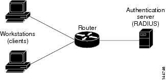
In a wireless LAN configuration, the 802.1x interface is configured in multihost mode, which is authorized as soon as one client is authenticated. After the interface is authorized, all other clients indirectly attached to the interface are granted access to the network. If the port becomes unauthorized (either because reauthentication fails or an EAPOL-Logoff message is received), the router denies access to the network to all attached clients. In this topology, the wireless access point is a client to the router and is responsible for authenticating the clients attached to it.
Related Topics
•![]() Understanding 802.1x Device Roles
Understanding 802.1x Device Roles
•![]() 802.1x Interface Authorization States
802.1x Interface Authorization States
Defining 802.1x Policies
You configure an 802.1x policy by defining:
•![]() The AAA server group containing the AAA server that authenticates hosts that are trying to connect to the network.
The AAA server group containing the AAA server that authenticates hosts that are trying to connect to the network.
•![]() The virtual interface that carries unauthenticated traffic and the physical interface that carries authenticated traffic.
The virtual interface that carries unauthenticated traffic and the physical interface that carries authenticated traffic.
•![]() (Optional) Properties of the physical interface, including the control type, automatic reauthentication, and several timeout values.
(Optional) Properties of the physical interface, including the control type, automatic reauthentication, and several timeout values.
If the router on which you are defining the 802.1x policy is not part of a VPN (for example, if it is directly connected to the corporate network to which you want to restrict access), you must manually define an access list. You can do this by defining an access rules policy (see Working with Access Rules, page 11-17).
Before You Begin
•![]() Configure the selected router with a DHCP policy that contains two IP address pools, one for authenticated clients and one for unauthenticated clients. See Defining DHCP Policies.
Configure the selected router with a DHCP policy that contains two IP address pools, one for authenticated clients and one for unauthenticated clients. See Defining DHCP Policies.
•![]() Make sure the router can route packets to the configured AAA (RADIUS) server. You can verify this by pinging the server from the router.
Make sure the router can route packets to the configured AAA (RADIUS) server. You can verify this by pinging the server from the router.
Related Topics
•![]() Understanding 802.1x Device Roles
Understanding 802.1x Device Roles
•![]() 802.1x Interface Authorization States
802.1x Interface Authorization States
•![]() Topologies Supported by 802.1x
Topologies Supported by 802.1x
Step 1 ![]() Do one of the following:
Do one of the following:
•![]() (Device view) Select Platform > Identity > 802.1x from the Policy selector.
(Device view) Select Platform > Identity > 802.1x from the Policy selector.
•![]() (Policy view) Select Router Platform > Identity > 802.1x from the Policy Type selector. Select an existing policy or create a new one.
(Policy view) Select Router Platform > Identity > 802.1x from the Policy Type selector. Select an existing policy or create a new one.
The 802.1x page is displayed. See Table J-77 on page J-129 for a description of the fields on this page.
Step 2 ![]() Enter the name of the AAA server group containing the AAA server to use for authenticating clients using 802.1x, or click Select to display a selector (see Object Selectors, page F-205). The selected AAA server must use RADIUS with EAP extensions.
Enter the name of the AAA server group containing the AAA server to use for authenticating clients using 802.1x, or click Select to display a selector (see Object Selectors, page F-205). The selected AAA server must use RADIUS with EAP extensions.
Tip ![]() If the required AAA server group is not listed in the selector, click the Create button or the Edit button to open the AAA Server Group Dialog Box, page F-6. From here you can define a AAA server group to use in the policy.
If the required AAA server group is not listed in the selector, click the Create button or the Edit button to open the AAA Server Group Dialog Box, page F-6. From here you can define a AAA server group to use in the policy.
Note ![]() Each AAA server in the selected group must be configured to communicate with an interface that exists on the router; otherwise, validation fails.
Each AAA server in the selected group must be configured to communicate with an interface that exists on the router; otherwise, validation fails.
Step 3 ![]() In the Virtual Template field, enter the name of the interface or interface role that serves as the entrusted, virtual interface for carrying unauthenticated traffic, or click Select to display a selector (see Object Selectors, page F-205). For more information, see Specifying Interfaces During Policy Definition, page 8-35.
In the Virtual Template field, enter the name of the interface or interface role that serves as the entrusted, virtual interface for carrying unauthenticated traffic, or click Select to display a selector (see Object Selectors, page F-205). For more information, see Specifying Interfaces During Policy Definition, page 8-35.
Note ![]() Integrated Services Routers (ISRs), such as the Cisco 800, 1800, 2800, and 3800 Series, automatically use VLANs to carry unauthenticated traffic. If you define a virtual template, however, it is used in place of the VLAN.
Integrated Services Routers (ISRs), such as the Cisco 800, 1800, 2800, and 3800 Series, automatically use VLANs to carry unauthenticated traffic. If you define a virtual template, however, it is used in place of the VLAN.
Note ![]() Deployment might fail if PPP is defined on the virtual template defined here. See Defining PPP Connections.
Deployment might fail if PPP is defined on the virtual template defined here. See Defining PPP Connections.
Step 4 ![]() Enter the name of the interface or interface role that serves as the trusted, physical interface for carrying authenticated traffic, or click Select to display a selector. For more information, see Specifying Interfaces During Policy Definition, page 8-35.
Enter the name of the interface or interface role that serves as the trusted, physical interface for carrying authenticated traffic, or click Select to display a selector. For more information, see Specifying Interfaces During Policy Definition, page 8-35.
The interface role you select should represent the internal protected interface that was configured as part of the VPN topology and no other physical interface on the selected router. For more information, see Defining the Endpoints and Protected Networks, page 9-20.
Tip ![]() If the interface roles you want are not listed in the selectors, click the Create button or the Edit button to open the Interface Role Dialog Box, page F-56. From here you can define interface roles to use in the policy.
If the interface roles you want are not listed in the selectors, click the Create button or the Edit button to open the Interface Role Dialog Box, page F-56. From here you can define interface roles to use in the policy.
Step 5 ![]() (Optional) Modify the defaults of the physical interface used for 802.1x authentication. See Table J-77 on page J-129 for details.
(Optional) Modify the defaults of the physical interface used for 802.1x authentication. See Table J-77 on page J-129 for details.
Network Admission Control on Cisco IOS Routers
Network Admission Control (NAC), an industry initiative sponsored by Cisco Systems, uses the network infrastructure to enforce security-policy compliance on all devices seeking to access network computing resources, thereby limiting damage from viruses and worms. By using NAC, organizations can provide network access to endpoint devices such as PCs, PDAs, and servers that are verified to be fully compliant with established security policy. NAC can also identify noncompliant devices and deny them access, place them in a quarantined area, or give them restricted access to computing resources.
Network access decisions are made through a process of posture validation, which evaluates the posture credentials presented by the endpoint device. These credentials can include such information as the endpoint's antivirus state, operating system version, operating system patch level, or Cisco Security Agent version and settings.
You can use NAC to enforce security policy compliance in many types of deployments, including branch offices, remote access, and dial-in access.
NAC policies in Security Manager enable a Cisco IOS router to act as a Network Access Device (NAD) for enforcing policy compliance on devices seeking to access the network. The following topics describe additional details about NAC:
•![]() Understanding NAC System Flow
Understanding NAC System Flow
The following topics describe the tasks you perform to create NAC policies on Cisco IOS routers:
•![]() Defining NAC Setup Parameters
Defining NAC Setup Parameters
•![]() Defining NAC Interface Parameters
Defining NAC Interface Parameters
•![]() Defining NAC Identity Parameters
Defining NAC Identity Parameters
Router Platforms Supporting NAC
To configure NAC policies on a router, the router must be running Cisco IOS Software Release 12.3(8)T images and higher (with the Advanced Security feature set). However, the following routers do not support NAC:
•![]() Cisco 7600 Series (7603, 7604, 7606, 7609, 7613)
Cisco 7600 Series (7603, 7604, 7606, 7609, 7613)
•![]() Cisco 7300 Series (7301, 7304)
Cisco 7300 Series (7301, 7304)
•![]() Cisco 7100 Series VPN Routers (7120, 7140, 7160)
Cisco 7100 Series VPN Routers (7120, 7140, 7160)
•![]() Cisco 3600 Series Multiservice Platforms (3620, 3631, 3661, 3662)
Cisco 3600 Series Multiservice Platforms (3620, 3631, 3661, 3662)
•![]() Cisco 1700 Series Modular Access Routers (1710, 1720, 1750)
Cisco 1700 Series Modular Access Routers (1710, 1720, 1750)
•![]() Cisco 1600 Series (1601, 1602, 1603, 1604, 1605)
Cisco 1600 Series (1601, 1602, 1603, 1604, 1605)
•![]() Cisco ASR 1000 Series Aggregation Services Routers (all models)
Cisco ASR 1000 Series Aggregation Services Routers (all models)
•![]() Cisco 800 Series (801, 803, 805, 811, 813, 828, 851, 857, 871, 876, 877, 878)
Cisco 800 Series (801, 803, 805, 811, 813, 828, 851, 857, 871, 876, 877, 878)
•![]() Cisco SOHO 90 Series Secure Broadband Routers (91, 96, 97)
Cisco SOHO 90 Series Secure Broadband Routers (91, 96, 97)
•![]() Cisco SOHO 77 Series (71, 76, 77 ADSL, 77 H ADSL, 78)
Cisco SOHO 77 Series (71, 76, 77 ADSL, 77 H ADSL, 78)
Understanding NAC Components
NAC contains the following components:
•![]() Cisco Trust Agent (CTA)—The CTA acts as the NAC client. It provides posture credentials for the endpoint device on which it is installed, including the type of operating system and the version of antivirus software installed.
Cisco Trust Agent (CTA)—The CTA acts as the NAC client. It provides posture credentials for the endpoint device on which it is installed, including the type of operating system and the version of antivirus software installed.
•![]() Network access device (NAD)—The NAD initiates posture validation with the CTA when its Intercept ACL is triggered. It relays posture credentials received from the CTA to a AAA server. In return, the NAD receives configuration information from the AAA server, which it enforces on the selected interface. The NAD also:
Network access device (NAD)—The NAD initiates posture validation with the CTA when its Intercept ACL is triggered. It relays posture credentials received from the CTA to a AAA server. In return, the NAD receives configuration information from the AAA server, which it enforces on the selected interface. The NAD also:
–![]() Periodically polls the CTA to confirm that it is communicating with the same client at this IP address.
Periodically polls the CTA to confirm that it is communicating with the same client at this IP address.
–![]() Revalidates all current sessions.
Revalidates all current sessions.
–![]() Sends username and password information from devices lacking a CTA (clientless hosts) to the AAA server for authentication.
Sends username and password information from devices lacking a CTA (clientless hosts) to the AAA server for authentication.
–![]() Supports an exception list of predefined actions applied to specific devices, based on the device IP address or MAC address.
Supports an exception list of predefined actions applied to specific devices, based on the device IP address or MAC address.
When you configure NAC policies in Security Manager, you are configuring the behavior of the Cisco IOS router acting as the NAD.
•![]() AAA server—The AAA server obtains and validates posture credentials received from the CTA and returns the access policy to be enforced on the NAD. The AAA server must be a Cisco Secure Access Control Server (ACS), running the RADIUS protocol. Existing ACS authorization support can be used to provide access to clientless hosts. Posture validation rules and the access policies resulting from those rules are configured on the ACS.
AAA server—The AAA server obtains and validates posture credentials received from the CTA and returns the access policy to be enforced on the NAD. The AAA server must be a Cisco Secure Access Control Server (ACS), running the RADIUS protocol. Existing ACS authorization support can be used to provide access to clientless hosts. Posture validation rules and the access policies resulting from those rules are configured on the ACS.
Related Topics
•![]() Understanding NAC System Flow
Understanding NAC System Flow
•![]() Network Admission Control on Cisco IOS Routers
Network Admission Control on Cisco IOS Routers
Understanding NAC System Flow
As shown in Figure 13-9, the system flow for NAC is:
1. ![]() An IP packet from a connecting device triggers the Intercept ACL configured on the NAD.
An IP packet from a connecting device triggers the Intercept ACL configured on the NAD.
2. ![]() The NAD triggers posture validation with the CTA configured on the device using the Extensible Authentication Protocol over User Datagram Protocol, otherwise known as EAP over UDP, or simply EoU.
The NAD triggers posture validation with the CTA configured on the device using the Extensible Authentication Protocol over User Datagram Protocol, otherwise known as EAP over UDP, or simply EoU.
3. ![]() The CTA sends its posture credentials to the NAD using EAP over UDP.
The CTA sends its posture credentials to the NAD using EAP over UDP.
4. ![]() The NAD sends these posture credentials to the ACS using RADIUS.
The NAD sends these posture credentials to the ACS using RADIUS.
5. ![]() The ACS performs posture validation, which determines whether to allow the device to access the network. (If necessary, the ACS requests additional posture validation from a third-party server. For example, if the CTA forwards credentials that are specific to a particular antivirus application, the ACS forwards this information via the HCAP protocol to a vendor server for validation.) If the device is a clientless host, the ACS checks the username and password it receives against its locally stored list.
The ACS performs posture validation, which determines whether to allow the device to access the network. (If necessary, the ACS requests additional posture validation from a third-party server. For example, if the CTA forwards credentials that are specific to a particular antivirus application, the ACS forwards this information via the HCAP protocol to a vendor server for validation.) If the device is a clientless host, the ACS checks the username and password it receives against its locally stored list.
6. ![]() The ACS directs the NAD to enforce the appropriate access policy on the requesting device. Access may be granted, denied, redirected, or restricted.
The ACS directs the NAD to enforce the appropriate access policy on the requesting device. Access may be granted, denied, redirected, or restricted.
Figure 13-9 NAC System Flow
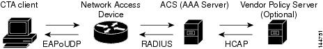
Related Topics
•![]() Network Admission Control on Cisco IOS Routers
Network Admission Control on Cisco IOS Routers
Defining NAC Setup Parameters
You configure NAC setup parameters by selecting the AAA server groups that obtain and validate the posture credentials received from devices trying to connect to the network. You can configure an option that allows devices lacking the Cisco Trust Agent (CTA) to be authenticated by a predefined username and password stored on a Cisco Secure Access Control Server (ACS). Additionally, you can modify default settings for EAP over UDP. This is the protocol used for posture validation communications between the Cisco IOS router serving as the network access device (NAD) and the device trying to access your network.
Related Topics
•![]() Defining NAC Interface Parameters
Defining NAC Interface Parameters
•![]() Defining NAC Identity Parameters
Defining NAC Identity Parameters
•![]() Network Admission Control on Cisco IOS Routers
Network Admission Control on Cisco IOS Routers
Step 1 ![]() Do one of the following:
Do one of the following:
•![]() (Device view) Select Platform > Identity > Network Admission Control from the Policy selector, then click the Setup tab in the work area.
(Device view) Select Platform > Identity > Network Admission Control from the Policy selector, then click the Setup tab in the work area.
•![]() (Policy view) Select Router Platform > Identity > Network Admission Control from the Policy Type selector. Select an existing policy or create a new one, and then click the Setup tab.
(Policy view) Select Router Platform > Identity > Network Admission Control from the Policy Type selector. Select an existing policy or create a new one, and then click the Setup tab.
The NAC Setup tab is displayed. See Table J-78 on page J-132 for a description of the fields on this tab.
Step 2 ![]() Enter the name of the AAA server group containing the AAA server that performs posture validation, or click Select to display a selector (see Object Selectors, page F-205). The selected AAA server group must contain ACS devices running RADIUS.
Enter the name of the AAA server group containing the AAA server that performs posture validation, or click Select to display a selector (see Object Selectors, page F-205). The selected AAA server group must contain ACS devices running RADIUS.
Tip ![]() If the required AAA server group is not listed in the selector, click the Create button or the Edit button to open the AAA Server Group Dialog Box, page F-6. From here you can define a AAA server group to use in the policy.
If the required AAA server group is not listed in the selector, click the Create button or the Edit button to open the AAA Server Group Dialog Box, page F-6. From here you can define a AAA server group to use in the policy.
Note ![]() Each AAA server in the selected group must be configured to communicate with an interface that exists on the router; otherwise, validation fails.
Each AAA server in the selected group must be configured to communicate with an interface that exists on the router; otherwise, validation fails.
Step 3 ![]() (Optional) Select up to two AAA server groups as backups to the main server group. If all the servers in the main server group go down, the servers in the backup server group perform NAC.
(Optional) Select up to two AAA server groups as backups to the main server group. If all the servers in the main server group go down, the servers in the backup server group perform NAC.
Both backup server groups must consist of ACS devices running RADIUS.
Step 4 ![]() (Optional) Under EAP over UDP, select one or both of the following Allow parameters:
(Optional) Under EAP over UDP, select one or both of the following Allow parameters:
a. ![]() Select the Allow IP Station ID check box to include IP addresses in the RADIUS requests sent to the ACS.
Select the Allow IP Station ID check box to include IP addresses in the RADIUS requests sent to the ACS.
b. ![]() Select the Allow Clientless check box to provide access to devices that do not have the CTA installed. In such cases, the ACS authenticates these devices by checking the username and password against a predefined list.
Select the Allow Clientless check box to provide access to devices that do not have the CTA installed. In such cases, the ACS authenticates these devices by checking the username and password against a predefined list.
If you do not select this check box, devices without CTA are prevented from accessing the network if their traffic matches the Intercept ACL. This is because without CTA, posture validation cannot be performed.
Note ![]() This feature is not supported on routers running Cisco IOS Software Release 12.4(6)T or later.
This feature is not supported on routers running Cisco IOS Software Release 12.4(6)T or later.
Step 5 ![]() (Optional) Under EAP over UDP, modify the default settings related to the EAP over UDP (EoU) protocol, if required. See Table J-78 on page J-132 for details.
(Optional) Under EAP over UDP, modify the default settings related to the EAP over UDP (EoU) protocol, if required. See Table J-78 on page J-132 for details.
Defining NAC Interface Parameters
You configure NAC interface parameters by selecting the interfaces on which NAC is performed. You must also define the Intercept ACL, which determines which traffic on these interfaces is subject to posture validation. Additionally, you can optionally override the device-level setting for initiating EAP over UDP sessions and subject all sessions to periodic revalidation (see Defining NAC Setup Parameters).
A NAC policy must include at least one interface definition to function.
Before You Begin
•![]() Select the AAA server group containing the ACS device performing posture validation. See Defining NAC Setup Parameters.
Select the AAA server group containing the ACS device performing posture validation. See Defining NAC Setup Parameters.
•![]() Define an ACL object that defines the traffic to subject to posture validation in NAC policies. See Creating Access Control List Objects, page 8-23.
Define an ACL object that defines the traffic to subject to posture validation in NAC policies. See Creating Access Control List Objects, page 8-23.
•![]() Define an ACL object that defines the default access on the selected interface (default ACL). See Creating Access Control List Objects, page 8-23.
Define an ACL object that defines the default access on the selected interface (default ACL). See Creating Access Control List Objects, page 8-23.
Related Topics
•![]() Defining NAC Setup Parameters
Defining NAC Setup Parameters
•![]() Defining NAC Identity Parameters
Defining NAC Identity Parameters
•![]() Network Admission Control on Cisco IOS Routers
Network Admission Control on Cisco IOS Routers
Step 1 ![]() Do one of the following:
Do one of the following:
•![]() (Device view) Select Platform > Identity > Network Admission Control from the Policy selector, then click the Interfaces tab in the work area.
(Device view) Select Platform > Identity > Network Admission Control from the Policy selector, then click the Interfaces tab in the work area.
•![]() (Policy view) Select Router Platform > Identity > Network Admission Control from the Policy Type selector. Select an existing policy or create a new one, and then click the Interfaces tab.
(Policy view) Select Router Platform > Identity > Network Admission Control from the Policy Type selector. Select an existing policy or create a new one, and then click the Interfaces tab.
The NAC Interfaces tab is displayed. See Table J-79 on page J-134 for a description of the fields on this tab.
Step 2 ![]() On the NAC Interfaces tab, select an interface definition from the table, then click Edit, or click Add to create a definition. The NAC Interface Configuration dialog box appears. See Table J-80 on page J-135 for a description of the fields in this dialog box.
On the NAC Interfaces tab, select an interface definition from the table, then click Edit, or click Add to create a definition. The NAC Interface Configuration dialog box appears. See Table J-80 on page J-135 for a description of the fields in this dialog box.
Step 3 ![]() Enter the name of the interface or interface role on which NAC is performed, or click Select to display a selector (see Object Selectors, page F-205). For more information, see Specifying Interfaces During Policy Definition, page 8-35.
Enter the name of the interface or interface role on which NAC is performed, or click Select to display a selector (see Object Selectors, page F-205). For more information, see Specifying Interfaces During Policy Definition, page 8-35.
Tip ![]() If the interface roles you want are not listed in the selectors, click the Create button to create it.
If the interface roles you want are not listed in the selectors, click the Create button to create it.
Step 4 ![]() (Optional) Enter the name of the ACL object that acts as the intercept ACL, or click Select to display a selector (see Object Selectors, page F-205).
(Optional) Enter the name of the ACL object that acts as the intercept ACL, or click Select to display a selector (see Object Selectors, page F-205).
The intercept ACL determines which traffic on the selected interfaces is subject to posture validation before being granted access to the network. If you do not select an ACL, all traffic on the selected interfaces is subject to posture validation.
Note ![]() If the required ACL is not listed in the selector, click the Create button to create it.
If the required ACL is not listed in the selector, click the Create button to create it.
Note ![]() If you defined an authentication proxy on the same interface as a NAC interface, you must use the same intercept ACL in both policies. Otherwise, deployment might fail. For more information about authentication proxies, see Configuring Settings for AAA (IOS), page 11-44.
If you defined an authentication proxy on the same interface as a NAC interface, you must use the same intercept ACL in both policies. Otherwise, deployment might fail. For more information about authentication proxies, see Configuring Settings for AAA (IOS), page 11-44.
Step 5 ![]() (Optional) To override the device-level value defined for maximum attempts to initiate an EAP over UDP session, enter a new value in the EAP over UDP Max Retries field.
(Optional) To override the device-level value defined for maximum attempts to initiate an EAP over UDP session, enter a new value in the EAP over UDP Max Retries field.
Step 6 ![]() (Optional) Deselect the Enable EOU Session Revalidation check box if you do not want the NAD to periodically revalidate all EAP over UDP sessions.
(Optional) Deselect the Enable EOU Session Revalidation check box if you do not want the NAD to periodically revalidate all EAP over UDP sessions.
Note ![]() Subinterfaces support default values only for the options described in Step 5 and Step 6.
Subinterfaces support default values only for the options described in Step 5 and Step 6.
Step 7 ![]() Click OK to save your definitions locally on the client and close the dialog box. Your interface definitions appear in the table on the NAC Interfaces tab.
Click OK to save your definitions locally on the client and close the dialog box. Your interface definitions appear in the table on the NAC Interfaces tab.
Defining NAC Identity Parameters
By default, any traffic over the selected interfaces that match the intercept ACL is subjected to posture validation before it is permitted to enter the network. However, you can create an exception list of predefined actions to apply to specific devices. You use identity profiles to create this exception list. Each profile contains two elements:
•![]() A profile definition, identifies the device to which the profile applies. Devices can be identified by their IP addresses, MAC addresses, or types (for Cisco IP phones).
A profile definition, identifies the device to which the profile applies. Devices can be identified by their IP addresses, MAC addresses, or types (for Cisco IP phones).
•![]() An action, which defines the result when this device tries to access the network. Each action can include an ACL, a redirect URL, or both. If you do not specify an action, the default ACL is applied.
An action, which defines the result when this device tries to access the network. Each action can include an ACL, a redirect URL, or both. If you do not specify an action, the default ACL is applied.
When you configure NAC identity parameters, you first define one or more identity actions and then create the identity profiles to which these actions apply. You can apply each action to multiple profiles.
Related Topics
•![]() Defining NAC Setup Parameters
Defining NAC Setup Parameters
•![]() Defining NAC Interface Parameters
Defining NAC Interface Parameters
•![]() Network Admission Control on Cisco IOS Routers
Network Admission Control on Cisco IOS Routers
Step 1 ![]() Do one of the following:
Do one of the following:
•![]() (Device view) Select Platform > Identity > Network Admission Control from the Policy selector, then click the Identities tab in the work area.
(Device view) Select Platform > Identity > Network Admission Control from the Policy selector, then click the Identities tab in the work area.
•![]() (Policy view) Select Router Platform > Identity > Network Admission Control from the Policy Type selector. Select an existing policy or create a new one, and then click the Identities tab.
(Policy view) Select Router Platform > Identity > Network Admission Control from the Policy Type selector. Select an existing policy or create a new one, and then click the Identities tab.
The NAC Identities tab is displayed. See Table J-81 on page J-136 for a description of the fields on this tab.
Step 2 ![]() Define one or more identity actions:
Define one or more identity actions:
a. ![]() On the NAC Identities tab, select an identity action from the lower table, then click Add. The NAC Identity Action dialog box appears.
On the NAC Identities tab, select an identity action from the lower table, then click Add. The NAC Identity Action dialog box appears.
b. ![]() Define an identity action. See Table J-83 on page J-138 for a description of the available fields.
Define an identity action. See Table J-83 on page J-138 for a description of the available fields.
c. ![]() Click OK to save your definitions and close the dialog box. The action appears in the Identity Actions table in the NAC Identities tab.
Click OK to save your definitions and close the dialog box. The action appears in the Identity Actions table in the NAC Identities tab.
d. ![]() (Optional) Repeat a.through c. to define additional identity actions, as required.
(Optional) Repeat a.through c. to define additional identity actions, as required.
Step 3 ![]() Define identity profiles:
Define identity profiles:
a. ![]() Select an identity profile from the upper table on the NAC Identities tab, then click Add. The NAC Identity Profile dialog box appears. See Table J-82 on page J-137 for a description of the fields in this dialog box.
Select an identity profile from the upper table on the NAC Identities tab, then click Add. The NAC Identity Profile dialog box appears. See Table J-82 on page J-137 for a description of the fields in this dialog box.
b. ![]() Enter the name of an identity action (as defined in Step 2) or click Select to display a selector.
Enter the name of an identity action (as defined in Step 2) or click Select to display a selector.
c. ![]() Select and define a profile definition, which identifies the device to which the profile should apply.
Select and define a profile definition, which identifies the device to which the profile should apply.
d. ![]() Click OK to save your definitions and close the dialog box. The profile appears in the Identity Profiles table in the NAC Identities tab.
Click OK to save your definitions and close the dialog box. The profile appears in the Identity Profiles table in the NAC Identities tab.
e. ![]() (Optional) Repeat a. through d. to define additional identity profiles, as required.
(Optional) Repeat a. through d. to define additional identity profiles, as required.
Logging on Cisco IOS Routers
Security Manager provides the following policies for configuring logging on a Cisco IOS router:
•![]() Syslog Logging Setup—Enable the syslog-logging feature, and define basic logging parameters. For more information, see Defining Syslog Logging Setup Parameters.
Syslog Logging Setup—Enable the syslog-logging feature, and define basic logging parameters. For more information, see Defining Syslog Logging Setup Parameters.
•![]() Syslog Servers—Define the remote servers to which syslog messages are sent. For more information, see Defining Syslog Servers.
Syslog Servers—Define the remote servers to which syslog messages are sent. For more information, see Defining Syslog Servers.
•![]() NetFlow—Enable NetFlow logging by providing parameters and interfaces. See Defining NetFlow Parameters for more information.
NetFlow—Enable NetFlow logging by providing parameters and interfaces. See Defining NetFlow Parameters for more information.
Note ![]() We strongly recommend configuring a Network Time Protocol (NTP) policy on all routers on which logging is enabled. NTP synchronization provides accurate timestamps for syslog messages, which is essential for comparing logs on multiple devices.
We strongly recommend configuring a Network Time Protocol (NTP) policy on all routers on which logging is enabled. NTP synchronization provides accurate timestamps for syslog messages, which is essential for comparing logs on multiple devices.
Defining Syslog Logging Setup Parameters
This procedure describes enabling syslog logging on the router, and defining which messages are sent to a syslog server. In addition, you can optionally define:
•![]() The source interface for all syslog messages sent from this device.
The source interface for all syslog messages sent from this device.
•![]() The messages that are saved to a local buffer.
The messages that are saved to a local buffer.
•![]() An origin identifier added to each message.
An origin identifier added to each message.
•![]() A rate limit on the number of messages that can be sent.
A rate limit on the number of messages that can be sent.
Note ![]() To send syslog messages from the router to a syslog server, you must also define the IP address of the syslog server. For more information, see Defining Syslog Servers.
To send syslog messages from the router to a syslog server, you must also define the IP address of the syslog server. For more information, see Defining Syslog Servers.
Related Topics
•![]() Understanding Log Message Severity Levels
Understanding Log Message Severity Levels
Step 1 ![]() Do one of the following to access the router's Syslog Logging Setup page:
Do one of the following to access the router's Syslog Logging Setup page:
•![]() (Device view) Select Platform > Logging > Syslog Logging Setup from the Policy selector.
(Device view) Select Platform > Logging > Syslog Logging Setup from the Policy selector.
•![]() (Policy view) Select Router Platform > Logging > Syslog Logging Setup from the Policy Type selector. Select an existing policy or create a new one.
(Policy view) Select Router Platform > Logging > Syslog Logging Setup from the Policy Type selector. Select an existing policy or create a new one.
The Syslog Logging Setup page is displayed. See Table J-84 on page J-139 for a description of the fields on this page.
Step 2 ![]() Select Enable Logging to turn on the syslog logging feature. If this option is not selected, no log messages are created.
Select Enable Logging to turn on the syslog logging feature. If this option is not selected, no log messages are created.
Tip ![]() To use the device's default logging settings, or to restore the default settings, simply select Enable Logging, ensure all other fields are blank, then click Save. The default settings vary by device. See your router documentation for more details.
To use the device's default logging settings, or to restore the default settings, simply select Enable Logging, ensure all other fields are blank, then click Save. The default settings vary by device. See your router documentation for more details.
Step 3 ![]() (Optional) In the Source Interface field, enter the name of the interface or interface role whose address should be used as the source interface for all log messages sent to a syslog server; or click Select to display an interface selector (see Object Selectors, page F-205). The source interface must have an IP address.
(Optional) In the Source Interface field, enter the name of the interface or interface role whose address should be used as the source interface for all log messages sent to a syslog server; or click Select to display an interface selector (see Object Selectors, page F-205). The source interface must have an IP address.
Tip ![]() If the required interface role is not listed, click the Create button or the Edit button in the selector to open the Interface Role Dialog Box, page F-56, where you can define an interface role to use in the policy.
If the required interface role is not listed, click the Create button or the Edit button in the selector to open the Interface Role Dialog Box, page F-56, where you can define an interface role to use in the policy.
This option is useful when the syslog server cannot reach the address from which the connection originated (for example, due to a firewall). If you do not enter a value in this field, the address of the outgoing interface is used.
Step 4 ![]() (Optional) To send log messages to a syslog server:
(Optional) To send log messages to a syslog server:
a. ![]() Select Enable Trap. This option is selected by default.
Select Enable Trap. This option is selected by default.
b. ![]() Select a value from the Trap Level list. All messages of this severity or greater (that is, having the same or a lower severity-level number) are sent to the syslog server; messages of a lesser severity are ignored. For more information about severity levels, see Table 13-5.
Select a value from the Trap Level list. All messages of this severity or greater (that is, having the same or a lower severity-level number) are sent to the syslog server; messages of a lesser severity are ignored. For more information about severity levels, see Table 13-5.
Step 5 ![]() (Optional) To save log messages locally to a buffer on the router:
(Optional) To save log messages locally to a buffer on the router:
a. ![]() Select Enable Buffer. This option is selected by default.
Select Enable Buffer. This option is selected by default.
b. ![]() Enter the Buffer Size in bytes.
Enter the Buffer Size in bytes.
c. ![]() Select the lowest severity level for messages to be saved to the buffer. All messages of that severity level or greater are saved to the buffer.
Select the lowest severity level for messages to be saved to the buffer. All messages of that severity level or greater are saved to the buffer.
d. ![]() Select Use XML Format to save messages in XML format. (You can configure both the regular buffer and the XML buffer in the same policy.) If you select this option, enter the size of the XML buffer in bytes.
Select Use XML Format to save messages in XML format. (You can configure both the regular buffer and the XML buffer in the same policy.) If you select this option, enter the size of the XML buffer in bytes.
Note ![]() Make sure not to make buffers so large that the router runs out of memory for other tasks. If this happens, deployment may fail.
Make sure not to make buffers so large that the router runs out of memory for other tasks. If this happens, deployment may fail.
Step 6 ![]() (Optional) Define a rate limit to prevent a flood of output messages:
(Optional) Define a rate limit to prevent a flood of output messages:
a. ![]() Select Enable Rate Limit. This option is selected by default.
Select Enable Rate Limit. This option is selected by default.
b. ![]() Enter the maximum number of messages that can be sent per second.
Enter the maximum number of messages that can be sent per second.
c. ![]() Select the severity levels to exclude from the rate limit. For example, if you select 2 (critical), all syslog messages of severity levels 0-2 are sent to the syslog server regardless of the defined rate limit.
Select the severity levels to exclude from the rate limit. For example, if you select 2 (critical), all syslog messages of severity levels 0-2 are sent to the syslog server regardless of the defined rate limit.
d. ![]() Select All Messages to apply the rate limit to all syslog messages except console messages (and excepting those severity levels specifically excluded above).
Select All Messages to apply the rate limit to all syslog messages except console messages (and excepting those severity levels specifically excluded above).
e. ![]() Select Console Messages to apply the rate limit to console messages only.
Select Console Messages to apply the rate limit to console messages only.
Note ![]() If you enable rate limiting without specifying any options, the default settings (10 messages per second, applied to console messages only) are applied.
If you enable rate limiting without specifying any options, the default settings (10 messages per second, applied to console messages only) are applied.
Step 7 ![]() (Optional) To add an origin identifier to the beginning of each syslog message:
(Optional) To add an origin identifier to the beginning of each syslog message:
a. ![]() Select the type of origin ID to send—the IP address of the router, its host name, or a text string that you provide.
Select the type of origin ID to send—the IP address of the router, its host name, or a text string that you provide.
b. ![]() If you select String, enter the desired text in the field provided. Spaces are permitted.
If you select String, enter the desired text in the field provided. Spaces are permitted.
The origin identifier is useful for identifying the source of syslog messages in cases where you send output from multiple devices to a single syslog server.
Note ![]() The origin identifier is not added to messages sent to local destinations, such as the buffer, the console, and the monitor.
The origin identifier is not added to messages sent to local destinations, such as the buffer, the console, and the monitor.
Defining Syslog Servers
This procedure describes how to define the servers to which the router should send syslog messages. When you define a syslog server, you can choose whether the logging messages it receives should be forwarded as plain text or in XML format.
If you define multiple syslog servers, logging messages are sent to all of them.
Before You Begin
•![]() Enable syslog logging and define basic logging parameters on the Syslog Logging Setup page. For more information, see Defining Syslog Logging Setup Parameters.
Enable syslog logging and define basic logging parameters on the Syslog Logging Setup page. For more information, see Defining Syslog Logging Setup Parameters.
Related Topics
•![]() Defining Syslog Logging Setup Parameters
Defining Syslog Logging Setup Parameters
•![]() Understanding Log Message Severity Levels
Understanding Log Message Severity Levels
Step 1 ![]() Do one of the following to access the router's Syslog Servers page:
Do one of the following to access the router's Syslog Servers page:
•![]() (Device view) Select Platform > Logging > Syslog Servers from the Policy selector.
(Device view) Select Platform > Logging > Syslog Servers from the Policy selector.
•![]() (Policy view) Select Router Platform > Logging > Syslog Servers from the Policy Type selector. Select an existing policy or create a new one.
(Policy view) Select Router Platform > Logging > Syslog Servers from the Policy Type selector. Select an existing policy or create a new one.
The Syslog Servers page is displayed. See Table J-85 on page J-142 for a description of the fields on this page.
Step 2 ![]() To define a server to receive syslog messages from this router, click the Add button below the table to open the Syslog Server dialog box. See Table J-86 on page J-143 for more about this dialog box.
To define a server to receive syslog messages from this router, click the Add button below the table to open the Syslog Server dialog box. See Table J-86 on page J-143 for more about this dialog box.
Step 3 ![]() In the IP Address field, enter the address of the desired syslog server, or click Select to display a host selector (see Object Selectors, page F-205). For more information, see Specifying IP Addresses During Policy Definition, page 8-68.
In the IP Address field, enter the address of the desired syslog server, or click Select to display a host selector (see Object Selectors, page F-205). For more information, see Specifying IP Addresses During Policy Definition, page 8-68.
Tip ![]() If the host you want is not listed in the selector, click the Create button or the Edit button to display the Add or Edit Network/Host Dialog Box, page F-141. From here you can create a network/host object to use in the policy.
If the host you want is not listed in the selector, click the Create button or the Edit button to display the Add or Edit Network/Host Dialog Box, page F-141. From here you can create a network/host object to use in the policy.
Step 4 ![]() (Optional) Select Forward Messages in XML Format to forward received syslog messages in XML format instead of plain text.
(Optional) Select Forward Messages in XML Format to forward received syslog messages in XML format instead of plain text.
Step 5 ![]() Click OK to save your definition and close the dialog box. The syslog server you defined is displayed in the table.
Click OK to save your definition and close the dialog box. The syslog server you defined is displayed in the table.
Note ![]() To edit a syslog server, select it from the table, then click Edit. To remove a syslog server, select it, then click Delete.
To edit a syslog server, select it from the table, then click Edit. To remove a syslog server, select it, then click Delete.
Understanding Log Message Severity Levels
Syslog messages on Cisco IOS routers are classified into eight severity levels. Each severity level is identified by a number and a corresponding name. The lower the number, the greater the severity, as shown in the following table.
Related Topics
•![]() Defining Syslog Logging Setup Parameters
Defining Syslog Logging Setup Parameters
NetFlow on Cisco IOS Routers
The ability to characterize IP traffic and understand how and where it flows is critical for network availability, performance and troubleshooting. Monitoring IP traffic flows facilitates accurate capacity planning, and ensures that network resources are used appropriately in support of organizational goals.
NetFlow is a logging feature available on IOS devices for recording, caching and transmitting IP traffic-flow information on a per-interface basis. The basic output of NetFlow is a flow record, where a "flow" is defined as a unidirectional stream of packets between a given source and destination—both defined by a network-layer IP address and transport-layer source and destination port numbers.
On the IOS device, NetFlow consists of two key components—a NetFlow cache which stores IP flow data, and the NetFlow export mechanism that transmits the NetFlow records to a collection server for data reporting. Thus, when enabled, NetFlow records and caches statistics for incoming and outgoing traffic flows, periodically transmitting these records from the device to a NetFlow collector, in the form of User Datagram Protocol (UDP) datagrams.
Several different formats for the export packet, or flow record, have evolved as NetFlow has matured, and these formats are commonly referred to as the NetFlow version. These versions are well documented, and include versions 1, 5, 7, and 9. The most commonly used format is NetFlow version 5, but version 9 is the latest format and has some advantages for extensibility, security, traffic analysis and multicasting.
Security Manager currently supports Traditional NetFlow on IOS devices. Traditional NetFlow provides a fixed flow record, even for version 9, meaning the device will use certain flags and predefined record combinations in generating the flow. The device configuration settings define export destinations, export interface, and certain version-specific transmission options.
More About Traffic Flows and NetFlow
Each packet that passes into or out of a router or switch is examined for a set of IP packet attributes. These attributes are the IP packet identity or "fingerprint," and they define whether the packet is unique, or related to other packets.
All packets with the same source/destination IP address, source/destination ports, protocol interface, and class of service are grouped into a flow and the packets and bytes are tallied. This method of flow determination (or "fingerprinting") is scalable because a large amount of network information can be condensed into a database of NetFlow information called the NetFlow cache.
In general, the NetFlow cache is constantly filling with flows, and software in the router or switch is searching the cache for flows that have terminated or expired, and these flows are exported to the NetFlow collector. (Unlike SNMP polling, NetFlow export periodically transmits information to the NetFlow collector.) The NetFlow collector has the job of assembling and organizing the exported flows to produce the real-time or historical reports used for traffic and security analysis.
NetFlow Summary
To summarize, the following steps outline NetFlow:
•![]() NetFlow is configured on the router or switch to capture IP traffic flows
NetFlow is configured on the router or switch to capture IP traffic flows
•![]() Flow records are stored in the local NetFlow cache
Flow records are stored in the local NetFlow cache
•![]() Periodically, approximately 30 to 50 flow records are bundled together and exported to a NetFlow collector server
Periodically, approximately 30 to 50 flow records are bundled together and exported to a NetFlow collector server
•![]() The collector software creates reports from the NetFlow data
The collector software creates reports from the NetFlow data
Related Topics
•![]() NetFlow Policy Page, page J-143
NetFlow Policy Page, page J-143
Defining NetFlow Parameters
This procedure describes enabling NetFlow logging on the router.
Related Topics
•![]() NetFlow Policy Page, page J-143
NetFlow Policy Page, page J-143
Step 1 ![]() To access the router's NetFlow page, do one of the following:
To access the router's NetFlow page, do one of the following:
•![]() (Device view) Select Platform > Logging > NetFlow from the Policy selector.
(Device view) Select Platform > Logging > NetFlow from the Policy selector.
•![]() (Policy view) Select Router Platform > Logging > NetFlow from the Policy Type selector. Select an existing policy or create a new one.
(Policy view) Select Router Platform > Logging > NetFlow from the Policy Type selector. Select an existing policy or create a new one.
The router's NetFlow page is displayed. See NetFlow Policy Page, page J-143 for complete descriptions of the fields on this page.
Step 2 ![]() On the Setup tab of the NetFlow page, specify global NetFlow parameters for the router:
On the Setup tab of the NetFlow page, specify global NetFlow parameters for the router:
•![]() Primary Destination - Choose IP Address or Hostname from this list to enable NetFlow collection and to specify how the primary NetFlow collector will be defined. You can choose the blank entry to disable this option.
Primary Destination - Choose IP Address or Hostname from this list to enable NetFlow collection and to specify how the primary NetFlow collector will be defined. You can choose the blank entry to disable this option.
–![]() IP Address - Enter the IP address of the device hosting the primary NetFlow Collection Engine, and then enter the number of the UDP Port monitored by that flow collector (port numbers can range from 1 to 65535).
IP Address - Enter the IP address of the device hosting the primary NetFlow Collection Engine, and then enter the number of the UDP Port monitored by that flow collector (port numbers can range from 1 to 65535).
–![]() Hostname - Enter the fully qualified domain name of the device hosting the primary NetFlow Collection Engine, and then enter the number of the UDP Port monitored by that flow collector (port numbers can range from 1 to 65535).
Hostname - Enter the fully qualified domain name of the device hosting the primary NetFlow Collection Engine, and then enter the number of the UDP Port monitored by that flow collector (port numbers can range from 1 to 65535).
•![]() Redundant Destination - Choose IP Address or Hostname from this list to specify how the back-up NetFlow collector will be defined. You can choose the blank entry to disable this option.
Redundant Destination - Choose IP Address or Hostname from this list to specify how the back-up NetFlow collector will be defined. You can choose the blank entry to disable this option.
–![]() IP Address - Enter the IP address of the device hosting the secondary NetFlow Collection Engine, and then enter the number of the UDP Port monitored by that flow collector (port numbers can range from 1 to 65535).
IP Address - Enter the IP address of the device hosting the secondary NetFlow Collection Engine, and then enter the number of the UDP Port monitored by that flow collector (port numbers can range from 1 to 65535).
–![]() Hostname - Enter the fully qualified domain name of the device hosting the secondary NetFlow Collection Engine, and then enter the number of the UDP Port monitored by that flow collector (port numbers can range from 1 to 65535).
Hostname - Enter the fully qualified domain name of the device hosting the secondary NetFlow Collection Engine, and then enter the number of the UDP Port monitored by that flow collector (port numbers can range from 1 to 65535).
Note ![]() If you define a Primary and a Redundant Destination, flow data is transmitted to both.
If you define a Primary and a Redundant Destination, flow data is transmitted to both.
•![]() Source Interface - Specify the router interface through which flow data will be transmitted to the collector destination(s).
Source Interface - Specify the router interface through which flow data will be transmitted to the collector destination(s).
•![]() Version - Define the record format to be used for flow data by choosing the appropriate NetFlow version number from this drop-down list. You can choose the blank entry to disable this option.
Version - Define the record format to be used for flow data by choosing the appropriate NetFlow version number from this drop-down list. You can choose the blank entry to disable this option.
–![]() 1 - The original record format. No additional parameters are required.
1 - The original record format. No additional parameters are required.
–![]() 5 - The most widely adopted format; includes Border Gateway Protocol (BGP) autonomous system (AS) information and flow sequence numbers.
5 - The most widely adopted format; includes Border Gateway Protocol (BGP) autonomous system (AS) information and flow sequence numbers.
If BGP is configured on your network, you can include either origin or peer AS information in the NetFlow records. Choose origin-as or peer-as from the AS Type drop-down list. You can choose the blank entry to disable this option.
Check Enable BGP Nexthop to include BGP next hop information in the flow caches. (Note that with version 5, this information is visible in the caches, but it is not exported.)
–![]() 9 - The most-recent, template-based version; not yet fully supported.
9 - The most-recent, template-based version; not yet fully supported.
If BGP is configured on your network, you can include either origin or peer AS information in the NetFlow records. Choose origin-as or peer-as from the AS Type drop-down list. You can choose the blank entry to disable this option.
Check Enable BGP Nexthop to include BGP next hop information in the flow records.
Note ![]() AS information collection is resource intensive, especially for origin-as. If you are not interested in monitoring peering arrangements, disabling AS collection may improve performance.
AS information collection is resource intensive, especially for origin-as. If you are not interested in monitoring peering arrangements, disabling AS collection may improve performance.
Step 3 ![]() On the Interfaces tab, define the interfaces for which traffic flows are to be reported.
On the Interfaces tab, define the interfaces for which traffic flows are to be reported.
•![]() To add an interface, click the Add Row button to open the Add NetFlow Interface Settings dialog box. This dialog box is described in Adding and Editing NetFlow Interface Settings, page J-146.
To add an interface, click the Add Row button to open the Add NetFlow Interface Settings dialog box. This dialog box is described in Adding and Editing NetFlow Interface Settings, page J-146.
•![]() To edit an existing interface, select the appropriate entry in the Interfaces table and then click the Edit Row button to open the Edit NetFlow Interface Settings dialog box (described in Adding and Editing NetFlow Interface Settings, page J-146).
To edit an existing interface, select the appropriate entry in the Interfaces table and then click the Edit Row button to open the Edit NetFlow Interface Settings dialog box (described in Adding and Editing NetFlow Interface Settings, page J-146).
•![]() To delete an existing interface, select that entry in the Interfaces table and then click the Delete Row button, and then confirm the deletion.
To delete an existing interface, select that entry in the Interfaces table and then click the Delete Row button, and then confirm the deletion.
Note ![]() You can disable NetFlow data collection on an interface without deleting it. Refer to Adding and Editing NetFlow Interface Settings, page J-146 for more information.
You can disable NetFlow data collection on an interface without deleting it. Refer to Adding and Editing NetFlow Interface Settings, page J-146 for more information.
Quality of Service on Cisco IOS Routers
Quality of service (QoS) refers to the ability of a network to provide priority service to selected network traffic over various underlying technologies, including Frame Relay, ATM, Ethernet and 802.1 networks, SONET, and IP-routed networks. QoS features enhance the predictability of network service by:
•![]() Supporting dedicated bandwidth.
Supporting dedicated bandwidth.
•![]() Improving loss characteristics.
Improving loss characteristics.
•![]() Avoiding and managing network congestion.
Avoiding and managing network congestion.
•![]() Shaping network traffic.
Shaping network traffic.
•![]() Setting traffic priorities across the network.
Setting traffic priorities across the network.
QoS is generally used at entry points to service providers, as well as at consolidation points where multiple lines converge. QoS is also useful where speed mismatches occur (for example, at the boundary between a WAN and a LAN), as these places are often traffic congestion points.
QoS policies in Security Manager are based on the Cisco Systems Modular QoS CLI (MQC). MQC standardizes the CLI and semantics for QoS features across all platforms supported by Cisco IOS software, which provides a modular and highly extensible framework for deploying QoS. Security Manager provides an easy-to-use interface for MQC that concentrates key QoS features inside a single dialog box, streamlining the creation of QoS policies for selected traffic entering and leaving the router.
For a description of the procedure for defining a QoS policy in Security Manager, see Defining QoS Policies.
Related Topics
•![]() Understanding Marking Parameters
Understanding Marking Parameters
•![]() Understanding Queuing Parameters
Understanding Queuing Parameters
•![]() Understanding Policing and Shaping Parameters
Understanding Policing and Shaping Parameters
Quality of Service and CEF
Cisco Express Forwarding (CEF) is an advanced Layer 3 IP switching technology that optimizes network performance and scalability for all kinds of networks. It defines the fastest method by which a Cisco IOS router forwards packets from ingress to egress interfaces.
Certain QoS features configurable in Security Manager, such as Class-Based Policing and Class-Based Weighted Random Early Detection, are supported only on routers that run CEF. All routers from the Cisco 800 Series to the Cisco 7200 Series require CEF for these QoS features; the Cisco 7500 Series requires distributed CEF (dCEF).
Note ![]() For a complete list, see When is CEF Required for Quality of Service on Cisco.com at this URL: http://www.cisco.com/en/US/tech/tk39/tk824/technologies_tech_note09186a0080094978.shtml
For a complete list, see When is CEF Required for Quality of Service on Cisco.com at this URL: http://www.cisco.com/en/US/tech/tk39/tk824/technologies_tech_note09186a0080094978.shtml
By default, CEF is enabled as part of the router's initial configuration. To verify whether CEF is enabled on your router, use the show ip cef command. You can configure CEF using the CEF interface settings policy (see CEF Interface Settings on Cisco IOS Routers). Be aware, however, that if your router does not have CEF enabled, activating CEF could have a significant impact on your router's packet streaming. Consult your router documentation before enabling CEF.
Related Topics
•![]() Quality of Service on Cisco IOS Routers
Quality of Service on Cisco IOS Routers
Understanding Matching Parameters
You define matching parameters by identifying the traffic on which QoS is performed, that is, classifying the interesting packets. Various classification tools are available, including protocol type, IP precedence (IPP) value, Differentiated Service Code Point (DSCP) value, and ACLs.
Traffic classes consist of a series of match criteria and a means of evaluating these criteria. For example, you might define a class with matching criteria based on several specified protocols and a DSCP value. You can then specify that a packet must match only one of these defined criteria to be considered part of this class. Your other option is to specify that packets must match all defined criteria considered part of the traffic class.
Packets that are members of a defined traffic class are forwarded according to the QoS specifications that you defined in the policy map. Packets that fail to meet any of the matching criteria are classified as members of the default traffic class.
For information about defining matching parameters in a QoS policy, see Defining QoS Class Matching Parameters.
Related Topics
•![]() Quality of Service on Cisco IOS Routers
Quality of Service on Cisco IOS Routers
Understanding Marking Parameters
Marking parameters enable you to classify packets, which entails using a traffic descriptor to categorize a packet within a specific group. This defines the packet and makes it accessible for QoS handling on the network. Both traffic policers and traffic shapers use the packet classification to ensure adherence to the contracted level of service agreed upon between the source and your network. Additionally, marking parameters enable you to take packets that might have arrived at the device with one QoS classification and reclassify them. Downstream devices use this new classification to identify the packets and apply the appropriate QoS functions to them.
Security Manager uses two types of marking for IPv4 packets—one based on IPP classes and one based on DSCP values. IPP is based on the three most significant bits in the Type of Service (ToS) byte of each packet, which means you can partition traffic into eight classes. For historical reasons, each precedence value corresponds with a name, as defined in RFC 791. Table 13-6 lists the numbers and their corresponding names, from least to most important.
|
|
|
|---|---|
0 |
routine |
1 |
priority |
2 |
immediate |
3 |
flash |
4 |
flash-override |
5 |
critical |
6 |
internet |
7 |
network |
Note ![]() Classes 6 and 7 are generally reserved for network control information, such as routing updates.
Classes 6 and 7 are generally reserved for network control information, such as routing updates.
DSCP is based on the six most significant bits in the ToS byte (the remaining two bits are used for flow control), with values ranging from 0 to 63. The DSCP bits contains the IPP bits, which makes DSCP backward-compatible with IPP.
Marking is generally used on devices that are close to the network edge or administrative domain so that subsequent devices can provide service based on the classification mark.
For information about defining marking parameters in a QoS policy, see Defining QoS Class Marking Parameters.
Related Topics
•![]() Understanding Queuing Parameters
Understanding Queuing Parameters
•![]() Understanding Policing and Shaping Parameters
Understanding Policing and Shaping Parameters
•![]() Quality of Service on Cisco IOS Routers
Quality of Service on Cisco IOS Routers
Understanding Queuing Parameters
Queuing manages congestion on traffic leaving a Cisco IOS router by determining the order in which to send packets out over an interface, based on priorities you assign to those packets. Queuing makes it possible to prioritize traffic to satisfy time-critical applications, such as desktop video conferencing, while still addressing the needs of less time-dependent applications, such as file transfer.
During periods of light traffic, that is, when no congestion exists, packets are sent out as soon as they arrive at an interface. However, during periods of transmission congestion at the outgoing interface, packets arrive faster than the interface can send them. By using congestion management features such as queuing, packets accumulating at the interface are queued until the interface is free to send them. They are then scheduled for transmission according to their assigned priority and the queuing mechanism configured for the interface. The router determines the order of packet transmission by controlling which packets are placed in which queue and how queues are serviced with respect to one another.
Security Manager uses a form of queuing called Class-Based Weighted Fair Queuing (CBWFQ). With CBWFQ, you define traffic classes based on match criteria. Packets matching the criteria constitute the traffic for this class. A queue is reserved for each class, containing the traffic belonging to that class. You assign characteristics to queues, such as the bandwidth (fixed or minimum) assigned to it and the queue limit, which is the maximum number of packets allowed to accumulate in the queue.
When you use CBWFQ, the sum of all bandwidth allocation on an interface cannot exceed 75 percent of the total available interface bandwidth. The remaining 25 percent is used for other overhead, including Layer 2 overhead, routing traffic, and best-effort traffic. Bandwidth for the CBWFQ default class, for instance, is taken from the remaining 25 percent.
For more information about queuing, see:
For information about defining queuing parameters in a QoS policy, see Defining QoS Class Queuing Parameters.
Related Topics
•![]() Understanding Marking Parameters
Understanding Marking Parameters
•![]() Understanding Policing and Shaping Parameters
Understanding Policing and Shaping Parameters
•![]() Quality of Service on Cisco IOS Routers
Quality of Service on Cisco IOS Routers
Tail Drop vs. WRED
After a queue reaches its configured queue limit, the arrival of additional packets causes tail drop or packet drop to take effect, depending on how you configured the QoS policy. Tail drop, which is the default response, treats all traffic equally and does not differentiate between different classes of service. When tail drop is in effect, packets are dropped from full queues until the congestion is eliminated and the queue is no longer full. This often leads to global synchronization, in which a period of congestion is followed by a period of underutilization, as multiple TCP hosts reduce their transmission rates simultaneously.
A more sophisticated approach to managing queue congestion is offered by Cisco's implementation of Random Early Detection, called Weighted Random Early Detection, or WRED. As shown in Figure 13-10, WRED reduces the chances of tail drop by selectively dropping packets when the output interface begins to show signs of congestion. By dropping some packets early instead of waiting until the queue is full, WRED avoids dropping large numbers of packets at once and allows the transmission line to be used fully at all times.
Figure 13-10 Weighted Random Early Detection
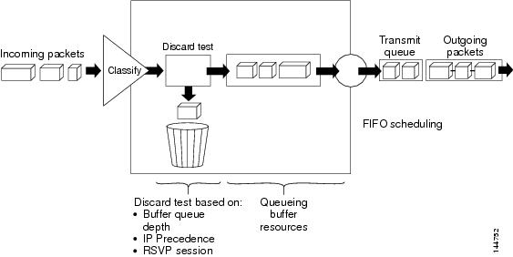
WRED is useful only when the bulk of the traffic is TCP/IP traffic, because TCP hosts reduce their transmission rate in response to congestion. With other protocols, packet sources might not respond, or might resend dropped packets at the same rate. As a result, dropping packets does not decrease congestion.
Note ![]() WRED treats non-IP traffic as precedence 0, the lowest precedence value. Therefore, non-IP traffic is more likely to be dropped than IP traffic.
WRED treats non-IP traffic as precedence 0, the lowest precedence value. Therefore, non-IP traffic is more likely to be dropped than IP traffic.
Related Topics
•![]() Understanding Queuing Parameters
Understanding Queuing Parameters
Low-Latency Queuing
The low-latency queuing (LLQ) feature brings strict priority queuing to CBWFQ. Strict priority queuing gives delay-sensitive data, such as voice traffic, preference over other traffic.
Note ![]() Although it is possible to assign various types of real-time traffic to the strict priority queue, we strongly recommend that you direct only voice traffic to it.
Although it is possible to assign various types of real-time traffic to the strict priority queue, we strongly recommend that you direct only voice traffic to it.
LLQ defines the maximum bandwidth that you can allocate to priority traffic during times of congestion. Setting a maximum ensures that nonpriority traffic does not starve (meaning that this traffic is also provided with bandwidth). When the device is not congested, the priority class traffic is allowed to exceed its allocated bandwidth. Policing drops packets from the priority queue; therefore, neither WRED nor tail drop (as configured in the Queue Limit field) is used.
When LLQ is not used, CBWFQ provides weighted fair queuing based on defined classes, with no strict priority queue available for real-time traffic.
Related Topics
•![]() Understanding Queuing Parameters
Understanding Queuing Parameters
Default Class Queuing
You use the Fair Queue field to define the number of dynamic queues that should be reserved for the default class to use. This is the class to which traffic that does not satisfy the match criteria of other classes is directed. By default, the number of queues that are created is based on the interface bandwidth.
Table 13-7 lists the default number of dynamic queues that CBWFQ uses when it is enabled on an interface:
Related Topics
•![]() Understanding Queuing Parameters
Understanding Queuing Parameters
Understanding Policing and Shaping Parameters
Security Manager offers two kinds of traffic regulation mechanisms:
•![]() The rate-limiting feature of Class-Based Policing for policing traffic. Policing limits traffic flow to a configured rate. Policing can be performed on a selected interface or on the control plane. See Understanding Control Plane Policing.
The rate-limiting feature of Class-Based Policing for policing traffic. Policing limits traffic flow to a configured rate. Policing can be performed on a selected interface or on the control plane. See Understanding Control Plane Policing.
•![]() Distributed Traffic Shaping (DTS) for shaping traffic. Traffic shaping enables you to control the traffic leaving an interface (output traffic) in order to match its flow to the speed of the remote target interface and to ensure that the traffic conforms to the policies defined for it. By shaping traffic to meet downstream requirements, you can eliminate bottlenecks in topologies with data-rate mismatches. Shaping can either be performed on selected QoS classes or at the interface level (hierarchical shaping).
Distributed Traffic Shaping (DTS) for shaping traffic. Traffic shaping enables you to control the traffic leaving an interface (output traffic) in order to match its flow to the speed of the remote target interface and to ensure that the traffic conforms to the policies defined for it. By shaping traffic to meet downstream requirements, you can eliminate bottlenecks in topologies with data-rate mismatches. Shaping can either be performed on selected QoS classes or at the interface level (hierarchical shaping).
Both policing and shaping mechanisms use the traffic descriptor for a packet—indicated by the classification of the packet (see Understanding Marking Parameters)—to ensure adherence to the agreed upon level of service. Although policers and shapers usually identify traffic descriptor violations in the same way, they differ in the way they respond to violations, as shown in Figure 13-11:
•![]() A policer typically drops excess traffic. In other cases, it transmits the traffic with a different (usually lower) priority.
A policer typically drops excess traffic. In other cases, it transmits the traffic with a different (usually lower) priority.
•![]() A shaper typically delays excess traffic using a buffer, or queuing mechanism, to hold packets and shape the flow when the data rate of the source is higher than expected.
A shaper typically delays excess traffic using a buffer, or queuing mechanism, to hold packets and shape the flow when the data rate of the source is higher than expected.
Figure 13-11 Traffic Policing vs. Traffic Shaping
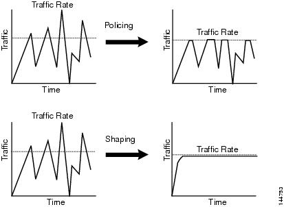
For information about defining policing and shaping parameters in a QoS policy, see Defining QoS Class Policing Parameters and Defining QoS Class Shaping Parameters.
Related Topics
•![]() Understanding the Token-Bucket Mechanism
Understanding the Token-Bucket Mechanism
•![]() Understanding Marking Parameters
Understanding Marking Parameters
•![]() Understanding Queuing Parameters
Understanding Queuing Parameters
•![]() Quality of Service on Cisco IOS Routers
Quality of Service on Cisco IOS Routers
Understanding the Token-Bucket Mechanism
Both policing and shaping use a token-bucket mechanism to regulate data flow. A token bucket is a formal definition of a rate of transfer. It has three components: a burst size, a mean rate, and a time interval (Tc). Any two values may be derived from the third using this formula:
mean rate = burst size / time interval
These terms are defined as follows:
•![]() Mean rate—Also called the committed information rate (CIR), it specifies how much data can be sent or forwarded per unit time on average. The CIR is defined either as an absolute value or as a percentage of the available bandwidth on the interface. When defined as a percentage, the equivalent value in bits per second (bps) is calculated after deployment based on the interface bandwidth and the percent value defined in the policy.
Mean rate—Also called the committed information rate (CIR), it specifies how much data can be sent or forwarded per unit time on average. The CIR is defined either as an absolute value or as a percentage of the available bandwidth on the interface. When defined as a percentage, the equivalent value in bits per second (bps) is calculated after deployment based on the interface bandwidth and the percent value defined in the policy.
Note ![]() If the interface bandwidth changes (for example, more bandwidth is added), the bps value of the CIR is recalculated based on the revised amount of bandwidth.
If the interface bandwidth changes (for example, more bandwidth is added), the bps value of the CIR is recalculated based on the revised amount of bandwidth.
•![]() Burst size—Also called the committed burst (Bc) size, it specifies for each burst how much data can be sent within a given time without creating scheduling concerns. When you use percentages to calculate the CIR, burst size is measured in milliseconds.
Burst size—Also called the committed burst (Bc) size, it specifies for each burst how much data can be sent within a given time without creating scheduling concerns. When you use percentages to calculate the CIR, burst size is measured in milliseconds.
•![]() Time interval—Also called the measurement interval, it specifies the amount of time in seconds per burst. Over any integral multiple of this interval, the bit rate of the interface does not exceed the mean rate. The bit rate, however, might be arbitrarily fast within the interval.
Time interval—Also called the measurement interval, it specifies the amount of time in seconds per burst. Over any integral multiple of this interval, the bit rate of the interface does not exceed the mean rate. The bit rate, however, might be arbitrarily fast within the interval.
In the token-bucket metaphor, tokens are put into the bucket at a certain rate. These tokens represent permission for the source to send a certain number of bits into the network. To send a packet, the regulator (policer or shaper) must remove a number of tokens from the bucket that equals the packet size.
Security Manager uses a two-bucket algorithm, as shown in Figure 13-12. The first bucket is the conform bucket and the second bucket is the exceed bucket. The full size of the conform bucket is the number of bytes specified as the normal burst size. The full size of the exceed bucket is the number of bytes specified in the maximum burst size. Both buckets are initially full, and they are updated based on the token arrival rate, which is determined by the CIR. If the number of bytes in the arriving packet is less than the number of bytes in the conform bucket, the packet conforms. The required number of tokens are removed from the conform bucket and the defined conform action is taken (for example, the packet is transmitted). The exceed bucket is unaffected.
If the conform bucket does not contain sufficient tokens, the excess token bucket is checked against the number of bytes in the packet. If enough tokens are present in the two buckets combined, the exceed action is taken on the packet and the required number of bytes are removed from each bucket. If the exceed bucket contains an insufficient number of bytes, the packet is in violation of the burst limits and the violate action is taken on the packet.
Figure 13-12 Two-Token Bucket Algorithm
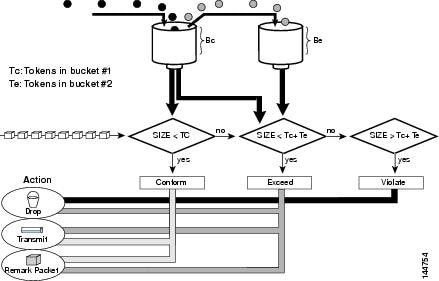
When you use traffic policing, the token-bucket algorithm provides three actions for each packet: a conform action, an exceed action, and an optional violate action. For instance, packets that conform can be configured to be transmitted, packets that exceed can be configured to be sent with a decreased priority, and packets that violate can be configured to be dropped.
Traffic policing is often configured on interfaces at the edge of a network to limit the rate of traffic entering or leaving the network. In the most common traffic policing configurations, traffic that conforms is transmitted and traffic that exceeds is sent with a decreased priority or is dropped. You can change these configuration options to suit your network needs.
When you use traffic shaping, the token-bucket mechanism includes a data buffer for holding packets that cannot be sent immediately. (Policers do not have such a buffer.) The token buckets permit packets to be sent in bursts, but places bounds on this capability so that the flow is never faster than the capacity of the buckets plus the time interval multiplied by the refill rate. The buffer also guarantees that the long-term transmission rate does not exceed the CIR.
Related Topics
•![]() Understanding Control Plane Policing
Understanding Control Plane Policing
•![]() Understanding Policing and Shaping Parameters
Understanding Policing and Shaping Parameters
Understanding Control Plane Policing
The Control Plane Policing feature enables you to manage input traffic entering the control plane (CP) of the router. The CP is a collection of processes that run at the process level on the route processor. These processes collectively provide high-level control for most Cisco IOS functions. Control plane policing protects the CP of Cisco IOS routers and switches against reconnaissance and denial-of-service (DoS) attacks, enabling the CP to maintain packet forwarding and protocol states despite an attack or heavy traffic load on the router or switch.
The Control Plane Policing feature treats the CP as a separate entity with its own ingress (input) and egress (output) ports, enabling you to use Security Manager to configure QoS policies on input. These policies are applied when a packet enters the CP. You can configure a QoS policy to prevent unwanted packets from progressing after a specified rate limit is reached. For example, a system administrator can limit all TCP/SYN packets that are destined for the CP to a maximum rate of 1 megabit per second. Additional packets beyond this limit are silently discarded.
The following types of Layer 3 packets are forwarded to the CP and processed by aggregate control plane policing:
•![]() Routing protocol control packets
Routing protocol control packets
•![]() Packets destined for the local IP address of the router
Packets destined for the local IP address of the router
•![]() Packets from management protocols, such as SNMP, Telnet, and secure shell (SSH).
Packets from management protocols, such as SNMP, Telnet, and secure shell (SSH).
Note ![]() Support for output policing is available only in Cisco IOS Release 12.3(4)T and later T-train releases.
Support for output policing is available only in Cisco IOS Release 12.3(4)T and later T-train releases.
For information about how to define Control Plane Policing, see Defining QoS on the Control Plane. For more information about this feature, refer to the document, Control Plane Policing on Cisco.com at this URL:
http://www.cisco.com/en/US/docs/ios/qos/configuration/guide/ctrl_plane_policng.html
Related Topics
•![]() Understanding the Token-Bucket Mechanism
Understanding the Token-Bucket Mechanism
•![]() Understanding Policing and Shaping Parameters
Understanding Policing and Shaping Parameters
Defining QoS Policies
When you define QoS policies, you must first decide whether to configure the policy on specific interfaces or on the control plane. This initial choice determines how you configure the rest of the policy, as described in the following topics:
•![]() Defining QoS on the Control Plane
Defining QoS on the Control Plane
Note ![]() If you define a QoS policy on both the interfaces and the control plane of the same device, only the control plane configuration is deployed.
If you define a QoS policy on both the interfaces and the control plane of the same device, only the control plane configuration is deployed.
Related Topics
•![]() Quality of Service on Cisco IOS Routers
Quality of Service on Cisco IOS Routers
Defining QoS on Interfaces
You can create multiple QoS interface definitions, each of which applies to either input traffic (entering the router) or output traffic (exiting the router).
When you create a QoS interface definition on output traffic, you have the option of configuring hierarchical shaping on the interface as a whole instead of configuring shaping on individual QoS classes.
After you create your interface definitions, you must define one or more QoS classes on each interface. QoS classes contain the matching criteria that determine which packets are included in the class and the QoS functions (marking, queuing, policing, and shaping) to apply to that traffic. You can configure each interface (or interface role) with up to 16 QoS classes, each containing its own set of matching criteria and a defined set of QoS functions to apply to the traffic in that class.
For each interface, we recommend that for each interface you define at least one QoS class and a default class. If you do not configure a default class, packets that do not match the criteria of the other defined classes are treated as members of a default class that has no configured QoS functionality. Packets assigned to this class are placed in a simple first-in first-out (FIFO) queue, and are forwarded at a rate determined by the available underlying link bandwidth. This FIFO queue is managed by tail drop, which avoids congestion by dropping packets from the queue until it is no longer full.
Note ![]() QoS is applied to packets on a first-match basis. The router examines the table of QoS classes starting from the top and applies the properties of the first class whose matching criteria matches the packet. Therefore, it is important that you define and order your classes carefully. The default class should be placed last to prevent traffic that matches a specific class from being treated as unmatched traffic.
QoS is applied to packets on a first-match basis. The router examines the table of QoS classes starting from the top and applies the properties of the first class whose matching criteria matches the packet. Therefore, it is important that you define and order your classes carefully. The default class should be placed last to prevent traffic that matches a specific class from being treated as unmatched traffic.
Before You Begin
Ensure that Cisco Express Forwarding (CEF) is enabled on the router. For more information, see CEF Interface Settings on Cisco IOS Routers.
Related Topics
•![]() Defining QoS on the Control Plane
Defining QoS on the Control Plane
•![]() Quality of Service on Cisco IOS Routers
Quality of Service on Cisco IOS Routers
Step 1 ![]() Do one of the following:
Do one of the following:
•![]() (Device view) Select Platform > Quality of Service from the Policy selector.
(Device view) Select Platform > Quality of Service from the Policy selector.
•![]() (Policy view) Select Router Platform > Quality of Service from the Policy Type selector. Select an existing policy or create a new one.
(Policy view) Select Router Platform > Quality of Service from the Policy Type selector. Select an existing policy or create a new one.
The Quality of Service page is displayed. See Table J-89 on page J-148 for a description of the fields on this page.
Step 2 ![]() In the Applied to field, select Interfaces to define QoS parameters for specific interfaces on the selected router.
In the Applied to field, select Interfaces to define QoS parameters for specific interfaces on the selected router.
Step 3 ![]() Click the Add button under the upper table to display the QoS Policy dialog box. See Table J-90 on page J-149 for a description of the fields in this dialog box.
Click the Add button under the upper table to display the QoS Policy dialog box. See Table J-90 on page J-149 for a description of the fields in this dialog box.
Step 4 ![]() In the Interface field, enter the name of an interface or interface role, or click Select to display a selector.
In the Interface field, enter the name of an interface or interface role, or click Select to display a selector.
Tip ![]() If the interface role you want is not listed in the selector, click the Create button or the Edit button to open the Interface Role Dialog Box, page F-56. From here you can define an interface role to use in the policy.
If the interface role you want is not listed in the selector, click the Create button or the Edit button to open the Interface Role Dialog Box, page F-56. From here you can define an interface role to use in the policy.
Step 5 ![]() Select the traffic direction on which you want to apply the QoS definition, Output (traffic exiting the interface) or Input (traffic entering the interface). Queuing and shaping can be applied only to output traffic.
Select the traffic direction on which you want to apply the QoS definition, Output (traffic exiting the interface) or Input (traffic entering the interface). Queuing and shaping can be applied only to output traffic.
Step 6 ![]() (Optional) Define interface-level (hierarchical) shaping parameters. See Table J-90 on page J-149 for details.
(Optional) Define interface-level (hierarchical) shaping parameters. See Table J-90 on page J-149 for details.
Note ![]() When you enable hierarchical shaping on an interface, you cannot define shaping parameters for specific QoS classes. Shaping can be used only on output traffic. See Understanding Policing and Shaping Parameters for more information about shaping.
When you enable hierarchical shaping on an interface, you cannot define shaping parameters for specific QoS classes. Shaping can be used only on output traffic. See Understanding Policing and Shaping Parameters for more information about shaping.
Step 7 ![]() Click OK. The QoS interface definition is displayed in the upper table of the Quality of Service page.
Click OK. The QoS interface definition is displayed in the upper table of the Quality of Service page.
Note ![]() To edit a QoS interface definition, select an interface from the upper table, then click the Edit button. To remove an interface definition, select it from the table, then click the Delete button. You cannot delete an interface that has defined classes.
To edit a QoS interface definition, select an interface from the upper table, then click the Edit button. To remove an interface definition, select it from the table, then click the Delete button. You cannot delete an interface that has defined classes.
Step 8 ![]() With the interface selected in the upper table, click the Add button beneath the QoS Classes table. The QoS Class dialog box is displayed. See Table J-91 on page J-151 for a description of the fields in this dialog box.
With the interface selected in the upper table, click the Add button beneath the QoS Classes table. The QoS Class dialog box is displayed. See Table J-91 on page J-151 for a description of the fields in this dialog box.
The QoS Class dialog box enables you to determine which traffic over the selected interface is included in the QoS class and how to handle that traffic.
Step 9 ![]() (Optional) Select the Default class check box if you are defining the properties of the default QoS class for this interface. The default class is assigned to all traffic that does not match the criteria of the other defined classes.
(Optional) Select the Default class check box if you are defining the properties of the default QoS class for this interface. The default class is assigned to all traffic that does not match the criteria of the other defined classes.
Step 10 ![]() Define the QoS class using one or more tabs in the QoS Class dialog box, as described in:
Define the QoS class using one or more tabs in the QoS Class dialog box, as described in:
•![]() Defining QoS Class Matching Parameters
Defining QoS Class Matching Parameters
•![]() Defining QoS Class Marking Parameters
Defining QoS Class Marking Parameters
•![]() Defining QoS Class Queuing Parameters
Defining QoS Class Queuing Parameters
•![]() Defining QoS Class Policing Parameters
Defining QoS Class Policing Parameters
•![]() Defining QoS Class Shaping Parameters
Defining QoS Class Shaping Parameters
Step 11 ![]() Repeat Step 8 through Step 10 to add QoS classes to the interface defined in Step 3. If required, use the Up Row and Down Row buttons to reorder the classes.
Repeat Step 8 through Step 10 to add QoS classes to the interface defined in Step 3. If required, use the Up Row and Down Row buttons to reorder the classes.
Note ![]() To edit a QoS class, select the relevant interface from the upper table to display its defined classes in the QoS Class table. Select the class to edit, then click the Edit button. To remove a class, select it from the table, then click the Delete button.
To edit a QoS class, select the relevant interface from the upper table to display its defined classes in the QoS Class table. Select the class to edit, then click the Edit button. To remove a class, select it from the table, then click the Delete button.
Step 12 ![]() Repeat Step 3 through Step 11 to define QoS classes for a different interface on the selected router.
Repeat Step 3 through Step 11 to define QoS classes for a different interface on the selected router.
Defining QoS on the Control Plane
When you configure QoS on input traffic entering the control plane, you can define multiple QoS classes, including a default class for traffic that does not match the criteria you define for the other classes. After defining the matching criteria for a particular class, you can configure a policing definition for that class. (Marking, queuing, and shaping are not available.) For more information, see Understanding Control Plane Policing.
QoS policies defined on the control plane override any QoS parameters defined on an interface of the same device.
Note ![]() QoS is applied to packets on a first-match basis. The router examines the table of QoS classes starting from the top and applies the properties of the first class whose matching criteria matches the packet. Therefore, it is important that you define and order your classes carefully. The default class should be placed last to prevent traffic that matches a specific class from being treated as unmatched traffic.
QoS is applied to packets on a first-match basis. The router examines the table of QoS classes starting from the top and applies the properties of the first class whose matching criteria matches the packet. Therefore, it is important that you define and order your classes carefully. The default class should be placed last to prevent traffic that matches a specific class from being treated as unmatched traffic.
Before You Begin
Ensure that Cisco Express Forwarding (CEF) is enabled on the router. For more information, see CEF Interface Settings on Cisco IOS Routers.
Related Topics
•![]() Quality of Service on Cisco IOS Routers
Quality of Service on Cisco IOS Routers
Step 1 ![]() Do one of the following:
Do one of the following:
•![]() (Device view) Select Platform > Quality of Service from the Policy selector.
(Device view) Select Platform > Quality of Service from the Policy selector.
•![]() (Policy view) Select Router Platform > Quality of Service from the Policy Type selector. Select an existing policy or create a new one.
(Policy view) Select Router Platform > Quality of Service from the Policy Type selector. Select an existing policy or create a new one.
The Quality of Service page is displayed. See Table J-89 on page J-148 for a description of the fields on this page.
Step 2 ![]() In the Applied to field, select Control Plane to define QoS policing on input traffic entering the control plane.
In the Applied to field, select Control Plane to define QoS policing on input traffic entering the control plane.
Step 3 ![]() Click the Add button beneath the Control Plane QoS Classes table. The QoS Class dialog box is displayed. See Table J-91 on page J-151 for a description of the fields in this dialog box.
Click the Add button beneath the Control Plane QoS Classes table. The QoS Class dialog box is displayed. See Table J-91 on page J-151 for a description of the fields in this dialog box.
The QoS Class dialog box enables you to determine which traffic over the selected interface is included in the QoS class and how to handle that traffic.
Step 4 ![]() (Optional) Select the Default class check box if you are defining the properties of the default QoS class for the control plane. The default class is assigned to all traffic that does not match the criteria of the other defined classes.
(Optional) Select the Default class check box if you are defining the properties of the default QoS class for the control plane. The default class is assigned to all traffic that does not match the criteria of the other defined classes.
Step 5 ![]() Define the QoS class using the tabs in the QoS Class dialog box, as described in the following sections:
Define the QoS class using the tabs in the QoS Class dialog box, as described in the following sections:
•![]() Defining QoS Class Matching Parameters
Defining QoS Class Matching Parameters
•![]() Defining QoS Class Policing Parameters
Defining QoS Class Policing Parameters
Step 6 ![]() Repeat Step 3 through Step 5 to add QoS classes to the control plane. If required, use the Up Row and Down Row buttons to reorder the classes.
Repeat Step 3 through Step 5 to add QoS classes to the control plane. If required, use the Up Row and Down Row buttons to reorder the classes.
Defining QoS Class Matching Parameters
When you define matching parameters, you must define matching criteria and specify whether packets must meet one or all of the criteria to be considered part of the class. See Understanding Matching Parameters for more information.
Note ![]() You do not define matching parameters when configuring the default class.
You do not define matching parameters when configuring the default class.
Related Topics
•![]() Defining QoS Class Marking Parameters
Defining QoS Class Marking Parameters
•![]() Defining QoS Class Queuing Parameters
Defining QoS Class Queuing Parameters
•![]() Defining QoS Class Policing Parameters
Defining QoS Class Policing Parameters
•![]() Defining QoS Class Shaping Parameters
Defining QoS Class Shaping Parameters
•![]() Quality of Service on Cisco IOS Routers
Quality of Service on Cisco IOS Routers
Step 1 ![]() On the Quality of Service page, click the Add button beneath the QoS Classes table, or select a class and then click the Edit button. The QoS Class dialog box is displayed.
On the Quality of Service page, click the Add button beneath the QoS Classes table, or select a class and then click the Edit button. The QoS Class dialog box is displayed.
Step 2 ![]() Click the Matching tab. See Table J-92 on page J-153 for a description of the fields on this tab.
Click the Matching tab. See Table J-92 on page J-153 for a description of the fields on this tab.
Step 3 ![]() Select a matching method:
Select a matching method:
•![]() Any—Traffic matching any of the defined parameters is included in this class.
Any—Traffic matching any of the defined parameters is included in this class.
•![]() All—Only traffic matching all of the defined parameters is included in this class.
All—Only traffic matching all of the defined parameters is included in this class.
Step 4 ![]() (Optional) Under Protocol, click Add to display a selector for choosing the protocols to include in this class. Select one or more items from the Available Protocols list, then click >> to add them to the Selected Protocols list.
(Optional) Under Protocol, click Add to display a selector for choosing the protocols to include in this class. Select one or more items from the Available Protocols list, then click >> to add them to the Selected Protocols list.
Note ![]() When configuring QoS on the control plane, only the ARP protocol can be selected.
When configuring QoS on the control plane, only the ARP protocol can be selected.
When you finish, click OK to save your definitions and return to the QoS Class dialog box. Your selections are displayed in the Protocol field.
Step 5 ![]() (Optional) Under Precedence, click Add to display a selector for choosing which IP precedence values (from 0 to 7) to include in this class. Select one or more items from the Available Precedences list, then click >> to add them to the Selected Precedences list. Traffic that arrives marked with one of these values matches this criterion.
(Optional) Under Precedence, click Add to display a selector for choosing which IP precedence values (from 0 to 7) to include in this class. Select one or more items from the Available Precedences list, then click >> to add them to the Selected Precedences list. Traffic that arrives marked with one of these values matches this criterion.
Note ![]() For more information about IP precedence values, see Table 13-6.
For more information about IP precedence values, see Table 13-6.
When you finish, click OK to save your definitions and return to the QoS Class dialog box. Your selections are displayed in the Precedences field.
Step 6 ![]() (Optional) Under DSCP, click Add to display a selector for choosing which DSCP values (from 0 to 63) to include in this class. Select one or more items (up to eight) from the Available DSCPs list, then click >> to add them to the Selected DSCPs list. Traffic that arrives marked with one of these values matches this criterion.
(Optional) Under DSCP, click Add to display a selector for choosing which DSCP values (from 0 to 63) to include in this class. Select one or more items (up to eight) from the Available DSCPs list, then click >> to add them to the Selected DSCPs list. Traffic that arrives marked with one of these values matches this criterion.
When you finish, click OK to save your definitions and return to the QoS Class dialog box. Your selections are displayed in the DSCP field.
Step 7 ![]() (Optional) Under ACL, define ACLs as part of the matching criteria for this class:
(Optional) Under ACL, define ACLs as part of the matching criteria for this class:
a. ![]() Click Edit to display the Edit ACLs dialog box. Use this dialog box to define which ACLs to include in this class. See Table J-93 on page J-154 for a description of the fields in this dialog box.
Click Edit to display the Edit ACLs dialog box. Use this dialog box to define which ACLs to include in this class. See Table J-93 on page J-154 for a description of the fields in this dialog box.
b. ![]() Enter one or more ACLs, or click Select to display a selector (see Object Selectors, page F-205). Traffic that matches these ACL definitions matches this criterion.
Enter one or more ACLs, or click Select to display a selector (see Object Selectors, page F-205). Traffic that matches these ACL definitions matches this criterion.
c. ![]() When you finish, click OK twice to save your definitions and return to the QoS Class dialog box. Your selections are displayed in the ACL field.
When you finish, click OK twice to save your definitions and return to the QoS Class dialog box. Your selections are displayed in the ACL field.
Tip ![]() Use the up and down arrows to order the ACLs. We recommend placing more frequently used ACLs at the top of the list to optimize the matching process.
Use the up and down arrows to order the ACLs. We recommend placing more frequently used ACLs at the top of the list to optimize the matching process.
Step 8 ![]() Go to another tab or click OK to save your definitions locally on the client and close the dialog box. The defined class is displayed in the QoS Classes table on the Quality of Service page.
Go to another tab or click OK to save your definitions locally on the client and close the dialog box. The defined class is displayed in the QoS Classes table on the Quality of Service page.
Step 9 ![]() Do one of the following:
Do one of the following:
•![]() When defining QoS on interfaces, continue as described in Defining QoS on Interfaces.
When defining QoS on interfaces, continue as described in Defining QoS on Interfaces.
•![]() When defining control plane policing, continue as described in Defining QoS on the Control Plane.
When defining control plane policing, continue as described in Defining QoS on the Control Plane.
Defining QoS Class Marking Parameters
When you define marking parameters, you can mark the packets in this QoS class with either a precedence value or a DSCP value. See Understanding Marking Parameters for more information.
Note ![]() Marking is not available when you configure QoS on the control plane.
Marking is not available when you configure QoS on the control plane.
Related Topics
•![]() Defining QoS Class Matching Parameters
Defining QoS Class Matching Parameters
•![]() Defining QoS Class Queuing Parameters
Defining QoS Class Queuing Parameters
•![]() Defining QoS Class Policing Parameters
Defining QoS Class Policing Parameters
•![]() Defining QoS Class Shaping Parameters
Defining QoS Class Shaping Parameters
•![]() Quality of Service on Cisco IOS Routers
Quality of Service on Cisco IOS Routers
Step 1 ![]() On the Quality of Service page, click the Add button beneath the QoS Classes table, or select a class and then click the Edit button. The QoS Class dialog box is displayed.
On the Quality of Service page, click the Add button beneath the QoS Classes table, or select a class and then click the Edit button. The QoS Class dialog box is displayed.
Step 2 ![]() Click the Marking tab. See Table J-94 on page J-155 for a description of the fields on this tab.
Click the Marking tab. See Table J-94 on page J-155 for a description of the fields on this tab.
Step 3 ![]() Select the Enable Marking check box.
Select the Enable Marking check box.
Step 4 ![]() Select one of the following marking options:
Select one of the following marking options:
•![]() Precedence—Select an IP precedence value (0 to 7) from the displayed list. For more information about these values, see Table 13-6.
Precedence—Select an IP precedence value (0 to 7) from the displayed list. For more information about these values, see Table 13-6.
•![]() DSCP—Select a DSCP value (0 to 63) from the displayed list.
DSCP—Select a DSCP value (0 to 63) from the displayed list.
Step 5 ![]() Go to another tab or click OK to save your definitions locally on the client and close the dialog box. The defined class is displayed in the QoS Classes table on the Quality of Service page.
Go to another tab or click OK to save your definitions locally on the client and close the dialog box. The defined class is displayed in the QoS Classes table on the Quality of Service page.
Step 6 ![]() Continue as described in Defining QoS Policies.
Continue as described in Defining QoS Policies.
Defining QoS Class Queuing Parameters
When you define queuing parameters, you can specify the amount of available bandwidth to provide to the traffic in this QoS class. You can also define a fixed amount of bandwidth that must be provided to high-priority traffic; you can define the priority parameter on only one class per interface. In addition, you must specify the type of queue management to perform on this class. See Understanding Queuing Parameters for more information.
Note ![]() Queuing is not available when you configure QoS on the control plane.
Queuing is not available when you configure QoS on the control plane.
Related Topics
•![]() Defining QoS Class Matching Parameters
Defining QoS Class Matching Parameters
•![]() Defining QoS Class Marking Parameters
Defining QoS Class Marking Parameters
•![]() Defining QoS Class Policing Parameters
Defining QoS Class Policing Parameters
•![]() Defining QoS Class Shaping Parameters
Defining QoS Class Shaping Parameters
•![]() Quality of Service on Cisco IOS Routers
Quality of Service on Cisco IOS Routers
Step 1 ![]() On the Quality of Service page, click the Add button beneath the QoS Classes table, or select a class and then click the Edit button. The QoS Class dialog box is displayed.
On the Quality of Service page, click the Add button beneath the QoS Classes table, or select a class and then click the Edit button. The QoS Class dialog box is displayed.
Step 2 ![]() Click the Queuing and Congestion Avoidance tab. See Table J-95 on page J-156 for a description of the fields on this tab.
Click the Queuing and Congestion Avoidance tab. See Table J-95 on page J-156 for a description of the fields on this tab.
Step 3 ![]() Click the Enable Queuing and Congestion Avoidance check box.
Click the Enable Queuing and Congestion Avoidance check box.
Queuing options depend on whether you are defining the default class or a different class:
•![]() When you define any class other than the default class, select one of the following queuing options:
When you define any class other than the default class, select one of the following queuing options:
–![]() Priority—Define the amount of bandwidth to make available to high-priority traffic. Low-Latency Queuing (LLQ) ensures that this traffic receives this fixed amount of bandwidth at all times. This is particularly useful for voice traffic, which requires low latency. You can define this amount by percentage or by an absolute value of kilobits per second.
Priority—Define the amount of bandwidth to make available to high-priority traffic. Low-Latency Queuing (LLQ) ensures that this traffic receives this fixed amount of bandwidth at all times. This is particularly useful for voice traffic, which requires low latency. You can define this amount by percentage or by an absolute value of kilobits per second.
Note ![]() You can define this option for only one class per interface.
You can define this option for only one class per interface.
–![]() Bandwidth—Enter the amount of bandwidth to allocate to this class. You can define this amount by percentage or by an absolute value of kilobits per second.
Bandwidth—Enter the amount of bandwidth to allocate to this class. You can define this amount by percentage or by an absolute value of kilobits per second.
Note ![]() The sum of all class bandwidth allocations on an interface cannot exceed 100 percent of the total available bandwidth.
The sum of all class bandwidth allocations on an interface cannot exceed 100 percent of the total available bandwidth.
•![]() When you define the default class, select one of the following queuing options:
When you define the default class, select one of the following queuing options:
–![]() Fair queue—Enter the number of queues to reserve for the default class. Values range in powers of 2 from 16 to 4096. By default, the number of queues is based on the available bandwidth of the selected interface. For more information, seeTable 13-7.
Fair queue—Enter the number of queues to reserve for the default class. Values range in powers of 2 from 16 to 4096. By default, the number of queues is based on the available bandwidth of the selected interface. For more information, seeTable 13-7.
–![]() Bandwidth—Enter the amount of bandwidth to allocate to this class. You can define this amount by percentage or by an absolute value of kilobits per second.
Bandwidth—Enter the amount of bandwidth to allocate to this class. You can define this amount by percentage or by an absolute value of kilobits per second.
Step 4 ![]() (Optional) Define one of the following queue length management options:
(Optional) Define one of the following queue length management options:
•![]() Queue Limit—(Default) Specify the maximum number of packets allowed. If you select this option, tail drop drops excess packets when the queue reaches its capacity.
Queue Limit—(Default) Specify the maximum number of packets allowed. If you select this option, tail drop drops excess packets when the queue reaches its capacity.
•![]() WRED Weight for Mean Queue Depth—WRED proactively drops packets until the transmitting protocol (usually TCP) responds by dropping its transmission rate, thereby alleviating congestion. Configure WRED by entering an exponential weight factor that is used to calculate the average queue size.
WRED Weight for Mean Queue Depth—WRED proactively drops packets until the transmitting protocol (usually TCP) responds by dropping its transmission rate, thereby alleviating congestion. Configure WRED by entering an exponential weight factor that is used to calculate the average queue size.
For more information, see Tail Drop vs. WRED.
Note ![]() You should change the default only if you are certain that your applications will benefit from a different value.
You should change the default only if you are certain that your applications will benefit from a different value.
Note ![]() Do not use WRED with protocols that are not sufficiently robust to reduce their transmission rates in response to packet loss, such as IPX or AppleTalk. WRED cannot be configured when you select the Priority percent option.
Do not use WRED with protocols that are not sufficiently robust to reduce their transmission rates in response to packet loss, such as IPX or AppleTalk. WRED cannot be configured when you select the Priority percent option.
Step 5 ![]() Go to another tab or click OK to save your definitions locally on the client and close the dialog box. The defined class is displayed in the QoS Classes table on the Quality of Service page.
Go to another tab or click OK to save your definitions locally on the client and close the dialog box. The defined class is displayed in the QoS Classes table on the Quality of Service page.
Step 6 ![]() Continue as described in Defining QoS Policies.
Continue as described in Defining QoS Policies.
Defining QoS Class Policing Parameters
When you define policing parameters, you must specify the average data rate, which determines the amount of traffic that can be transmitted. In addition, you must specify the action to take on traffic bursts that exceed this data rate.
You can configure policing for all QoS classes, including the default class. For more information about policing, see Understanding Policing and Shaping Parameters.
You can also configure policing on the control plane. For more information, see Understanding Control Plane Policing.
Related Topics
•![]() Defining QoS Class Matching Parameters
Defining QoS Class Matching Parameters
•![]() Defining QoS Class Marking Parameters
Defining QoS Class Marking Parameters
•![]() Defining QoS Class Queuing Parameters
Defining QoS Class Queuing Parameters
•![]() Defining QoS Class Shaping Parameters
Defining QoS Class Shaping Parameters
•![]() Quality of Service on Cisco IOS Routers
Quality of Service on Cisco IOS Routers
Step 1 ![]() On the Quality of Service page, click the Add button beneath the QoS Classes table, or select a class and then click the Edit button. The QoS Class dialog box is displayed.
On the Quality of Service page, click the Add button beneath the QoS Classes table, or select a class and then click the Edit button. The QoS Class dialog box is displayed.
Step 2 ![]() Click the Policing tab. See Table J-96 on page J-157 for a description of the fields on this tab.
Click the Policing tab. See Table J-96 on page J-157 for a description of the fields on this tab.
Step 3 ![]() Select the Enable Policing check box.
Select the Enable Policing check box.
Step 4 ![]() Define CIR, confirm burst, and excess burst values. You can define the CIR by percentage or by an absolute value of bits per second. The option you choose determines how you define the burst values.
Define CIR, confirm burst, and excess burst values. You can define the CIR by percentage or by an absolute value of bits per second. The option you choose determines how you define the burst values.
Step 5 ![]() Select the action to perform on packets that conform to the rate limit:
Select the action to perform on packets that conform to the rate limit:
•![]() transmit—Transmit the packet.
transmit—Transmit the packet.
•![]() set-prec-transmit—Set the IP precedence to a defined value, then send the packet. This option is not available when configuring QoS on the control plane.
set-prec-transmit—Set the IP precedence to a defined value, then send the packet. This option is not available when configuring QoS on the control plane.
•![]() set-dscp-transmit—Set the DSCP to a defined value, then send the packet. This option is not available when configuring QoS on the control plane.
set-dscp-transmit—Set the DSCP to a defined value, then send the packet. This option is not available when configuring QoS on the control plane.
•![]() drop—Drop the packet.
drop—Drop the packet.
Step 6 ![]() Select the action to perform on exceed packets. The list of available actions depends on the selected conform action.
Select the action to perform on exceed packets. The list of available actions depends on the selected conform action.
For example, if transmit is performed on conforming packets, you can select any of the actions listed in Step 5 for exceeding packets. However, if you selected one of the set actions for conforming packets, you can select only a set action or the drop action for exceeding packets. If you selected drop as the conform action, you must select drop as the exceed action.
Step 7 ![]() Select the action to perform on violate packets. The list of available actions depends on the selected exceed action.
Select the action to perform on violate packets. The list of available actions depends on the selected exceed action.
For example, if transmit is performed on exceeding packets, you can select any of the actions listed in Step 5 for violating packets. However, if you selected one of the set actions for exceeding packets, you can select only a set action or the drop action for violating packets. If you selected drop as the exceed action, you must select drop as the violate action.
Step 8 ![]() Go to another tab, or click OK to save your definitions locally on the client and close the dialog box. The defined class is displayed in the QoS Classes table on the Quality of Service page.
Go to another tab, or click OK to save your definitions locally on the client and close the dialog box. The defined class is displayed in the QoS Classes table on the Quality of Service page.
Step 9 ![]() Do one of the following:
Do one of the following:
•![]() When defining QoS on interfaces, continue as described in Defining QoS Policies.
When defining QoS on interfaces, continue as described in Defining QoS Policies.
•![]() When defining control plane policing, continue as described in Defining QoS on the Control Plane.
When defining control plane policing, continue as described in Defining QoS on the Control Plane.
Defining QoS Class Shaping Parameters
When you define shaping parameters, you must specify whether to base traffic shaping on the average data rate or on the average data rate plus the excess burst rate that occurs during traffic peaks. In both cases, traffic that exceeds these definitions is buffered until the rate lowers, allowing the packets to be sent.
The following conditions pertain:
•![]() Shaping can be used only on output traffic.
Shaping can be used only on output traffic.
•![]() Shaping can be configured for all QoS classes, including the default class.
Shaping can be configured for all QoS classes, including the default class.
•![]() Shaping is not available when you configure the QoS class for priority traffic.
Shaping is not available when you configure the QoS class for priority traffic.
•![]() Shaping is not available when you configure QoS on the control plane.
Shaping is not available when you configure QoS on the control plane.
For more information about shaping, see Understanding Policing and Shaping Parameters.
Tip ![]() To configure shaping on all the QoS classes defined for the interface (hierarchical shaping), see Defining QoS on Interfaces.
To configure shaping on all the QoS classes defined for the interface (hierarchical shaping), see Defining QoS on Interfaces.
Related Topics
•![]() Defining QoS Class Matching Parameters
Defining QoS Class Matching Parameters
•![]() Defining QoS Class Marking Parameters
Defining QoS Class Marking Parameters
•![]() Defining QoS Class Queuing Parameters
Defining QoS Class Queuing Parameters
•![]() Defining QoS Class Policing Parameters
Defining QoS Class Policing Parameters
•![]() Quality of Service on Cisco IOS Routers
Quality of Service on Cisco IOS Routers
Step 1 ![]() On the Quality of Service page, click the Add button beneath the QoS Classes table, or select a class and then click the Edit button. The QoS Class dialog box is displayed.
On the Quality of Service page, click the Add button beneath the QoS Classes table, or select a class and then click the Edit button. The QoS Class dialog box is displayed.
Step 2 ![]() Click the Shaping tab. See Table J-97 on page J-159 for a description of the fields on this tab.
Click the Shaping tab. See Table J-97 on page J-159 for a description of the fields on this tab.
Step 3 ![]() Select the Enable Shaping check box.
Select the Enable Shaping check box.
Step 4 ![]() Select the shaping type (Average or Peak).
Select the shaping type (Average or Peak).
Step 5 ![]() Define CIR, sustained burst, and excess burst values. You can define the CIR by percentage or by an absolute value of bits per second. The option you choose determines how you define the burst values.
Define CIR, sustained burst, and excess burst values. You can define the CIR by percentage or by an absolute value of bits per second. The option you choose determines how you define the burst values.
Step 6 ![]() Proceed to another tab or click OK to save your definitions locally on the client and close the dialog box. The defined class is displayed in the QoS Classes table on the Quality of Service page.
Proceed to another tab or click OK to save your definitions locally on the client and close the dialog box. The defined class is displayed in the QoS Classes table on the Quality of Service page.
Step 7 ![]() Continue as described in Defining QoS Policies.
Continue as described in Defining QoS Policies.
BGP Routing on Cisco IOS Routers
BGP is an Exterior Gateway Protocol (EGP) that guarantees the loop-free exchange of routing information between autonomous systems (ASs). The primary function of a BGP system is to exchange information with other BGP systems about the networks it can reach, including AS path information. This information can be used to construct a graph of AS connectivity from which routing loops can be pruned and with which AS-level policy decisions can be enforced.
BGP is the routing protocol used on the Internet and is commonly used between Internet service providers. To achieve scalability at this level, BGP uses several route parameters (attributes) to define routing policies and maintain a stable routing environment. Additionally, BGP uses classless interdomain routing (CIDR) to greatly reduce the size of Internet routing tables.
A BGP route consists of a network number, a list of ASs through which information has passed (called the autonomous system path), and the defined path attributes.
A BGP router exchanges routing information only with those routers that you define as its neighbors. BGP neighbors exchange complete routing information when the TCP connection between them is established. Updates are sent to neighbors only when changes to the routing table are detected. BGP routers do not send regular, periodic updates.
The following topics describe the tasks you perform to create a BGP routing policy:
•![]() Redistributing Routes into BGP
Redistributing Routes into BGP
Note ![]() Security Manager supports versions 2, 3 and 4 of BGP, as defined in RFCs 1163, 1267 and 1771.
Security Manager supports versions 2, 3 and 4 of BGP, as defined in RFCs 1163, 1267 and 1771.
Related Topics
•![]() Static Routing on Cisco IOS Routers
Static Routing on Cisco IOS Routers
•![]() RIP Routing on Cisco IOS Routers
RIP Routing on Cisco IOS Routers
•![]() OSPF Routing on Cisco IOS Routers
OSPF Routing on Cisco IOS Routers
•![]() EIGRP Routing on Cisco IOS Routers
EIGRP Routing on Cisco IOS Routers
Defining BGP Routes
As with all EGPs, when you configure a BGP routing policy, you must define the relationship the router has with its neighbors. BGP supports two kinds of neighbors: internal (located in the same AS) and external (located in a different AS). Typically, external neighbors are adjacent to each other and share a subnet; internal neighbors can be anywhere in the same AS.
In addition, you can select whether to enable the following optional features:
•![]() Auto-summarization
Auto-summarization
•![]() Synchronization
Synchronization
•![]() Neighbor logging
Neighbor logging
If enabled, auto-summarization injects only the network route when a subnet is redistributed from an Interior Gateway Protocol (IGP) such as OSPF or EIGRP into BGP. Synchronization is useful if your AS acts as an intermediary, passing traffic from one AS to another AS, because it ensures that your AS is consistent about the routes it advertises. For example, if BGP were to advertise a route before all routers in your network had learned about the route through your IGP, your AS might receive traffic that some routers cannot yet route. Neighbor logging enables the router to keep track of messages issued by BGP neighbors when they reset, become unreachable, or restore their connection to the network.
This procedure describes how to define a BGP route. You can define only one BGP route on each router.
Related Topics
•![]() Redistributing Routes into BGP
Redistributing Routes into BGP
•![]() BGP Routing on Cisco IOS Routers
BGP Routing on Cisco IOS Routers
Step 1 ![]() Do one of the following:
Do one of the following:
•![]() (Device view) Select Platform > Routing > BGP from the Policy selector, then click the Setup tab in the work area.
(Device view) Select Platform > Routing > BGP from the Policy selector, then click the Setup tab in the work area.
•![]() (Policy view) Select Router Platform > Routing > BGP from the Policy Type selector. Select an existing policy or create a new one, and then click the Setup tab.
(Policy view) Select Router Platform > Routing > BGP from the Policy Type selector. Select an existing policy or create a new one, and then click the Setup tab.
The BGP Setup is displayed. See Table J-98 on page J-161 for a description of the fields on this tab.
Step 2 ![]() On the BGP Setup tab, enter the AS number to which the router belongs.
On the BGP Setup tab, enter the AS number to which the router belongs.
Step 3 ![]() (Optional) Enter the addresses of the networks that are local to this AS. You can use a combination of addresses and network/host objects, or click Select to display a selector (see Object Selectors, page F-205). For more information, see Specifying IP Addresses During Policy Definition, page 8-68.
(Optional) Enter the addresses of the networks that are local to this AS. You can use a combination of addresses and network/host objects, or click Select to display a selector (see Object Selectors, page F-205). For more information, see Specifying IP Addresses During Policy Definition, page 8-68.
Tip ![]() If the network you want is not listed, click the Create button or the Edit button in the selector to display the Add or Edit Network/Host Dialog Box, page F-141. From here you can define a network/host object to use in the policy.
If the network you want is not listed, click the Create button or the Edit button in the selector to display the Add or Edit Network/Host Dialog Box, page F-141. From here you can define a network/host object to use in the policy.
Step 4 ![]() Define external and internal BGP neighbors for the routers:
Define external and internal BGP neighbors for the routers:
a. ![]() Click Add under Neighbors to display the BGP Neighbors dialog box. See Table J-99 on page J-163 for a description of the fields in this dialog box.
Click Add under Neighbors to display the BGP Neighbors dialog box. See Table J-99 on page J-163 for a description of the fields in this dialog box.
b. ![]() Enter an AS number and then click Select to select the hosts that are neighbors within the defined AS. Internal neighbors are located in the same AS as the router; external neighbors are located in a different AS.
Enter an AS number and then click Select to select the hosts that are neighbors within the defined AS. Internal neighbors are located in the same AS as the router; external neighbors are located in a different AS.
c. ![]() Click OK to save your definitions and return to the BGP Neighbors dialog box.
Click OK to save your definitions and return to the BGP Neighbors dialog box.
d. ![]() (Optional) Repeat b. and c. to define neighbors in additional ASs.
(Optional) Repeat b. and c. to define neighbors in additional ASs.
Note ![]() When you define BGP neighbors, the IP addresses cannot belong to an interface on the selected router. In addition, you cannot define the same IP address in more than one AS.
When you define BGP neighbors, the IP addresses cannot belong to an interface on the selected router. In addition, you cannot define the same IP address in more than one AS.
When you finish, click OK in the BGP Neighbors dialog box to return to the BGP Setup tab. Your selections are displayed in the Neighbors field.
Step 5 ![]() (Optional) Select the Auto-Summary check box to enable automatic summarization. If automatic summarization is enabled, only the network route is injected into the BGP table when a subnet is redistributed from an IGP (such as OSPF or EIGRP) into BGP.
(Optional) Select the Auto-Summary check box to enable automatic summarization. If automatic summarization is enabled, only the network route is injected into the BGP table when a subnet is redistributed from an IGP (such as OSPF or EIGRP) into BGP.
Step 6 ![]() (Optional) Select the Synchronization check box to synchronize BGP with the IGP. Enabling this feature causes BGP to wait until the IGP propagates routing information across the AS.
(Optional) Select the Synchronization check box to synchronize BGP with the IGP. Enabling this feature causes BGP to wait until the IGP propagates routing information across the AS.
You do not need synchronization if your AS does not pass traffic it receives from one AS to another AS, or if all the routers in your AS run BGP. Disabling synchronization enables BGP to converge more quickly.
Step 7 ![]() (Optional) Select the Log-Neighbor check box to enable the logging of messages generated when a BGP neighbors resets, comes up, or goes down.
(Optional) Select the Log-Neighbor check box to enable the logging of messages generated when a BGP neighbors resets, comes up, or goes down.
Redistributing Routes into BGP
Redistribution refers to using a routing protocol, such as BGP, to advertise routes that are learned by some other means, such as a different routing protocol, static routes, or directly connected routes. For example, you can redistribute routes from the OSPF routing protocol into your BGP autonomous system (AS). Redistribution is necessary in networks that operate in multiple-protocol environments and can be applied to all IP-based routing protocols.
Before You Begin
•![]() Define a BGP AS. See Defining BGP Routes.
Define a BGP AS. See Defining BGP Routes.
Related Topics
•![]() BGP Routing on Cisco IOS Routers
BGP Routing on Cisco IOS Routers
Step 1 ![]() Do one of the following:
Do one of the following:
•![]() (Device view) Select Platform > Routing > BGP from the Policy selector, then click the Redistribution tab in the work area.
(Device view) Select Platform > Routing > BGP from the Policy selector, then click the Redistribution tab in the work area.
•![]() (Policy view) Select Router Platform > Routing > BGP from the Policy Type selector. Select an existing policy or create a new one, and then click the Redistribution tab.
(Policy view) Select Router Platform > Routing > BGP from the Policy Type selector. Select an existing policy or create a new one, and then click the Redistribution tab.
The BGP Redistribution tab is displayed. See Table J-100 on page J-163 for a description of the fields on this tab.
Step 2 ![]() On the BGP Redistribution tab, select a row from the BGP Redistribution Mappings table, then click Edit, or click Add to create a mapping. The BGP Redistribution Mapping dialog box appears. See Table J-101 on page J-165 for a description of the fields in this dialog box.
On the BGP Redistribution tab, select a row from the BGP Redistribution Mappings table, then click Edit, or click Add to create a mapping. The BGP Redistribution Mapping dialog box appears. See Table J-101 on page J-165 for a description of the fields in this dialog box.
Step 3 ![]() Select the protocol whose routes you want to redistribute into BGP.
Select the protocol whose routes you want to redistribute into BGP.
Note ![]() You can create a single mapping for each static route, RIP route, EIGRP AS, and OSPF process.
You can create a single mapping for each static route, RIP route, EIGRP AS, and OSPF process.
Step 4 ![]() (Optional) Modify the default metric (cost) of the redistributed routes. The metric determines the priority of the routes.
(Optional) Modify the default metric (cost) of the redistributed routes. The metric determines the priority of the routes.
Step 5 ![]() Click OK to save your definitions locally on the client and close the dialog box. The redistribution mapping appears in the Redistribution Mapping table in the BGP Redistribution tab.
Click OK to save your definitions locally on the client and close the dialog box. The redistribution mapping appears in the Redistribution Mapping table in the BGP Redistribution tab.
EIGRP Routing on Cisco IOS Routers
Enhanced Interior Gateway Routing Protocol (EIGRP) is an enhanced distance vector protocol developed by Cisco Systems that integrates the capabilities of link-state protocols. EIGRP is suited for many different topologies and media. Key capabilities that distinguish EIGRP from other routing protocols are fast convergence, support for variable-length subnet masks, partial updates, and multiple network-layer protocols.
The metric that the router uses to reach the destination, and to advertise to other routers, is the sum of the best-advertised metrics from all neighbors and the link cost to the best neighbor.
EIGRP uses neighbor tables to store address and interface information about each of the router's neighbors. Hello packets advertise hold times, which is the length of time a neighbor can be considered reachable and operational. Topology tables contain all destinations advertised by neighboring routers. For each neighbor, the entry records the advertised metric, which the neighbor stores in its routing table.
A router running EIGRP stores all its neighbors' routing tables so that it can quickly adapt to alternate routes. If no appropriate route exists, EIGRP queries its neighbors to discover an alternate route. These queries propagate until an alternate route is found. EIGRP sends incremental updates when the state of a destination changes, instead of sending the entire contents of the routing table. EIGRP ensures that only those routers needing the information are updated. This feature minimizes the bandwidth required for EIGRP packets.
EIGRP supports both internal and external routes. Internal routes originate within an EIGRP Autonomous System (AS). Therefore, a directly attached network that is configured to run EIGRP is considered an internal route and is propagated with this information throughout the AS. External routes are learned by another routing protocol or reside in the routing table as static routes. These routes are tagged individually with the identity of their origin.
The following topics describe the tasks you perform to create an EIGRP routing policy:
•![]() Defining EIGRP Interface Properties
Defining EIGRP Interface Properties
•![]() Redistributing Routes into EIGRP
Redistributing Routes into EIGRP
Related Topics
•![]() Static Routing on Cisco IOS Routers
Static Routing on Cisco IOS Routers
•![]() RIP Routing on Cisco IOS Routers
RIP Routing on Cisco IOS Routers
•![]() OSPF Routing on Cisco IOS Routers
OSPF Routing on Cisco IOS Routers
•![]() BGP Routing on Cisco IOS Routers
BGP Routing on Cisco IOS Routers
Defining EIGRP Routes
To configure an EIGRP routing policy, you must assign each autonomous system a number, which identifies the autonomous system to other routers. You then must select the networks to which routes will be created. In addition, you can select which interfaces should be passive. Unlike other routing protocols, passive interfaces in EIGRP neither send nor receive routing updates from their neighbors, resulting in the loss of their neighbor relationship.
When you configure EIGRP routing policies, you can also decide whether to enable auto-summarization, which greatly simplifies routing tables and the exchange of routing information by having many subnets represented by a single network entry.
Related Topics
•![]() Defining EIGRP Interface Properties
Defining EIGRP Interface Properties
•![]() Redistributing Routes into EIGRP
Redistributing Routes into EIGRP
•![]() EIGRP Routing on Cisco IOS Routers
EIGRP Routing on Cisco IOS Routers
Step 1 ![]() Do one of the following:
Do one of the following:
•![]() (Device view) Select Platform > Routing > EIGRP from the Policy selector, then click the Setup tab in the work area.
(Device view) Select Platform > Routing > EIGRP from the Policy selector, then click the Setup tab in the work area.
•![]() (Policy view) Select Router Platform > Routing > EIGRP from the Policy Type selector. Select an existing policy or create a new one, and then click the Setup tab.
(Policy view) Select Router Platform > Routing > EIGRP from the Policy Type selector. Select an existing policy or create a new one, and then click the Setup tab.
The EIGRP Setup tab is displayed (see EIGRP Page—Setup Tab, page J-166).
Step 2 ![]() On the EIGRP Setup tab, select an EIGRP route from the table, then click Edit, or click Add to create a route. The EIGRP Setup dialog box appears. See Table J-103 on page J-167 for a description of the fields in this dialog box.
On the EIGRP Setup tab, select an EIGRP route from the table, then click Edit, or click Add to create a route. The EIGRP Setup dialog box appears. See Table J-103 on page J-167 for a description of the fields in this dialog box.
Step 3 ![]() Enter the autonomous system number for the route. This number identifies the autonomous system to other routers.
Enter the autonomous system number for the route. This number identifies the autonomous system to other routers.
Step 4 ![]() Enter the addresses of the networks to include in the EIGRP route. You can use a combination of addresses and network/host objects; separate addresses with commas. Click Select to select network/host objects from a list of existing objects, or to create new network/host objects. For more information, see Specifying IP Addresses During Policy Definition, page 8-68.
Enter the addresses of the networks to include in the EIGRP route. You can use a combination of addresses and network/host objects; separate addresses with commas. Click Select to select network/host objects from a list of existing objects, or to create new network/host objects. For more information, see Specifying IP Addresses During Policy Definition, page 8-68.
Step 5 ![]() Enter the addresses of the passive interfaces, which are interfaces that should not send routing updates to their neighbors, if any. Enter the names of one or more interfaces or interface roles; separate addresses with commas. Click Select to select interface names or roles from a list of existing objects, or to create new interface role objects. For more information, see Specifying Interfaces During Policy Definition, page 8-35.
Enter the addresses of the passive interfaces, which are interfaces that should not send routing updates to their neighbors, if any. Enter the names of one or more interfaces or interface roles; separate addresses with commas. Click Select to select interface names or roles from a list of existing objects, or to create new interface role objects. For more information, see Specifying Interfaces During Policy Definition, page 8-35.
Step 6 ![]() (Optional) Select Auto-Summary to enable the auto summarization of subnet routes into network-level routes. Summarization reduces the size of routing tables, thereby reducing the complexity of the network.
(Optional) Select Auto-Summary to enable the auto summarization of subnet routes into network-level routes. Summarization reduces the size of routing tables, thereby reducing the complexity of the network.
Step 7 ![]() Click OK to save your definitions. The EIGRP route appears in the table displayed in the EIGRP Setup tab.
Click OK to save your definitions. The EIGRP route appears in the table displayed in the EIGRP Setup tab.
Defining EIGRP Interface Properties
You can optionally modify the default values of the following two interface properties in a selected EIGRP autonomous system:
•![]() Hello interval
Hello interval
•![]() Split horizon
Split horizon
The hello interval defines the interval between hello packets. Routing devices periodically send these packets to each other to dynamically learn of other routers on their directly attached networks. This information is used to discover neighbors and to learn when neighbors become unreachable or inoperative. By default, hello packets are sent every 5 seconds. The default interval for low speed (T1 or slower), nonbroadcast multiaccess (NBMA) media is every 60 seconds.
Split horizon is a feature that prevents route information from being sent back in the direction from which that information originated. If you enable split horizon on an interface (this is the default), update and query packets are not sent to destinations for which this interface is the next hop. This helps to prevent routing loops.
For example, as shown in Figure 13-13, if Router One is connected to Routers Two and Three through a single multipoint interface, and Router One learned about Network A from Router Two, Router One does not advertise the route to Network A over that same multipoint interface to Router Three. Router One assumes that Router Three would learn about Network A directly from Router Two.
Figure 13-13 EIGRP Split Horizon Example

Split horizon is enabled by default on all EIGRP interfaces, because it typically optimizes communications among multiple routing devices. However, in certain cases with nonbroadcast networks (such as Frame Relay and SMDS), you might want to disable split horizon.
If you decide to disable split horizon on an EIGRP interface, keep the following in mind:
•![]() In a hub-and-spoke network, you should disable split horizon only at the hub. This is because disabling split horizon on the spokes greatly increases EIGRP memory consumption on the hub router, as well as the amount of traffic generated on the spoke routers.
In a hub-and-spoke network, you should disable split horizon only at the hub. This is because disabling split horizon on the spokes greatly increases EIGRP memory consumption on the hub router, as well as the amount of traffic generated on the spoke routers.
•![]() Changing the split horizon setting on an interface resets all adjacencies with the EIGRP neighbors that are reachable over that interface.
Changing the split horizon setting on an interface resets all adjacencies with the EIGRP neighbors that are reachable over that interface.
Before You Begin
•![]() Define at least one EIGRP autonomous system. See Defining EIGRP Routes.
Define at least one EIGRP autonomous system. See Defining EIGRP Routes.
Related Topics
•![]() Redistributing Routes into EIGRP
Redistributing Routes into EIGRP
•![]() EIGRP Routing on Cisco IOS Routers
EIGRP Routing on Cisco IOS Routers
Step 1 ![]() Do one of the following:
Do one of the following:
•![]() (Device view) Select Platform > Routing > EIGRP from the Policy selector, then click the Interfaces tab in the work area.
(Device view) Select Platform > Routing > EIGRP from the Policy selector, then click the Interfaces tab in the work area.
•![]() (Policy view) Select Router Platform > Routing > EIGRP from the Policy Type selector. Select an existing policy or create a new one, and then click the Interfaces tab.
(Policy view) Select Router Platform > Routing > EIGRP from the Policy Type selector. Select an existing policy or create a new one, and then click the Interfaces tab.
The EIGRP Interfaces tab is displayed. See Table J-104 on page J-168 for a description of the fields on this tab.
Step 2 ![]() On the EIGRP Interfaces tab, select an interface from the table, then click Edit, or click Add to create an interface definition. The EIGRP Interface dialog box appears. See Table J-105 on page J-169 for a description of the fields in this dialog box.
On the EIGRP Interfaces tab, select an interface from the table, then click Edit, or click Add to create an interface definition. The EIGRP Interface dialog box appears. See Table J-105 on page J-169 for a description of the fields in this dialog box.
Step 3 ![]() Select the AS number of the autonomous system whose interface properties you want to modify. See Defining EIGRP Routes for more information about defining an autonomous system.
Select the AS number of the autonomous system whose interface properties you want to modify. See Defining EIGRP Routes for more information about defining an autonomous system.
Step 4 ![]() Enter the name of the interface or interface role to define, or click Select to display a selector (see Object Selectors, page F-205). For more information, see Specifying Interfaces During Policy Definition, page 8-35.
Enter the name of the interface or interface role to define, or click Select to display a selector (see Object Selectors, page F-205). For more information, see Specifying Interfaces During Policy Definition, page 8-35.
Tip ![]() If the required interface role is not listed, click the Create button or the Edit button in the selector to open the Interface Role Dialog Box, page F-56. From here you can define an interface role to use in the policy.
If the required interface role is not listed, click the Create button or the Edit button in the selector to open the Interface Role Dialog Box, page F-56. From here you can define an interface role to use in the policy.
Step 5 ![]() (Optional) In the Hello Interval field, modify the default interval between hello packets sent over the selected interfaces.
(Optional) In the Hello Interval field, modify the default interval between hello packets sent over the selected interfaces.
The default is 5 seconds for all interfaces, except for low-speed (T1 or less) NBMA media, for which the default interval is 60 seconds.
Step 6 ![]() (Optional) Deselect the Split Horizon check box to disable the split horizon feature. If you disable this feature, the selected interfaces can advertise a route out of the interface from which they learned the route.
(Optional) Deselect the Split Horizon check box to disable the split horizon feature. If you disable this feature, the selected interfaces can advertise a route out of the interface from which they learned the route.
Note ![]() In general, we recommend that you not disable split horizon unless you are certain that your application requires the change to properly advertise routes. If you disable split horizon on a serial interface, and that interface is attached to a packet-switched network, you must disable split horizon for all routers and access servers in all relevant multicast groups on that network.
In general, we recommend that you not disable split horizon unless you are certain that your application requires the change to properly advertise routes. If you disable split horizon on a serial interface, and that interface is attached to a packet-switched network, you must disable split horizon for all routers and access servers in all relevant multicast groups on that network.
Step 7 ![]() Click OK to save your definitions locally on the client and close the dialog box. The interface definition appears in the table on the EIGRP Interfaces tab.
Click OK to save your definitions locally on the client and close the dialog box. The interface definition appears in the table on the EIGRP Interfaces tab.
Redistributing Routes into EIGRP
Redistribution refers to using a routing protocol, such as EIGRP, to advertise routes that are learned by some other means, such as a different routing protocol, static routes, or directly connected routes. For example, you can redistribute routes from the RIP routing protocol into your EIGRP autonomous system (AS). Redistribution is necessary in networks that operate in multiple-protocol environments and can be applied to all IP-based routing protocols.
Before You Begin
•![]() Define at least one EIGRP autonomous system. See Defining EIGRP Routes.
Define at least one EIGRP autonomous system. See Defining EIGRP Routes.
Related Topics
•![]() Defining EIGRP Interface Properties
Defining EIGRP Interface Properties
•![]() EIGRP Routing on Cisco IOS Routers
EIGRP Routing on Cisco IOS Routers
Step 1 ![]() Do one of the following:
Do one of the following:
•![]() (Device view) Select Platform > Routing > EIGRP from the Policy selector, then click the Redistribution tab in the work area.
(Device view) Select Platform > Routing > EIGRP from the Policy selector, then click the Redistribution tab in the work area.
•![]() (Policy view) Select Router Platform > Routing > EIGRP from the Policy Type selector. Select an existing policy or create a new one, and then click the Redistribution tab.
(Policy view) Select Router Platform > Routing > EIGRP from the Policy Type selector. Select an existing policy or create a new one, and then click the Redistribution tab.
The EIGRP Redistribution tab is displayed. See Table J-106 on page J-170 for a description of the fields on this tab.
Step 2 ![]() On the EIGRP Redistribution tab, select a row from the EIGRP Redistribution Mappings table, then click Edit, or click Add to create a mapping. The EIGRP Redistribution Mapping dialog box appears. See Table J-107 on page J-171 for a description of the fields in this dialog box.
On the EIGRP Redistribution tab, select a row from the EIGRP Redistribution Mappings table, then click Edit, or click Add to create a mapping. The EIGRP Redistribution Mapping dialog box appears. See Table J-107 on page J-171 for a description of the fields in this dialog box.
Step 3 ![]() Select an existing EIGRP AS from the displayed list.
Select an existing EIGRP AS from the displayed list.
Step 4 ![]() Select the protocol whose routes you want to redistribute into the selected EIGRP AS.
Select the protocol whose routes you want to redistribute into the selected EIGRP AS.
Note ![]() You can create a single mapping for each static route, RIP route, BGP AS, EIGRP AS, and OSPF process.
You can create a single mapping for each static route, RIP route, BGP AS, EIGRP AS, and OSPF process.
Step 5 ![]() (Optional) Under Metrics, modify the default metric (cost) of the redistributed routes by entering values in the fields used to calculate the metric. The metric determines the priority of the routes.
(Optional) Under Metrics, modify the default metric (cost) of the redistributed routes by entering values in the fields used to calculate the metric. The metric determines the priority of the routes.
Note ![]() Entering a metric is optional, but if you do specify a value, you must enter values for all five parameters. You need not define metric values when redistributing one EIGRP process into another.
Entering a metric is optional, but if you do specify a value, you must enter values for all five parameters. You need not define metric values when redistributing one EIGRP process into another.
Step 6 ![]() Click OK to save your definitions locally on the client and close the dialog box. The redistribution mapping appears in the Redistribution Mapping table in the EIGRP Redistribution tab.
Click OK to save your definitions locally on the client and close the dialog box. The redistribution mapping appears in the Redistribution Mapping table in the EIGRP Redistribution tab.
OSPF Routing on Cisco IOS Routers
Open Shortest Path First (OSPF) is an interior gateway routing protocol that uses link states instead of distance vectors to distribute routing information within a single autonomous system (AS). OSPF propagates link-state advertisements (LSAs) instead of routing table updates, which allows OSPF networks to converge more quickly than RIP networks. You define areas to limit the number of LSAs that need to be propagated to changes that occur within the area.
A router that has interfaces in multiple OSPF areas is called an Area Border Router (ABR). An ABR uses LSAs to send information about available routes to other OSPF routers. A router that acts as a gateway to redistribute traffic between routers using OSPF and routers using other routing protocols is called an Autonomous System Boundary Router (ASBR). Any router can act as an ABR or ASBR.
The following topics describe the tasks you perform to create an OSPF routing policy:
•![]() Defining OSPF Process Settings
Defining OSPF Process Settings
•![]() Redistributing Routes into OSPF
Redistributing Routes into OSPF
•![]() Defining OSPF Interface Settings
Defining OSPF Interface Settings
Related Topics
•![]() Static Routing on Cisco IOS Routers
Static Routing on Cisco IOS Routers
•![]() RIP Routing on Cisco IOS Routers
RIP Routing on Cisco IOS Routers
•![]() EIGRP Routing on Cisco IOS Routers
EIGRP Routing on Cisco IOS Routers
•![]() BGP Routing on Cisco IOS Routers
BGP Routing on Cisco IOS Routers
Defining OSPF Process Settings
You configure OSPF process parameters by specifying a process ID number, which identifies the OSPF process to other routers, and by deciding whether any interfaces should be passive. Passive interfaces do not send routing updates to their neighbors.
Related Topics
•![]() Defining OSPF Interface Settings
Defining OSPF Interface Settings
•![]() Redistributing Routes into OSPF
Redistributing Routes into OSPF
•![]() OSPF Routing on Cisco IOS Routers
OSPF Routing on Cisco IOS Routers
Step 1 ![]() Do one of the following:
Do one of the following:
•![]() (Device view) Select Platform > Routing > OSPF Process from the Policy selector, then click the Setup tab in the work area.
(Device view) Select Platform > Routing > OSPF Process from the Policy selector, then click the Setup tab in the work area.
•![]() (Policy view) Select Router Platform > Routing > OSPF Process from the Policy Type selector. Select an existing policy or create a new one, and then click the Setup tab.
(Policy view) Select Router Platform > Routing > OSPF Process from the Policy Type selector. Select an existing policy or create a new one, and then click the Setup tab.
The OSPF Process Setup tab is displayed. See Table J-110 on page J-177 for a description of the fields on this tab.
Step 2 ![]() On the OSPF Process Setup tab, select an OSPF process from the table, then click Edit, or click Add to create a process. The OSPF Setup dialog box appears. See Table J-111 on page J-178 for a description of the fields in this dialog box.
On the OSPF Process Setup tab, select an OSPF process from the table, then click Edit, or click Add to create a process. The OSPF Setup dialog box appears. See Table J-111 on page J-178 for a description of the fields in this dialog box.
Step 3 ![]() Enter the process ID number in the field provided. The process ID defined here does not need to match the process ID on any other devices.
Enter the process ID number in the field provided. The process ID defined here does not need to match the process ID on any other devices.
Step 4 ![]() Define which interfaces should not send routing updates to its neighbors:
Define which interfaces should not send routing updates to its neighbors:
a. ![]() Click Edit under Passive Interfaces to display the Edit Interfaces dialog box. Use this dialog box to define which interfaces should not send routing updates to its neighbors.
Click Edit under Passive Interfaces to display the Edit Interfaces dialog box. Use this dialog box to define which interfaces should not send routing updates to its neighbors.
b. ![]() Enter the names of one or more interfaces or interface roles, or click Select to display a selector (see Object Selectors, page F-205). For more information, see Specifying Interfaces During Policy Definition, page 8-35.
Enter the names of one or more interfaces or interface roles, or click Select to display a selector (see Object Selectors, page F-205). For more information, see Specifying Interfaces During Policy Definition, page 8-35.
c. ![]() Click OK to save your changes and return to the OSPF Setup dialog box.
Click OK to save your changes and return to the OSPF Setup dialog box.
Tip ![]() If the required interface role is not listed, click the Create button or the Edit button in the selector to open the Interface Role Dialog Box, page F-56. From here you can define an interface role to use in the policy.
If the required interface role is not listed, click the Create button or the Edit button in the selector to open the Interface Role Dialog Box, page F-56. From here you can define an interface role to use in the policy.
Step 5 ![]() Click OK to save your definitions locally on the client and close the dialog box.
Click OK to save your definitions locally on the client and close the dialog box.
Defining OSPF Area Settings
You configure OSPF area settings by associating an area ID with a particular OSPF process, selecting the networks included in the area, and selecting the type of authentication used by the routers in the area.
Each OSPF process that you define should contain at least one defined area. If you define more than one area, one area must be area 0. This is called the backbone. All other areas must be physically connected to the backbone. This enables other areas to inject routing information into the backbone, which the backbone distributes to the remaining areas.
You must configure at least one OSPF process before defining OSPF area/network settings for that process.
Related Topics
•![]() Defining OSPF Process Settings
Defining OSPF Process Settings
•![]() Defining OSPF Interface Settings
Defining OSPF Interface Settings
•![]() Redistributing Routes into OSPF
Redistributing Routes into OSPF
•![]() OSPF Routing on Cisco IOS Routers
OSPF Routing on Cisco IOS Routers
Step 1 ![]() Do one of the following:
Do one of the following:
•![]() (Device view) Select Platform > Routing > OSPF Process from the Policy selector, then click the Area tab in the work area.
(Device view) Select Platform > Routing > OSPF Process from the Policy selector, then click the Area tab in the work area.
•![]() (Policy view) Select Router Platform > Routing > OSPF Process from the Policy Type selector. Select an existing policy or create a new one, and then click the Area tab.
(Policy view) Select Router Platform > Routing > OSPF Process from the Policy Type selector. Select an existing policy or create a new one, and then click the Area tab.
The OSPF Process Area tab is displayed. See Table J-112 on page J-179 for a description of the fields on this tab.
Step 2 ![]() On the OSPF Process Area tab, select an OSPF area from the table, then click Edit, or click Add to create an area. The OSPF Area dialog box appears. See Table J-113 on page J-180 for a description of the fields in this dialog box.
On the OSPF Process Area tab, select an OSPF area from the table, then click Edit, or click Add to create an area. The OSPF Area dialog box appears. See Table J-113 on page J-180 for a description of the fields in this dialog box.
Step 3 ![]() Select a process ID from the displayed list.
Select a process ID from the displayed list.
Step 4 ![]() Enter an area ID to associate with the selected OSPF process.
Enter an area ID to associate with the selected OSPF process.
Step 5 ![]() Enter the addresses of the networks to include in the OSPF area. You can enter a combination of addresses and network/host objects, or click Select to display a selector (see Object Selectors, page F-205). For more information, see Specifying IP Addresses During Policy Definition, page 8-68.
Enter the addresses of the networks to include in the OSPF area. You can enter a combination of addresses and network/host objects, or click Select to display a selector (see Object Selectors, page F-205). For more information, see Specifying IP Addresses During Policy Definition, page 8-68.
Tip ![]() If the network you want is not listed, click the Create button or the Edit button in the selector to display the Add or Edit Network/Host Dialog Box, page F-141. From here you can create a network/host object to use in the policy.
If the network you want is not listed, click the Create button or the Edit button in the selector to display the Add or Edit Network/Host Dialog Box, page F-141. From here you can create a network/host object to use in the policy.
Step 6 ![]() Select the authentication type to use in the OSPF area: MD5, clear text, or none. We recommend MD5 when security is of concern. Please note the following:
Select the authentication type to use in the OSPF area: MD5, clear text, or none. We recommend MD5 when security is of concern. Please note the following:
•![]() The authentication type must be the same for all routers and access servers in the same area.
The authentication type must be the same for all routers and access servers in the same area.
•![]() Specifying clear-text authentication for an area sets the authentication to Type 1 (simple password). All routers on a network must use the same clear-text password to communicate with each other using OSPF.
Specifying clear-text authentication for an area sets the authentication to Type 1 (simple password). All routers on a network must use the same clear-text password to communicate with each other using OSPF.
•![]() MD5 passwords need not be the same throughout an area, but they must be the same between neighbors.
MD5 passwords need not be the same throughout an area, but they must be the same between neighbors.
•![]() If you use interface authentication (see Defining OSPF Interface Settings), the authentication type used for the area must match the authentication type used for the interface.
If you use interface authentication (see Defining OSPF Interface Settings), the authentication type used for the area must match the authentication type used for the interface.
Step 7 ![]() Click OK to save your definitions. The OSPF area appears in the table displayed on the OSPF Area tab.
Click OK to save your definitions. The OSPF area appears in the table displayed on the OSPF Area tab.
Redistributing Routes into OSPF
Redistribution refers to using a routing protocol, such as OSPF, to advertise routes that are learned by some other means, such as a different routing protocol, static routes, or directly connected routes. For example, you can redistribute routes from the RIP routing protocol into your OSPF domain. Redistribution is necessary in networks that operate in multiple-protocol environments and can be applied to all IP-based routing protocols.
Redistributing routes into OSPF from other routing protocols or from static routes causes these routes to become OSPF external routes (Type 1 or Type 2).
Redistributing routes into OSPF involves:
•![]() Defining OSPF Redistribution Mappings
Defining OSPF Redistribution Mappings
•![]() Defining OSPF Maximum Prefix Values
Defining OSPF Maximum Prefix Values
Related Topics
•![]() Defining OSPF Process Settings
Defining OSPF Process Settings
•![]() Defining OSPF Interface Settings
Defining OSPF Interface Settings
•![]() OSPF Routing on Cisco IOS Routers
OSPF Routing on Cisco IOS Routers
Defining OSPF Redistribution Mappings
When you define OSPF redistribution mappings, you must select the protocol to redistribute and the OSPF process into which routes from that protocol are redistributed. Additionally, you can manually define the metric, which determines the priority of the redistributed routes, and the type of external OSPF route to create, Type 1 or Type 2.
You can create multiple mappings to the same OSPF process. For example, you can redistribute both RIP and EIGRP routes into the same OSPF process. You can also redistribute routes from other OSPF processes.
Note ![]() Redistribution into an OSPF Not-So-Stubby Area (NSSA) creates a special type of link-state advertisement (LSA) called type 7, which can exist only in an NSSA area. An NSSA autonomous system router (ASBR) generates this LSA, and an NSSA area border router (ABR) translates it into a type 5 LSA, which is propagated into the OSPF domain.
Redistribution into an OSPF Not-So-Stubby Area (NSSA) creates a special type of link-state advertisement (LSA) called type 7, which can exist only in an NSSA area. An NSSA autonomous system router (ASBR) generates this LSA, and an NSSA area border router (ABR) translates it into a type 5 LSA, which is propagated into the OSPF domain.
Type 1 versus Type 2 External Routes
Two types of OSPF external routes exist, Type 1 and Type 2. The difference between the two is related to how the cost (metric) of the route is calculated. The cost of a Type 1 route is the sum of the external cost and the internal cost used to reach that route. The cost of a Type 2 route is based on the external cost only. By default, external routes are defined as Type 2. However, a Type 1 route is always preferred over a Type 2 route to the same destination.
Before You Begin
•![]() Define at least one OSPF process. See Defining OSPF Process Settings.
Define at least one OSPF process. See Defining OSPF Process Settings.
Related Topics
•![]() Defining OSPF Maximum Prefix Values
Defining OSPF Maximum Prefix Values
•![]() Redistributing Routes into OSPF
Redistributing Routes into OSPF
Step 1 ![]() Do one of the following:
Do one of the following:
•![]() (Device view) Select Platform > Routing > OSPF Process from the Policy selector, then click the Redistribution tab in the work area.
(Device view) Select Platform > Routing > OSPF Process from the Policy selector, then click the Redistribution tab in the work area.
•![]() (Policy view) Select Router Platform > Routing > OSPF Process from the Policy Type selector. Select an existing policy or create a new one, and then click the Redistribution tab.
(Policy view) Select Router Platform > Routing > OSPF Process from the Policy Type selector. Select an existing policy or create a new one, and then click the Redistribution tab.
The OSPF Process Redistribution tab is displayed. See Table J-114 on page J-181 for a description of the fields on this tab.
Step 2 ![]() On the OSPF Process Redistribution tab, select a row from the OSPF Redistribution Mappings table, then click Edit, or click Add to create a mapping. The OSPF Redistribution Mapping dialog box is displayed. See Table J-115 on page J-182 for a description of the fields in this dialog box.
On the OSPF Process Redistribution tab, select a row from the OSPF Redistribution Mappings table, then click Edit, or click Add to create a mapping. The OSPF Redistribution Mapping dialog box is displayed. See Table J-115 on page J-182 for a description of the fields in this dialog box.
Step 3 ![]() Select an existing OSPF process from the displayed list.
Select an existing OSPF process from the displayed list.
Step 4 ![]() Select the protocol whose routes you want to redistribute into the selected OSPF process.
Select the protocol whose routes you want to redistribute into the selected OSPF process.
Note ![]() You can create a single mapping for each static route, RIP route, BGP AS, EIGRP AS, and OSPF process.
You can create a single mapping for each static route, RIP route, BGP AS, EIGRP AS, and OSPF process.
Step 5 ![]() (Optional) Modify the default metric (cost) of the redistributed routes. The metric determines the priority of the routes.
(Optional) Modify the default metric (cost) of the redistributed routes. The metric determines the priority of the routes.
Step 6 ![]() Select the Metric Type of external route to create, Type 1 or Type 2. The default is Type 2.
Select the Metric Type of external route to create, Type 1 or Type 2. The default is Type 2.
Step 7 ![]() (Optional) Select the Limit to Subnets check box to redistribute only subnetted routes. By default, this option is not selected.
(Optional) Select the Limit to Subnets check box to redistribute only subnetted routes. By default, this option is not selected.
Step 8 ![]() Click OK to save your definitions. The redistribution mapping appears in the Redistribution Mapping table on the OSPF Process Redistribution tab.
Click OK to save your definitions. The redistribution mapping appears in the Redistribution Mapping table on the OSPF Process Redistribution tab.
Defining OSPF Maximum Prefix Values
You can define a maximum number of prefixes (routes) that may be redistributed from other protocols or OSPF processes into a selected OSPF process. Setting a limit helps prevent the router from being flooded by too many redistributed routes. For example, without a defined maximum, flooding can occur when BGP is redistributed into OSPF.
When you define a maximum prefix value, you can decide whether to prevent additional routes from being redistributed once this maximum is reached, or whether to only issue a warning.
The redistribution limit applies to all IP redistributed prefixes, including summarized ones. The limit does not apply to default routes or prefixes that are generated as a result of type 7 to type 5 translations.
Before You Begin
•![]() Define at least one OSPF process. Define at least one OSPF process. See Defining OSPF Process Settings.
Define at least one OSPF process. Define at least one OSPF process. See Defining OSPF Process Settings.
•![]() Define at least one OSPF redistribution mapping. See Defining OSPF Redistribution Mappings.
Define at least one OSPF redistribution mapping. See Defining OSPF Redistribution Mappings.
Related Topics
•![]() Defining OSPF Redistribution Mappings
Defining OSPF Redistribution Mappings
•![]() Redistributing Routes into OSPF
Redistributing Routes into OSPF
Step 1 ![]() Do one of the following:
Do one of the following:
•![]() (Device view) Select Platform > Routing > OSPF Process from the Policy selector, then click the Redistribution tab in the work area.
(Device view) Select Platform > Routing > OSPF Process from the Policy selector, then click the Redistribution tab in the work area.
•![]() (Policy view) Select Router Platform > Routing > OSPF Process from the Policy Type selector. Select an existing policy or create a new one, and then click the Redistribution tab.
(Policy view) Select Router Platform > Routing > OSPF Process from the Policy Type selector. Select an existing policy or create a new one, and then click the Redistribution tab.
The OSPF Process Redistribution tab is displayed. See Table J-114 on page J-181 for a description of the fields on this tab.
Step 2 ![]() On the OSPF Process Redistribution tab, select a row from the Max Prefix Mapping table, then click Edit, or click Add to create a definition. The Max Prefix Mapping dialog box appears. See Table J-116 on page J-183 for a description of the fields in this dialog box.
On the OSPF Process Redistribution tab, select a row from the Max Prefix Mapping table, then click Edit, or click Add to create a definition. The Max Prefix Mapping dialog box appears. See Table J-116 on page J-183 for a description of the fields in this dialog box.
Step 3 ![]() Select an existing OSPF process from the displayed list.
Select an existing OSPF process from the displayed list.
Step 4 ![]() In the Max Prefix field, enter the maximum number of routes that can be redistributed into the selected OSPF process.
In the Max Prefix field, enter the maximum number of routes that can be redistributed into the selected OSPF process.
Step 5 ![]() (Optional) Modify the default threshold percentage. When the number of redistributed routes reaches this threshold, a warning is issued. By default, the threshold value is 75% of the defined maximum prefix value.
(Optional) Modify the default threshold percentage. When the number of redistributed routes reaches this threshold, a warning is issued. By default, the threshold value is 75% of the defined maximum prefix value.
Step 6 ![]() (Optional) Select what should happen when the maximum prefix value is reached:
(Optional) Select what should happen when the maximum prefix value is reached:
•![]() Enforce Maximum Route—Prevents additional routes from being redistributed to the selected process.
Enforce Maximum Route—Prevents additional routes from being redistributed to the selected process.
•![]() Warning Only—Issues an additional warning, but allows route redistribution to continue even after the maximum prefix value is reached.
Warning Only—Issues an additional warning, but allows route redistribution to continue even after the maximum prefix value is reached.
Note ![]() Flooding can result if you allow route redistribution to continue after exceeding the maximum prefix value.
Flooding can result if you allow route redistribution to continue after exceeding the maximum prefix value.
Step 7 ![]() Click OK to save your definitions. The maximum prefix definition appears in the Maximum Prefix table on the OSPF Process Redistribution tab.
Click OK to save your definitions. The maximum prefix definition appears in the Maximum Prefix table on the OSPF Process Redistribution tab.
Defining OSPF Interface Settings
You can modify a variety of interface-specific OSPF parameters. This procedure describes how to define these parameters. For more information about a particular parameter, see the following topics:
•![]() Understanding Interface Priority
Understanding Interface Priority
•![]() Disabling MTU Mismatch Detection
Disabling MTU Mismatch Detection
•![]() Understanding OSPF Timer Settings
Understanding OSPF Timer Settings
•![]() Understanding the OSPF Network Type
Understanding the OSPF Network Type
•![]() Understanding OSPF Interface Authentication
Understanding OSPF Interface Authentication
Related Topics
•![]() Defining OSPF Process Settings
Defining OSPF Process Settings
•![]() Redistributing Routes into OSPF
Redistributing Routes into OSPF
•![]() OSPF Routing on Cisco IOS Routers
OSPF Routing on Cisco IOS Routers
Step 1 ![]() Do one of the following:
Do one of the following:
•![]() (Device view) Select Platform > Routing > OSPF Interface from the Policy selector.
(Device view) Select Platform > Routing > OSPF Interface from the Policy selector.
•![]() (Policy view) Select Router Platform > Routing > OSPF Interface from the Policy Type selector. Select an existing policy or create a new one.
(Policy view) Select Router Platform > Routing > OSPF Interface from the Policy Type selector. Select an existing policy or create a new one.
The OSPF Interface page is displayed. See Table J-108 on page J-172 for a description of the fields on this page.
Step 2 ![]() On the OSPF Interface page, select an interface definition from the table, then click Edit, or click Add to create a definition. The OSPF Interface dialog box appears. See Table J-109 on page J-174 for a description of the fields in this dialog box.
On the OSPF Interface page, select an interface definition from the table, then click Edit, or click Add to create a definition. The OSPF Interface dialog box appears. See Table J-109 on page J-174 for a description of the fields in this dialog box.
Step 3 ![]() Enter the name of the interface or interface role to define, or click Select to display a selector (see Object Selectors, page F-205). For more information, see Specifying Interfaces During Policy Definition, page 8-35.
Enter the name of the interface or interface role to define, or click Select to display a selector (see Object Selectors, page F-205). For more information, see Specifying Interfaces During Policy Definition, page 8-35.
Tip ![]() If the required interface role is not listed, click the Create button or the Edit button in the selector to open the Interface Role Dialog Box, page F-56. From here you can define an interface role to use in the policy.
If the required interface role is not listed, click the Create button or the Edit button in the selector to open the Interface Role Dialog Box, page F-56. From here you can define an interface role to use in the policy.
Step 4 ![]() Define interface authentication. The authentication type you select for the interface must match the authentication type you select for the area (see Defining OSPF Area Settings).
Define interface authentication. The authentication type you select for the interface must match the authentication type you select for the area (see Defining OSPF Area Settings).
All neighboring routers on the same network must have the same password to be able to exchange OSPF information. For more information, see Understanding OSPF Interface Authentication.
The key ID number can be associated with multiple passwords. This is an easy and secure way to migrate passwords. For example, to migrate from one password to another, configure a password under a different key ID, then remove the first key.
Tip ![]() The key ID number can be associated with multiple passwords. This is an easy and secure way to migrate passwords. For example, to migrate from one password to another, configure a password under a different key ID, then remove the first key.
The key ID number can be associated with multiple passwords. This is an easy and secure way to migrate passwords. For example, to migrate from one password to another, configure a password under a different key ID, then remove the first key.
Note ![]() Do not use clear text authentication in OSPF packets for security purposes, because the unencrypted authentication key is sent in every packet. Use clear text authentication only when security is not an issue, for example, to ensure that misconfigured hosts do not participate in routing.
Do not use clear text authentication in OSPF packets for security purposes, because the unencrypted authentication key is sent in every packet. Use clear text authentication only when security is not an issue, for example, to ensure that misconfigured hosts do not participate in routing.
Step 5 ![]() (Optional) Under Properties, configure interface parameters as required. See Table J-109 on page J-174 for information about each parameter.
(Optional) Under Properties, configure interface parameters as required. See Table J-109 on page J-174 for information about each parameter.
Step 6 ![]() Click OK to save your definitions. The defined interfaces appear on the OSPF Interface page.
Click OK to save your definitions. The defined interfaces appear on the OSPF Interface page.
Step 7 ![]() Repeat Step 6 through Step 2 to define interface-specific parameters on additional OSPF interfaces.
Repeat Step 6 through Step 2 to define interface-specific parameters on additional OSPF interfaces.
Understanding Interface Cost
The cost of an OSPF interface is a metric representing the cost of sending a packet over that interface. By default, this cost is calculated using this formula:
10 8 / bandwidth [bits per second]
For example, if the bandwidth of a Fast Ethernet interface is 10 Mbps (equal to 10 7), the cost of sending packets over that interface is calculated as 10 8 /10 7 or 10. This formula establishes an inverse relationship between the bandwidth of an interface and its cost; the greater the bandwidth, the lower the cost.
Although cost is a calculated value, you can manually enter the cost of a selected interface.
Related Topics
•![]() Understanding Interface Priority
Understanding Interface Priority
•![]() Disabling MTU Mismatch Detection
Disabling MTU Mismatch Detection
•![]() Understanding OSPF Timer Settings
Understanding OSPF Timer Settings
•![]() Understanding the OSPF Network Type
Understanding the OSPF Network Type
•![]() Understanding OSPF Interface Authentication
Understanding OSPF Interface Authentication
•![]() Defining OSPF Interface Settings
Defining OSPF Interface Settings
Understanding Interface Priority
Routers that share a common segment are elected through the Hello protocol to be neighbors on that segment. Election occurs as soon as the routers see themselves listed in their neighbor's hello packet. Adjacency is the next step. Adjacent routers are routers that proceed beyond the simple Hello exchange to a database exchange.
On each multiaccess (as opposed to point-to-point) segment, OSPF elects one router as the designated router (DR) for that segment. The DR acts as a central point of contact to minimize information exchange. Each router in the segment sends updates to the DR, which in turn relays the information to the other routers. A second router is elected as the backup designated router (BDR) in case the DR goes down.
DR and BDR election is performed via the Hello protocol. The router with the highest OSPF priority becomes the DR for that segment. The same process is then repeated for the BDR. In the case of a tie, the router with the higher router ID (RID) is elected. By default, each interface is given a priority of 1, but you can assign a higher priority to selected interfaces, as required.
Note ![]() The priority setting does not apply to point-to-point, nonbroadcast interfaces.
The priority setting does not apply to point-to-point, nonbroadcast interfaces.
Related Topics
•![]() Disabling MTU Mismatch Detection
Disabling MTU Mismatch Detection
•![]() Understanding OSPF Timer Settings
Understanding OSPF Timer Settings
•![]() Understanding the OSPF Network Type
Understanding the OSPF Network Type
•![]() Understanding OSPF Interface Authentication
Understanding OSPF Interface Authentication
•![]() Defining OSPF Interface Settings
Defining OSPF Interface Settings
Disabling MTU Mismatch Detection
The MTU is the largest packet size that a particular interface can handle. If one router sends a DBD packet that is larger than the MTU setting on a neighboring router, the neighboring router ignores the packet. In many cases, an MTU mismatch causes the two routers to become stuck in exstart/exchange state, which prevents OSPF adjacency from being established. This is why it is important that all neighboring routers share the same MTU setting and that MTU mismatch detection be enabled.
You can, however, disable MTU mismatch detection. This is useful in cases where mismatch detection is preventing adjacency from taking place in an otherwise valid setup between two devices with different MTUs.
Related Topics
•![]() Understanding Interface Priority
Understanding Interface Priority
•![]() Understanding OSPF Timer Settings
Understanding OSPF Timer Settings
•![]() Understanding the OSPF Network Type
Understanding the OSPF Network Type
•![]() Understanding OSPF Interface Authentication
Understanding OSPF Interface Authentication
•![]() Defining OSPF Interface Settings
Defining OSPF Interface Settings
Blocking LSA Flooding
By default, OSPF floods new LSAs over all interfaces in the same area, except the interface on which the LSA arrives. Although some redundancy is desirable, too much redundancy can waste bandwidth. In certain topologies, such as full mesh, LSA flooding can destabilize the network because of excessive link and CPU usage. Therefore, you can block LSA flooding to selected interfaces on broadcast, nonbroadcast, and point-to-point networks.
Related Topics
•![]() Understanding Interface Priority
Understanding Interface Priority
•![]() Disabling MTU Mismatch Detection
Disabling MTU Mismatch Detection
•![]() Understanding OSPF Timer Settings
Understanding OSPF Timer Settings
•![]() Understanding the OSPF Network Type
Understanding the OSPF Network Type
•![]() Understanding OSPF Interface Authentication
Understanding OSPF Interface Authentication
•![]() Defining OSPF Interface Settings
Defining OSPF Interface Settings
Understanding OSPF Timer Settings
OSPF uses a series of timers during operation:
•![]() Hello Interval—Determines how often an interface sends hello packets, which are used to acquire neighbors and act as indicators that the router is still functioning. The smaller the interval, the faster topological changes on the network are detected. However, a smaller interval also results in more traffic being sent over the interface. The hello interval must be the same on all routers and access servers on a specific network.
Hello Interval—Determines how often an interface sends hello packets, which are used to acquire neighbors and act as indicators that the router is still functioning. The smaller the interval, the faster topological changes on the network are detected. However, a smaller interval also results in more traffic being sent over the interface. The hello interval must be the same on all routers and access servers on a specific network.
•![]() Transmit Delay—Determines the delay before an LSA is flooded over the link. The transmit delay setting should take into account the transmission and propagation delays for the interface. These factors are particularly important when configuring low-speed and on-demand links.
Transmit Delay—Determines the delay before an LSA is flooded over the link. The transmit delay setting should take into account the transmission and propagation delays for the interface. These factors are particularly important when configuring low-speed and on-demand links.
•![]() Retransmit Interval—Determines how long to wait before retransmitting an unacknowledged database description (DBD) packet to its neighbors. The retransmit interval setting should be low enough to prevent excessive retransmissions.
Retransmit Interval—Determines how long to wait before retransmitting an unacknowledged database description (DBD) packet to its neighbors. The retransmit interval setting should be low enough to prevent excessive retransmissions.
Note ![]() You should increase the retransmit interval for serial lines and virtual links.
You should increase the retransmit interval for serial lines and virtual links.
•![]() Dead Interval—Determines how long an interface should wait before declaring its neighbor to be down. This declaration is caused by an absence of hello packets from the neighbor during this interval. The dead interval setting must be the same for all routers and access servers on a specific network. By default, this interval is four times the hello interval.
Dead Interval—Determines how long an interface should wait before declaring its neighbor to be down. This declaration is caused by an absence of hello packets from the neighbor during this interval. The dead interval setting must be the same for all routers and access servers on a specific network. By default, this interval is four times the hello interval.
Related Topics
•![]() Understanding Interface Priority
Understanding Interface Priority
•![]() Disabling MTU Mismatch Detection
Disabling MTU Mismatch Detection
•![]() Understanding the OSPF Network Type
Understanding the OSPF Network Type
•![]() Understanding OSPF Interface Authentication
Understanding OSPF Interface Authentication
•![]() Defining OSPF Interface Settings
Defining OSPF Interface Settings
Understanding the OSPF Network Type
You can manually configure the OSPF network type on an interface as either broadcast or nonbroadcast multiaccess (NBMA), regardless of the default media type. For example, you can use this feature to configure broadcast networks (such as Ethernet, Token Ring, and FDDI) as NBMA when your network contains routers that do not support multicast addressing. You can also configure NBMA networks (such as X.25, Frame Relay, and SMDS) as broadcast networks, which eliminates the need to configure neighbors.
Configuring NBMA networks as either broadcast or nonbroadcast assumes the existence of virtual circuits (VCs) from every router to every router (fully meshed network). If VCs do not exist between each router, due to cost constraints or the existence of an only partially meshed network, you can configure the OSPF network type as point-to-multipoint. An OSPF point-to-multipoint interface is defined as a numbered point-to-point interface having one or more neighbors. It creates multiple host routes.
If you use the point-to-multipoint network type, routing between two routers that are not directly connected go through a third router that has VCs to both routers. You do not need to configure neighbors when using this feature. OSPF point-to-multipoint networks have the following benefits compared to NBMA and point-to-point networks:
•![]() Point-to-multipoint is easier to configure because it consumes only one IP subnet and does not require neighbor configuration or designated router election.
Point-to-multipoint is easier to configure because it consumes only one IP subnet and does not require neighbor configuration or designated router election.
•![]() It costs less because it does not require a fully meshed topology.
It costs less because it does not require a fully meshed topology.
•![]() It is more reliable because it maintains connectivity in the event of VC failure.
It is more reliable because it maintains connectivity in the event of VC failure.
Note ![]() For point-to-multipoint, broadcast networks, you can optionally define neighbors, in which case you should specify the cost to each neighbor. For point-to-multipoint, nonbroadcast networks, you must identify neighbors, but specifying a cost to each neighbor is optional. In both cases, you define neighbors using FlexConfig. See Chapter 18, "Managing FlexConfigs" for more information.
For point-to-multipoint, broadcast networks, you can optionally define neighbors, in which case you should specify the cost to each neighbor. For point-to-multipoint, nonbroadcast networks, you must identify neighbors, but specifying a cost to each neighbor is optional. In both cases, you define neighbors using FlexConfig. See Chapter 18, "Managing FlexConfigs" for more information.
Related Topics
•![]() Understanding Interface Priority
Understanding Interface Priority
•![]() Disabling MTU Mismatch Detection
Disabling MTU Mismatch Detection
•![]() Understanding OSPF Timer Settings
Understanding OSPF Timer Settings
•![]() Understanding OSPF Interface Authentication
Understanding OSPF Interface Authentication
•![]() Defining OSPF Interface Settings
Defining OSPF Interface Settings
Understanding OSPF Interface Authentication
You define neighbor authentication settings for OSPF interfaces by selecting the interfaces and selecting an authentication type, either MD5 or clear text.
When you use MD5 authentication, neighboring routers must share the same password. When you use clear-text authentication, all routers on the network using OSPF must share the same password.
Whenever you configure an interface with a new key, the router sends multiple copies of the same packet, each authenticated by different keys. The router stops sending duplicate packets when it detects that all of its neighbors have adopted the new key.
Note ![]() You should use authentication with all routing protocols when possible, because attackers can use route redistribution between OSPF and other protocols (such as RIP) to subvert routing information.
You should use authentication with all routing protocols when possible, because attackers can use route redistribution between OSPF and other protocols (such as RIP) to subvert routing information.
Related Topics
•![]() Understanding Interface Priority
Understanding Interface Priority
•![]() Disabling MTU Mismatch Detection
Disabling MTU Mismatch Detection
•![]() Understanding OSPF Timer Settings
Understanding OSPF Timer Settings
•![]() Understanding the OSPF Network Type
Understanding the OSPF Network Type
•![]() Understanding OSPF Interface Authentication
Understanding OSPF Interface Authentication
RIP Routing on Cisco IOS Routers
Routing Information Protocol (RIP) is an Interior Gateway Protocol (IGP) that was created for use in small, homogeneous networks. RIP is a distance-vector protocol that sends routing-update messages at regular intervals (in a process called advertising) and whenever the network topology changes. When a router receives a routing update that includes changes to an entry, it updates its routing table to reflect the new route. If a router does not receive an update from another router for 180 seconds or more, it marks the routes served by the non-updating router as being unusable. If there is still no update after 240 seconds, the router removes all routing table entries for the non-updating router. Routing information is exchanged using UDP packets.
RIP evaluates routes by measuring the number of hops (the number of routers traversed) from the source to the destination. A directly connected network has a metric of zero. The maximum hop count allowed by RIP is 15. Any route with a hop count greater than 15 is considered unreachable.
Security Manager supports RIP version 2 only, which is described in RFC 1723. RIP 2 improves on the original RIP by enabling RIP messages to carry more information, which permits the use of a simple authentication mechanism (clear text or MD5) to secure table updates. RIP 2 also supports subnet masks, a critical feature that was not available in the original version of RIP.
The following topics describe the tasks you perform to create a RIP routing policy:
•![]() Defining RIP Setup Parameters
Defining RIP Setup Parameters
•![]() Defining RIP Interface Authentication Settings
Defining RIP Interface Authentication Settings
•![]() Redistributing Routes into RIP
Redistributing Routes into RIP
Related Topics
•![]() Static Routing on Cisco IOS Routers
Static Routing on Cisco IOS Routers
•![]() OSPF Routing on Cisco IOS Routers
OSPF Routing on Cisco IOS Routers
•![]() EIGRP Routing on Cisco IOS Routers
EIGRP Routing on Cisco IOS Routers
•![]() BGP Routing on Cisco IOS Routers
BGP Routing on Cisco IOS Routers
Defining RIP Setup Parameters
You configure RIP setup parameters by selecting the networks to include in the route and deciding whether any interfaces should be passive. These interfaces do not send routing updates to their neighbors. Additionally, you can enable auto-summarization, which reduces the size and complexity of the routing tables the router must maintain.
Related Topics
•![]() Defining RIP Interface Authentication Settings
Defining RIP Interface Authentication Settings
•![]() Redistributing Routes into RIP
Redistributing Routes into RIP
•![]() RIP Routing on Cisco IOS Routers
RIP Routing on Cisco IOS Routers
Step 1 ![]() Do one of the following:
Do one of the following:
•![]() (Device view) Select Platform > Routing > RIP from the Policy selector, then click the Setup tab in the work area.
(Device view) Select Platform > Routing > RIP from the Policy selector, then click the Setup tab in the work area.
•![]() (Policy view) Select Router Platform > Routing > RIP from the Policy Type selector. Select an existing policy or create a new one, and then click the Setup tab.
(Policy view) Select Router Platform > Routing > RIP from the Policy Type selector. Select an existing policy or create a new one, and then click the Setup tab.
The RIP Setup tab is displayed (see RIP Page—Setup Tab, page J-184).
Step 2 ![]() Enter the addresses of the directly connected networks whose interfaces are to receive RIP updates. You can use a combination of addresses and network/host objects; separate addresses with commas. Click Select to select network/host objects from a list of existing objects, or to create new network/host objects. For more information, see Specifying IP Addresses During Policy Definition, page 8-68.
Enter the addresses of the directly connected networks whose interfaces are to receive RIP updates. You can use a combination of addresses and network/host objects; separate addresses with commas. Click Select to select network/host objects from a list of existing objects, or to create new network/host objects. For more information, see Specifying IP Addresses During Policy Definition, page 8-68.
Step 3 ![]() Enter the addresses of the passive interfaces, which are interfaces that should not send routing updates to their neighbors, if any. These interfaces continue to receive RIP routing broadcasts, which they use to populate their routing tables. Enter the names of one or more interfaces or interface roles; separate addresses with commas. Click Select to select interface names or roles from a list of existing objects, or to create new interface role objects. For more information, see Specifying Interfaces During Policy Definition, page 8-35.
Enter the addresses of the passive interfaces, which are interfaces that should not send routing updates to their neighbors, if any. These interfaces continue to receive RIP routing broadcasts, which they use to populate their routing tables. Enter the names of one or more interfaces or interface roles; separate addresses with commas. Click Select to select interface names or roles from a list of existing objects, or to create new interface role objects. For more information, see Specifying Interfaces During Policy Definition, page 8-35.
Step 4 ![]() (Optional) Select the Auto Summary check box to enable the automatic summarization of subnet routes into network-level routes. Summarization reduces the size of routing tables, thereby reducing the complexity of the network.
(Optional) Select the Auto Summary check box to enable the automatic summarization of subnet routes into network-level routes. Summarization reduces the size of routing tables, thereby reducing the complexity of the network.
Disable automatic summarization when you perform routing between disconnected subnets. When automatic summarization is turned off, subnets are advertised.
Defining RIP Interface Authentication Settings
You define neighbor authentication settings for RIP interfaces by selecting the interfaces and then selecting an authentication type, either MD5 or clear text.
Related Topics
•![]() Defining RIP Setup Parameters
Defining RIP Setup Parameters
•![]() Redistributing Routes into RIP
Redistributing Routes into RIP
•![]() RIP Routing on Cisco IOS Routers
RIP Routing on Cisco IOS Routers
Step 1 ![]() Do one of the following:
Do one of the following:
•![]() (Device view) Select Platform > Routing > RIP from the Policy selector, then click the Authentication tab in the work area.
(Device view) Select Platform > Routing > RIP from the Policy selector, then click the Authentication tab in the work area.
•![]() (Policy view) Select Router Platform > Routing > RIP from the Policy Type selector. Select an existing policy or create a new one, and then click the Authentication tab.
(Policy view) Select Router Platform > Routing > RIP from the Policy Type selector. Select an existing policy or create a new one, and then click the Authentication tab.
The RIP Authentication tab is displayed. See Table J-118 on page J-186 for a description of the fields on this tab.
Step 2 ![]() On the RIP Authentication tab, select an interface definition from the table, then click Edit, or click Add to create a definition. The RIP Authentication dialog box appears. See Table J-119 on page J-186 for a description of the fields in this dialog box.
On the RIP Authentication tab, select an interface definition from the table, then click Edit, or click Add to create a definition. The RIP Authentication dialog box appears. See Table J-119 on page J-186 for a description of the fields in this dialog box.
Step 3 ![]() Enter the name of the interface or interface role for which authentication is defined, or click Select to display a selector (see Object Selectors, page F-205). For more information, see Specifying Interfaces During Policy Definition, page 8-35.
Enter the name of the interface or interface role for which authentication is defined, or click Select to display a selector (see Object Selectors, page F-205). For more information, see Specifying Interfaces During Policy Definition, page 8-35.
Tip ![]() If the required interface role is not listed, click the Create button or the Edit button in the selector to open the Interface Role Dialog Box, page F-56. From here you can define an interface role to use in the policy.
If the required interface role is not listed, click the Create button or the Edit button in the selector to open the Interface Role Dialog Box, page F-56. From here you can define an interface role to use in the policy.
Step 4 ![]() Define interface authentication (MD5 or clear text).
Define interface authentication (MD5 or clear text).
Note ![]() We do not recommend that you use clear text authentication in RIP packets, because the unencrypted authentication key is sent in every packet. Use plain text authentication only when security is not an issue, for example, to ensure that misconfigured hosts do not participate in routing.
We do not recommend that you use clear text authentication in RIP packets, because the unencrypted authentication key is sent in every packet. Use plain text authentication only when security is not an issue, for example, to ensure that misconfigured hosts do not participate in routing.
Step 5 ![]() Click OK to save your definitions locally on the client and close the dialog box. The defined interface appears on the RIP Authentication tab.
Click OK to save your definitions locally on the client and close the dialog box. The defined interface appears on the RIP Authentication tab.
Redistributing Routes into RIP
Redistribution refers to using a routing protocol, such as RIP, to advertise routes that are learned by some other means, such as a different routing protocol, static routes, or directly connected routes. For example, you can redistribute routes from the OSPF routing protocol into your RIP route. Redistribution is necessary in networks that operate in multiple-protocol environments and can be applied to all IP-based routing protocols.
When you redistribute into RIP, you can maintain the original metric of the route by redistributing it transparently.
Before You Begin
•![]() Define at least one RIP route. See Defining RIP Setup Parameters.
Define at least one RIP route. See Defining RIP Setup Parameters.
Related Topics
•![]() Defining RIP Setup Parameters
Defining RIP Setup Parameters
•![]() Defining RIP Interface Authentication Settings
Defining RIP Interface Authentication Settings
•![]() RIP Routing on Cisco IOS Routers
RIP Routing on Cisco IOS Routers
Step 1 ![]() Do one of the following:
Do one of the following:
•![]() (Device view) Select Platform > Routing > RIP from the Policy selector, then click the Redistribution tab in the work area.
(Device view) Select Platform > Routing > RIP from the Policy selector, then click the Redistribution tab in the work area.
•![]() (Policy view) Select Router Platform > Routing > RIP from the Policy Type selector. Select an existing policy or create a new one, and then click the Redistribution tab.
(Policy view) Select Router Platform > Routing > RIP from the Policy Type selector. Select an existing policy or create a new one, and then click the Redistribution tab.
The RIP Redistribution tab is displayed. See Table J-120 on page J-187 for a description of the fields on this tab.
Step 2 ![]() On the RIP Redistribution tab, select a row from the RIP Redistribution Mappings table, then click Edit, or click Add to create a mapping. The RIP Redistribution Mapping dialog box appears. See Table J-121 on page J-188 for a description of the fields in this dialog box.
On the RIP Redistribution tab, select a row from the RIP Redistribution Mappings table, then click Edit, or click Add to create a mapping. The RIP Redistribution Mapping dialog box appears. See Table J-121 on page J-188 for a description of the fields in this dialog box.
Step 3 ![]() Select the protocol whose routes you want to redistribute into RIP.
Select the protocol whose routes you want to redistribute into RIP.
Note ![]() You can create a single mapping for each static route, BGP AS, EIGRP AS, and OSPF process.
You can create a single mapping for each static route, BGP AS, EIGRP AS, and OSPF process.
Step 4 ![]() Define the metric (cost) of the redistributed routes by doing one of the following:
Define the metric (cost) of the redistributed routes by doing one of the following:
•![]() Select the Default Metric check box, then enter the default metric of the redistributed routes. The metric determines the priority of the routes.
Select the Default Metric check box, then enter the default metric of the redistributed routes. The metric determines the priority of the routes.
•![]() Select the Transparent check box to maintain the original metric of the routes being redistributed into RIP.
Select the Transparent check box to maintain the original metric of the routes being redistributed into RIP.
Step 5 ![]() Click OK to save your definitions locally on the client and close the dialog box. The redistribution mapping appears in the Redistribution Mapping table on the RIP Redistribution tab.
Click OK to save your definitions locally on the client and close the dialog box. The redistribution mapping appears in the Redistribution Mapping table on the RIP Redistribution tab.
Static Routing on Cisco IOS Routers
You can configure static routing policies to ensure that the router correctly forwards packets to their destination when a route cannot be built dynamically. By default, static routes have a default administrative distance of 1 (implying a directly connected network), which causes them to override any dynamic routes discovered for the same host or network. You can, however, define a larger administrative distance to a static route so that it does not take precedence over a corresponding dynamic route.
For example, EIGRP routes have a default administrative distance of 5. To have a static route that can be overridden by an EIGRP route, you must specify an administrative distance greater than 5. This feature is useful when you define the static route as a "floating" route, which is inserted into the routing table only when the preferred route is unavailable.
Tip ![]() When you use the static route as a backup, "floating" route, specify the interface through which the next hop IP address can be reached instead of entering a specific IP address. Otherwise, the "floating" route is not inserted in the routing table if the primary link fails. For more information, see Specifying a Next Hop IP Address for Static Routes on Cisco.com at this URL: http://www.cisco.com/en/US/tech/tk365/technologies_tech_note09186a00800ef7b2.shtml
When you use the static route as a backup, "floating" route, specify the interface through which the next hop IP address can be reached instead of entering a specific IP address. Otherwise, the "floating" route is not inserted in the routing table if the primary link fails. For more information, see Specifying a Next Hop IP Address for Static Routes on Cisco.com at this URL: http://www.cisco.com/en/US/tech/tk365/technologies_tech_note09186a00800ef7b2.shtml
Related Topics
Defining Static Routes
To define a static route, you must define the IP address (and optionally, the metric) of the hop gateway to which the router forwards packets destined to the selected host or network. You can define as many static routes as required.
Related Topics
•![]() Static Routing on Cisco IOS Routers
Static Routing on Cisco IOS Routers
•![]() RIP Routing on Cisco IOS Routers
RIP Routing on Cisco IOS Routers
•![]() OSPF Routing on Cisco IOS Routers
OSPF Routing on Cisco IOS Routers
•![]() EIGRP Routing on Cisco IOS Routers
EIGRP Routing on Cisco IOS Routers
•![]() BGP Routing on Cisco IOS Routers
BGP Routing on Cisco IOS Routers
Step 1 ![]() Do one of the following:
Do one of the following:
•![]() (Device view) Select Platform > Routing > Static Routing from the Policy selector.
(Device view) Select Platform > Routing > Static Routing from the Policy selector.
•![]() (Policy view) Select Router Platform > Routing > Static Routing from the Policy Type selector. Select an existing policy or create a new one.
(Policy view) Select Router Platform > Routing > Static Routing from the Policy Type selector. Select an existing policy or create a new one.
The Static Routing page is displayed. See Table J-122 on page J-190 for a description of the fields on this page.
Step 2 ![]() On the Static Routing page, select a static route from the table, then click Edit, or click Add to create a route. The Static Routing dialog box appears. See Table J-123 on page J-191 for a description of the fields in this dialog box.
On the Static Routing page, select a static route from the table, then click Edit, or click Add to create a route. The Static Routing dialog box appears. See Table J-123 on page J-191 for a description of the fields in this dialog box.
Step 3 ![]() (Optional) Select the Use as Default Route check box to make this route the default route for all unknown outbound packets.
(Optional) Select the Use as Default Route check box to make this route the default route for all unknown outbound packets.
Step 4 ![]() In the Prefix field, enter the address for the destination network, or click Select to display a selector (see Object Selectors, page F-205). For more information, see Specifying IP Addresses During Policy Definition, page 8-68.
In the Prefix field, enter the address for the destination network, or click Select to display a selector (see Object Selectors, page F-205). For more information, see Specifying IP Addresses During Policy Definition, page 8-68.
Tip ![]() If the network you want is not listed in the selector, click the Create button to display the Add or Edit Network/Host Dialog Box, page F-141. From here you can create a network/host object.
If the network you want is not listed in the selector, click the Create button to display the Add or Edit Network/Host Dialog Box, page F-141. From here you can create a network/host object.
Step 5 ![]() Select a forwarding option:
Select a forwarding option:
•![]() To define the router interface that forwards packets to the remote network, select Forwarding Interface, then do one of the following:
To define the router interface that forwards packets to the remote network, select Forwarding Interface, then do one of the following:
–![]() Enter the name of an interface or interface role. See Understanding Interface Role Objects, page 8-33.
Enter the name of an interface or interface role. See Understanding Interface Role Objects, page 8-33.
–![]() Click Select to open a selector. See Selecting Objects for Policies, page 8-2. The interface role you select must represent one interface only on the router in order to configure the static route.
Click Select to open a selector. See Selecting Objects for Policies, page 8-2. The interface role you select must represent one interface only on the router in order to configure the static route.
Tip ![]() If the required interface role is not listed, click the Create button or the Edit button in the selector to open the Interface Role Dialog Box, page F-56. From here you can define an interface role to use in the policy.
If the required interface role is not listed, click the Create button or the Edit button in the selector to open the Interface Role Dialog Box, page F-56. From here you can define an interface role to use in the policy.
•![]() To specify the next hop router that receives and forwards packets to the remote network, select Forwarding IP, then enter the address in the field provided, or click Select to display a selector. For more information, see Specifying IP Addresses During Policy Definition, page 8-68.
To specify the next hop router that receives and forwards packets to the remote network, select Forwarding IP, then enter the address in the field provided, or click Select to display a selector. For more information, see Specifying IP Addresses During Policy Definition, page 8-68.
Step 6 ![]() (Optional) In the Distance Metric field, enter the number of hops to the next hop address for this router. This metric identifies the priority of the static route. If two routing entries specify the same network, the route with the lower metric value (that is, the lower cost) is given a higher priority and is selected.
(Optional) In the Distance Metric field, enter the number of hops to the next hop address for this router. This metric identifies the priority of the static route. If two routing entries specify the same network, the route with the lower metric value (that is, the lower cost) is given a higher priority and is selected.
If no value is specified, the default is 1, which implies a directly connected network.
Step 7 ![]() (Optional) Select the Permanent route check box to prevent this static route entry from being deleted, even in cases in which the interface is shut down or the router cannot communicate with the next router.
(Optional) Select the Permanent route check box to prevent this static route entry from being deleted, even in cases in which the interface is shut down or the router cannot communicate with the next router.
Step 8 ![]() Click OK to save your definitions locally on the client and close the dialog box. The static route appears in the table on the Static Routing page.
Click OK to save your definitions locally on the client and close the dialog box. The static route appears in the table on the Static Routing page.
 Feedback