- Preface
-
- Getting Started with Security Manager
- Preparing Devices for Management
- Managing the Device Inventory
- Managing Activities
- Managing Policies
- Managing Policy Objects
- Managing FlexConfigs
- Managing Deployment
- Troubleshooting Device Communication and Deployment
- Managing the Security Manager Server
- Configuring Security Manager Administrative Settings
-
- Introduction to Firewall Services
- Managing Identity-Aware Firewall Policies
- Managing TrustSec Firewall Policies
- Managing Firewall AAA Rules
- Managing Firewall Access Rules
- Managing Firewall Inspection Rules
- Managing Firewall Web Filter Rules
- Managing Firewall Botnet Traffic Filter Rules
- Working with ScanSafe Web Security
- Managing Zone-based Firewall Rules
- Managing Traffic Zones
- Managing Transparent Firewall Rules
- Configuring Network Address Translation
-
- Managing Site-to-Site VPNs: The Basics
- Configuring IKE and IPsec Policies
- GRE and DM VPNs
- Easy VPN
- Group Encrypted Transport (GET) VPNs
- Managing Remote Access VPNs: The Basics
- Managing Remote Access VPNs on ASA and PIX 7.0+ Devices
- Managing Dynamic Access Policies for Remote Access VPNs (ASA 8.0+ Devices)
- Managing Remote Access VPNs on IOS and PIX 6.3 Devices
- Configuring Policy Objects for Remote Access VPNs
- Using Map View
-
- Getting Started with IPS Configuration
- Managing IPS Device Interfaces
- Configuring Virtual Sensors
- Defining IPS Signatures
- Configuring Event Action Rules
- Managing IPS Anomaly Detection
- Configuring Global Correlation
- Configuring Attack Response Controller for Blocking and Rate Limiting
- Managing IPS Sensors
- Configuring IOS IPS Routers
-
- Managing Firewall Devices
- Configuring Bridging Policies on Firewall Devices
- Configuring Device Administration Policies on Firewall Devices
- Configuring Device Access Settings on Firewall Devices
- Configuring Failover
- Configuring Hostname, Resources, User Accounts, and SLAs
- Configuring Server Access Settings on Firewall Devices
- Configuring FXOS Server Access Settings on Firepower 2100 Series Devices
- Configuring Logging Policies on Firewall Devices
- Configuring Multicast Policies on Firewall Devices
- Configuring Routing Policies on Firewall Devices
- Configuring Security Policies on Firewall Devices
- Configuring Service Policy Rules on Firewall Devices
- Configuring Security Contexts on Firewall Devices
- User Preferences
- Index
Managing TrustSec Firewall Policies
Cisco TrustSec provides an access-control solution that builds upon an existing identity-aware infrastructure to ensure data confidentiality between network devices and integrate security access services on one platform. In the Cisco TrustSec solution, enforcement devices utilize a combination of user attributes and end-point attributes to make role-based and identity-based access control decisions.
Cisco ASA, ISR, and ASR devices integrate with Cisco TrustSec to provide security group based policy enforcement. Access policies within the Cisco TrustSec domain are topology-independent, based on the roles of source and destination devices rather than on network IP addresses.

Note![]() Cisco TrustSec Support for IOS feature is supported on the Cisco Integrated Services Router Generation 2 (ISR G2) only.
Cisco TrustSec Support for IOS feature is supported on the Cisco Integrated Services Router Generation 2 (ISR G2) only.
Security group awareness is integrated into several existing firewall rules; there is no unique TrustSec firewall policy. This chapter explains TrustSec firewall policies and how to implement them in the various policies that support security group awareness.
Overview of TrustSec Firewall Policies
Traditionally, security features such as firewalls performed access control based on predefined IP addresses, subnets and protocols. However, with enterprises transitioning to borderless networks, both the technology used to connect people and organizations and the security requirements for protecting data and networks have evolved significantly. End points are becoming increasingly nomadic and users often utilize a variety of end points (for example, laptop versus desktop, smart phone, or tablet), which means that a combination of user attributes plus end-point attributes provide the key characteristics, in addition to existing 6-tuple based rules, that enforcement devices, such as switches and routers with firewall features or dedicated firewalls, can reliably use for making access control decisions.
As a result, the availability and propagation of end point attributes or client identity attributes have become increasingly important requirements to enable security solutions across the customers’ networks, at the access, distribution, and core layers of the network and in the data center to name but a few examples.
Cisco TrustSec provides an access-control solution that builds upon an existing identity-aware infrastructure to ensure data confidentiality between network devices and integrate security access services on one platform. In the Cisco TrustSec solution, enforcement devices utilize a combination of user attributes and end-point attributes to make role-based and identity-based access control decisions.
Implementing Cisco TrustSec into your environment has the following advantages:
- Provides a growing mobile and complex workforce with appropriate and more secure access from any device
- Lowers security risks by providing comprehensive visibility of who and what is connecting to the wired or wireless network
- Offers exceptional control over activity of network users accessing physical or cloud-based IT resources
- Reduces total cost of ownership through centralized, highly secure access policy management and scalable enforcement mechanisms
For information about Cisco TrustSec, see http://www.cisco.com/go/trustsec.
This section contains the following topics:
- Understanding SGT and SXP Support in Cisco TrustSec
- Roles in the Cisco TrustSec Solution
- Security Group Policy Enforcement
- About Speaker and Listener Roles
- Prerequisites for Integrating an ASA with Cisco TrustSec
Understanding SGT and SXP Support in Cisco TrustSec
In the Cisco TrustSec solution, security group access transforms a topology-aware network into a role-based network, thus enabling end-to-end policies enforced on the basis of role-based access-control (RBAC). Device and user credentials acquired during authentication are used to classify packets by security groups. Every packet entering the Cisco TrustSec cloud is tagged with a security group tag (SGT). The tagging helps trusted intermediaries identify the source identity of the packet and enforce security policies along the data path.
An SGT can indicate a privilege level across the domain when the SGT is used to define a security group ACL. An SGT is assigned to a device through IEEE 802.1X authentication, web authentication, or MAC authentication bypass (MAB), which occurs with a RADIUS vendor-specific attribute. An SGT can be assigned statically to a particular IP address or to a switch interface. An SGT is passed along dynamically to a switch or access point after successful authentication.
The Security-group eXchange Protocol (SXP) is a protocol developed for Cisco TrustSec to propagate the IP-to-SGT mapping database across network devices that do not have SGT-capable hardware support to hardware that supports SGTs and security group ACLs. SXP, a control plane protocol, passes IP-SGT mappings from authentication points (such as legacy access layer switches) to upstream devices in the network.
The SXP connections are point-to-point and use TCP as the underlying transport protocol. SXP uses the well known TCP port number 64999 to initiate a connection. Additionally, an SXP connection is uniquely identified by the source and destination IP addresses.
Roles in the Cisco TrustSec Solution
To provide identity and policy-based access enforcement, the Cisco TrustSec solution includes the functionality:
- Access Requestor (AR): Access requestors are end-point devices that request access to protected resources in the network. They are primary subjects of the architecture and their access privilege depends on their Identity credentials.
Access requestors include end-point devices such PCs, laptops, mobile phones, printers, cameras, and MACsec-capable IP phones.
- Policy Decision Point (PDP): A policy decision point is responsible for making access control decisions. The PDP provides features such as 802.1x, MAB, and Web authentication. The PDP supports authorization and enforcement through VLAN, DACL, and security group access (SGACL/SXP/SGT).
In the Cisco TrustSec solution, the Cisco Identity Services Engine (ISE) acts as the PDP. The Cisco ISE provides identity and access control policy functionality.
- Policy Information Point (PIP): A policy information point is a source that provides external information (for example, reputation, location, and LDAP attributes) to policy decision points.
Policy information points include devices such as Session Directory, Sensors IPS, and Communication Manager.
- Policy Administration Point (PAP): A policy administration point defines and inserts policies into authorization system. The PAP acts as an identity repository, by providing Cisco TrustSec tag to user identity mapping and Cisco Trustsec tag to server resource mapping.
In the Cisco TrustSec solution, the Cisco Secure Access Control System (a policy server with integrated 802.1x and SGT support) acts as the PAP.
- Policy Enforcement Point (PEP): A policy enforcement point is the entity that carries out the decisions (policy rules and actions) made by the PDP for each AR. PEP devices learn identity information through the primary communication path that exists across networks. PEP devices learn the identity attributes of each AR from many sources, such as end-point agents, authorization servers, peer-enforcement devices, and network flows. In turn, PEP devices use SXP to propagate IP-SGT mappings to mutually-trusted peer devices across the network.
Policy enforcement points include network devices such as Catalyst switches, routers, firewalls (specifically the ASA), servers, VPN devices, and SAN devices.
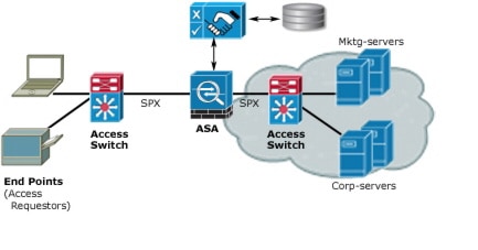
Security Group Policy Enforcement
Security policy enforcement is based on security group name. Compared to traditional IP-based policies configured on firewalls, identity-based policies are configured based on user and device identities. For example, mktg-contractor is allowed to access mktg-servers; mktg-corp-users are allowed to access mktg-server and corp-servers.
The benefits of this type of deployment include:
- User group and Resource is defined and enforced using a single object (SGT) - simplified policy management.
- User identity and resource identity are retained throughout the Cisco Trustsec capable switch infrastructure.
Figure 14-1 Security Group Name Based Policy Enforcement Deployment
Implementing Cisco TrustSec allows you to configure security policies that support server segmentation and includes the following features:
- A pool of servers can be assigned an SGT for simplified policy management.
- The SGT information is retained within the infrastructure of Cisco Trustsec capable switches.
- The ASA, ISR, and ASR can leverage the IP-SGT mapping for policy enforcement across the Cisco TrustSec domain.
- Deployment simplification is possible because 802.1x authorization for servers is mandatory.
How the ASA Enforces Security Group Based Policies
Note![]() User-based security policies and security-group based policies can coexist on the ASA. Any combination of network, user-based, and security-group based attributes can be configured in a security policy.
User-based security policies and security-group based policies can coexist on the ASA. Any combination of network, user-based, and security-group based attributes can be configured in a security policy.
To configure the ASA to function with Cisco TrustSec, you must import a Protected Access Credential (PAC) file from the ISE.
Importing the PAC file to the ASA establishes a secure communication channel with the ISE. After the channel is established, the ASA initiates a PAC secure RADIUS transaction with the ISE and downloads Cisco TrustSec environment data (that is, the security group table). The security group table maps SGTs to security group names. Security group names are created on the ISE and provide user-friendly names for security groups.
Note![]() For more information about the Cisco Identity Services Engine, see http://www.cisco.com/en/US/products/ps11640/index.html.
For more information about the Cisco Identity Services Engine, see http://www.cisco.com/en/US/products/ps11640/index.html.
The first time that the ASA downloads the security group table, it walks through all entries in the table and resolves all the security group names included in security policies that have been configured on it; then the ASA activates those security policies locally. If the ASA cannot resolve a security group name, it generates a syslog message for the unknown security group name.
The following figure shows how a security policy is enforced in Cisco TrustSec.
Figure 14-2 Security Policy Enforcement
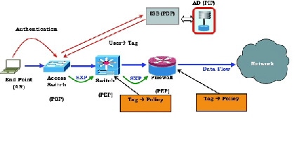
1.![]() An end-point device connects to an access layer device directly or via remote access and authenticates with Cisco TrustSec.
An end-point device connects to an access layer device directly or via remote access and authenticates with Cisco TrustSec.
2.![]() The access layer device authenticates the end-point device with the ISE by using authentication methods such as 802.1X or web authentication. The end-point device passes role and group membership to classify the device into the appropriate security group.
The access layer device authenticates the end-point device with the ISE by using authentication methods such as 802.1X or web authentication. The end-point device passes role and group membership to classify the device into the appropriate security group.
3.![]() The access layer device uses SXP to propagate the IP-SGT mapping to the upstream devices.
The access layer device uses SXP to propagate the IP-SGT mapping to the upstream devices.
4.![]() The ASA receives the packet and looks up the SGTs for the source and destination IP addresses using the IP-SGT mapping passed by SXP.
The ASA receives the packet and looks up the SGTs for the source and destination IP addresses using the IP-SGT mapping passed by SXP.
If the mapping is new, the ASA records it in its local IP-SGT Manager database. The IP-SGT Manager database, which runs in the control plan, tracks IP-SGT mappings for each IPv4 or IPv6 address. The database records the source from which the mapping was learned. The peer IP address of the SXP connection is used as the source of the mapping. Multiple sources can exist for each IP-SGT mapping.
If the ASA is configured as a Speaker, the ASA transmits all IP-SGT mappings to its SXP peers. See About Speaker and Listener Roles.
5.![]() If a security policy is configured on the ASA with that SGT or security group name, the ASA enforces the policy. (You can create security policies on the ASA that include SGTs or security group names. To enforce policies based on security group names, the ASA needs the security group table to map security group names to SGTs.)
If a security policy is configured on the ASA with that SGT or security group name, the ASA enforces the policy. (You can create security policies on the ASA that include SGTs or security group names. To enforce policies based on security group names, the ASA needs the security group table to map security group names to SGTs.)
If the ASA cannot find a security group name in the security group table and it is included in a security policy, the ASA considers the security group name unknown and generates a syslog message. After the ASA refreshes the security group table from the ISE and learns the security group name, the ASA generates a syslog message indicating that the security group name is known.
About Speaker and Listener Roles
The Security-group eXchange Protocol (SXP) is used to send and receive IP-SGT mappings to and from other network devices. Employing SXP allows security devices and firewalls to learn identity information from access switches without the need for hardware upgrades or changes. SXP can also be used to pass IP-SGT mappings from upstream devices (such as datacenter devices) back to the downstream devices.
When configuring an SXP connection to an SXP peer, you must designate the device as a Speaker or a Listener for that connection so that it can exchange identity information:
- Speaker mode—configures the device so that it can forward all active IP-SGT mappings to upstream devices for policy enforcement.
- Listener mode—configures the device so that it can receive IP-SGT mappings from downstream devices (SGT-capable switches) and use that information in creating policy definitions.
If one end of an SXP connection is configured as Speaker, then the other end must be configured as a Listener, and vice versa. If both devices on each end of an SXP connection are configured with the same role (either both as Speakers or both as Listeners), the SXP connection will fail and the device will generate a system log message.
Configuring the device to be both a Speaker and a Listener for an SXP connection can cause SXP looping, meaning that SXP data can be received by an SXP peer that originally transmitted it.
As part of configuring SXP, you configure an SXP reconcile timer. After an SXP peer terminates its SXP connection, the device starts a hold down timer. Only SXP peers designated as Listener devices can terminate a connection. If an SXP peer connects while the hold down timer is running, the device starts the reconcile timer; then, the device updates the IP-SGT mapping database to learn the latest mappings.
Prerequisites for Integrating an ASA with Cisco TrustSec
Before configuring the ASA to integrate with Cisco TrustSec, you must perform the following prerequisites:
- Register the ASA with the ISE.
- Create a security group for the ASA on the ISE.
- Generate the PAC file on the ISE to import into the ASA.
Registering the ASA with the ISE
The ASA must be configured as a recognized Cisco TrustSec network device in the ISE before the ASA can successfully import a PAC file.
2.![]() Choose Administration > Network Devices > Network Devices.
Choose Administration > Network Devices > Network Devices.
4.![]() Enter the IP address of the ASA.
Enter the IP address of the ASA.
5.![]() When the ISE is being used for user authentication in the Cisco TrustSec solution, enter a shared secret in the Authentication Settings area.
When the ISE is being used for user authentication in the Cisco TrustSec solution, enter a shared secret in the Authentication Settings area.
When you configure the AAA sever on the ASA, provide the shared secret you create here on the ISE. The AAA server on the ASA uses this shared secret to communicate with the ISE.
6.![]() Specify a device name, device ID, password, and a download interval for the ASA. See the ISE documentation for the details to perform these tasks.
Specify a device name, device ID, password, and a download interval for the ASA. See the ISE documentation for the details to perform these tasks.
Creating a Security Group on the ISE
When configuring the ASA to communicate with the ISE, you specify a AAA server. When configuring the AAA server on the ASA, you must specify a server group.
The security group must be configured to use the RADIUS protocol.
2.![]() Choose Policy > Policy Elements > Results > Security Group Access > Security Group.
Choose Policy > Policy Elements > Results > Security Group Access > Security Group.
3.![]() Add a security group for the ASA. (Security groups are global and not ASA specific.)
Add a security group for the ASA. (Security groups are global and not ASA specific.)
The ISE creates an entry under Security Groups with a tag.
4.![]() Under the Security Group Access section, configure a device ID credentials and password for the ASA.
Under the Security Group Access section, configure a device ID credentials and password for the ASA.
Before generating the PAC file, you must have registered the ASA with the ISE.
2.![]() Choose Administration > Network Resources > Network Devices.
Choose Administration > Network Resources > Network Devices.
3.![]() From the list of devices, select the ASA device.
From the list of devices, select the ASA device.
4.![]() Under the Security Group Access (SGA), click Generate PAC.
Under the Security Group Access (SGA), click Generate PAC.
5.![]() To encrypt the PAC file, enter a password.
To encrypt the PAC file, enter a password.
The password (or encryption key) you enter to encrypt the PAC file is independent of the password that was configured on the ISE as part of the device credentials.
The ISE generates the PAC file. The ASA can import the PAC from flash or from a remote server via TFTP, FTP, HTTP, HTTPS, or SMB. (The PAC does not have to reside on the ASA flash before you can import it.)
Configuring TrustSec Firewall Policies
Security group awareness is integrated into several existing firewall rules; there is no unique TrustSec firewall policy. Additionally, supporting tools have been updated to work on TrustSec firewall policies. For example, you can search for rules that include a specific Security Group using the Find and Replace tool.
The topics in this section explain the various procedures for integrating security group awareness into firewall policies.
This section contains the following topics:
- Configuring Cisco TrustSec Services
- Creating Security Group Objects
- Selecting Security Groups in Policies
- Configuring TrustSec-Based Firewall Rules
Configuring Cisco TrustSec Services
This procedure explains how to enable and configure Cisco TrustSec in Cisco Security Manager and on the required security devices.
Before configuring an ASA to integrate with Cisco TrustSec, you must meet the prerequisites explained in Prerequisites for Integrating an ASA with Cisco TrustSec.
To configure Cisco TrustSec, perform the following tasks:
Step 1![]() Configure communication between Cisco Security Manager and the Cisco Identity Services Engine (ISE). See ISE Settings Page.
Configure communication between Cisco Security Manager and the Cisco Identity Services Engine (ISE). See ISE Settings Page.
Note![]() Security Manager supports communications with only one ISE appliance/server for fetching and resolving security group names and tags.
Security Manager supports communications with only one ISE appliance/server for fetching and resolving security group names and tags.
Step 2![]() Enable and set the default values for the Security Exchange Protocol (SXP). See Configuring Security Exchange Protocol (SXP) Settings.
Enable and set the default values for the Security Exchange Protocol (SXP). See Configuring Security Exchange Protocol (SXP) Settings.
Step 3![]() Add SXP connection peers for the Cisco TrustSec architecture. See Defining SXP Connection Peers.
Add SXP connection peers for the Cisco TrustSec architecture. See Defining SXP Connection Peers.
Step 4![]() (ASA 9.3.1+ devices only) Configure Security Group Tagging options. See Add/Edit Interface Dialog Box: Advanced Tab (ASA/PIX 7.0+).
(ASA 9.3.1+ devices only) Configure Security Group Tagging options. See Add/Edit Interface Dialog Box: Advanced Tab (ASA/PIX 7.0+).
Step 5![]() (ASA 9.3.1+ devices only) Configure Security Group Tagging for VPN sessions. See ASA Group Policies SSL VPN Full Client Settings.
(ASA 9.3.1+ devices only) Configure Security Group Tagging for VPN sessions. See ASA Group Policies SSL VPN Full Client Settings.
Step 6![]() Configure the Security Policy. See Configuring TrustSec-Based Firewall Rules.
Configure the Security Policy. See Configuring TrustSec-Based Firewall Rules.
Step 7![]() Monitor the TrustSec firewall system. See Monitoring TrustSec Firewall Policies.
Monitor the TrustSec firewall system. See Monitoring TrustSec Firewall Policies.
Configuring Security Exchange Protocol (SXP) Settings
Use the SXP Settings page to enable the Security Exchange Protocol (SXP) on your security device and to configure SXP settings for the device.
Note![]() All settings are available on the SXP Settings page whether you access that page from Policy view or from Device view for a specific device type. If you configure a setting that is not supported on a particular device, you will receive a validation warning and the unsupported CLI will not be generated for the device.
All settings are available on the SXP Settings page whether you access that page from Policy view or from Device view for a specific device type. If you configure a setting that is not supported on a particular device, you will receive a validation warning and the unsupported CLI will not be generated for the device.
- (Device view) Select the security device, then select TrustSec > SXP Settings from the Policy selector.
- (Policy view) Select TrustSec > SXP Settings from the Policy selector. Select an existing policy or create a new one.
|
|
|
|---|---|
Whether to enable the Security Exchange Protocol on the device. The default is disabled |
|
The default time interval between attempts to set up new SXP connections between SXP peers. Enter the retry timer value as a number of seconds in the range of 0 to 64000 seconds. If you specify 0 seconds, the timer never expires and the device will not attempt to connect to SXP peers. By default, the timer value is 120 seconds. The device will continue to attempt to connect to new SXP peers until a successful connection is made. The retry timer is triggered as long as there is one SXP connection on the device that is not up. When the retry timer expires, the device goes through the connection database and if the database contains any connections that are off or in a "pending on" state, the device restarts the retry timer. |
|
The reconcile timer value as a number of seconds in the range of 0 to 64000 seconds. By default, the timer value is 120 seconds. After an SXP peer terminates its SXP connection, the security device starts a hold down timer. If an SXP peer reconnects while the hold down timer is running, the device starts the reconcile timer; then, the device updates the SXP mapping database to learn the latest mappings. When the reconcile timer expires, the device scans the SXP mapping database to identify stale mapping entries (entries that were learned in a previous connection session). The device marks these connections as obsolete. When the reconcile timer expires, the device removes the obsolete entries from the SXP mapping database. Note Setting the reconciliation period to 0 seconds disables the timer and causes all entries from the previous connection to be removed. |
|
The Network Map argument specifies the maximum number of subnet IP hosts from 0 to 65,535 that can be bound to SGTs and exported to the SXP listener. The default is 0 (no expansions performed). |
|
Enter or select the name of the security group created on the ISE for the device. Note If you choose to select a server group, you are also give the option to add a AAA Server group. The server group name you specify here must match the name of the security group created on the ISE for the device. If these two group names do not match, the device will not be able to communicate with the ISE. Contact your ISE administrator if you do not have this information. |
|
|
|
|
Whether to enable logging for IP-to-SGT binding changes causing SXP syslogs (sev 5 syslog) to be generated whenever a change to IP-to-SGT binding occurs (add, delete, change). These changes are learned and propagated on the SXP connection. This logging function is disabled by default. |
|
Whether to enable caching of TrustSec authorization and environment data information to DRAM and NVRAM. To have DRAM cache updates written to non-volatile storage and to enable the DRAM cache to be initially populated from non-volatile storage when the device boots, select the desired file system from the Cache NV Storage list. Options include: |
|
Enter a number from 1-65533 to manually assign a Security Group Tag (SGT) number for this device. |
|
Specifies how long a server in the group should not be selected for service once it has been marked as dead. The default is 20 seconds; the range is 1 to 864000. |
|
Whether to configure RADIUS server group load balancing. When Load Balance is enabled, the following options can be specified: Batch size—The number of transactions to be assigned per batch. The default transactions is 25. Note Changes in batch size may impact CPU load and network throughput. As batch size increases, CPU load decreases and network throughput increases. However, if a large batch size is used, all available server resources may not be fully utilized. As batch size decreases, CPU load increases, and network throughput decreases. It is recommended that the default batch size, 25, be used because it is optimal for high throughput, without adversely impacting CPU load. Ignore Preferred-Server—Instructs the device not to try to use the same server throughout a session. |
|
| (ASA 9.3(1)+, IOS15.2(2)T+, and IOS-XE3.5.x(15.2(1)S)+ only) |
Use the SGT Rolebased Map table to manually map Security Group Tag (SGT) numbers to individual IP addresses or host objects.
|
Add/Edit SGT Role Dialog Box
Use the Add/Edit SGT Role dialog box to manually map Security Group Tag (SGT) numbers to individual IP addresses or host objects.
- (Device view) Select an ASA, ISR, or ASR, then select TrustSec > SXP Settings from the Policy selector.
–![]() To add an entry, click the Add Row (+) button beneath the SGT Rolebased Map table.
To add an entry, click the Add Row (+) button beneath the SGT Rolebased Map table.
–![]() To edit an entry, select it and click the Edit Row (pencil) button beneath the SGT Rolebased Map table.
To edit an entry, select it and click the Edit Row (pencil) button beneath the SGT Rolebased Map table.
- (Policy view) Select TrustSec > SXP Settings from the Policy selector. Select an existing policy or create a new one.
–![]() To add an entry, click the Add Row (+) button beneath the SGT Rolebased Map table.
To add an entry, click the Add Row (+) button beneath the SGT Rolebased Map table.
–![]() To edit an entry, select it and click the Edit Row (pencil) button beneath the SGT Rolebased Map table.
To edit an entry, select it and click the Edit Row (pencil) button beneath the SGT Rolebased Map table.
Defining SXP Connection Peers
The Security-group eXchange Protocol (SXP) is a protocol developed for Cisco TrustSec to propagate the IP-to-SGT mapping database across network devices that do not have SGT-capable hardware support to hardware that supports SGTs and security group ACLs. SXP, a control plane protocol, passes IP-SGT mappings from authentication points (such as legacy access layer switches) to upstream devices in the network. SXP connections between peers are point-to-point and use TCP as the underlying transport protocol.
- Prerequisites for Integrating an ASA with Cisco TrustSec
- About Speaker and Listener Roles
- Configuring Security Exchange Protocol (SXP) Settings
Step 1![]() Do one of the following:
Do one of the following:
- (Device view) Select an ASA, ISR, or ASR, then select TrustSec > SXP Connection Peers from the Policy selector.
- (Policy view) Select TrustSec > SXP Connection Peers from the Policy selector. Select an existing policy or create a new one.
Step 2![]() In Default Source, enter the default local IP address for SXP connections. You can enter an IP address or the name of a network/host object, or click Select to select the object from a list or to create a new one. The IP address can be an IPv4 or IPv6 address.
In Default Source, enter the default local IP address for SXP connections. You can enter an IP address or the name of a network/host object, or click Select to select the object from a list or to create a new one. The IP address can be an IPv4 or IPv6 address.
Note![]() The device determines the local IP address for an SXP connection as the outgoing interface IP address that is reachable by the peer IP address. If the configured local address is different from the outgoing interface IP address, the device cannot connect to the SXP peer and generates a system log message.
The device determines the local IP address for an SXP connection as the outgoing interface IP address that is reachable by the peer IP address. If the configured local address is different from the outgoing interface IP address, the device cannot connect to the SXP peer and generates a system log message.
Step 3![]() In Default Password and Confirm, enter the default password for TCP MD5 authentication with SXP peers. By default, SXP connections do not have a password set.
In Default Password and Confirm, enter the default password for TCP MD5 authentication with SXP peers. By default, SXP connections do not have a password set.
You can specify the password as an encrypted string up to 162 characters or an ASCII key string up to 80 characters.
Step 4![]() Configure the SXP Peers:
Configure the SXP Peers:
- To add an entry, click the Add Row (+) button and fill in the Add Connection Peer dialog box. See Add/Edit Connection Peer Dialog Box.
- To edit an entry, select it and click the Edit Row (pencil) button.
- To delete an entry, select it and click the Delete Row (trash can) button.
Step 5![]() Click Save to save your changes.
Click Save to save your changes.
Add/Edit Connection Peer Dialog Box
Use the Add/Edit Connection Peer dialog box to define the settings for an SXP Connection.
Note![]() All settings are available on the Add/Edit Connection Peer dialog box whether you access that dialog box from Policy view or from Device view for a specific device type. If you configure a setting that is not supported on a particular device, you will receive a validation warning and the unsupported CLI will not be generated for the device.
All settings are available on the Add/Edit Connection Peer dialog box whether you access that dialog box from Policy view or from Device view for a specific device type. If you configure a setting that is not supported on a particular device, you will receive a validation warning and the unsupported CLI will not be generated for the device.
- (Device view) Select an ASA, ISR, or ASR, then select TrustSec > SXP Connection Peers from the Policy selector.
–![]() To add an entry, click the Add Row (+) button.
To add an entry, click the Add Row (+) button.
–![]() To edit an entry, select it and click the Edit Row (pencil) button.
To edit an entry, select it and click the Edit Row (pencil) button.
- (Policy view) Select TrustSec > SXP Connection Peers from the Policy selector. Select an existing policy or create a new one.
–![]() To add an entry, click the Add Row (+) button.
To add an entry, click the Add Row (+) button.
–![]() To edit an entry, select it and click the Edit Row (pencil) button.
To edit an entry, select it and click the Edit Row (pencil) button.
|
|
|
|---|---|
The IPv4 or IPv6 address of the SXP peer. The peer IP address must be reachable from the outgoing interface. You can enter an IP address or the name of a network/host object, or click Select to select the object from a list or to create a new one. |
|
(Optional) The local IPv4 or IPv6 address of the SXP connection. Specifying the source IP address is optional, however, specifying it safeguards misconfiguration. You can enter an IP address or the name of a network/host object, or click Select to select the object from a list or to create a new one. Note You cannot configure the Source IP Address and Peer IP Address with the same address. Also, you cannot use an IPv4 address with one field and an IPv6 address with the other. |
|
Whether to use the authentication key for the SXP connection. Select from the following values:
|
|
The mode of the SXP connection. Select from the following values: |
|
Whether the device functions as a Speaker or Listener for the SXP connection: |
|
The minimum length of the hold-time period in seconds for the speaker or listener device. |
|
The maximum length of the hold-time period in seconds for the speaker or listener device. A hold-time maximum-period value is required only when you use the following option combinations: peer speaker and local listener. In other instances, only a hold-time minimum-period value is required. |
Creating Security Group Objects
You can create security group object groups for use in features that support Cisco TrustSec by including the group in an extended ACL, which in turn can be used in an access rule, for example.
When integrated with Cisco TrustSec, the security device downloads security group information from the Cisco Identity Services Engine (ISE). The ISE acts as an identity repository, by providing Cisco TrustSec tag to user identity mapping and Cisco TrustSec tag to server resource mapping. You provision and manage security group access lists centrally on the ISE.
However, the device might have localized network resources that are not defined globally that require local security groups with localized security policies. Local security groups can contain nested security groups that are downloaded from the ISE. The security device consolidates local and central security groups.
To create local security groups on the device, you create a local security object group. A local security object group can contain one or more nested security object groups or Security IDs or security group names. Users can also create a new Security ID or security group name that does not exist on the device.
You can use the security object groups you create to control access to network resources. You can use the security object group as part of an access group or service policy.
- Use of these objects is supported on ASA 9.0(1)+, IOS 15.2(2)T+, and IOS-XE 3.5.x(15.2(1)S)+ only.
- Although IOS does not support security group object groups, Security Manager allows the use of security group object groups for ISR devices and will automatically expand the object groups to their tag numbers during deployment.
- You must configure the TrustSec policy on the device to enable the use of these objects.
- You can create security group objects when defining policies or objects that use this object type. For more information, see Selecting Security Groups in Policies.
Step 1![]() Select Manage > Policy Objects to open the Policy Object Manager (see Policy Object Manager).
Select Manage > Policy Objects to open the Policy Object Manager (see Policy Object Manager).
Step 2![]() Select Security Group from the Object Type selector.
Select Security Group from the Object Type selector.
Step 3![]() Right-click in the work area, then select New Object to open the Add Security Group dialog box.
Right-click in the work area, then select New Object to open the Add Security Group dialog box.
Step 4![]() Enter a name for the object and optionally a description of the object.
Enter a name for the object and optionally a description of the object.
Step 5![]() Add and remove items in the Members in Group list to identify the users and user groups defined in the object.
Add and remove items in the Members in Group list to identify the users and user groups defined in the object.
To populate the list, do any combination of the following:
- In Available Security Group, select an existing object and click the Add >> button between the lists.
- In Search name/tag, select a security group from the ISE server configured in the ISE Settings administrative options. You must configure the settings before you can select a name or tag (see ISE Settings Page).
To find a security group, enter a search string. Then, click Search to find matches. A name is considered a match if the string appears anywhere within the security group name.
To add the security group, select it in the list and click the Add >> button between the lists.
- In Type in comma separated (Name or Tag), first select the type of entry you are making, Name or Tag. Type in a valid security group name or tag number, then click the Add >> button between the lists. Separate multiple names or tags with commas; they are added as separate lines in the members list. When adding multiple names or tags, avoid adding spaces before or after the comma.
Valid security tag numbers are 0-65533 for ASA 9.3+, 1-65533 for ASA versions less than 9.3, 0-65533 for ISR, and 1-65535 for ASR.
- To remove an item from the object, select it in the Members list and click the << Remove button between the lists.
Note![]() Although IOS and IOS-XE only support security group tags, Security Manager allows the use of security group names for ISR and ASR devices, either directly or as part of a security group object group, and will automatically convert security group names to their tag number during deployment. However, if the ISE is not reachable, Security Manager will not be able to resolve the security group names. In such situations, Security Manager will not generate the rule for the configuration and an appropriate warning/error message will be displayed.
Although IOS and IOS-XE only support security group tags, Security Manager allows the use of security group names for ISR and ASR devices, either directly or as part of a security group object group, and will automatically convert security group names to their tag number during deployment. However, if the ISE is not reachable, Security Manager will not be able to resolve the security group names. In such situations, Security Manager will not generate the rule for the configuration and an appropriate warning/error message will be displayed.
Step 6![]() (Optional) Under Category, select a category to help you identify this object in the Objects table. See Using Category Objects.
(Optional) Under Category, select a category to help you identify this object in the Objects table. See Using Category Objects.
Step 7![]() (Optional) Select Allow Value Override per Device to allow the properties of this object to be redefined on individual devices. See Allowing a Policy Object to Be Overridden.
(Optional) Select Allow Value Override per Device to allow the properties of this object to be redefined on individual devices. See Allowing a Policy Object to Be Overridden.
Step 8![]() Click OK to save the object.
Click OK to save the object.
Selecting Security Groups in Policies
In any policy or policy object that allows the specification of security groups, whether directly or through the selection of a TrustSec security group object, you can click the Select button next to the Security Groups field to help you enter the information.
In the Security Group Selector dialog box, you can define the content of the Security Groups field by populating the Members in Group list. To populate the list, do any combination of the following:
- In Available Security Group, select an existing object and click the Add >> button between the lists. If the desired object does not exist, you can click the Add (+) button below the list to create a new object. You can also select an object and click the Edit (pencil) button to modify it or to examine its contents.
- In Search name/tag, select a security group from the ISE server configured in the ISE Settings administrative options. You must configure the settings before you can select a name or tag (see ISE Settings Page).
To find a security group, enter a search string. Then, click Search to find matches. A name is considered a match if the string appears anywhere within the security group name.
To add the security group, select it in the list and click the Add >> button between the lists.
- In Type in comma separated (Name or Tag), first select the type of entry you are making, Name or Tag. Type in a valid security group name or tag number, then click the Add >> button between the lists. Separate multiple names or tags with commas; they are added as separate lines in the members list. When adding multiple names or tags, avoid adding spaces before or after the comma.
Valid security tag numbers are 0-65533 for ASA 9.3+, 1-65533 for ASA versions less than 9.3, 0-65533 for ISR, and 1-65535 for ASR.
Configuring TrustSec-Based Firewall Rules
Security group awareness is integrated into the access control entries, or rules, in the ACLs used to provide firewall services. Because the feature is integrated into the ACL, the techniques for adding security group awareness to a firewall policy are the same for all types of firewall policy. This topic provides general guidance on how to incorporate security group awareness into your existing policies, and directs you to more specific information on configuring each type of policy that supports security groups.
Firewall Policies That Support Security Groups
For ASA 9.0.1+ only, you can configure security groups for the following policy types:
- AAA Rules—Select Firewall > AAA Rules and see Configuring AAA Rules for ASA, PIX, and FWSM Devices.
- Access Rules—Select Firewall > Access Rules and see Configuring Access Rules.
- Inspection Rules—Select Firewall > Inspection Rules and see Configuring Inspection Rules.
- Policies that use extended ACL policy objects—Several firewall policies use extended ACL policy objects to define traffic matching criteria instead of incorporating a rule table directly in the policy. You can configure extended ACL policy objects to include security group specifications (see Creating Extended Access Control List Objects). You can then use these extended ACL objects in the following policies:
–![]() Botnet Traffic Filter Rules—Select Firewall > Botnet Traffic Filter Rules and see Enabling Traffic Classification and Actions for the Botnet Traffic Filter. You can use security groups as part of the traffic classification for Enable and Drop rules.
Botnet Traffic Filter Rules—Select Firewall > Botnet Traffic Filter Rules and see Enabling Traffic Classification and Actions for the Botnet Traffic Filter. You can use security groups as part of the traffic classification for Enable and Drop rules.
–![]() IPS, QoS, and Connection Rules (service policy rules)—Select Platform > Service Policy Rules > IPS, QoS, and Connection Rules and see Service Policy Rules Page.
IPS, QoS, and Connection Rules (service policy rules)—Select Platform > Service Policy Rules > IPS, QoS, and Connection Rules and see Service Policy Rules Page.
Traffic match criteria in this policy is based on extended ACL policy objects that are incorporated into traffic flow policy objects. You must select one of the options for specifying an ACL in the traffic flow object to incorporate security group traffic classification. For more information, see Configuring Traffic Flow Objects.
For devices running IOS 15.2(2)T+ and IOS-XE 3.5.x(15.2(1)S)+, you can configure security groups for Zone-based Firewall Rules (Firewall > Zone Based Firewall Rules). For more information, see Adding Zone-Based Firewall Rules.
Monitoring TrustSec Firewall Policies
You can use Event Viewer to monitor TrustSec firewall policies the same way you would monitor other types of policies and events. The following are some tips to help you effectively monitor identity policies. For general information on using Event Viewer, see Chapter 69, “Viewing Events”.
- There are groups of syslog messages that relate specifically to Cisco TrustSec: 766001-766020, 766201-766205, 766251-766254, and 766301-766313. You can find descriptions of these messages in the Syslog Message document for your ASA software version at http://www.cisco.com/en/US/products/ps6120/products_system_message_guides_list.html.
- Event Viewer has the following columns to display TrustSec information: TrustSec Security Group Name, TrustSec Security Group Tag, SXP Connection Source IP, SXP Connection Failure Reason, SXP Peer IP, SXP Peer Connection Failure Reason.
- You can filter on all identity-related syslog messages by creating a filter on Event Type and selecting the All Firewall Events > Trustsec Events folder.
 Feedback