Connect to the Appliance

After rack-mounting the appliance, follow these steps to connect cables, turn on power, and verify connectivity.


Note


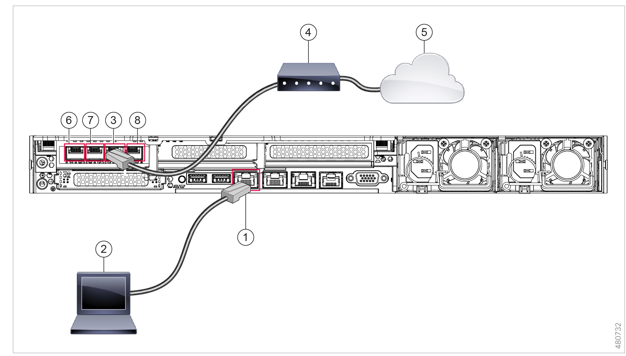
The connection diagram in each topic shows the default configuration using a management computer connected to your private network. Your deployment may vary depending on your basic logical network connectivity, ports, addressing, and configuration requirements.


Cisco S196 Secure Web Appliance

Procedure


Step 1

Plug one end of the straight power cable into the power supply on the back panel of the appliance.

Note


It is optional to order a separate power cable and connect to the second power supply at the back panel of the appliance for redundancy.

Step 2

Plug the other end into an electrical outlet.

Step 3

Plug the Ethernet cables into the appropriate ports on the back panel of the appliance.

  • The proxy ports are P1 and P2.

    • P1 only enabled: When only P1 is enabled, connect it to the network for both incoming and outgoing traffic.

    • P1 and P2 enabled: When both P1 and P2 are enabled, you must connect P1 to the internal network and P2 to the internet.

  • The traffic monitor ports are T1 and T2.

    • Simplex tap: Ports T1 and T2; one cable for all packets destined for the internet (T1) and one cable for all packets coming from the internet (T2).

    • Duplex tap: Port T1; one cable for all incoming and outgoing traffic.

Step 4

Connect your laptop to the Management port (M1) using the Ethernet cable included in the system box.

1

Management port (M1) - (192.168.42.42)

2

Management computer (192.68.42.43)

3

Traffic monitor port 1 (T1)

4

WAN modem

5

Internet

6

Proxy port 1 (P1)

7

Proxy port 2 (P2)

8

Traffic monitor port 2 (T2)

Step 5

Power up the appliance by pressing the On/Off switch on the front panel of the appliance. You must wait 10 minutes for the system to initialize each time you power up the system. After the appliance powers up, a solid green light on the front panel indicates that the appliance is operational.

Caution


If you turn the power off before the initialization is complete, the appliance will not reach an operational state and must be returned to Cisco.

Note


If turned on quickly after connecting power to the appliance, the appliance powers up, the fans spin and the LEDs turn on. Within 30-60 seconds, the fans stop and all LEDs turn off. The appliance powers on 31 seconds later. This behavior is by design to allow the system firmware and controller to synchronize.

Step 6

See the AsyncOS for Cisco Web Security Appliances User Guide for further configuration.


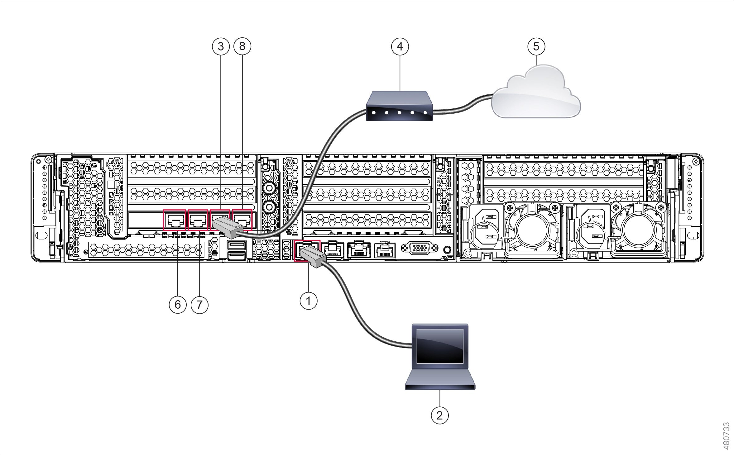
Cisco S396 Secure Web Appliance

Procedure


Step 1

Plug one end of each straight power cable into the redundant power supplies on the back panel of the appliance.

Step 2

Plug the other end into an electrical outlet.

Step 3

Plug the Ethernet cables into the appropriate ports on the back panel of the appliance.

  • The proxy ports are P1 and P2.

    • P1 only enabled: When only P1 is enabled, connect it to the network for both incoming and outgoing traffic.

    • P1 and P2 enabled: When both P1 and P2 are enabled, you must connect P1 to the internal network and P2 to the internet.

  • The traffic monitor ports are T1 and T2.

    • Simplex tap: Ports T1 and T2; one cable for all packets destined for the internet (T1) and one cable for all packets coming from the internet (T2).

    • Duplex tap: Port T1; one cable for all incoming and outgoing traffic.

Step 4

Connect your laptop to the Management port using the Ethernet cable included in the system box. The S-Series appliance uses the M1 Management port only.

1

Management Port (M1) - (192.168.42.42)

2

Management Computer (192.168.42.43)

3

Traffic Monitor Port 1 (T1)

4

WAN Modem

5

Internet

6

Proxy port 1 (P1)

7

Proxy port 2 (P2)

8

Traffic monitor port 2 (T2)

Step 5

Power up the appliance by pressing the On/Off switch on the front panel of the appliance. You must wait 10 minutes for the system to initialize each time you power up the system. After the appliance powers up, a solid green light on the front panel indicates that the appliance is operational.

Caution


If you turn the power off before the initialization is complete, the appliance will not reach an operational state and must be returned to Cisco.

Note


If turned on quickly after connecting power to the appliance, the appliance powers up, the fans spin and the LEDs turn on. Within 30-60 seconds, the fans stop and all LEDs turn off. The appliance powers on 31 seconds later. This behavior is by design to allow the system firmware and controller to synchronize.

Step 6

See the AsyncOS for Cisco Web Security Appliances User Guide for further configuration.


Cisco S696 Secure Web Appliance

Procedure


Step 1

Plug one end of each straight power cable into the redundant power supplies on the back panel of the appliance.

Step 2

Plug the other end into an electrical outlet.

Step 3

Plug the Ethernet cables into the appropriate ports on the back panel of the appliance.

  • The proxy ports are P1 and P2.

    • P1 only enabled: When only P1 is enabled, connect it to the network for both incoming and outgoing traffic.

    • P1 and P2 enabled: When both P1 and P2 are enabled, you must connect P1 to the internal network and P2 to the internet.

  • The traffic monitor ports are T1 and T2.

    • Simplex tap: Ports T1 and T2; one cable for all packets destined for the internet (T1) and one cable for all packets coming from the internet (T2).

    • Duplex tap: Port T1; one cable for all incoming and outgoing traffic.

Step 4

Connect your laptop to the Management port using the Ethernet cable included in the system box.

1

Management port (M1) - (192.168.42.42)

2

Management computer (192.168.42.43)

3

Traffic monitor port (T1)

4

WAN modem

5

Internet

6

Proxy port 1 (P1)

7

Proxy port 2 (P2)

8

Traffic monitor port 2 (T2)

Step 5

Power up the appliance by pressing the On/Off switch on the front panel of the appliance. You must wait 10 minutes for the system to initialize each time you power up the system. After the appliance powers up, a solid green light on the front panel indicates that the appliance is operational.

Caution


Wait at least 10 minutes for the system to complete the power up sequence and the LEDs to turn green. If you turn the power off before the initialization is complete, the appliance will not reach an operational state and must be returned to Cisco.

Note


If turned on quickly after connecting power to the appliance, the appliance powers up, the fans spin and the LEDs turn on. Within 30-60 seconds, the fans stop and all LEDs turn off. The appliance powers on 31 seconds later. This behavior is by design to allow the system firmware and controller to synchronize.

Step 6

See the AsyncOS for Cisco Web Security Appliances User Guide for further configuration.


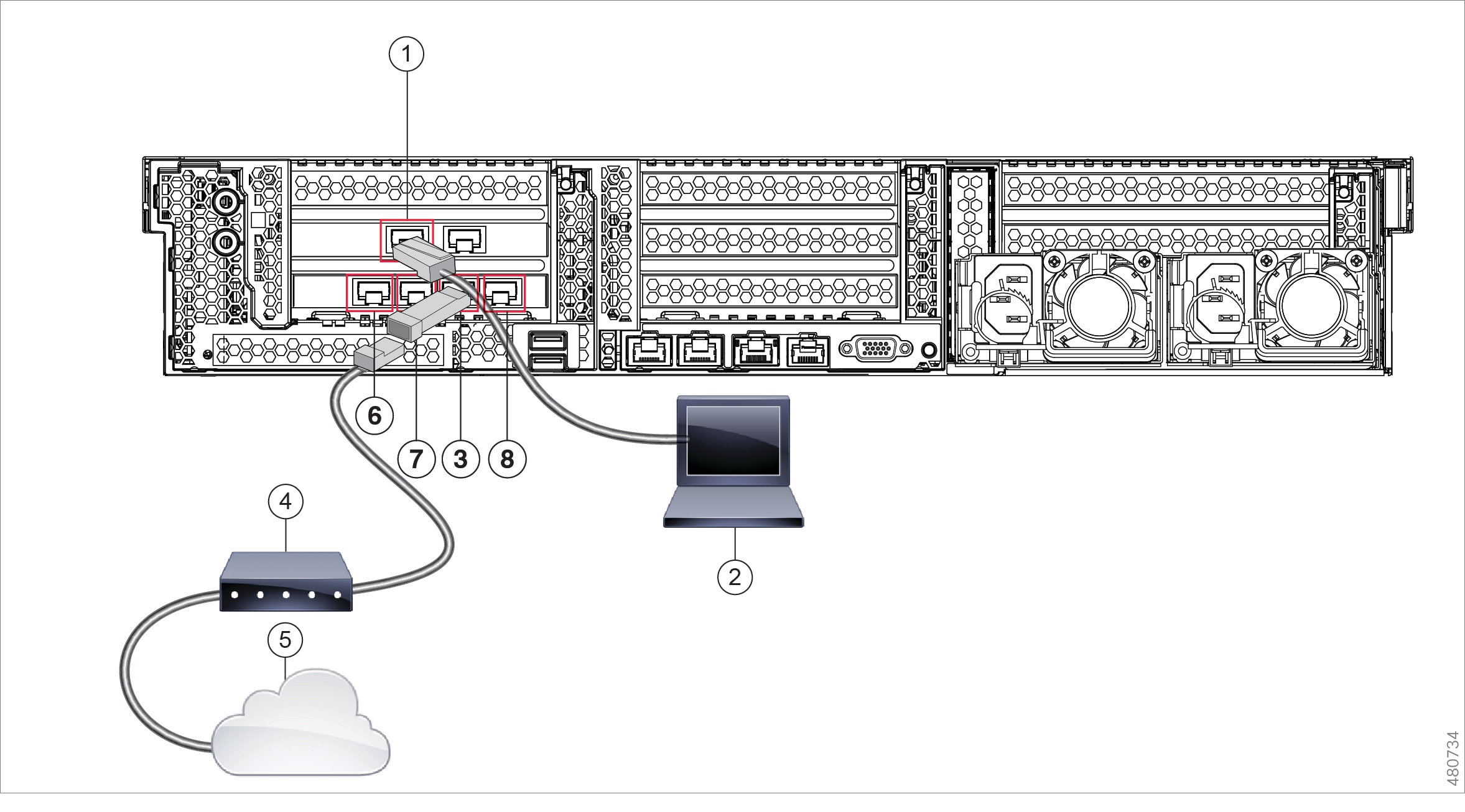
Cisco S696F Secure Web Appliance

The following illustration shows the Cisco S696F model with fiber optic ports. These fiber optic ports are located above the Ethernet ports shown in the illustration, and the Ethernet ports are not present. For details, see the Cisco x96 Secure Web Appliances Installation and Maintenance Guide.

The top two fiber optic ports are used as proxy ports in the same way as the Ethernet proxy ports described in the following table. The middle two fiber optic ports are used as traffic ports. The bottom two fiber optic ports are used as Management ports.

Procedure


Step 1

Plug one end of each straight power cable into the redundant power supplies on the back panel of the appliance.

Step 2

Plug the other end into an electrical outlet.

Step 3

Plug the Ethernet cables into the appropriate ports on the back panel of the appliance.

  • The proxy ports are P1 and P2.

    • P1 only enabled: When only P1 is enabled, connect it to the network for both incoming and outgoing traffic.

    • P1 and P2 enabled: When both P1 and P2 are enabled, you must connect P1 to the internal network and P2 to the Internet.

  • The traffic monitor ports are T1 and T2.

    • Simplex tap: Ports T1 and T2; one cable for all packets destined for the internet (T1) and one cable for all packets coming from the internet (T2).

    • Duplex tap: Port T1; one cable for all incoming and outgoing traffic.

Step 4

Connect your laptop to the Management port using the Ethernet cable included in the system box.

Caution


Use only the transceiver modules supplied with the 10-Gigabit fiber optic interfaces. The use of any other transceiver modules may damage the fiber optic interface card.

1

Management port (M1) - (192.168.42.42)

2

Management computer (192.168.42.43)

3

Traffic monitor port (T1)

4

WAN modem

5

Internet

6

Proxy port 1 (P1)

7

Proxy port 2 (P2)

8

Traffic monitor port 2 (T2)

Step 5

Power up the appliance by pressing the On/Off switch on the front panel of the appliance. You must wait 10 minutes for the system to initialize each time you power up the system. After the appliance powers up, a solid green light on the front panel indicates that the appliance is operational.

Caution


Wait at least 10 minutes for the system to complete the power up sequence and the LEDs to turn green. If you turn the power off before the initialization is complete, the appliance will not reach an operational state and must be returned to Cisco.

Note


If turned on quickly after connecting power to the appliance, the appliance powers up, the fans spin and the LEDs turn on. Within 30-60 seconds, the fans stop and all LEDs turn off. The appliance powers on 31 seconds later. This behavior is by design to allow the system firmware and controller to synchronize.

Step 6

See the AsyncOS for Cisco Web Security Appliances User Guide for further configuration.