Microsoft Hyper-V and Nexus 1000V Switch for Microsoft Hyper-V within a VMDC Architecture
Bias-Free Language
The documentation set for this product strives to use bias-free language. For the purposes of this documentation set, bias-free is defined as language that does not imply discrimination based on age, disability, gender, racial identity, ethnic identity, sexual orientation, socioeconomic status, and intersectionality. Exceptions may be present in the documentation due to language that is hardcoded in the user interfaces of the product software, language used based on RFP documentation, or language that is used by a referenced third-party product. Learn more about how Cisco is using Inclusive Language.
- Updated:
- September 17, 2013
Chapter: Nexus 1000V Switch for Microsoft Hyper-V Configuration
Nexus 1000V Switch for Microsoft Hyper-V Configuration
This section describes how to configure the Nexus 1000V Switch for Microsoft Hyper-V in a VMDC solution.
•![]() VSM CLI Configuration
VSM CLI Configuration
•![]() SCVMM Configuration
SCVMM Configuration
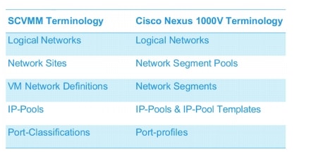
Figure 3-1 compares the SCVMM and Nexus 1000V Switch for Microsoft Hyper-V terminology that will be referenced in each section.
The reader should be familiar with these terms to better understand the role of each object as it pertains to the entire configuration and how each relates to SCVMM and the Nexus 1000V Switch for Microsoft Hyper-V.
Figure 3-1 SCVMM and Nexus 1000V Switch for Microsoft Hyper-V Terminology
Network and Tenants Under Test
Three private tenants and one public tenant logical networks were created.
Six network segment pools were created, three public (T1, T2, T3) and three private (PT1, PT2, PT3). The three public network segment pools were configured as members of the public tenant logical network; the three private network segment pools were each configured as an individual member of a the three private tenant logical networks.
Only one network segment per public network segment pool was created. Two network segments per private network segment pool were created.
The IP pool templates and port-profiles are described in the IP Pool templates and Port-profiles sections later in the doc.
The configuration looks like this:
logical network PublicTenants
network segment pool T1
network segment T1-NetworkSegment101
network segment pool T2
network segment T2-NetworkSegment102
network segment pool T3
network segment T3-NetworkSegment103
logical network PrivateTenant1
network segment pool PT1
network segment PT1-NetworkSegment2013
network segment PT1-NetworkSegment2014
logical network PrivateTenant3
network segment pool PT2
network segment PT2-NetworkSegment2023
network segment PT2-NetworkSegment2024
logical network PrivateTenant3
network segment pool PT3
network segment PT3-NetworkSegment2033
network segment PT3-NetworkSegment2034
Refer to Cisco Nexus 1000V for Microsoft Hyper-V Network Segmentation Manager Configuration Guide for more information about Microsoft networking concepts, command details, and implementation.
Refer to Cisco Nexus 1000V for Microsoft Hyper-V Release Notes, Release 5.2(1)SM1(5.1) for new features and caveats.
Nexus 1000V Switch for Microsoft Hyper-V VSM CLI Configuration
This section describes how to configure the Nexus 1000V with Hyper-V using the Network Segmentation Manager (NSM) CLI on the VSM.
Step 1 ![]() Create Logical Networks.
Create Logical Networks.
A logical network (for example, internet, intranet, DMZ) is a connectivity abstraction that models separate networks managed by an enterprise. Logical network abstraction hides VLANs and IP subnets from users (VM network administrators, the tenant administrators, and the server administrators), except for the fabric administrator managing the physical fabric.
In other words, a logical network is composed of one or more network segment pools and each network segment pool is a group of VLANS, IP subnets, or VLAN/IP subnet pairs.
The following logical networks configuration shows three private tenants and one public tenant.
nsm logical network PublicTenants
nsm logical network PrivateTentant1
nsm logical network PrivateTentant2
nsm logical network PrivateTentant3
Step 2 ![]() Create Network Segments Pools.
Create Network Segments Pools.
A network segment is associated with a unique broadcast domain and facilitates the availability of the network resources to a VM. SCVMM uses the VM networks and the VM subnets to provide the isolated virtual machine networks.
When a Nexus 1000V manages the virtual network, the VMM administrator creates the VM networks that use external isolation. To create external isolation, the network administrator creates network segments on the Nexus 1000V and provisions the isolated networks using VLANs and private VLANs.

Note ![]() In Nexus 1000V for Microsoft Hyper-V, a VLAN is not created to define a bridge domain. Instead, a network segment is created on the VSM. Creating a network segment triggers VLAN auto-creation.
In Nexus 1000V for Microsoft Hyper-V, a VLAN is not created to define a bridge domain. Instead, a network segment is created on the VSM. Creating a network segment triggers VLAN auto-creation.
The following configuration shows network segment pools.
nsm network segment pool T1
nsm network segment pool T2
nsm network segment pool T3
nsm network segment pool PT1
nsm network segment pool PT2
nsm network segment pool PT3
Step 3 ![]() Add each Network Segment Pool to the Logical Network.
Add each Network Segment Pool to the Logical Network.
The T1, T2, and T3 segment pools are members of the same public tenant logical network. The PT1, PT2, and PT3 segment pools are members of unique logical networks.
The following configuration shows mapping for network segment pools into logical networks.
nsm network segment pool T1
member-of logical network PublicTenants
nsm network segment pool T2
member-of logical network PublicTenants
nsm network segment pool T3
member-of logical network PublicTenants
nsm network segment pool PT1
member-of logical network PrivateTentant1
nsm network segment pool PT2
member-of logical network PrivateTentant2
nsm network segment pool PT3
member-of logical network PrivateTentant3
Step 4 ![]() Create IP Pool Templates.
Create IP Pool Templates.
Server administrators can manage IP addresses for the virtual environment using IP pool templates. You can use the IP pool templates to assign a range of IP addresses to hosts and VMs in the Microsoft SCVMM-managed environment. When creating an IP pool template for a VM network, you can define a range of IP addresses for VMs managed by SCVMM.
The following configurations shows IP pool templates that were created.
nsm ip pool template PT1-VL2013-IP-Pool
ip address 200.1.3.2 200.1.3.250
network 200.1.3.0 255.255.255.0
default-router 200.1.3.253
nsm ip pool template PT1-VL2014-IP-Pool
ip address 200.1.4.2 200.1.4.250
network 200.1.4.0 255.255.255.0
default-router 200.1.4.253
nsm ip pool template PT2-VL2023-IP-Pool
ip address 200.2.3.2 200.2.3.250
network 200.2.3.0 255.255.255.0
default-router 200.2.3.253
nsm ip pool template PT2-VL2024-IP-Pool
ip address 200.2.4.2 200.2.4.250
network 200.2.4.0 255.255.255.0
default-router 200.2.4.253
nsm ip pool template PT3-VL2033-IP-Pool
ip address 200.3.3.2 200.3.3.250
network 200.3.3.0 255.255.255.0
default-router 200.3.3.253
nsm ip pool template PT3-VL2034-IP-Pool
ip address 200.3.4.2 200.3.4.250
network 200.3.4.0 255.255.255.0
default-router 200.3.4.253
nsm ip pool template T1-VL101-IP-Pool
ip address 10.101.1.2 10.101.1.250
network 10.101.1.0 255.255.255.0
default-router 10.101.1.253
nsm ip pool template T2-VL102-IP-Pool
ip address 10.102.1.2 10.102.1.250
network 10.102.1.0 255.255.255.0
default-router 10.102.1.253
nsm ip pool template T3-VL103-IP-Pool
ip address 10.103.1.2 10.103.1.250
network 10.103.1.0 255.255.255.0
default-router 10.103.1.253
Step 5 ![]() Create Network Segments.
Create Network Segments.
Configure each network segment to be a member of the previously configured network segment pools. Configure each network segment as an access port with an access VLAN. Import the previously configured IP pool for each network segment. Publish each network segment.
The VM Network Creation. commands are added automatically and appear later in this section when configuring VM networks in SCVMM.
VM networks enable the SCVMM administrator to create an isolated virtual Layer 3 (L3) network. Each VM network can have multiple VM subnets (virtual L2 domain). Microsoft SCVMM 2012 supports VLAN-backed and network virtualization (NVGRE)-backed VM networks. The Nexus 1000V supports VLAN-backed VM networks only.
The following configuration shows network segments that were created.
nsm network segment T1-NetworkSegment101
member-of network segment pool T1
switchport access vlan 101
ip pool import template T1-VL101-IP-Pool
publish network segment
switchport mode access
nsm network segment T2-NetworkSegment102
member-of network segment pool T2
switchport access vlan 102
ip pool import template T2-VL102-IP-Pool
publish network segment
switchport mode access
nsm network segment T3-NetworkSegment103
member-of network segment pool T3
switchport access vlan 103
ip pool import template T3-VL103-IP-Pool
publish network segment
switchport mode access
nsm network segment PT1-NetworkSegment2013
member-of vmnetwork PT1-NetworkSegment2013
member-of network segment pool PT1
switchport access vlan 2013
ip pool import template PT1-VL2013-IP-Pool
publish network segment
switchport mode access
nsm network segment PT1-NetworkSegment2014
member-of network segment pool PT1
switchport access vlan 2014
ip pool import template PT1-VL2014-IP-Pool
publish network segment
switchport mode access
nsm network segment PT2-NetworkSegment2023
member-of network segment pool PT2
switchport access vlan 2023
ip pool import template PT2-VL2023-IP-Pool
publish network segment
switchport mode access
nsm network segment PT2-NetworkSegment2024
member-of network segment pool PT2
switchport access vlan 2024
ip pool import template PT2-VL2024-IP-Pool
publish network segment
switchport mode access
nsm network segment PT3-NetworkSegment2033
member-of network segment pool PT3
switchport access vlan 2033
ip pool import template PT3-VL2033-IP-Pool
publish network segment
switchport mode access
nsm network segment PT3-NetworkSegment2034
member-of network segment pool PT3
switchport access vlan 2034
ip pool import template PT3-VL2034-IP-Pool
publish network segment
switchport mode access
Step 6 ![]() Create Port profiles.
Create Port profiles.
Unlike the Nexus 1000V for ESX, in which a port profile identifies both network policy and network isolation (VLAN), SCVMM networking decouples this information into a VM network and the port classification. When the Nexus 1000V is used with Hyper-V, the network administrator creates network segments to isolate networks. The SCVMM server administrator uses network segments in the resulting VM networks. The network administrator defines creates port profiles to define port policy. The server administrator uses port profiles to create a port classification.
To deploy a VM to the virtual access layer, choose the port classification, VM network, and the VM subnet. When a VM is deployed, a port profile is dynamically created on the Nexus 1000V for each unique combination of port classification, VM network, and VM subnet. All other VMs deployed with the same policy to this network reuse the dynamic port profile, which is a combination of network isolation and network policy.
Note ![]() The generated profile should be neither modified nor inherited in other port profiles.
The generated profile should be neither modified nor inherited in other port profiles.
When a port-attach notification is received, the port profile globally unique identifier (GUID) and network segment GUID are generated. A GUID provides a unique reference for the port profile and the network segment.
When a GUID is generated, a new port profile, combining the port profile and the VLAN, is created on the VSM. This auto-created port-profile is inherited on the interface. If more than one port uses the same combination of port profile and network segment, the port profile is shared. Port profiles are dynamically created during the interface attach process.
The following configuration shows port-profiles that were created.
port-profile type vethernet T1-PortProfile
no shutdown
state enabled
publish port-profile
port-profile type vethernet T2-PortProfile
no shutdown
state enabled
publish port-profile
port-profile type vethernet T3-PortProfile
no shutdown
state enabled
publish port-profile
port-profile type vethernet PT1-PortProfile
no shutdown
state enabled
publish port-profile
port-profile type vethernet PT2-PortProfile
no shutdown
state enabled
publish port-profile
port-profile type vethernet PT3-PortProfile
no shutdown
state enabled
publish port-profile
Step 7 ![]() Create Uplink Port Profile and Network Uplink.
Create Uplink Port Profile and Network Uplink.
An uplink port profile is essentially a template that defines a list of network segment pools to be associated with any (physical) network adapters to which the uplink port profile is applied. An uplink port profile enables you to specify protocols and port policy for the uplink adapter, using an Ethernet port profile to be specified.
The following configuration shows uplink port-profiles.
port-profile type ethernet UplinkPortProfile
channel-group auto mode on mac-pinning
no shutdown
max-ports 512
state enabled
nsm network uplink UCS-Uplink
import port-profile UplinkPortProfile
allow network segment pool T1
allow network segment pool T2
allow network segment pool T3
allow network segment pool PT1
allow network segment pool PT2
allow network segment pool PT3
publish network uplink
Note ![]() When a new segment is created and tied to an existing network segment pool in the list under the network uplink, VLANs are inherited in the NSM created profile as shown.
When a new segment is created and tied to an existing network segment pool in the list under the network uplink, VLANs are inherited in the NSM created profile as shown.
The following configuration shows an Ethernet UCS-Uplink port-profile.
port-profile type ethernet UCS-Uplink
inherit port-profile UplinkPortProfile
switchport mode trunk
switchport trunk allowed vlan 101-103,2013-2014,2023-2024,2033-2034
no shutdown
max-ports 512
description NSM created profile. Do not delete.
state enabled
Note ![]() The Switchport allow vlan add command is not needed.
The Switchport allow vlan add command is not needed.
Nexus 1000V Part 2: SCVMM Configuration
This section provides guidance on how to create the N1000V logical switch (VSM and VEMs) in Hyper-V through SCVMM.
Step 1 ![]() Download Cisco Nexus 1000V Package.
Download Cisco Nexus 1000V Package.
The Nexus 1000V for Hyper-V package (zip file) is available at the download URL location provided with the software. Complete the following steps to download the package.
Download the Cisco Nexus 1000V for Microsoft Hyper-V package for Microsoft System Center Virtual Machine Manager (SCVMM) 2012. The package contains the following files:
•![]() Virtual Supervisor Module (VSM) ISO (n1000vh-dk9.5.2.1.SM1.5.1.iso)
Virtual Supervisor Module (VSM) ISO (n1000vh-dk9.5.2.1.SM1.5.1.iso)
•![]() Virtual Ethernet Module (VEM) MSI package (Nexus1000V-VEM-5.2.1.SM1.5.1.msi)
Virtual Ethernet Module (VEM) MSI package (Nexus1000V-VEM-5.2.1.SM1.5.1.msi)
•![]() Cisco VSEM Provider MSI package (Nexus1000V-VSEMProvider-5.2.1.SM1.5.1.msi)
Cisco VSEM Provider MSI package (Nexus1000V-VSEMProvider-5.2.1.SM1.5.1.msi)
•![]() Cisco SCVMM VM Template (Cisco Nexus1000V VSM Template)
Cisco SCVMM VM Template (Cisco Nexus1000V VSM Template)
•![]() Cisco Installer App (Cisco.Nexus1000VInstaller.UI.exe)
Cisco Installer App (Cisco.Nexus1000VInstaller.UI.exe)
Step 2 ![]() Install the Virtual Switch Extension Manager Provider.
Install the Virtual Switch Extension Manager Provider.
To establish communication between SCVMM and the Nexus 1000V VSM, the Virtual Switch Extension Manager (VSEM) provider must be installed on the SCVMM server.
a. ![]() Run the Cisco VSEM Provider MSI package (Nexus1000V-VSEMProvider-5.2.1.SM1.5.1.msi) that comes with the Nexus 1000V Package.
Run the Cisco VSEM Provider MSI package (Nexus1000V-VSEMProvider-5.2.1.SM1.5.1.msi) that comes with the Nexus 1000V Package.
Follow the link to where the MSI was downloaded and double-click MSI to run it.
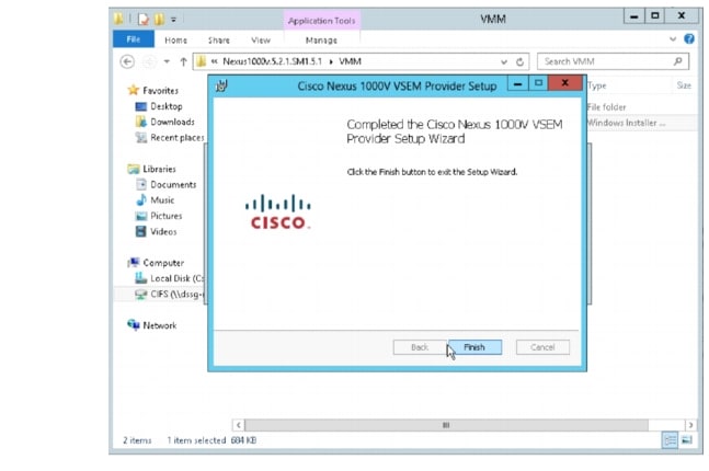
b. ![]() Follow the prompts as shown in Figure 3-2, Figure 3-3, and Figure 3-4 until the install is complete.
Follow the prompts as shown in Figure 3-2, Figure 3-3, and Figure 3-4 until the install is complete.
Figure 3-2 Run the MSI Installer
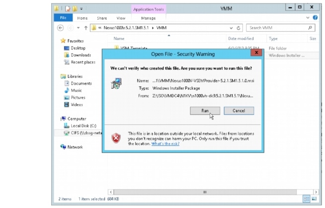
Figure 3-3 Read and Accept the License Agreement
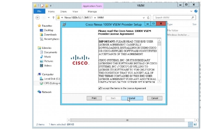
Figure 3-4 Select Finish when the Installer completes
Step 3 ![]() Verify that VSEM Provider is installed properly.
Verify that VSEM Provider is installed properly.
Go to Settings > Configuration Providers. Confirm that Cisco Systems Nexus 1000V is listed as a Configuration Provider.
Figure 3-5 Cisco VSEM Provider installed

Step 4 ![]() Copy VEM MSI to SCVMM repository.
Copy VEM MSI to SCVMM repository.
The VEM is an MSI file that must be placed in the following location on the SCVMM server: ALLUSERSPROFILE%\Switch Extension Drivers, for example, C:\ProgramData\Switch Extension Drivers. SCVMM uses the MSI file during the Add host operation to install VEM code on the host.
Note ![]() Do not install VEM code on the SCVMM server; only copy the file to the specified location.
Do not install VEM code on the SCVMM server; only copy the file to the specified location.
Step 5 ![]() Add VSEM (Connect SCVMM to VSM).
Add VSEM (Connect SCVMM to VSM).
The following procedures add the VSEM that was just installed. This step is required to connect SCVMM to the VSM in Hyper-V.
In these steps, the login account and the MGMT IP address configured in the VSM are needed to establish the communication between SCVMM and the VSM. Once the VSEM is added, the configuration that was created in the CLI of the VSM can be pulled in the SCVMM.
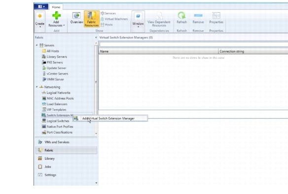
a. ![]() Right-click Switch Extension Manager and select Virtual Switch Extension Manager..
Right-click Switch Extension Manager and select Virtual Switch Extension Manager..
Figure 3-6 Add VSEM
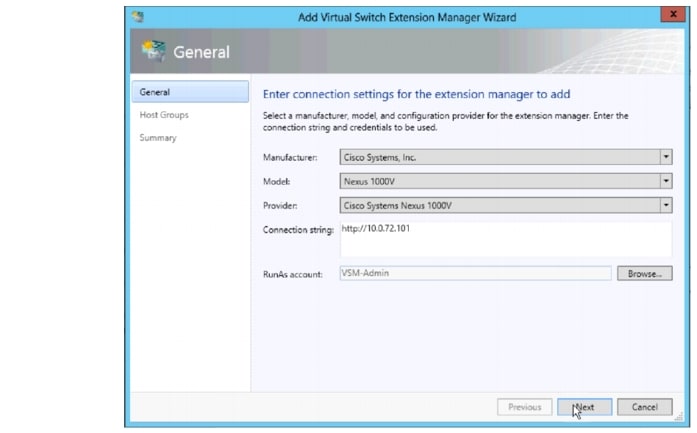
b. ![]() Add the Connection string and select Run As Account.
Add the Connection string and select Run As Account.
10.0.72.101 is the IP address of the VSM created on the Nexus 1110x.
The created account uses the login credentials required to log in to VSM.
Figure 3-7 Add VSEM Wizard
Refer to Installing Cisco Nexus 1000v for Microsoft Hyper-V for more information about creating a Run As Account.
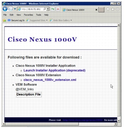
c. ![]() Verify that no additional configuration, such as proxy, is required.
Verify that no additional configuration, such as proxy, is required.
Open a browser and test the connection to the VSM. Browse to http://<VSM IP Address>.
Output similar to Figure 3-5 should be seen:
Figure 3-8 Browse to VSM
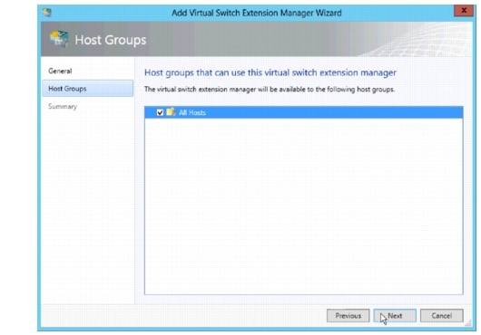
d. ![]() Select the host group to which the VSEM is available.
Select the host group to which the VSEM is available.
Figure 3-9 Add VSEM Wizard All Hosts
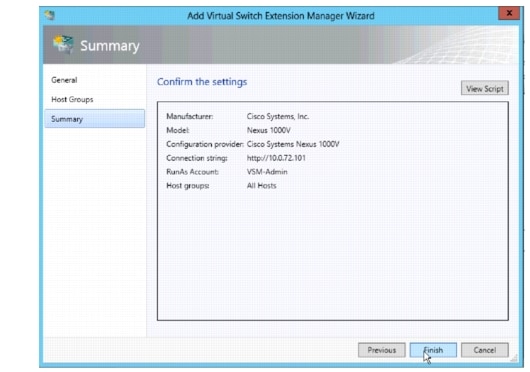
e. ![]() Confirm the VSEM settings and click Finish.
Confirm the VSEM settings and click Finish.
Figure 3-10 Add VSEM Wizard Confirm Settings
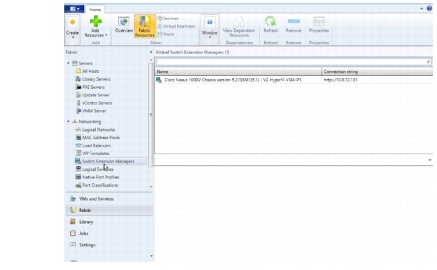
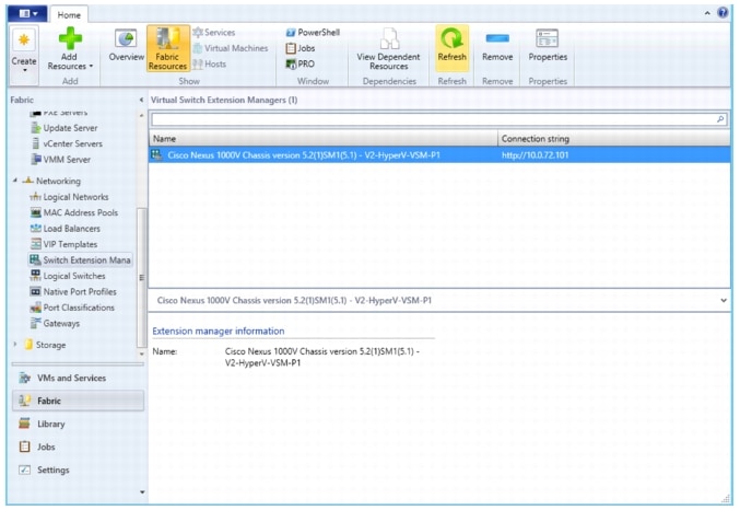
f. ![]() Verify that Virtual Switch Extension Manager is installed.
Verify that Virtual Switch Extension Manager is installed.
Figure 3-11 Verify VSEM is installed
Step 6 ![]() Create Logical Switch in SCVMM.
Create Logical Switch in SCVMM.
After VSEM is added (Step 5), do the following:
1. ![]() Create a logical switch on VMM using VSEM.
Create a logical switch on VMM using VSEM.
2. ![]() Define extensions and port profiles for the logical switch.
Define extensions and port profiles for the logical switch.
3. ![]() Create classifications containing the native port profile and a port profile for each extension.
Create classifications containing the native port profile and a port profile for each extension.
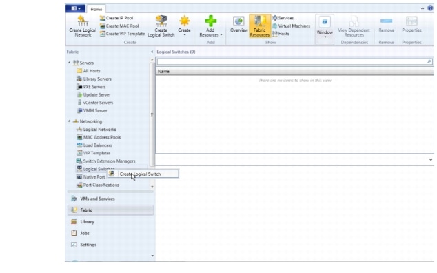
a. ![]() Right-click Logical Switch and select Create Logical Switch.
Right-click Logical Switch and select Create Logical Switch.
Figure 3-12 Create Logical Switch
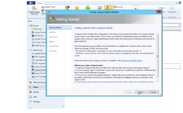
b. ![]() Read the text and click Next.
Read the text and click Next.
Figure 3-13 Create Logical Switch Getting Started
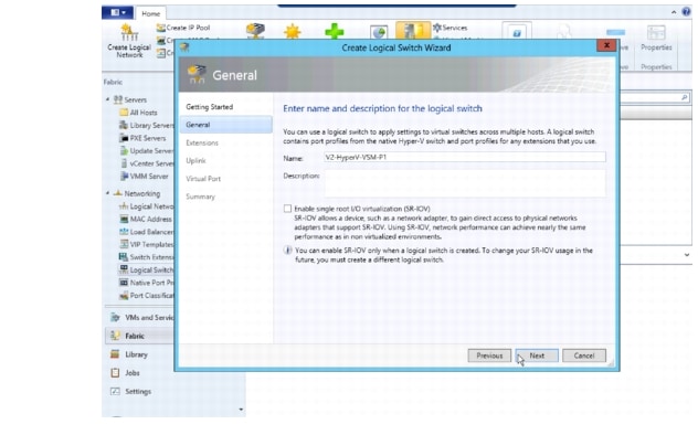
c. ![]() Name the logical switch.
Name the logical switch.
In this case, the hostname of the VSM was used. Use defaults for SR-IOV.
Figure 3-14 Create Logical Switch Name
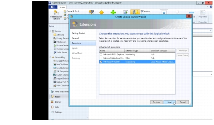
d. ![]() Check the previously configured VSEM (V2-HyperV-VSM-P1) and click Next.
Check the previously configured VSEM (V2-HyperV-VSM-P1) and click Next.
The VSEM has the following attributes:
Extension type: Forwarding
Extension Manager: Cisco Nexus 1000V Chassis
Only one virtual switch extension can be selected.
Figure 3-15 Create Logical Switch Select VSEM
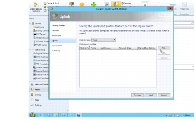
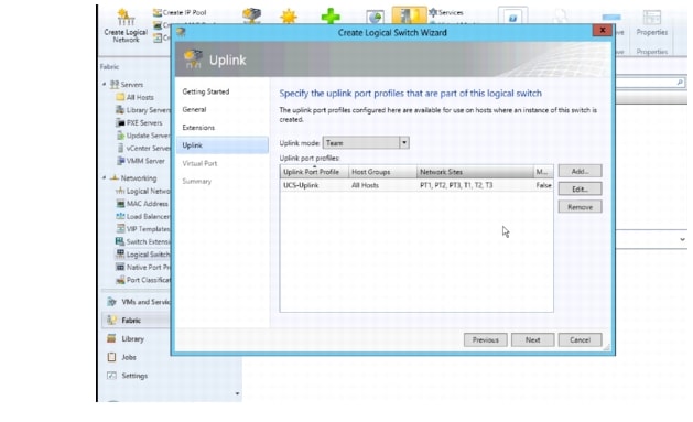
e. ![]() Select Team in the uplink mode field and click Add to add the uplink port profile.
Select Team in the uplink mode field and click Add to add the uplink port profile.
Note ![]() The mode should always be Team, whether using a single uplink or multiple uplinks.
The mode should always be Team, whether using a single uplink or multiple uplinks.
Figure 3-16 Create Logical Switch Select Add Uplink
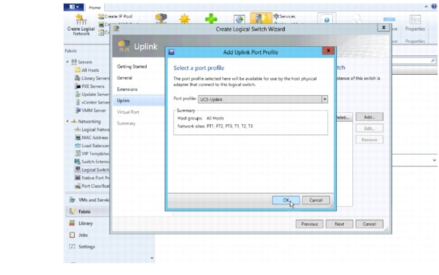
f. ![]() Select the uplink port profile and click OK.
Select the uplink port profile and click OK.
Figure 3-17 Add Uplink Port Profile
g. ![]() Confirm the uplink port profile settings and click Next.
Confirm the uplink port profile settings and click Next.
By default, the host group All Hosts is created in Hyper-V. The network sites PT1, PT2, PT3, T1, T2 and T3 were created during Nexus 1000V CLI configuration.
Figure 3-18 Create Logical Switch Note Host Groups and the Network site
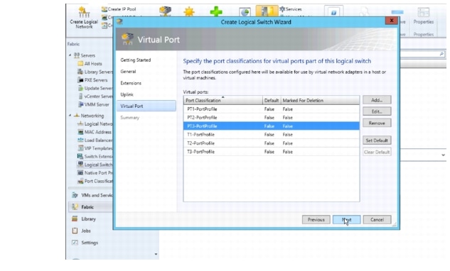
h. ![]() Specify the Port Classifications and click Next.
Specify the Port Classifications and click Next.
Port Classifications must be created in SCVMM and linked to port-profiles created in the VSM. The port-profiles were created previously in the "Nexus 1000V Switch for Microsoft Hyper-V VSM CLI Configuration" section; one port classification per port profile was created. When adding VMs to the logical switch, the port classification and VM network are selected when configuring network adapters (see VM Deployment).
Refer to Creating Logical Switch in SCVMM in Installing Cisco Nexus 1000V for Microsoft Hyper-V for additional guidance for creating port classifications.
Figure 3-19 Create Logical Switch Specify the Port Classifications
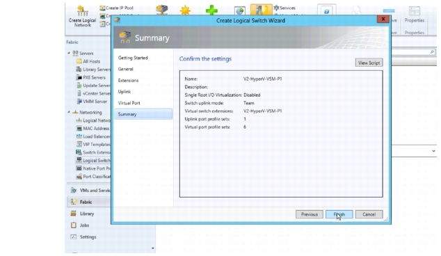
i. ![]() In the Summary panel, confirm the settings and click Finish to create the logical switch.
In the Summary panel, confirm the settings and click Finish to create the logical switch.
Figure 3-20 Create Logical Switch Specify Confirm Settings
j. ![]() Manually refresh the VSEM.
Manually refresh the VSEM.
After the Nexus 1000V logical switch is created, manually refresh VSEM to force the updates to appear in SCVMM.
Figure 3-21 Manual Refresh of the VSEM
Step 7 ![]() Add VEMs (Hosts) to the Nexus 1000V.
Add VEMs (Hosts) to the Nexus 1000V.
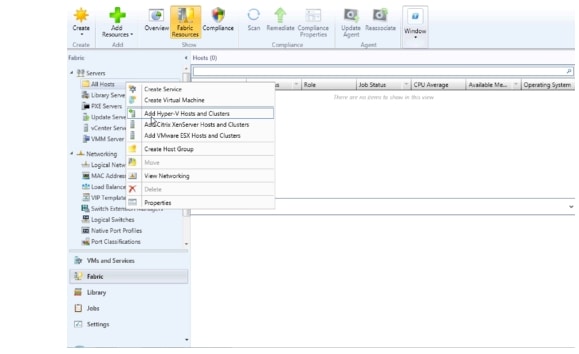
a. ![]() Right-click All Hosts and select Add Hyper-V Hosts and Clusters ..
Right-click All Hosts and select Add Hyper-V Hosts and Clusters ..
Figure 3-22 Add Hyper-V Hosts
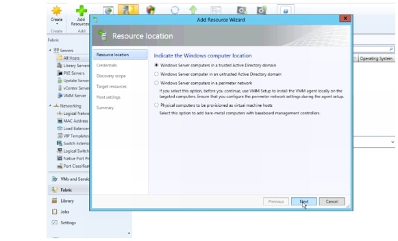
b. ![]() Select the appropriate computer location and click Next.
Select the appropriate computer location and click Next.
All hosts in the test bed were in a trusted Active Directory domain.
Figure 3-23 Add Hyper-V Hosts Windows Computer Location
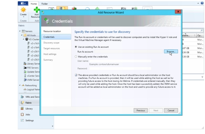
c. ![]() Click Browse to see a list of Run As Accounts.
Click Browse to see a list of Run As Accounts.
Figure 3-24 Add Hyper-V Hosts Specify Credentials
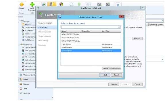
d. ![]() Select the Run As account created during the Hyper-V install.
Select the Run As account created during the Hyper-V install.
The account is different than the Run As account used to install VSEM. The scvmmadmin account was created in Active Directory and is a domain administrator account for the local domain.
See the "Microsoft Windows Server 2012 Installation" section on page 2-6 for more information about the scvmmadmin account.
Figure 3-25 Add Hyper-V Hosts Select Run As Account
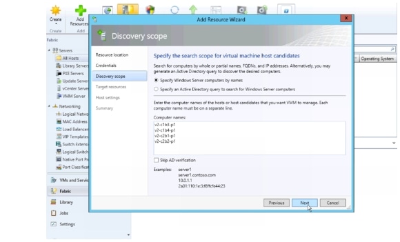
e. ![]() Enter the hostname of each host to add as a VEM and click Next.
Enter the hostname of each host to add as a VEM and click Next.
Figure 3-26 Add Hyper-V Hosts Enter Hostnames
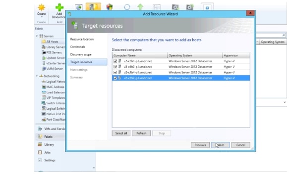
f. ![]() After hosts are discovered, select each host to add and click Next.
After hosts are discovered, select each host to add and click Next.
Figure 3-27 Add Hyper-V Hosts Select the Hosts
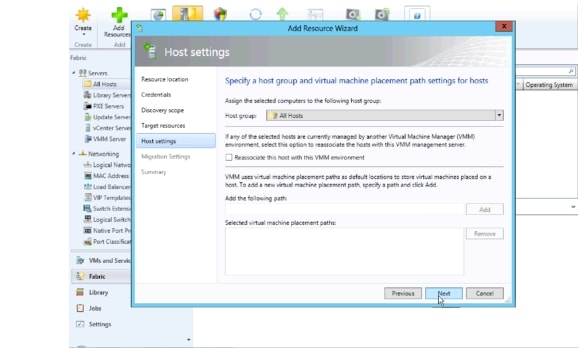
g. ![]() Assign hosts to a host groups.
Assign hosts to a host groups.
Leave Reassociate this host with the VMM environment unchecked and click Next.
Figure 3-28 Add Hyper-V Hosts Assign the Host Group
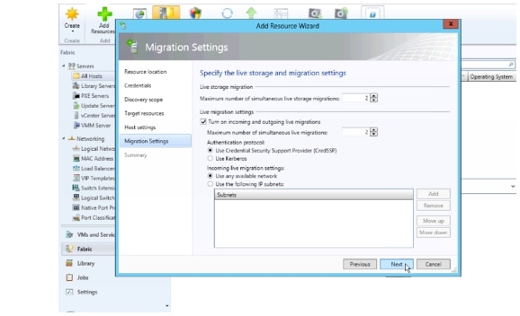
h. ![]() Enable Live Migration and click Next.
Enable Live Migration and click Next.
Figure 3-29 Add Hyper-V Hosts Enable Live Migration
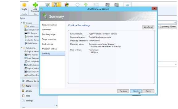
i. ![]() Confirm the Settings and click Finish.
Confirm the Settings and click Finish.
Figure 3-30 Add Hyper-V Hosts Confirm Settings
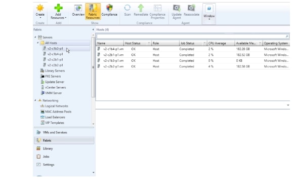
j. ![]() Verify All Hosts are seen in the All Hosts group.
Verify All Hosts are seen in the All Hosts group.
Figure 3-31 Add Hyper-V Hosts Verify All Hosts
Step 8 ![]() Add Each Host to Logical switch.
Add Each Host to Logical switch.
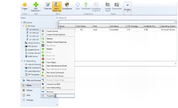
a. ![]() Right-click the host to be added and select Properties.
Right-click the host to be added and select Properties.
Figure 3-32 Host Properties
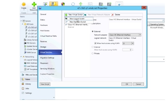
b. ![]() Add New Logical Switch.
Add New Logical Switch.
In the Host Properties > Virtual Switches window, select New Virtual Switch and New Logical Switch to add the host to the Nexus 1000V.
As seen in Figure 3-33, a standard External switch was already created for management. In Hyper-V, multiple switches can exist on the host.
Figure 3-33 Host Properties New Logical Switch
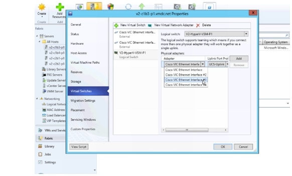
c. ![]() Add physical adapters to the logical switch team.
Add physical adapters to the logical switch team.
There are two adapters, VIC Ethernet interface 3 and VIC Ethernet interface 4 that will be used on each host. Add these to the logical switch.
Figure 3-34 Host Properties Add Physical Adapter 1
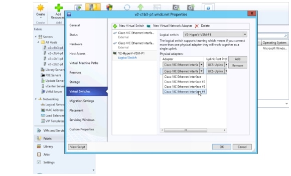
Add the second physical adapter 2 and hit OK.
Figure 3-35 Host Properties Add Physical Adapter 2
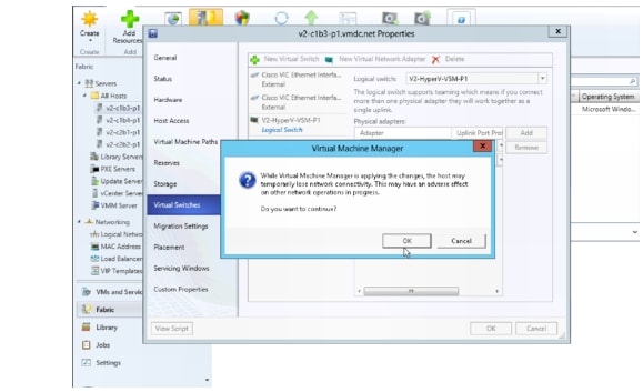
d. ![]() Click OK to continue to add host to the logical switch.
Click OK to continue to add host to the logical switch.
Figure 3-36 Host Properties Continue to Add Host to Logical Switch
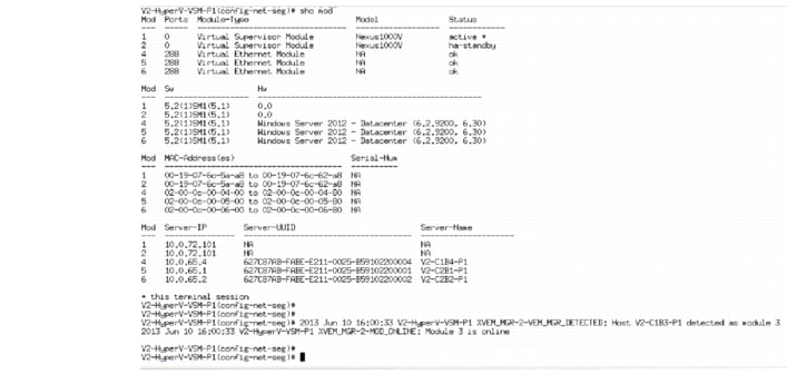
e. ![]() Verify that the VEM is installed on the VSM.
Verify that the VEM is installed on the VSM.
Figure 3-37 shows the output seen on the VSM when the VEM is added to the Logical switch.
Figure 3-37 Host added as a VEM
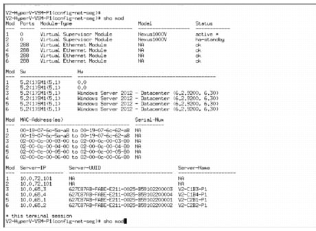
f. ![]() After all hosts were added to the logical switch, they are seen as VEMs in the VSM. Execute show module on the VSM to verify these hosts are seen as VEMs.
After all hosts were added to the logical switch, they are seen as VEMs in the VSM. Execute show module on the VSM to verify these hosts are seen as VEMs.
Figure 3-38 All Host Added as a VEM
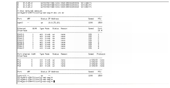
g. ![]() Verify interfaces are added to Logical Switch.
Verify interfaces are added to Logical Switch.
Because each host has two Cisco VIC Ethernet interfaces, two Ethernet interfaces per host are seen, along the port-channel interfaces.
These are:
Eth3/1
Eth3/2
Eth4/1
Eth4/2
Eth5/1
Eth5/2
Eth6/1
Eth6/2
Po1
Po2
Po3
Po4
These interfaces and port-channels can get verified by executing show interface brief on the VSM:
Figure 3-39 Show Interface Brief
Step 9 ![]() VM Network Creation.
VM Network Creation.
After the Nexus 1000V Switch for Microsoft Hyper-V Logical switch has been installed, the VM Networks can get created.
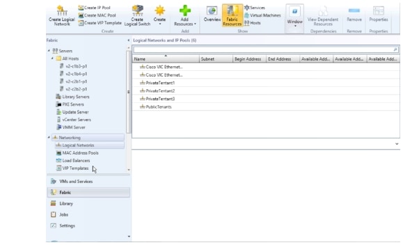
a. ![]() Verify the Logical Networks created on the N1000V are seen in Hyper-V.
Verify the Logical Networks created on the N1000V are seen in Hyper-V.
Figure 3-40 Logical Networks
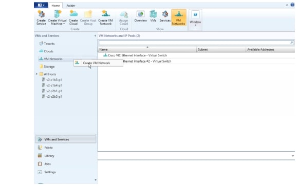
b. ![]() Right-click VM Network and select Create VM Network.
Right-click VM Network and select Create VM Network.
Figure 3-41 Create VM Network
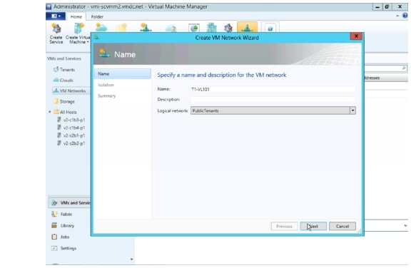
c. ![]() Create the VM network name and select the logical network.
Create the VM network name and select the logical network.
Figure 3-42 Create VM Network Name
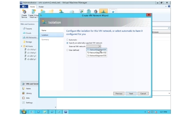
d. ![]() Select the network segment.
Select the network segment.
Figure 3-43 Select Network Segment
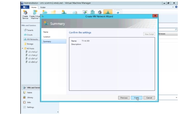
e. ![]() Confirm the VM network settings.
Confirm the VM network settings.
Figure 3-44 Confirm VM Network Settings
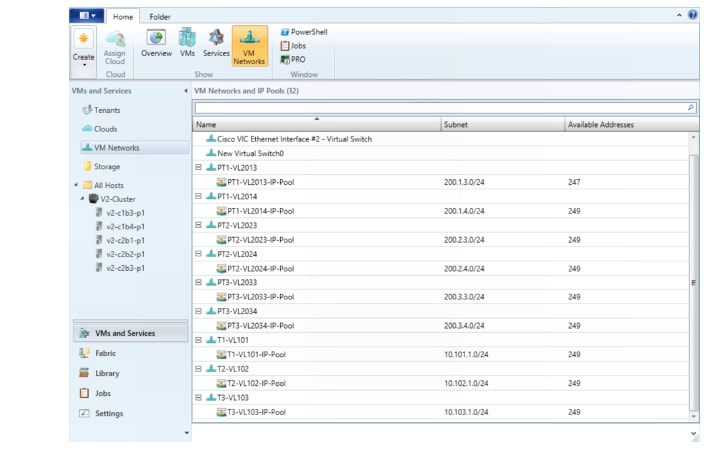
f. ![]() Follow the same steps to create the remaining VM Networks.
Follow the same steps to create the remaining VM Networks.
Figure 3-45 All VM Networks
g. ![]() Verify the network segment are now a "member-of" the correct VM Networks. This line of the configuration is automatically added to the CLI as noted Create Network Segments..
Verify the network segment are now a "member-of" the correct VM Networks. This line of the configuration is automatically added to the CLI as noted Create Network Segments..
nsm network segment T1-NetworkSegment101
member-of vmnetwork T1-NetworkSegment101
member-of network segment pool T1
switchport access vlan 101
ip pool import template T1-VL101-IP-Pool
publish network segment
switchport mode access
At this point, the logical switch, including VSM and VEMs, is installed. VMs can now be added to the logical switch.
Deployment Guidelines
1. ![]() Manually refresh the VSEM. Hyper-V performs a periodic refresh every 30 minutes; changes in the Nexus 1000V are not automatically updated in Hyper-V. Manually refresh the VSEM to force updates to show up in SCVMM.
Manually refresh the VSEM. Hyper-V performs a periodic refresh every 30 minutes; changes in the Nexus 1000V are not automatically updated in Hyper-V. Manually refresh the VSEM to force updates to show up in SCVMM.
2. ![]() Manually remove NetSwitchTeam. If a host is deleted from SCVMM, NetSwitchTeam is not removed from the host.
Manually remove NetSwitchTeam. If a host is deleted from SCVMM, NetSwitchTeam is not removed from the host.
If hosts are removed and added again, the hosts is not added to the logical switch because NetSwitchTeam still exists on the hosts.
This error is seen in the Jobs section:
Error (25238)
Creating the adapter team failed with error An internal error has occurred trying to contact the v2-c1b4-p1.vmdc.net server.
WinRM: URL: [http://v2-c1b4-p1.vmdc.net:5985], Verb: [GET], Resource: [http://schemas.microsoft.com/wbem/wsman/1/wmi/root/scvmm/ErrorInfo?ID=1001]
Check that WS-Management service is installed and running on server v2-c1b4-p1.vmdc.net. For more information use the command "winrm helpmsg hresult". If v2-c1b4-p1.vmdc.net is a host/library/update server or a PXE server role then ensure that VMM agent is installed and running. Recommended Action
ensure the team is functioning correctly and retry the operation
To clear this condition, open Windows PowerShell and do the following:
PS C:\Users\Administrator.VMDC> Get-NetSwitchTeam *
Name : V2-HyperV-VSM-P12b352411-1eff-4e95-bc84-9f0fb5a339a4
Members : {Ethernet 5, Ethernet 4}
PS C:\Users\Administrator.VMDC> Get-NetSwitchTeam | Remove-NetSwitchTeam
After the obsolete NetSwitchTeam is removed, the host can be added to the Logical switch.
3. ![]() Verify that hosts ports show up in VSM. In UCSM, each host had two MGMT and two DATA vNICs. The DATA vNICs were used for NetSwitchTeam. On one or two occasions, when a host was added to the Nexus 1000V logical switch, only one interface showed up in the VSM for that VEM, even though both interfaces were selected. The procedure to add the host to the Nexus 1000V had to be repeated, and the interface that did not show up had to be added to the newly created Nexus 1000V connection.
Verify that hosts ports show up in VSM. In UCSM, each host had two MGMT and two DATA vNICs. The DATA vNICs were used for NetSwitchTeam. On one or two occasions, when a host was added to the Nexus 1000V logical switch, only one interface showed up in the VSM for that VEM, even though both interfaces were selected. The procedure to add the host to the Nexus 1000V had to be repeated, and the interface that did not show up had to be added to the newly created Nexus 1000V connection.
This can be verified by logging into the VSM and looking at the output from show interface brief. Look for the VEM and the ports. A show port-channel summary should shows those ports added to the port-channel.
4. ![]() Close and reopen SCVMM. On occasion, odd behavior was seen, such as hosts not responding to messages. Connecting to hosts using Remote Desktop Protocol (RDP) showed that the hosts were in the correct state. Closing and reopening the SCVMM app cleared this state. This is most likely a winrm issue that needs further investigation when it happens again.
Close and reopen SCVMM. On occasion, odd behavior was seen, such as hosts not responding to messages. Connecting to hosts using Remote Desktop Protocol (RDP) showed that the hosts were in the correct state. Closing and reopening the SCVMM app cleared this state. This is most likely a winrm issue that needs further investigation when it happens again.
5. ![]() Create a Gold Template for SCVMM. After three to four weeks, SCVMM became unstable. A new SCVMM was created, and a Gold Template was generated from that VM, in case the instability recurs.
Create a Gold Template for SCVMM. After three to four weeks, SCVMM became unstable. A new SCVMM was created, and a Gold Template was generated from that VM, in case the instability recurs.
6. ![]() Refer to Cisco Nexus 1000V for Microsoft Hyper-V Installation Guide, Release 5.2(1)SM1(5.1) for information about creating the Nexus 1000V logical switch in Hyper-V SCVMM.
Refer to Cisco Nexus 1000V for Microsoft Hyper-V Installation Guide, Release 5.2(1)SM1(5.1) for information about creating the Nexus 1000V logical switch in Hyper-V SCVMM.
Adding VMs to Nexus V Switch for Hyper-V Logical Switch
This section shows the process for adding Virtual Machines to the Nexus 1000V Switch for Microsoft Hyper-V Logical switch.
Step 1 ![]() Go to the VM Properties page.
Go to the VM Properties page.
Right-click the VM and select Properties.
Step 2 ![]() Select Hardware Configuration and select the adapter to add to the logical switch.
Select Hardware Configuration and select the adapter to add to the logical switch.
There are two adapters in the test VMs. One connects to the Microsoft external switch for Management and the other connects to the Nexus 1000V.
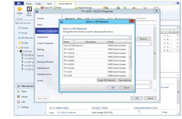
Step 3 ![]() Select the VM network.
Select the VM network.
On the network adapter properties page, click Browse to see a list of available VM networks.
Figure 3-46 Select a VM Network
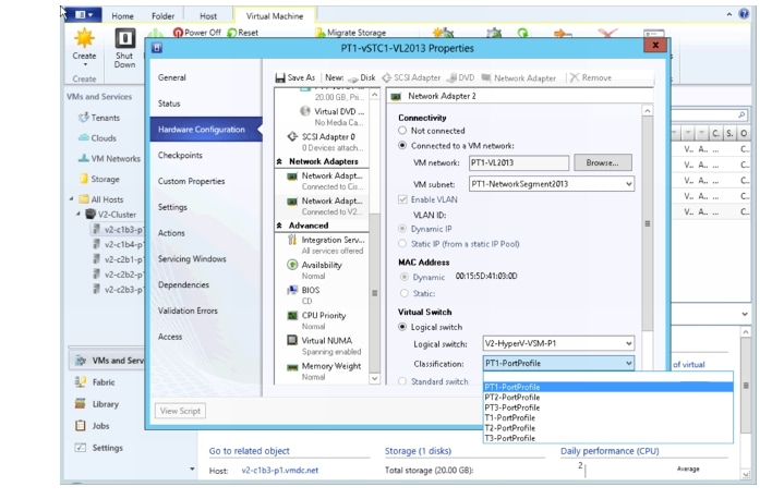
Step 4 ![]() Select the classification.
Select the classification.
After selecting the VM network, click the Classification drop-down and select the classification profile.
Figure 3-47 Select Classification
Step 5 ![]() After selecting the classification, click OK.
After selecting the classification, click OK.
Step 6 ![]() Verify the Virtual Machine has been deployed by issuing a "show interface virtual" from the CLI of the VSM:
Verify the Virtual Machine has been deployed by issuing a "show interface virtual" from the CLI of the VSM:
V2-HyperV-VSM-P1# show interface virtual
-------------------------------------------------------------------------------
Port Adapter Owner Mod Host
-------------------------------------------------------------------------------
Veth1 Net Adapter PT1-vSTC1-VL2013 3 V2-C1B3-P1
Veth2 Net Adapter PT1-vSTC1-VL2014 3 V2-C1B3-P1
Veth3 Net Adapter PT3-vSTC1-VL2033 3 V2-C1B3-P1
Veth4 Net Adapter T1-vSTC1-VL101 3 V2-C1B3-P1
Veth5 Net Adapter PT2-vSTC1-VL2023 4 V2-C1B4-P1
Veth6 Net Adapter PT2-vSTC1-VL2024 4 V2-C1B4-P1
Veth7 Net Adapter PT3-vSTC1-VL2034 4 V2-C1B4-P1
Veth8 Net Adapter T2-vSTC1-VL102 4 V2-C1B4-P1
Veth9 Net Adapter PT1-vSTC2-VL2013 5 V2-C2B1-P1
Veth10 Net Adapter PT1-vSTC2-VL2014 5 V2-C2B1-P1
Veth11 Net Adapter PT3-vSTC2-VL2033 5 V2-C2B1-P1
Veth12 Net Adapter T3-vSTC1-VL103 5 V2-C2B1-P1
Veth13 Net Adapter PT2-vSTC2-VL2023 6 V2-C2B2-P1
Veth14 Net Adapter PT2-vSTC2-VL2024 6 V2-C2B2-P1
Veth15 Net Adapter PT3-vSTC2-VL2034 6 V2-C2B2-P1
Veth16 Net Adapter LM-Windows Server 2012 -01 4 V2-C1B4-P1
Veth17 Net Adapter LM-Win2008-02 4 V2-C1B4-P1
Deployment Guidelines
1. ![]() Select the correct interfaces when adding network adapters. In UCSM, each host has two MGMT and two DATA vNICs. From the Windows OS perspective, four VIC interfaces are presented. Ensure that the correct interfaces are selected when adding the hosts to virtual switches. Check the MAC addresses.
Select the correct interfaces when adding network adapters. In UCSM, each host has two MGMT and two DATA vNICs. From the Windows OS perspective, four VIC interfaces are presented. Ensure that the correct interfaces are selected when adding the hosts to virtual switches. Check the MAC addresses.
2. ![]() Refer to Connecting VMs to Logical Switch in Cisco Nexus 1000v for Microsoft Hyper-V Installation Guide, Release 5.2(1)SM1(5.1) for more information.
Refer to Connecting VMs to Logical Switch in Cisco Nexus 1000v for Microsoft Hyper-V Installation Guide, Release 5.2(1)SM1(5.1) for more information.
 Feedback