- Cisco Service Ready Architecture for Schools Solution Overview
- Service Ready Architecture for Schools�A Framework for Education
- Network Foundation Design
- Security Design
- Wireless LAN Design
- Context-Aware Services Design
- Unified Communications Design
- Digital Media and Video Surveillance Design
- Access Layer Security Design
- School Site Design
- District Office Design
District Office Design
There are four main differences in the district office design:
•![]() The use of the Supervisor 6—The Supervisor 6 supports hierarchical QoS.
The use of the Supervisor 6—The Supervisor 6 supports hierarchical QoS.
•![]() The Metro Ethernet Switch Connection—The aggregation and QoS policy enforcement point for the Metro Ethernet WAN connection to the schools
The Metro Ethernet Switch Connection—The aggregation and QoS policy enforcement point for the Metro Ethernet WAN connection to the schools
•![]() The Services Block Switch Connection—The district office "mini-Data Center" for the management and services servers for the district and the schools
The Services Block Switch Connection—The district office "mini-Data Center" for the management and services servers for the district and the schools
•![]() The ASA Firewall Connection—The firewall connection to the Internet
The ASA Firewall Connection—The firewall connection to the Internet
Figure 11-1 shows a schematic of the district office network. Aside from providing core/distribution services to the access switches, the Cisco 4500 Modular switch in the district office connects the school WAN to the district office, the services such as Internet access and the Services Block of the SRA.
Figure 11-1 District Office Partial Schematic

Metro Ethernet Connection Configuration
Table 11-1 shows an example of the port-channel configuration on the core/distribution 4500 Modular switch and the 3750 Metro Ethernet switch. This is a Layer-3 connection where both the core/distribution switch and the Metro Ethernet switch are part of the same EIGRP AS. The most significant difference in this configuration from the School design using the 4500 Modular switch is the difference in the QoS configuration on the 4500 interface; this is primarily due to the district office using hierarchical QoS features of a Supervisor 6 module, rather than the Supervisor 5 used in the School SRA.
ASA Connection
The ASA firewall connection to the 4500 Modular switch is fundamentally different from the other network device connections to this switch—it uses the redundant interface features of the ASA. The ASA redundant interface is a logical interface that pairs two physical interfaces, called active and standby interfaces. Under normal operation, the active interface is the only one passing traffic. The active interface uses the IP address defined at the redundant interface, and the MAC address of the first physical interface associated with the redundant interface. When the active interface fails, the standby interface becomes active and starts passing traffic. The same IP address and MAC address are maintained so that traffic is not disrupted. See Table 11-2.
Services Block Connection
The Services Block supports the centralized servers and services for the district. The Cisco 4500 Modular switch connection to the Services Block switch uses EtherChannel, but in this case the connection between the switches is a Layer-3 connection, allowing the services block switch to keep its VLANs from stack is fundamentally the same as an access switch connection, with different VLANs. Table 11-3 provides sample configurations for the Cisco 4500 Modular switch and the Services Block switch.
Core/Distribution Virtual Interfaces
The following is an example configuration of the Switch Virtual Interfaces configured on the core/distribution 4500 modular switch. This SVIs are trunked to the access switches as required, and access to the VLANs are controlled by the switchport trunk allowed vlan command applied on the port channels. The same basic configuration is used for the Server Switch.
interface Vlan101
description Connected to cr24_2960_Dept_1_VLAN
dampening
ip address 10.125.1.1 255.255.255.128
ip helper-address 10.125.31.2
no ip redirects
no ip unreachables
ip pim sparse-mode
load-interval 30
!
interface Vlan102
description Connected to cr24_2960_Dept_2_VLAN
dampening
ip address 10.125.1.129 255.255.255.128
ip helper-address 10.125.31.2
no ip redirects
no ip unreachables
ip pim sparse-mode
load-interval 30
!
...
interface Vlan110
description Connected to cr24_2960_Dept_10_VLAN
dampening
ip address 10.125.5.129 255.255.255.128
ip helper-address 10.125.31.2
no ip redirects
no ip unreachables
ip pim sparse-mode
load-interval 30
Table 11-4 provides examples of the port-channel configuration on core/distribution 4500 modular switch and an access switch. A similar configuration would be applied to each access switch connection with the same or different VLANs as required. From an IP routing or services level there is no requirement to span the same VLAN to multiple switches, but if there is a requirement to support legacy protocols such as AppleTalk at the school these AppleTalk VLANs can be easily spanned to different access switches as required.
WLC Connection
The WLC Connection to the Core/Distribution Stack is fundamentally the same as an Access Switch connection, with different VLANs, and the exception of using a different QoS trust mode, where the CoS values from the WLC, are trusted. Figure 7 shows an example of the configuration.
Interface Port-channel12
description Connected to WLC-SS2
switchport trunk encapsulation dot1q
switchport trunk native vlan 802
switchport trunk allowed vlan 111-120
switchport mode trunk
load-interval 30
carrier-delay msec 0
ip dhcp snooping trust
interface GigabitEthernet1/0/48
description Connected to WLC-SS2
switchport trunk encapsulation dot1q
switchport trunk native vlan 802
switchport trunk allowed vlan 110-120
switchport mode trunk
load-interval 30
carrier-delay msec 0
srr-queue bandwidth share 1 30 35 5
priority-queue out
udld port
mls qos trust cos
channel-group 11 mode active
spanning-tree guard root
!
interface GigabitEthernet3/0/48
description Connected to WLC-SS2
switchport trunk encapsulation dot1q
switchport trunk native vlan 802
switchport trunk allowed vlan 110-110,
switchport mode trunk
load-interval 30
carrier-delay msec 0
srr-queue bandwidth share 1 30 35 5
priority-queue out
udld port
mls qos trust cos
channel-group 11 mode active
spanning-tree guard root
NAC CAS Connection
The NAC CAS connection to the core/distribution switch. This is not an EtherChannel connection, but two switch ports are consumed. The two ports consist of a untrusted port for connecting client VLANs to the CAS prior to them completing the NAC process, and a trusted port that connects the NAS to the client VLANs used once clients have successfully completed the NAC process. The two, trusted and untrusted, ports are required even if OOB NAC is used, as the CAS requires access to the trusted VLANs during the NAC process. The following is an example of the configuration.
interface GigabitEthernet 3/9
description NAC Trusted Eth0
switchport trunk encapsulation dot1q
switchport trunk allowed vlan 48,57,62
switchport mode trunk
spanning-tree portfast trunk
!
interface GigabitEthernet 4/9
description NAC Untrusted Eth1
switchport trunk encapsulation dot1q
switchport trunk allowed vlan 61,248,257
switchport mode trunk
spanning-tree portfast trunk
SRST Connection
The SRST connection to the core/distribution is another EtherChannel connection. The differences between the SRST connection and the access switch connections are that a trunk connection is not required, and that the SRST interfaces are router interfaces, requiring a slightly different connection. Table 11-5 provides an example of the configuration.
NTP
The use of Network Time Protocol (NTP) to synchronize the clocks of network devices is a well established best practice, is fundamental for the analysis of logs/events and security, but might not warrant a mention in a design guide that is focused upon introducing new designs and practices to support new services in the network.
Given that a number of key components (for example, CUWN and Cisco NAC) of the Schools SRA rely upon or benefit from time synchronization, it was decided to include a short discussion on Time Synchronization as part of the Schools SRA.
The preferred mechanism for time synchronization in the network is NTP (other systems may use their own time synchronization mechanism) and this network NTP discussion is not proposed as a the design to synchronize all devices (hosts) in the network, its goal is synchronization of the network components of the Schools SRA. At the same time, whatever alternative times synchronization systems used in other parts of the network need to have agreement on the time, and should have a common time source at the beginning of their timing hierarchy. This will allow sufficient synchronization between hosts and network devices for the solutions deployed in the SRA.
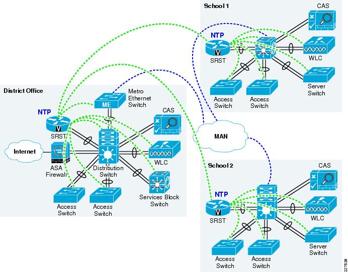
The Schools SRA network has a hierarchy based upon the district office, as hub, and the schools as spokes. The NTP hierarchy should be the same, with the highest stratum NTP server located at the district office serving as the time reference for the district network. In order to spread the load, a hierarchy of NTP servers is used. The district office NTP server acting as the server for the district office network devices, and for the NTP server at each school, and the NTP Server for each school will act as the NTP server for network devices in that school.
The preferred network device to act as the NTP server in the schools SRA is the ISR router at each site. The ISR is the preferred device as routers have a greater CPU capacity than switches used in the Schools SRA due to many of the general purpose task that a router may be required it perform in CPU, compared to switches that have been more optimized to perform their more limited number of tasks in ASIC.
Figure 11-2 shows a schematic of the NTP hierarchy in the school district.
For more information upon NTP refer to the Network Time Protocol: Best Practices White Paper at the following URL:
http://www.cisco.com/en/US/tech/tk869/tk769/technologies_white_paper09186a0080117070.shtml
Figure 11-2 NTP School District Hierarchy
When creating the NTP configuration care should be taken to protect the NTP system.
The NTP associations should be limited, and controlled by an access list, to protect against DoS attacks. The NTP system should also use NTP authentication, where possible, to protected against spoofing attacks.
 Feedback