Media Optimization with ICE Enablement in Cisco Enterprise Collaboration Preferred Architecture 12.5
Available Languages
Table of Contents
Media Optimization with ICE Enablement in Cisco Enterprise Collaboration Preferred Architecture 12.5
Collaboration Edge Architecture
Recommendations and Design Considerations
Collaboration Edge Deployment Overview
Bandwidth Management Architecture
Recommendations and Design Considerations
Bandwidth Management Deployment Overview
Media Optimization with ICE Enablement in Cisco Enterprise Collaboration Preferred Architecture 12.5
Introduction
This document presents an alternative design to the Preferred Architecture for Enterprise Collaboration 12.5. In particular, this document describes how to enable Interactive Connectivity Establishment (ICE) protocol for Mobile and Remote Access (MRA) endpoints in the Preferred Architecture. ICE makes use of Traversal Using Relay NAT (TURN) and Session Traversal Utilities for NAT (STUN) to optimize the media path of MRA calls. This document builds upon the information in the Preferred Architecture for Cisco Collaboration 12.x Enterprise On-Premises Deployments, CVD, and must be used in conjunction with that CVD guide. This document covers only the applicable design changes needed to enable ICE in the Preferred Architecture for Enterprise Collaboration 12.5.
Architecture Overview
This section describes the Interactive Connectivity Establishment (ICE) architecture and the ICE back-to-back user agent (B2BUA) transparency feature that has been implemented on Cisco Expressway.
ICE enablement for MRA endpoints is an optional feature new in Cisco Collaboration System Release (CSR) 12.5 It allows MRA endpoints to connect their media directly, peer-to-peer, instead of via the Expressway-C B2BUA, thus optimizing their media flow. This reduces delay, packet loss, and use of Expressway hardware resources as well as Internet bandwidth usage at the head-end where the Expressway pair for MRA is deployed.
To accomplish this more efficient direct media flow, the SIP architecture utilizes a client-server model for the signaling and a peer-to-peer model for media. In some cases, the peer-to-peer media traffic might be difficult to achieve. One reason is that endpoints involved in a call might support different codecs or different protocols. In this case the engagement of a media termination server such as a Media Termination Point (MTP) or a Session Border Controller (SBC) might be required. Another reason is that there might not be direct connectivity between two endpoints. This happens very often when the two endpoints are separated by one or more NAT/PAT (Network Address Translation / Port Address Translation) devices and firewalls because the firewalls might not allow media, which runs on top of UDP, to all possible destinations. Firewalls and NAT devices also might allow inbound UDP traffic only after outbound traffic is already sent.
In order to circumvent these problems, a series of UDP hole-punching techniques have been designed. One of these techniques is called Session Traversal Utilities for NAT (STUN), which is defined in RFC 5389 and works under specific NAT conditions. Using STUN, endpoints and clients can create and maintain UDP connections through one or many firewalls and NAT devices.
However, if the firewall does not even allow outbound UDP traffic or if it performs symmetric NAT (IP address and TCP/UDP ports are translated differently if different hosts are contacted by the same client), then STUN technology will not work. In this case the media might be handled by a central server using a protocol called Traversal Using Relays around NAT (TURN), defined in RFC 5766.
Interactive Connectivity Establishment (ICE), defined in RFC 8445, is a protocol that combines STUN and TURN. Using ICE, endpoints can determine if there is direct connectivity between them and will then apply the STUN hole-punching techniques to keep the firewall ports opened, thus allowing for both inbound and outbound media traffic. If direct media connectivity cannot be achieved, the endpoints will fall back to the TURN server and will send their UDP traffic centrally instead of going peer-to-peer.
In short, ICE is a protocol that has been designed to find the best media path between two network elements when the connection is traversing multiple firewalls and NAT devices. By reducing bandwidth overhead, ICE not only saves bandwidth for use by other traffic but also has another indirect benefit of overall improved audio and video quality due to the shortening of the media path, which alleviates the packet loss and delay that cause poor audio and video quality.
Figure 1 illustrates three media flows with a single Expressway pair for MRA deployed in a single site with direct Internet access:
1.![]() Standard media path — This is the traditional media path for MRA endpoints (without ICE enablement) located on the Internet. When the initial call between Bob and Alice takes place, the B2BUA on Expressway-C bridges the media legs between Bob to Alice.
Standard media path — This is the traditional media path for MRA endpoints (without ICE enablement) located on the Internet. When the initial call between Bob and Alice takes place, the B2BUA on Expressway-C bridges the media legs between Bob to Alice.
2.![]() Media through the TURN server — This is a media path for ICE-enabled endpoints that do not support direct media between one another for whatever reason. In this case the media is bridged between the TURN server and the MRA endpoints.
Media through the TURN server — This is a media path for ICE-enabled endpoints that do not support direct media between one another for whatever reason. In this case the media is bridged between the TURN server and the MRA endpoints.
3.![]() Peer-to-peer media — This is a media path for ICE-enabled endpoints where media is able to flow directly between the endpoints. This is the optimum path for media to flow, and it has the benefits of reducing delay, packet loss, use of Expressway hardware resources, and Internet bandwidth usage at the enterprise Expressway head-end.
Peer-to-peer media — This is a media path for ICE-enabled endpoints where media is able to flow directly between the endpoints. This is the optimum path for media to flow, and it has the benefits of reducing delay, packet loss, use of Expressway hardware resources, and Internet bandwidth usage at the enterprise Expressway head-end.
Figure 1 Media Flows in a Single-Site Expressway Pair Deployment for MRA
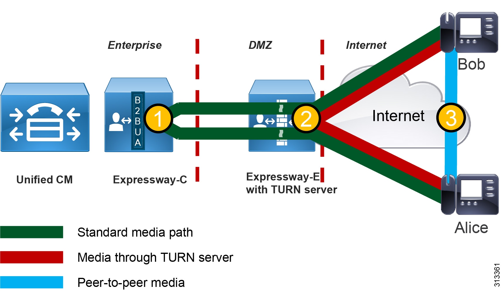
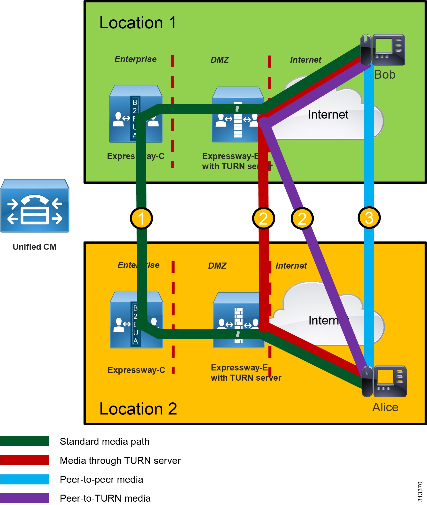
Figure 2 illustrates four media flows between Expressway pairs deployed in different sites, each with their own direct Internet access:
1.![]() Standard media path — This is the traditional media path for MRA endpoints (without ICE enablement) located on the Internet, where both endpoints are registered to Unified CM through different Expressway pairs attached to their own direct Internet access. When the initial call between Bob and Alice takes place, the B2BUA on Expressway-C bridges the media legs from Bob to Alice between Expressway-C's B2BUA, and vice versa.
Standard media path — This is the traditional media path for MRA endpoints (without ICE enablement) located on the Internet, where both endpoints are registered to Unified CM through different Expressway pairs attached to their own direct Internet access. When the initial call between Bob and Alice takes place, the B2BUA on Expressway-C bridges the media legs from Bob to Alice between Expressway-C's B2BUA, and vice versa.
2.![]() Media through the TURN server — There are two possible types of media paths for ICE-enabled endpoints that do not support direct media between one another for whatever reason. In this case the media is bridged between the MRA endpoints and either one or both TURN server(s) over their direct Internet access.
Media through the TURN server — There are two possible types of media paths for ICE-enabled endpoints that do not support direct media between one another for whatever reason. In this case the media is bridged between the MRA endpoints and either one or both TURN server(s) over their direct Internet access.
3.![]() Peer-to-peer media — This is a media path for ICE-enabled endpoints where media is able to flow directly between the endpoints. This is the optimum path for media to flow, and it has the benefits of reducing delay, packet loss, use of Expressway hardware resources, and Internet bandwidth usage at the enterprise Expressway head-end.
Peer-to-peer media — This is a media path for ICE-enabled endpoints where media is able to flow directly between the endpoints. This is the optimum path for media to flow, and it has the benefits of reducing delay, packet loss, use of Expressway hardware resources, and Internet bandwidth usage at the enterprise Expressway head-end.
Figure 2 Media Flows Between Expressway Pairs Deployed in Different Sites
Core Components
The core components of the ICE architecture with Mobile and Remote Access (MRA) are:
- Cisco Expressway-C and Expressway-E X12.5 or later release is required for Internet connectivity and firewall traversal.
- TURN server enabled on Expressway-E for TURN media relay
- Cisco IP Phone 8800 Series, 7800 Series, and/or other endpoints running CE firmware, enabled for MRA (For the minimum endpoint release that supports ICE, refer to the release notes for the endpoints.)
- Cisco Unified Communications Manager (Unified CM) 11.5 or later release.

Note![]() This document assumes you have deployed Cisco Unified CM 12.5, as is consistent with the Preferred Architecture for Enterprise Collaboration 12.5. Unified CM 12.5 is required if Jabber is deployed with ICE.
This document assumes you have deployed Cisco Unified CM 12.5, as is consistent with the Preferred Architecture for Enterprise Collaboration 12.5. Unified CM 12.5 is required if Jabber is deployed with ICE.
Key Benefits
The ICE architecture with Mobile and Remote Access (MRA) provides the following benefits:
- Allows MRA endpoints to communicate media directly over the Internet instead of hair-pinning the media at the Expressway-C (which is the default call flow behavior for MRA registered endpoints)
- Decreases Internet bandwidth utilization
- Offloads Expressway-C and Expressway-E utilization
- Improves the voice and video quality by reducing delay and potential packet loss due to the longer path length
- Uses the standard media path, through Expressway-E and Expressway-C, if the endpoints do not support ICE or if ICE negotiation fails
Roles
In addition to the role of Cisco Unified CM described in the Preferred Architecture for Cisco Collaboration 12.x Enterprise On-Premises Deployments, CVD, Unified CM configuration is required to activate ICE protocol on selected endpoints, as well as to provision the TURN server and backup TURN server.
In addition to the role of Cisco Expressway-C described in the Preferred Architecture for Cisco Collaboration 12.x Enterprise On-Premises Deployments, CVD, Expressway-C provides for ICE transparency by removing itself from the media path if the endpoints can send media directly.
In addition to the role of Cisco Expressway-E described in the Preferred Architecture for Cisco Collaboration 12.x Enterprise On-Premises Deployments, CVD, Expressway-E has an embedded TURN server that is used in ICE scenarios together with Mobile and Remote Access (MRA) devices. Endpoints will contact the TURN server before any call if it has been provisioned on phones and clients during the initial registration in the provisioning phase.
Requirements
- Enable mixed mode on Cisco Unified CM if hardware phones are deployed for MRA. (See Unified CM Mixed Mode for Media and Signaling Encryption.)
- Enable SIP OAuth on Cisco Unified CM if Jabber is deployed for MRA. (See SIP OAuth with Jabber.)
Collaboration Edge
This section describes the architecture and deployment considerations for the Collaboration Edge components of the ICE enablement solution.
RFC 8445 defines the terminology for ICE, some of which is summarized in Table 1 .
Collaboration Edge Architecture
The starting point for this architecture is the Preferred Architecture for Cisco Collaboration 12.x Enterprise On-Premises Deployments, CVD. That document describes a specific DMZ deployment of Expressway with dual interfaces (see Deployment of Expressway for Internet Connectivity), and that is the deployment model discussed in this section. For additional deployment models, refer to the latest version of the Cisco Expressway Basic Configuration Deployment Guide.
Figure 3 illustrates this dual-interface architecture. A TURN server is configured on Expressway-E and is reachable through the external interface for those endpoints on the Internet. In this architecture a TURN server is configured on Expressway-E and is reachable through the external interface to those endpoints on the Internet. Alice and Bob's devices are on the Internet, behind separate firewalls and NATed to replace their internal (source) IP addresses with external (public) IP addresses.
Figure 3 Architecture for Dual (Internal and External) Expressway Interfaces
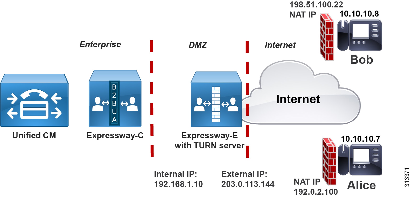
Figure 4 illustrates a basic call flow in this architecture between two endpoints enabled for mobile and remote access (MRA). The call consists of two independent media legs, each of which terminates on the Expressway-C B2BUA. The B2BUA then bridges the two media legs together (flow 1). In the case of a peer-to-peer connection achieved through ICE, the B2BUA must be able to remove itself from the media path. This will happen after the connectivity check between the endpoints has been successful. When Expressway-C and Expressway-E understand that the two endpoints are able to send media directly, Expressway removes itself from the media path but remains in the signaling path (flow 2 in Figure 4). Every ICE-enabled call first establishes a media flow through Expressway-C, and only after successful establishment of ICE, the media will start flowing peer-to-peer or through the TURN server.
Figure 4 Basic Call Flow for ICE Enabled Endpoints
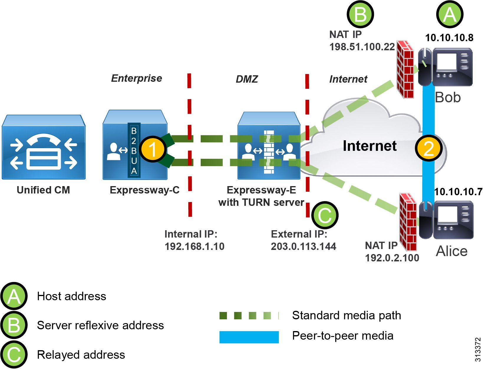
In the initial phase, a client communicates with the TURN server to obtain the other peer's transport addresses. A transport address is defined as the combination of an IP address and UDP port number. There are three different transport addresses that an endpoint might use. The native transport IP address of the client is called the host address (address A in Figure 4); the IP address and UDP port as seen by the TURN server after NAT has been applied is called the server reflexive address (address B in Figure 4); and the endpoint-mapped address on the TURN server is called the relayed address (address C in Figure 4). The TURN server sends the endpoint the server reflexive address and the relayed address during this initial phase.
Those addresses (A, B, and C) populate the SIP SDP offer and answer as ICE candidates, and after the signaling has gone through, both endpoints will have the remote party ICE candidate addresses. It is at that point that the endpoints do a connectivity check by sending STUN messages to one another in an attempt to punch transport holes in the firewalls in order to establish media connectivity between peers.
It is worth noting that for every m line in the SDP (such as audio, video, and so on) there will be two different transport addresses, one for the SRTP and the other for the RTCP. In Example 1, Bob, whose host IP address is 10.10.10.8, starts a call to Alice. After the initial TURN requests and responses, the call sends an SDP similar to the one in the Example 1 log file.
Example 1 shows the following information:
- Host address: 10.10.10.8
- Media type: audio
- Source UDP port: 19140
- Source RTCP port: 19141
- Server Reflexive address: 198.51.100.22
- Translated ports: unaffected
- Relayed address for audio: 203.0.113.144:24000
- Relayed address for RTCP: 203.0.113.144:24001
The relayed address serves an important role in that, if UDP packets are sent to 203.0.113.144 with port number 24000, the TURN server knows that this address corresponds to Bob's IPs (198.51.100.22 and 10.10.10.8) and port numbers (19140 and 19141), and it would thus "relay" the media sent to that public transport address (IP address and port).
An ICE-enabled call between two MRA endpoints involves the following actions:
- Before sending the INVITE, the calling endpoint starts a session with the TURN server to obtain its own server reflexive transport address (client NATed IP) and an associated relayed transport address (Expressway-E TURN server) that will be used in case the peer-to-peer communication is not possible.
- The host, the server reflexive (client NATed IP), and the relayed transport addresses (Expressway-E TURN server IP) are then sent as ICE candidates in the SDP INVITE.
- The INVITE is then forwarded by Expressway-E, Expressway-C, and Unified CM toward the called MRA device.
- When the called device receives the INVITE, it starts communicating with the Expressway-E TURN server in order to obtain its own host, server reflexive, and relayed transport addresses.
- The called endpoint then includes those addresses as ICE candidates in the SDP response.
- Once the signaling is completed, both endpoints have the respective host, server reflexive, and relayed addresses of the other device, and they can start the connectivity check phase.
- The connectivity check is performed by using the STUN protocol (see Figure 5). Each endpoint sends UDP traffic to the other endpoint's host, server reflexive, and relayed transport addresses. If host-to-host and server reflexive to server reflexive binding requests fail, the media will then be sent through the TURN server.
Figure 5 Example STUN Connectivity Check Flow Between Bob and Alice
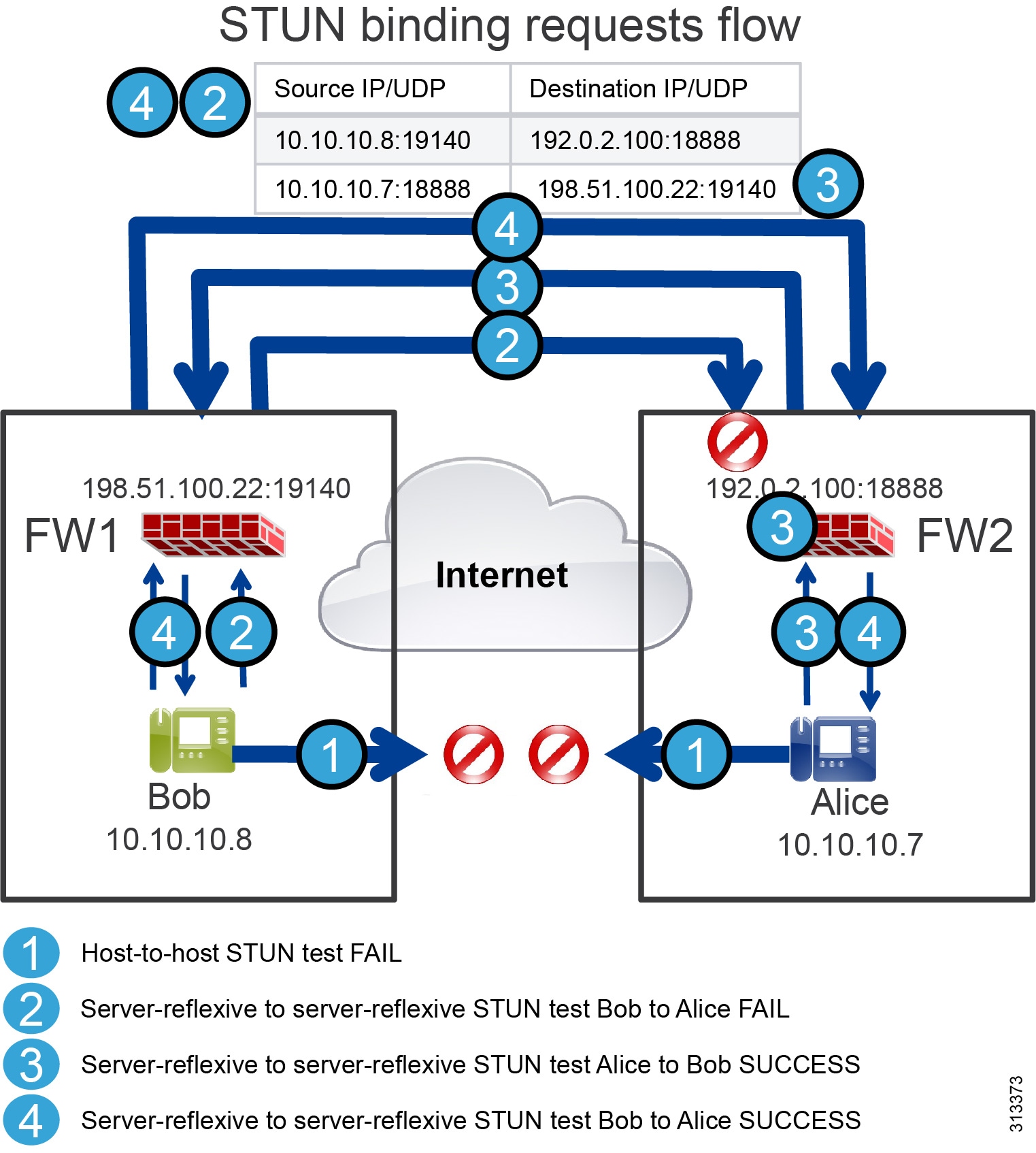
Figure 5 highlights the following steps of an example STUN connectivity check flow:
1.![]() Both Alice and Bob’s endpoints will try to determine if there is direct connectivity through the host transport address. Because they are on different networks behind different firewalls, those packets are not acknowledged.
Both Alice and Bob’s endpoints will try to determine if there is direct connectivity through the host transport address. Because they are on different networks behind different firewalls, those packets are not acknowledged.
2.![]() Their endpoints also test the connectivity using the server reflexive address. Bob’s endpoint sends a UDP packet simulating the audio media traffic (STUN packet) to Alice's server reflexive transport address, which is 192.0.2.100 with destination UDP port 18888. Bob's source transport address is 10.10.10.8 and UDP port 19140 (this address is translated by NAT before reaching Alice's firewall external interface). Once this packet reaches Alice's firewall, it is dropped by the firewall.
Their endpoints also test the connectivity using the server reflexive address. Bob’s endpoint sends a UDP packet simulating the audio media traffic (STUN packet) to Alice's server reflexive transport address, which is 192.0.2.100 with destination UDP port 18888. Bob's source transport address is 10.10.10.8 and UDP port 19140 (this address is translated by NAT before reaching Alice's firewall external interface). Once this packet reaches Alice's firewall, it is dropped by the firewall.
3.![]() Alice’s endpoint, however, also sends a STUN packet to Bob's server-reflexive transport address. The packet has 10.10.10.7:18888 as the source transport address and 198.51.100.22:19140 as the destination address. This packet is also translated by NAT by Alice's firewall, and it reaches Bob's firewall with the source address of 192.0.2.100:18888.
Alice’s endpoint, however, also sends a STUN packet to Bob's server-reflexive transport address. The packet has 10.10.10.7:18888 as the source transport address and 198.51.100.22:19140 as the destination address. This packet is also translated by NAT by Alice's firewall, and it reaches Bob's firewall with the source address of 192.0.2.100:18888.
4.![]() When this packet reaches Alice's firewall, if the firewall is configured for UDP stateful filtering inspection, it will understand that this UDP packet is part of the flow that Alice has initiated because it is using the same source and destination IP addresses and ports, and it will deliver the packet to Alice. On the other side, Alice’s endpoint keeps sending the same STUN packet to Bob's server reflexive transport address, and this time the packet will go through because Bob has also initiated a UDP connection to Alice using the same IP addresses and ports that Alice is using. If Bob's firewall is configured for UDP stateful filtering inspection, this time the packet will go through and the connectivity check will be successful.
When this packet reaches Alice's firewall, if the firewall is configured for UDP stateful filtering inspection, it will understand that this UDP packet is part of the flow that Alice has initiated because it is using the same source and destination IP addresses and ports, and it will deliver the packet to Alice. On the other side, Alice’s endpoint keeps sending the same STUN packet to Bob's server reflexive transport address, and this time the packet will go through because Bob has also initiated a UDP connection to Alice using the same IP addresses and ports that Alice is using. If Bob's firewall is configured for UDP stateful filtering inspection, this time the packet will go through and the connectivity check will be successful.
The scenario in Figure 5 can have any of the following possible outcomes:
- If the direct connection via the host address or server reflexive address cannot be achieved, then connectivity through the TURN server should be granted because the prerequisite for ICE to be set up successfully is for the TURN server to be reachable.
- If there is an ICE path (via the host, server reflexive, or relayed address) the ICE controlling agent will send a re-INVITE to the other endpoint, this time specifying only the chosen candidate. This re-INVITE will go through Expressway-E, Expressway-C, and Unified CM. But as long as Expressway-C and Expressway-E understand that the host-to-host connectivity check or the server reflexive to server reflexive connectivity check is successful, they will not put themselves into the media path, so the media will flow directly between the two endpoints.
- If the only successful checks are those against the TURN server, the media will flow through Expressway-E using the TURN server ports.
- If one of the two endpoints does not support ICE or does not satisfy the ICE prerequisites, the call will follow the legacy media path through Expressway-E and Expressway-C.
Expressway Deployment with NAT
NAT is an inherent part of the architecture, but there a few design considerations to be aware of in this preferred architecture (as described in the following sections):
Jabber and hardware phone addresses can be translated dynamically by NAT. However, if one of the two clients is behind a router or firewall performing symmetric NAT, direct media will always fail, and the media will flow through the TURN server.
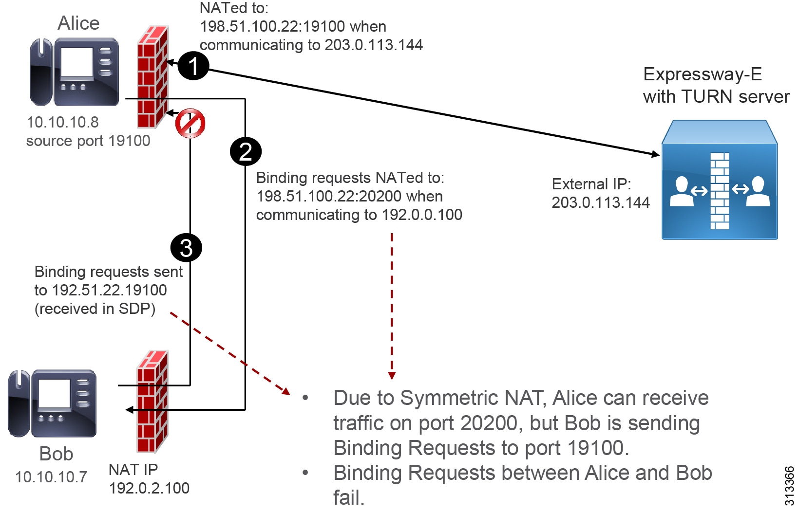
Symmetric NAT happens when the source transport address is translated in different ways based on the destination address. As an example, when an endpoint is talking to the TURN server, the endpoint address could be translated by NAT with a source port of 19100, as shown in step 1 of Figure 6. This port would be detected by the TURN server and sent back in the Allocate Response to the client, and the client would include it in the SDP as the server reflexive candidate. When the called endpoint receives the SDP, it will know that it must send traffic using port 19100 (step 2 in Figure 6).
However, when Alice's device starts the STUN connectivity check toward Bob, it will be NATed differently. The firewall will use a different port, such as 20200. The firewall will open a pinhole for that port toward Bob. When Bob’s endpoint starts the STUN connectivity check, it will send packets to 19100, and those packets will be discarded by the firewall (step 3 in Figure 6). As a consequence, the server-reflexive to server-reflexive connectivity check will fail. In this case the alternate media path will go through the TURN server.
Figure 6 Symmetric NAT Breaks STUN Connectivity Check
Static NAT on Expressway with Dual NIC Designs
The Expressway-E external interface address can be translated by static NAT. However, if you are using Expressway-E with a dual interface, Expressway-E will always use the external IP address for the TURN server. This means that NAT reflection should be configured in the external firewall. However, because NAT reflection might be considered to be a security threat, the administrator might prevent it. If NAT reflection is not configured, the media path through the TURN server will never be chosen (path 2 in Figure 1 and Figure 2). In this scenario either ICE will consider the peer-to-peer media path (path 3 in Figure 1 and Figure 2), or the standard media path (path 1 in Figure 1 and Figure 2) will be established.
ICE Provisioning
ICE is provisioned during configuration download. The administrator can configure ICE using the Common Phone Profile on Cisco Unified CM. Multiple Common Phone Profiles can be configured and assigned to a group of phones. The Common Phone Profile can be used to enable ICE, configure the TURN server and TURN server backup, and specify other ICE-related settings.
Currently, ICE endpoints do not support a secondary TURN server. If the primary TURN server is down, endpoints will still be able to communicate but ICE will not be triggered.
Security
Although ICE and encryption are two different, unrelated technologies, Cisco’s implementation of ICE requires end-to-end encryption. The reason is that SRTP encryption keys are negotiated end-to-end by the endpoints and sent in encrypted SDP. If the endpoints are able to communicate with together, the B2BUA on Expressway-C will not be engaged. This means that the SRTP keys will be sent unchanged in the SDP through the entire path involving the endpoints, Expressway-E, Expressway-C, and Unified CM. If the signaling connection between Expressway-C and Unified CM is clear, those keys would be exposed during the signaling phase. To mitigate this risk, signaling must be encrypted end-to-end.
There are three different authentication and encryption configurations for ICE support, based on endpoint type:
- Jabber clients only — Enable SIP Oauth and encrypted phone profiles for Jabber clients. The SIP OAuth feature is enabled on Unified CM, but it does not require Unified CM to be in mixed mode.
- Hardware devices — Set Unified CM to mixed mode and configure encrypted phone profiles. This does not require CAPF enrollment for devices that are connected over the Internet.
- Jabber clients and hardware devices — Set Unified CM to mixed mode, enable SIP OAuth, and configure encrypted phone profiles.
Media Port Planning
During the initial phase of ICE, before the connectivity check is done, the media starts flowing through the legacy media ports on Expressway-E. Those UDP ports are set by default on Expressway-E and are in the range of 36002 to 59999. The same range must be opened in the external firewall. However, the administrator might want to reduce the port range for security reasons. In that case the following information should be considered:
A video device with dual screens would be able to send and receive up to 6 different media types: audio, video, second video channel, BFCP, iX (multipoint control signaling), and FECC (Far End Camera Control). Each media type requires two UDP ports, one for RTP and another for RTCP, holding to 12 UDP ports per call. However, if the endpoint is capable of audio only (such as a Cisco IP Phone 7800 Series), it will use only 2 UDP ports per call. If the endpoint is able to send and receive audio and video but does not have any other capability (such as a Cisco IP Phone 8800 Series), it will use 4 UDP ports per call. If the administrator does not know the exact mix of endpoints that are deployed over Mobile and Remote Access (MRA), we recommend using the maximum value of 12 UDP ports per call.
As an example, if the number of concurrent calls does not exceed 50, then 600 UDP ports would be required to be opened on Expressway-E and in the external firewall. When a port range is configured on Expressway, Expressway splits the range into two blocks and assigns the first block to the Expressway proxy and the second block to the Expressway B2BUA. Those are two separate processes inside the same Expressway. Thus, if 600 UDP ports are needed, the range could be configured between 36002 to 37201. The first half (36002 to 36601) would be assigned to the proxy, and the second half (36602 to 37201) to the B2BUA. Consequently, because B2BUA is never engaged on MRA calls on Expressway-E, the range 36002 to 37201 must be opened in the external firewall.
TURN Media Relay Allocations
The TURN server allocates a relay address for each RTP and RTCP port advertised by the endpoint. If the device supports the 6 different media types described above, the TURN server will allocate 10 ports for each device in a call (considering that some of those media types do not require an RTCP port). For an ICE call including 2 endpoints, 20 TURN relay addresses will be used. For 60 concurrent calls, 1200 relay addresses on TURN will be used if the devices support all 6 media types.
The TURN media port range must be configured in the TURN server. By default, the UDP port range is 24000 to 29999. This number could be reduced based on the considerations described in the previous section on Media Port Planning.
ICE Calling Scenario Exceptions
ICE is engaged when both endpoints support ICE, have encrypted phone profiles, and are off-premises. As a consequence, in the following scenarios endpoints will not be able to negotiate ICE:
- If one endpoint is off-premises and another is on-premises, the standard media path though Expressway-C and Expressway-E is selected, regardless of whether the endpoints support ICE and encryption.
- If both endpoints are off-premises and both support ICE, but only one of them has an encryption phone profile, ICE is not used.
- If both endpoints are off-premises and both have encrypted phone profiles, but only one of them supports ICE, ICE is not used.
- During mid-call features and on PSTN, multi-point, or Cisco Unity Connection calls, ICE is not used.
As an example, assume two endpoints are on a call and ICE has negotiated a direct media path between them. If the call is put on hold, the media (MoH) starts flowing from Unified CM. When the call is resumed, ICE negotiation starts from the beginning and media will flow directly between the endpoints.
Multiple Expressway Pairs
ICE is supported across multiple Expressway clusters (see Figure 7). Multiple Expressway clusters can be deployed together with a single Cisco Unified CM cluster for two main reasons:
Figure 7 Media Flows in a Multi-Site Expressway Pair Deployment for MRA

When Alice and Bob are in different Expressway clusters, they communicate through different TURN servers. For example, if Alice is in Location 1 and Bob in Location 2, as shown in Figure 7, they communicate via multiple potential media paths 1 through 3.
Both devices receive the host candidate, server reflexive, and relay candidate of the remote device. Alice's relay candidate points to the TURN server in Location 1, while Bob's relay candidate indicates the TURN server in Location 2. During connectivity checks, all of those candidates are evaluated. This means that both Bob and Alice's devices also have the possibility of sending the media to the remote TURN server, allowing for more media path possibilities, as Figure 7 shows.
In this scenario, call admission control management differs from the implementation proposed in the Preferred Architecture for Cisco Collaboration 12.x Enterprise On-Premises Deployments, CVD. When media flows through the host, server reflexive, or relay candidates, bandwidth should not be deducted. Therefore, media flows 2 and 3 in Figure 7 should not deduct bandwidth from call admission control (CAC). For more information on this topic, see the section on Bandwidth Management.
Unified CM Multi-Cluster Deployments
Multiple Cisco Unified CM clusters are supported with ICE. In general, Unified CM does not participate in ICE because it is not in the media path. However, Unified CM does the following with regard to ICE:
- Provisions ICE and TURN for the endpoints and clients
- Allows SIP SDP with ICE candidates to flow transparently through line-side registration and trunks
Because ICE requires calls to be encrypted end-to-end, in a Unified CM multi-cluster deployment the trunks connecting the clusters must be configured with TLS and must allow for SRTP.
ICE does not require any other configuration for multiple Unified CM clusters. When endpoints are able to communicate using end-to-end encryption, ICE must be configured cluster-per-cluster.
Collaboration Edge Deployment Overview
Perform these steps to configure and enable ICE:
–![]() Select the default candidate type (host or server reflexive).
Select the default candidate type (host or server reflexive).
–![]() Enable the server reflexive candidate.
Enable the server reflexive candidate.
–![]() Specify the primary TURN server.
Specify the primary TURN server.
–![]() Specify the username and password used to communicate to the TURN server.
Specify the username and password used to communicate to the TURN server.
- Configure multiple Common Phone Profiles with different TURN servers so that the ICE load can be shared across the Expressways.
- For hardware devices, set Unified CM to mixed mode. Also configure an encrypted phone profile, and assign the encrypted phone profile and the Common Phone Profile to each endpoint. Note that the encrypted phone profile name must be listed as SAN in the Expressway-C certificate. For more detailed information, refer to the Mobile and Remote Access via Cisco Expressway Deployment Guide (X12.5).
- For Jabber, enable SIP OAuth with the CLI command utils sip-oauth enable. (For an explanation of SIP OAuth, see SIP OAuth with Jabber.) Configure an encrypted phone profile by checking the Enable OAuth Authentication check-box. Assign the encrypted phone profile and the Common Phone Profile to the endpoint. Note that SIP OAuth uses different ports for TLS. By default, Cisco Unified CM lists to TCP port 5090 for Jabber endpoints registered on-premises, and port 5091 for Expressway-C communicating with Unified CM. The administrator can change those TCP ports. This operation should be repeated for every server in the cluster.
1.![]() Go to Configuration > Zones > Zones.
Go to Configuration > Zones > Zones.
2.![]() Choose the Unified Communications traversal zone to Expressway-E.
Choose the Unified Communications traversal zone to Expressway-E.
3.![]() In the SIP pane, set ICE Passthrough support to On and ICE Support to Off.
In the SIP pane, set ICE Passthrough support to On and ICE Support to Off.

Note![]() ICE support is different than ICE Passthrough. With ICE Support, Expressway acts as an ICE client and performs connectivity checks on behalf of a client. ICE Support is a legacy feature that does not function with mobile and remote access (MRA). ICE Passthrough, on the other hand, enables Expressway to allow the two ICE endpoints to negotiate direct media by removing itself from the media path while remaining in the signaling path.
ICE support is different than ICE Passthrough. With ICE Support, Expressway acts as an ICE client and performs connectivity checks on behalf of a client. ICE Support is a legacy feature that does not function with mobile and remote access (MRA). ICE Passthrough, on the other hand, enables Expressway to allow the two ICE endpoints to negotiate direct media by removing itself from the media path while remaining in the signaling path.
- Enable TURN services.
- Specify an authentication realm to match the TURN Server Username configured in the Cisco Unified CM Common Phone Profile.
- Configure a username and password to match the username and password in the ICE section of the Common Phone Profile on Cisco Unified CM, and set the same password that has also been set in the Common Phone Profile.
Bandwidth Management
This section describes the architecture and design recommendations for Unified CM Enhanced Locations Call Admission Control (ELCAC) for MRA endpoints with ICE enablement for media optimization.
Bandwidth Management Architecture
Deploying MRA for Jabber and hardware endpoints in an enterprise environment where Enhanced Locations CAC is implemented requires the deployment to follow specific device mobility considerations. Those considerations are covered in detail in the Bandwidth Management chapter of the Preferred Architecture for Cisco Collaboration 12.x Enterprise On-Premises Deployments, CVD. If you plan to enable ICE for media optimization for MRA endpoints and you currently have Enhanced Locations CAC (ELCAC) deployed, then it is important to implement the following design recommendations to ensure the continued and proper functioning of ELCAC in this environment. If you have not implemented ELCAC, then these design recommendations do not apply.
When deploying ICE enablement for MRA endpoints in multi-cluster expressway environments, it is important to ensure that all ICE flows either follow media path 3 (Figure 7) or fail-over to path 2 (Figure 7) at a minimum. In multi-cluster expressway environments where media path 1 (Figure 7) can occur or is expected, media will flow from one Expressway-C to another Expressway-C in a different site and thus break the ELCAC design presented here. Therefore, before enabling ICE in environments with ELCAC and multiple Expressway clusters at separate locations, it is critical to know beforehand that ICE will be successful for media path 2 at a minimum, where the media path would be set up between Expressway-E servers as TURN servers.
The following section lists the recommendations and design considerations for enabling ICE on MRA endpoints with Enhanced Location Call Admission Control (ELCAC).
Recommendations and Design Considerations
With ICE enabled for MRA registered endpoints, the media no longer flows through the enterprise when those endpoints call other MRA registered endpoints also located on the Internet. Therefore, the locations CAC design has to be modified slightly.
Figure 8 illustrates an example configuration for locations and links in Unified CM that integrate bandwidth tracking for media flows that traverse the enterprise, while still allowing media flows over the Internet for MRA registered endpoints with ICE enabled without tracking their bandwidth over the Internet.
Figure 8 Unified CM Locations and Links for Remote and Mobile Access with ICE Enabled
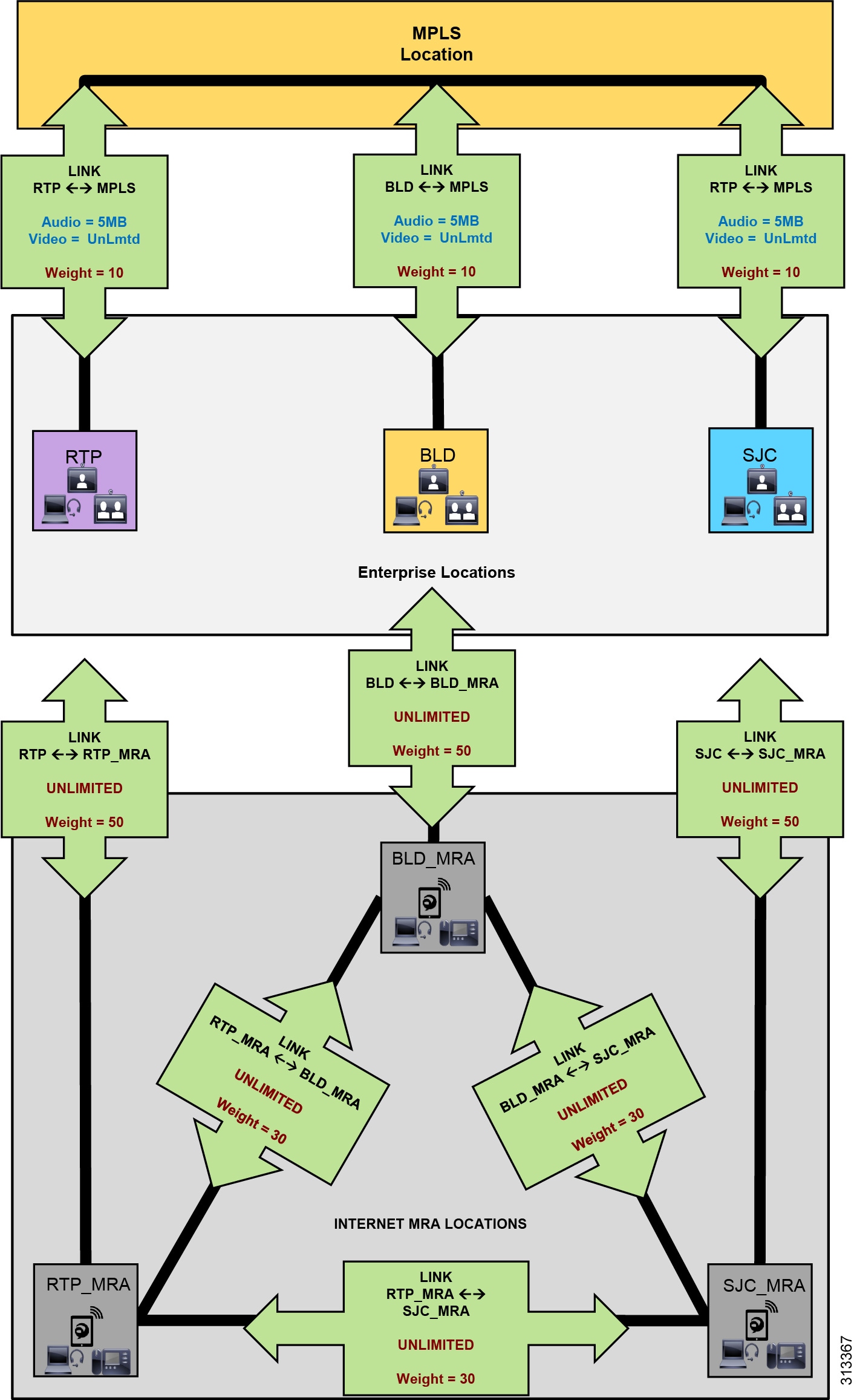
The example in Figure 8 shows a deployment of Unified CM ELCAC consisting of three main sites: RTP, BLD, and SJC. These sites are all connected to an MPLS provider and thus each has a separate WAN connection to the MPLS cloud location. Locations and links are created accordingly so that the enterprise locations are linked directly to a location called MPLS, with bandwidth links limited for audio and video calls mapping to the network topology. Devices are located in one of the three sites when in the enterprise and thus have a location associated to them (RTP, BLD, SJC). Each of these sites has a Cisco Expressway solution for VPN-less mobile and remote access (MRA) for Internet-based endpoints registered to Unified CM. Three new locations are configured for the Internet-based devices, one for each Expressway solution site, named RTP_MRA, BLD_MRA, and SJC_MRA. These three locations represent "Internet locations" because they are locations for devices registering from the Internet to Unified CM through an Expressway pair.
The three Internet locations in Figure 8 are further interconnected with direct links. This design for Locations CAC with ICE enabled differs from the design in the Preferred Architecture for Cisco Collaboration 12.x Enterprise On-Premises Deployments, CVD, where the Internet locations (RTP_MRA, BLD_MRA, and SJC_MRA) are not interconnected with links. However, when MRA endpoints are enabled with ICE, it is important to interconnect the Internet locations with links to ensure that bandwidth is not deducted for calls between MRA registered endpoints. With ICE enabled for MRA endpoints, calls between endpoints registered through the same Expressway or different Expressways are routed through the Internet and no longer flow through the enterprise MPLS cloud. These Internet locations will thus have a link to their associated enterprise location. For example, RTP_MRA has a link to RTP, BLD_MRA has a link to BLD, and so forth. These links between the Internet locations and the enterprise locations should be set to unlimited bandwidth. In addition, the Internet locations should be fully meshed with links between one another and set to unlimited bandwidth.
To ensure that ELCAC functions properly, link weights are used to determine path selection of location-to-location calls. In this environment, with MRA devices with ICE enabled and located on the Internet, we want to ensure the following:
- Calls between MRA Internet-located devices do not deduct bandwidth from the enterprise bandwidth.
- Calls between MRA Internet-located devices and enterprise-located devices do deduct bandwidth over the appropriate enterprise path.
To achieve these goals, use the following rules for adding weights to location links to ensure that the effective path for ELCAC is correct for MRA call flows:
1.![]() Accumulative Enterprise Locations paths weight (for example, RTP <-10-> MPLS <-10-> BLD = 20) must be less than Internet locations link weight (for example, RTP_MRA <-30-> SJC_MRA = 30):
Accumulative Enterprise Locations paths weight (for example, RTP <-10-> MPLS <-10-> BLD = 20) must be less than Internet locations link weight (for example, RTP_MRA <-30-> SJC_MRA = 30):
(RTP <-10-> MPLS <-10-> BLD) = 20 < 30 = (RTP_MRA <-30-> SJC_MRA)
2.![]() The link weight between the breakout location and the Internet location (for example, RTP <-50-> RTP_MRA = 50) must be greater than the Internet locations link weight (RTP_MRA <-30-> SJC_MRA = 30):
The link weight between the breakout location and the Internet location (for example, RTP <-50-> RTP_MRA = 50) must be greater than the Internet locations link weight (RTP_MRA <-30-> SJC_MRA = 30):
(RTP <-50-> RTP_MRA) = 50 > 30 = (RTP_MRA <-30-> SJC_MRA)
With rule 1 it is important to find the costliest route (the route with the highest accumulative weight) from any location to any other location. This will be the route with the most links. In simple MPLS hub-and-spoke environments, this route is easy enough to identify because a call from one location to another uses 2 links (beginning location to MPLS location, and then MPLS location to terminating location). By default, every link is set to a weight of 50 unless otherwise changed. Thus, a simple hub-and-spoke setup will have a maximum accumulative path weight of 100. In more complex multi-hop environments, it is more difficult to ascertain the path weight, but there are serviceability tools in the Unified CM administration pages to help determine the paths and weights.
As mentioned, Enhanced Locations CAC for Cisco Expressway deployments requires the use of a feature in Cisco Unified CM called Device Mobility. For details about this feature, see Deploy Device Mobility for Mobile and Remote Access (MRA) in the Preferred Architecture for Cisco Collaboration 12.x Enterprise On-Premises Deployments, CVD. The change from the deployment described in that document is that MRA endpoints will no longer be associated to the breakout locations (RTP, BLD, and SJC) but instead will be associated to the Internet locations (RTP_MRA, BLD_MRA, and SJC_MRA).
Enabling Device Mobility on the endpoints lets Unified CM know when the device is registered through Expressway or when it is registered from within the enterprise. Device Mobility also enables Unified CM to provide administrative control for the device as it roams between the enterprise and the Internet. Device Mobility is able to do this by knowing that, when the endpoints register to Unified CM with the IP address of Expressway-C, Unified CM will associate the applicable Internet location to the endpoint. However, when the endpoint is registered with any other IP address, Unified CM will use the enterprise location that is configured directly on the endpoint (or from the device pool directly configured on the endpoint). It is important to note that Device Mobility does not have to be deployed across the entire enterprise for this function to work. Configuration of Device Mobility in Unified CM is required only for the Expressway IP addresses, and the feature is enabled only on the devices that require the function (that is to say, those devices registering through the Internet). Figure 9 illustrates an overview of the Device Mobility configuration.
Figure 9 Device Mobility Configuration and Location Association
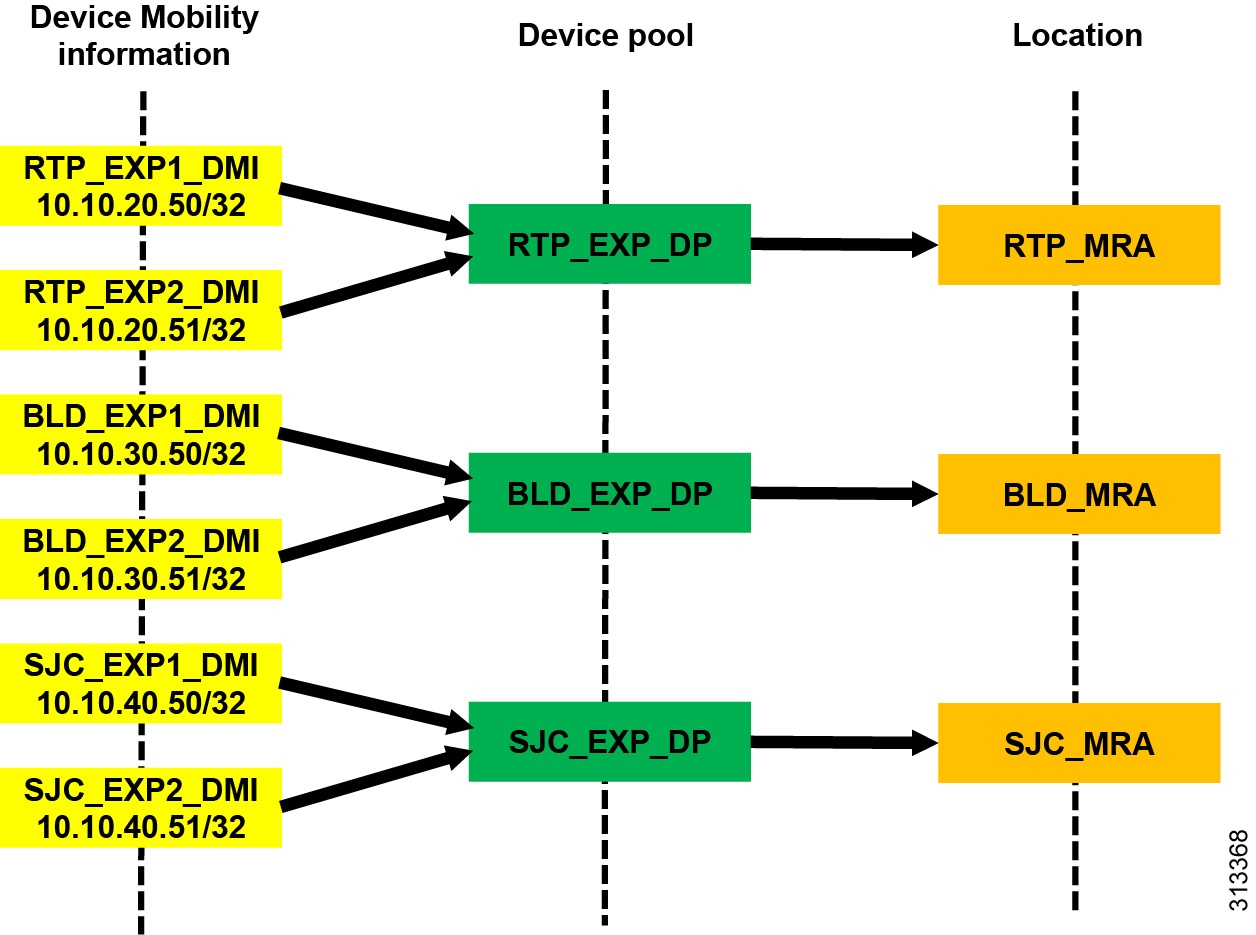
Figure 9 shows a simplified version of Device Mobility for the example deployment of ELCAC as described in Figure 8. The IP addresses of the Expressway-C servers are configured in the Device Mobility information. In this example there is a redundant pair of Expressway-C servers for each of the three sites, RTP, BLD, and SJC. RTP_EXP1_DMI and RTP_EXP2_DMI are configured respectively with the server IP addresses of the RTP Expressway-C servers. These two server IP addresses are associated to a new device pool called RTP_EXP_DP, which has the location RTP_MRA configured on it. Each site is configured similarly. With this configuration, when any device enabled for Device Mobility registers to Unified CM with the IP address that corresponds to the Device Mobility information in RTP_EXP1_DMI or RTP_EXP2_DMI, it will be associated with the RTP_EXP_DP device pool and thus with the RTP_MRA location.
With the above configuration, when an Internet-based MRA device registers through Expressway to Unified CM, it will register with the IP address of Expressway-C. Unified CM then uses the IP address configured in the Device Mobility information and associates the corresponding device pool and thus the Internet location associated to that device pool. Figure 10 illustrates this process.
Figure 10 Association of Device Pool and Location Based on Expressway IP Address
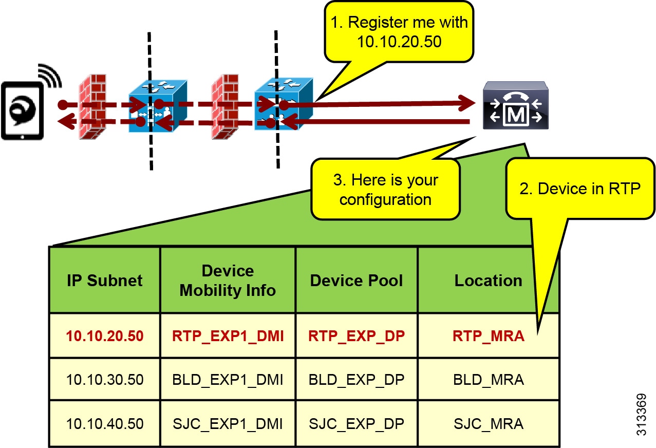
In Figure 10 the client registers with Unified CM through the Expressway in RTP. Because the signaling is translated at the Expressway-C in RTP, the device registers with the IP address of that Expressway-C. The device pool RTP_EXP_DP is associated to the device based on this IP address. The RTP_EXP_DP device pool is configured with the RTP_MRA location, and therefore that location is associated to the device. Thus, when devices register to the Expressway, they get the correct location association through Device Mobility. When the endpoint relocates to the enterprise, it will return to its static location configuration. Also, if the endpoint relocates to another Expressway in SJC, for example, it will get the correct location association through Device Mobility.
Bandwidth Management Deployment Overview
This section lists the steps to configure Unified CM Enhanced Locations CAC for ICE Enablement bandwidth management. The starting point for this configuration is after completion of the deployment of ELCAC recommendations covered in detail in the Bandwidth Management chapter of the Preferred Architecture for Cisco Collaboration 12.x Enterprise On-Premises Deployments, CVD.
Create Internet Locations for MRA Endpoints in Unified CM
- For each site with Internet access where an Expressway pair or pairs exist, create Internet locations for each site. Where a Cisco Expressway solution resides, requires an Internet location and an enterprise location. The enterprise location is associated to devices when they are in the enterprise (see locations RTP, BLD, and SJC in Figure 8). The Internet location is associated to the endpoints through the Device Mobility feature when the endpoints are registering from the Internet (see locations RTP_MRA, BLD_MRA, and SJC_MRA in Figure 8). For example, in Figure 8, RTP and RTP_MRA form a location pair for the physical site RTP.
- Configure enterprise locations according to applicable enterprise ELCAC design.
- Configure Internet locations with a single link to the enterprise location that they are paired with. For example, in Figure 8, RTP and RTP_MRA form an enterprise location and Internet location pair.
- Configure links from Internet locations to enterprise locations to have unlimited bandwidth. Unlimited bandwidth between these location pairs ensures that bandwidth is not counted for calls from the Internet location to the local enterprise location, and vice versa (for example, calls from RTP to RTP_MRA in Figure 8).
- In a Cisco Expressway solution where more than one Expressway site is deployed and requiring multiple Internet locations, it is important to ensure that Internet locations are fully meshed between one another and that the links are configured with unlimited bandwidth.
- Because links between Internet locations will create multiple paths in ELCAC, it is important to apply the following rules to correctly weight all of the location links in the enterprise and between the Internet locations.
Rules for location link weights:
1.![]() Accumulative Enterprise Locations paths weight must be less than Internet locations link weight:
Accumulative Enterprise Locations paths weight must be less than Internet locations link weight:
(RTP <-10-> MPLS <-10-> BLD) = 20 < 30 = (RTP_MRA <-30-> SJC_MRA)
2.![]() The link weight between the breakout location and the Internet location must be greater than the Internet locations link weight:
The link weight between the breakout location and the Internet location must be greater than the Internet locations link weight:
Contact Cisco
- Open a Support Case

- (Requires a Cisco Service Contract)
 Feedback