Preferred Architecture for Cisco Collaboration 14 On-Premises Deployments, Design Overview
Available Languages
Table of Contents
Preferred Architecture for Cisco Collaboration System Release 14 On-Premises Deployments
Documentation for Cisco Collaboration On-Premises Preferred Architecture
Cisco Integrated Services Routers and Aggregation Services Routers
Cisco Unified Survivable Remote Site Telephony
Multi-Cluster Deployment Considerations
Audio and Video Instant Conferences
Permanent Conferences with Cisco Meeting Server (CMS) Spaces
Support for Multiple Call Processing Sites
Managing Conferencing Resources
Collaboration Management Services
Cisco Prime Collaboration Deployment
Secure Infrastructure Recommendations
Device Hardening Recommendations
Bandwidth Management Architecture for Collaboration
Preferred Architecture for Cisco Collaboration System Release 14 On-Premises Deployments
Preface
Cisco Preferred Architectures provide tested and recommended deployment models for specific market segments based on common use cases. They incorporate a subset of products from the Cisco Collaboration portfolio that is best suited for the targeted market segment and defined use cases. These deployment models are prescriptive, out-of-the-box, and built to scale with an organization as its business needs change. This prescriptive approach simplifies the integration of multiple system-level components and enables an organization to select the deployment model that best addresses its business needs.
About This Guide
This document provides a high-level overview of the Preferred Architecture (PA) for on-premises deployments of Cisco Collaboration System Release (CSR) 14. It is intended for use in pre-sales discussions and decision making by:
- Sales teams that design and sell collaboration solutions
- Customers and sales teams who want to understand the overall collaboration architecture, its components, and general design best practices
This guide simplifies the design and sales process by:
- Recommending products in the Cisco Collaboration portfolio that are best suited for on-premises deployments and that provide appropriate feature sets for those deployments
- Describing the key components of the Preferred Architecture, their roles in that architecture, and the features and benefits they provide
This guide describes the Cisco Collaboration on-premises Preferred Architecture for Enterprise collaboration — Deployments of more than 1,000 users on a variety of platforms.
Readers of this guide should have a general knowledge of Cisco Voice, Video, and Collaboration products and a basic understanding of how to deploy these products. For detailed information about configuring, deploying, and implementing this architecture, consult the Cisco Validated Design (CVD) guides listed in the next section on Documentation for Cisco Collaboration On-Premises Preferred Architecture.
Documentation for Cisco Collaboration On-Premises Preferred Architecture
Figure 1 illustrates the various documents available for this Preferred Architecture (PA):
Preferred Architecture for Cisco Collaboration 14 On-Premises Deployments (this document)
–![]() Enterprise deployments (more than 1,000 users)
Enterprise deployments (more than 1,000 users)
Preferred Architecture for Cisco Collaboration 14 Enterprise On-Premises Deployments
The latest versions of these documents are available at: https://www.cisco.com/go/pa.
Figure 1 Preferred Architecture Documentation

In addition to the above documents for this Preferred Architecture, Cisco Solution Reference Network Design (SRND) guides provide detailed guidelines and recommendations to help customers and sales teams design collaboration solutions for deployments that have requirements outside the scope of the Preferred Architecture. The SRND guides are available at: https://www.cisco.com/go/srnd.
Introduction
In recent years, many new collaborative tools have been introduced to the market, enabling organizations to extend collaboration outside the walls of their businesses. Providing access to collaborative tools for employees outside the office is no longer a luxury; it is mandatory for businesses to stay relevant in today's market. Today's users expect immediate access to these tools from a wide variety of portable and mobile devices. Many of these same tools can be extended to customers and partners, helping strengthen these relationships.
Organizations realize the added value that collaboration applications bring to their businesses through increased employee productivity and enhanced customer relationships. Not long ago, interoperability among collaboration applications was sparse, and applications were difficult to deploy and use. Since then, significant advances have been made in the collaboration space, simplifying deployment, improving interoperability, and enhancing the overall user experience. Additionally, individuals have adopted a wide variety of smart phones, social media, and collaboration applications in their personal lives.
Organizations can now feel comfortable providing collaboration applications that employees will quickly adopt and that provide maximum value. These new collaboration tools enhance an organization's overall business processes, make its employees more productive, and open the door to new and innovative ways for communicating with business partners and customers. Today's collaboration solutions offer organizations the ability to integrate video, audio, and web participants into a single, unified meeting experience.
Technology Use Cases
Organizations want to streamline their business processes, optimize employee productivity, and enhance relationships with partners and customers. The Cisco Collaboration on-premises Preferred Architecture (PA) delivers capabilities that enable organizations to realize immediate gains in productivity and enhanced relationships. Additionally, the following technology use cases offer organizations opportunities to develop new, advanced business processes that deliver even more value in these areas:
- Consolidate communications infrastructure — Bring together voice, video, and data into a single IP network to simplify management and support effective communications.
- Incorporate video into meetings — Improve communications, relationships, and productivity by making it easier to meet face-to-face over distance.
- Extend telephony with video — Facilitate face-to-face video communications directly from end-user phones and softphone applications.
- Support teleworkers and branch offices — Let employees work from multiple locations, whether satellite offices, home offices, or when traveling.
- Collaborate with external organizations — Easily share information, interact in real time, and communicate using technologies beyond email and telephone.
- Create flexible work areas and office spaces — Scale office space and create work areas that foster employee inclusiveness, collaboration, innovation, and teamwork.
- Deploy a unified communications architecture — Provide the entire global organization with a unified network architecture built from components designed to work together for optimum performance.
Information about Cisco Collaboration Technologies and use cases is available on Cisco.com.
Architectural Overview
The Cisco Collaboration on-premises Preferred Architecture provides end-to-end collaboration targeted for a wide range of customers. This architecture incorporates high availability for critical applications. The consistent user experience provided by the overall architecture facilitates quick user adoption. Additionally, this architecture supports an advanced set of collaboration services that extend to mobile workers, partners, and customers through the following key services:
- Voice communications
- Instant messaging and presence
- High-definition video and content sharing
- Rich media conferencing
- Collaboration services for mobile and remote workers
- Business-to-business voice and video communications
- Unified voice messaging
- Customer care for midmarket deployments
Because of the adaptable nature of Cisco endpoints and their support for IP networks, this architecture enables an organization to use its current data network to support both voice and video calls. The Preferred Architecture provides a holistic approach to bandwidth management, incorporating an end-to-end Quality of Service (QoS) architecture, call admission control, and video rate adaptation and resiliency mechanisms to ensure the best possible user experience for deploying pervasive video over managed and unmanaged networks.
The Cisco Collaboration on-premises PA, shown in Figure 2, provides highly available and secure centralized services for enterprise and midmarket deployments. These services extend easily to remote offices and mobile workers, providing availability of critical services even if communication to headquarters is lost. Centralized services also simplify management and administration of an organization's collaboration deployment.
Figure 2 Cisco Collaboration On-Premises Preferred Architecture for Enterprise

Table 1 lists the products in this architecture. For simplicity, products are grouped into modules to help categorize and define their roles. The content in this guide is organized in the same modules.
Cisco Business Edition 7000
Cisco Business Edition 7000 (BE7000) serves organizations with 1,000 or more users, and it is the foundation of the Cisco Collaboration on-premises PA for enterprise deployments. The Cisco BE7000 is built on a Cisco Unified Computing System (UCS) that ships ready-for-use with a pre-installed virtualization hypervisor and application installation files. The Cisco BE7000 solution offers premium voice, video, messaging, instant messaging and presence, and contact center features on a single, integrated platform. For more information about the Cisco BE7000, see the data sheet.
Core Applications
In this Cisco Collaboration on-premises PA, the following applications are deployed on multiple Cisco Unified Computing System (UCS) servers to provide hardware and software redundancy:
- Cisco Unified Communications Manager
- Cisco Unified Communications Manager IM and Presence Service
- Cisco Unity Connection
- Cisco Expressway, consisting of Expressway-C and Expressway-E
- Cisco Meeting Server and Cisco Meeting Management
- Cisco TelePresence Management Suite and Extensions
- Cisco Prime Collaboration Deployment
We recommend always deploying redundant components and configurations to provide the highest availability for critical business applications. We also recommend deploying Cisco Meeting Server on a dedicated server.
High Availability
The Cisco Collaboration on-premises PA provides high availability for all deployed applications by means of the underlying clustering mechanism present in all Cisco Unified Communications applications.
Clustering replicates the administration and configuration of deployed applications to backup instances of those applications. If an instance of an application fails, Cisco Unified Communications services – such as endpoint registration, call processing, messaging, business-to-business communication, and many others – continue to operate on the remaining instance(s) of the application. This failover process is transparent to the users. In addition to clustering, the Cisco Collaboration on-premises PA provides high availability through the use of redundant power supplies, network connectivity, and disk arrays.
Licensing
Details about the individual licenses for the endpoints and infrastructure components in the Cisco Collaboration on-premises PA are beyond the scope of this document. Information about Cisco Collaboration licensing is available at
https://www.cisco.com/c/en/us/products/unified-communications/collaboration-flex-plan/index.html
Cisco Integrated Services Routers and Aggregation Services Routers
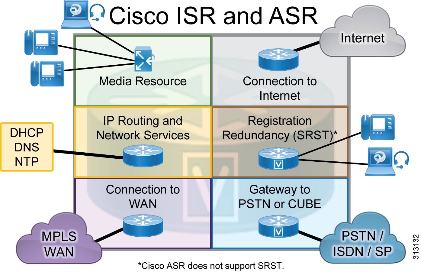
The Cisco Integrated Services Router (ISR) and Aggregation Services Router (ASR) provide Wide Area Network (WAN) and Cisco Unified Communications services in a single platform. In the Cisco Collaboration on-premises Preferred Architecture, the Cisco ISR and ASR can provide the following functions (Figure 3):
- External connectivity to the Internet
- IP routing and remote-site network services such as DHCP, DNS, NTP, and others
- Cisco Unified Survivable Remote Site Telephony (SRST) to service calls during WAN failures
- Voice gateway to the Public Switched Telephone Network (PSTN), or Cisco Unified Border Element (CUBE) for Session Initiation Protocol (SIP) trunks
- Integrated data and voice connectivity to service providers
- Multiprotocol Label Switching (MPLS) WAN connectivity for the organization's network
- Media resources for Cisco Unified Communications Manager (Unified CM)
Figure 3 Cisco ISR and ASR Functions
The Cisco ISR and ASR have additional slots that support add-on modules such as wireless controllers. Deployments can use various Cisco ISR and ASR models to support different features, to scale, and to accommodate additional services. Their modular design enables the Cisco ISR and ASR to be deployed at headquarters, remote locations, or branch locations. For more information about these routers, see the Cisco ISR and Cisco ASR data sheets.
Endpoints
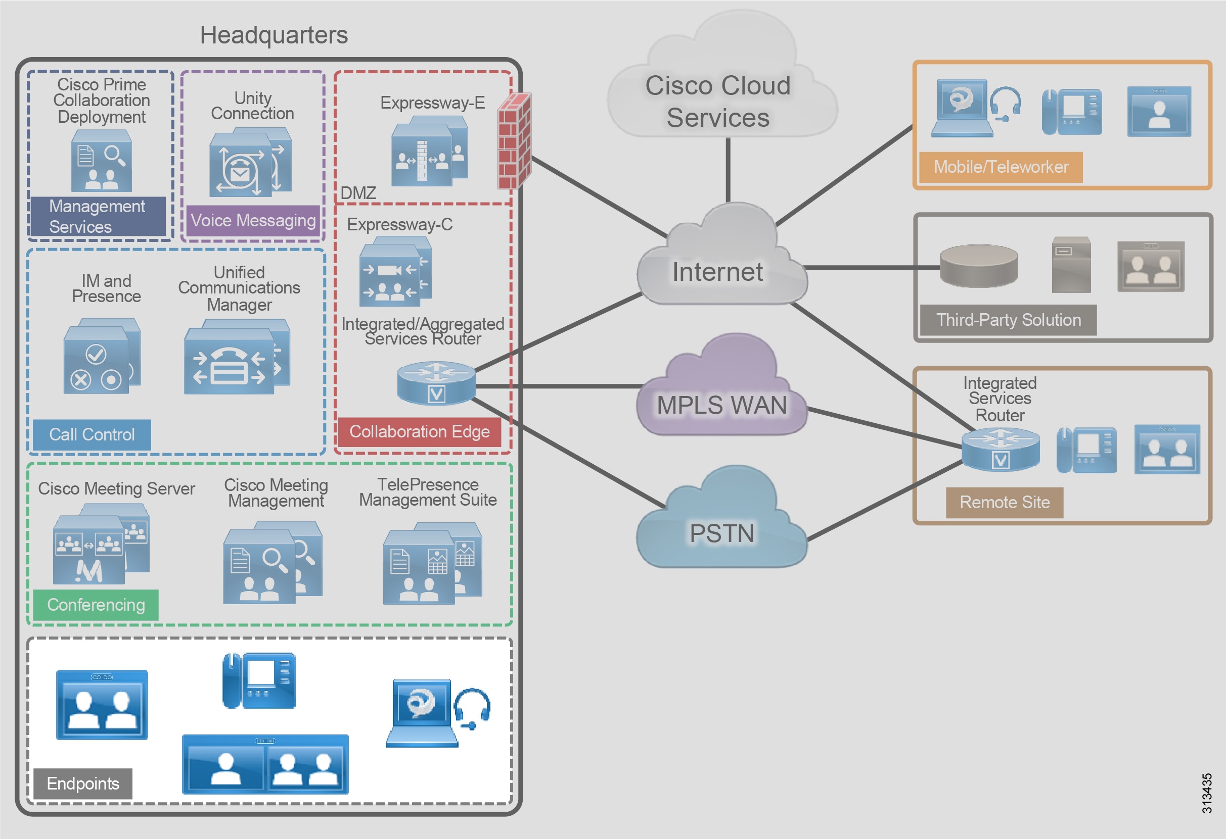
Cisco Collaboration endpoints provide a wide range of features, functionality, and user experiences. Because Cisco endpoints range from low-cost, single-line phones and soft clients to three-screen Cisco TelePresence endpoints, an organization can deploy the right variety of endpoints to meet users' needs (Figure 4). Additionally, these devices enable users to access multiple communication services such as:
Figure 4 Architecture for Endpoints
Recommended Deployment
Cisco Unified Communications Manager (Unified CM) is the call control server for the Cisco Collaboration on-premises Preferred Architecture. Cisco IP Phones, Jabber clients, and TelePresence video endpoints use SIP to register directly to Cisco Unified CM. The Unified CM cluster's failover mechanism provides endpoint registration redundancy. If a WAN failure occurs and endpoints at remote locations cannot register to Unified CM, they use SRST functionality for local and PSTN calls, but some services such as voicemail and presence might not be available.
We recommend the endpoints listed in the following tables because they provide optimal features for this design. Cisco has a range of endpoints with various features and functionality that an organization can also use to address its business needs.
| Soft client with integrated voice, video, voicemail, instant messaging, and presence functionality for mobile devices and personal computers |
|
Call Control
Call control is the core element for any communications deployment. It provides endpoint registration, call processing, and call admission control. Call control design considerations include the dial plan, endpoint addressing scheme, calling party presentation, call admission control, codec selection, PSTN connectivity, and general trunking requirements, as well as other factors.
Cisco Unified Communications Manager (Unified CM) provides a common call control platform for all Cisco Collaboration deployments (Figure 5). Having a highly available and common call control component for a communications infrastructure is crucial to provide consistent services for all devices and communication types and to preserve a uniform dial plan and a consistent feature set across the deployment.
Adding the IM and Presence Service to a Cisco Unified CM deployment provides instant messaging, network-based presence, and federation for third-party chat servers, and it enables the use of Cisco Jabber for instant messaging, presence, and audio and video communications.
Figure 5 Architecture for Call Control

Table 6 lists the roles of the call control components in this architecture and the services they provide.
Recommended Deployment
For call control in the Cisco Collaboration on-premises Preferred Architecture, we recommend the following:
- Deploy a single Cisco Unified CM cluster for an enterprise with a central site and remote offices. Deploy call processing subscribers in pairs for scalability and redundancy.
- Add additional Cisco Unified CM clusters for very large sites or for geographic and/or organizational separation. Configure SIP trunks to interconnect individual Cisco Unified CM clusters.
- Deploy a pair of IM and Presence Service servers in a cluster configuration. For enterprise deployments, you can add more pairs for scalability. (Increased scalability does not apply to midmarket deployments.)
- Enable SRST on the Cisco ISR as a backup service at remote sites to provide high availability.
- Enable Apple Push Notification service (APNs) for Apple iOS devices running Jabber for iPhone and iPad, so that these clients continue to receive incoming call and messaging notification even when running in the background.
Cluster Recommendations
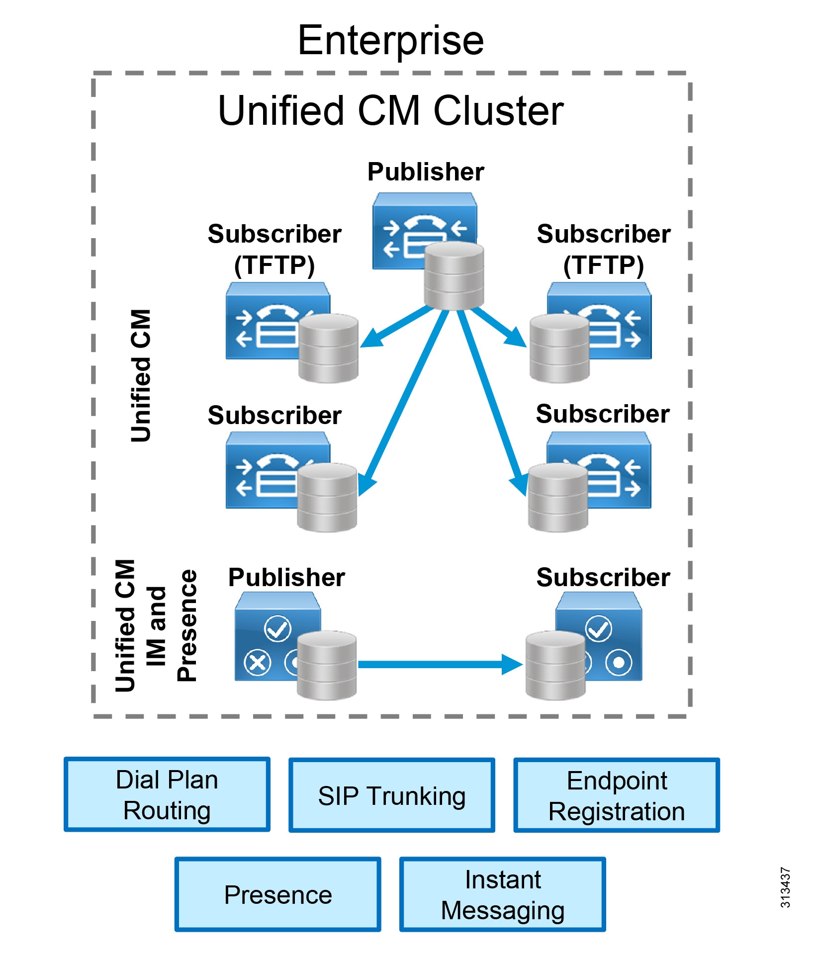
Cisco Unified CM and IM and Presence support clustering, which is the grouping of nodes that work together as a single logical entity. The publisher node contains the cluster's configuration database, which is replicated to the call processing subscriber nodes and TFTP nodes in the cluster.
Clustering provides an automatic redundancy mechanism for endpoints and for Cisco Unified CM services, such as the ability to receive and process incoming calls. To provide 1:1 redundancy, deploy call processing subscribers and TFTP nodes in pairs. (Figure 6) While the call processing subscribers provide endpoint registration and call processing capabilities, the TFTP nodes provide configuration and firmware updates to endpoints.
All the TFTP nodes and subscriber nodes periodically receive updates of the configuration database from the publisher node. These database updates enable all the subscriber nodes to operate in a consistent configuration state.
To provide load balancing of call processing services across the subscribers and to reduce failover response times, deploy each call processing subscriber pair in an active/active redundancy scheme.
For IM and Presence, we recommend deploying a minimum of one IM and Presence publisher and one subscriber. The IM and Presence publisher is not a dedicated node, and the publisher and subscriber provide redundancy for each other. (Figure 6)
For enterprise deployments, add more pairs of IM and Presence subscribers or Unified CM call processing nodes as needed to accommodate more users.
Figure 6 Cisco Unified CM Cluster
SIP Trunk Recommendations
Use SIP trunks from Cisco Unified CM to communicate with all the components in the Cisco Collaboration on-premises Preferred Architecture, including external entities such as third-party systems. SIP trunks offer the following benefits:
Cisco Unified Survivable Remote Site Telephony
The Cisco Survivable Remote Site Telephony (SRST) feature is critical for remote sites that require continuation of voice services during WAN outages. SRST runs on the same Cisco ISR that provides WAN and PSTN connectivity for the remote site. Deploy SRST on the Cisco ISR in the following cases:
- The remote site has local PSTN connectivity.
- The remote site does not have local PSTN connectivity but has more than 25 users.
To avoid interruption of external voice services if a WAN outage occurs, provide local PSTN connectivity at the remote site. SRST is required only if the remote site's WAN reliability does not match that site's required service level for voice service availability.
If a WAN failure occurs at a site with SRST and local PSTN access, the following services will still be available:
- Internal point-to-point voice calls
- External voice calls through the PSTN
- Call hold, transfer, and conference
- Music on hold

Note![]() SRST is not available for Webex Desk Pro or Webex Room Series endpoints. See Table 5 for information about endpoints that support SRST.
SRST is not available for Webex Desk Pro or Webex Room Series endpoints. See Table 5 for information about endpoints that support SRST.
Dial Plan
A structured, well-designed dial plan is essential to successful deployment of any call control system. When designing a dial plan, consider the following main factors:
Dialing habits describe what end users can dial to reach various types of destinations. Dialing habits can first be classified as numeric dialing (for example, 914085550123) or alphanumeric dialing (for example, bob@ent-pa.com). Typically, different types of destinations require support for different dialing habits. Further dialing habits might have to be defined for services such as call pick-up, voicemail, and others. Also, future growth should be considered so that more users and more sites can be added as needed without redesigning the dial plan. Some dialing habits, typically PSTN dialing habits in particular, need to follow country-specific requirements or established dialing procedures. Identifying dialing habits is most important when defining an enterprise dial plan in order to avoid overlaps between any two dialing habits.
Each endpoint registered with the enterprise call control must have a unique numeric address. Endpoint addresses in Cisco Unified CM are equivalent to the directory numbers provisioned on the lines of the endpoints. Use fully qualified PSTN numbers (E.164 numbers) with a leading "+" as endpoint addresses. This format is typically referred to as +E.164 format. The benefits of using +E.164 endpoint addresses include:
- Wide use in voice networks
- No need to develop and maintain an enterprise numbering scheme
- Easy creation of correct caller ID presentation for all on-cluster and off-cluster call flows
- Easy implementation of directory lookups
- Simplified alternate routing to the PSTN in cases of WAN failure or bandwidth constraints
- In addition to the primary numeric endpoint addresses, administrators can provision alphanumeric URIs (for example, bob@ent-pa.com) in Cisco Unified CM to serve as aliases for the primary addresses, and users can enter the URI as an alternate way to dial the destination endpoint.
The routing portion of the dial plan enables users to reach the correct destinations when they use the defined dialing habits.
The primary numeric routing is based on +E.164 numbers. External routes to other transport networks such as the PSTN also use the +E.164 scheme. Endpoint addresses in +E.164 provide +E.164 on-net dialing without any further configuration. All other numeric dialing habits, such as abbreviated inter-site and intra-site dialing, are implemented as overlays by adding the appropriate translation patterns to the dial plan to map from the implemented dialing habit to the +E.164 global routing address format. This allows users to reach the same endpoint by means of different dialing habits, depending on user preference.
Alpha-numeric URIs, as aliases for numeric addresses, provide an alternative means of reaching endpoints. The benefits of URI dialing and routing include:
- Conformity with the native dialing habit on most video systems
- Easier business-to-business connectivity
- Direct mapping from instant messaging identifiers to addresses (easier escalation of business-to-business IM sessions to voice and/or video), although technically IM identifiers and SIP URIs are not necessarily identical
To enable users to search contacts and dial from the directory, integrate Cisco Unified CM with the organization's LDAP directory. Although Unified CM allows the creation of local user contacts, LDAP directory integration is required when using Cisco Jabber because it provides a single location for directory management and enables users to authenticate to Cisco Unified CM and Cisco Jabber by using their LDAP directory credentials.
Cisco Unified CM pulls user and contact information from LDAP directories and synchronizes user parameters – name, surname, username, telephone number, and SIP URI – when changes occur. The IM and Presence Service pulls user and contact information from Cisco Unified CM.
Classes of service define which users can access which services, such as allowing only emergency and local calls from lobby phones while allowing unrestricted calls from executive phones. The complexity of the dial plan is directly related to the number of differentiated classes of service it supports.
To define classes of service, configure partitions and calling search spaces in Cisco Unified CM. The number of classes of services supported by a dial plan depends on the granularity and complexity of the classes. For more information about classes of service and details on enterprise dial plan design, see the Cisco Collaboration SRND.
Multi-Cluster Deployment Considerations
Consider deploying more than one Cisco Unified CM cluster if you have any of the following requirements:
- Administrative separation — This includes the need to keep users from different parts of the organization on separate infrastructures, or the requirement to have different departments operate different parts of the communications infrastructure.
- Geographic footprint — Technical limitations such as excessive propagation delay might prohibit endpoint registrations (for example, endpoints in Asia registering to an enterprise call control hosted in the US).
In a multi-cluster deployment, interconnect all the individual Unified CM clusters through SIP trunks. To avoid session traversal through individual clusters, deploy a full mesh of SIP trunks. With four or more clusters, deploy Cisco Unified CM Session Management Edition to centralize the dial plan and trunking and to avoid the complexity of a full-mesh SIP trunk topology.
In multi-cluster deployments, use Global Dial Plan Replication (GDPR) to replicate dial plan information between clusters. GDPR can advertise a +E.164 number, one enterprise significant number (ESN), and up to five alpha-numeric URIs per directory number. An ESN is the abbreviated inter-site dialing equivalent of a directory number. The information advertised and learned through GDPR enables deterministic intercluster routing for these dialing habits:
Benefits
This deployment provides the following benefits:
- Call control is centralized at a single location that serves multiple remote sites.
- Common telephony features are available across voice and video endpoints.
- Single call control and a unified dial plan are provided for voice and video endpoints.
- Critical business applications are highly available and redundant.
Conferencing
The ability for three or more people to communicate in real time by using voice and video technologies is a core component of collaboration. Cisco rich media conferencing builds upon existing infrastructure in place for point-to-point calls, offering users a consistent voice and video experience (Figure 7).
Figure 7 Architecture for Conferencing
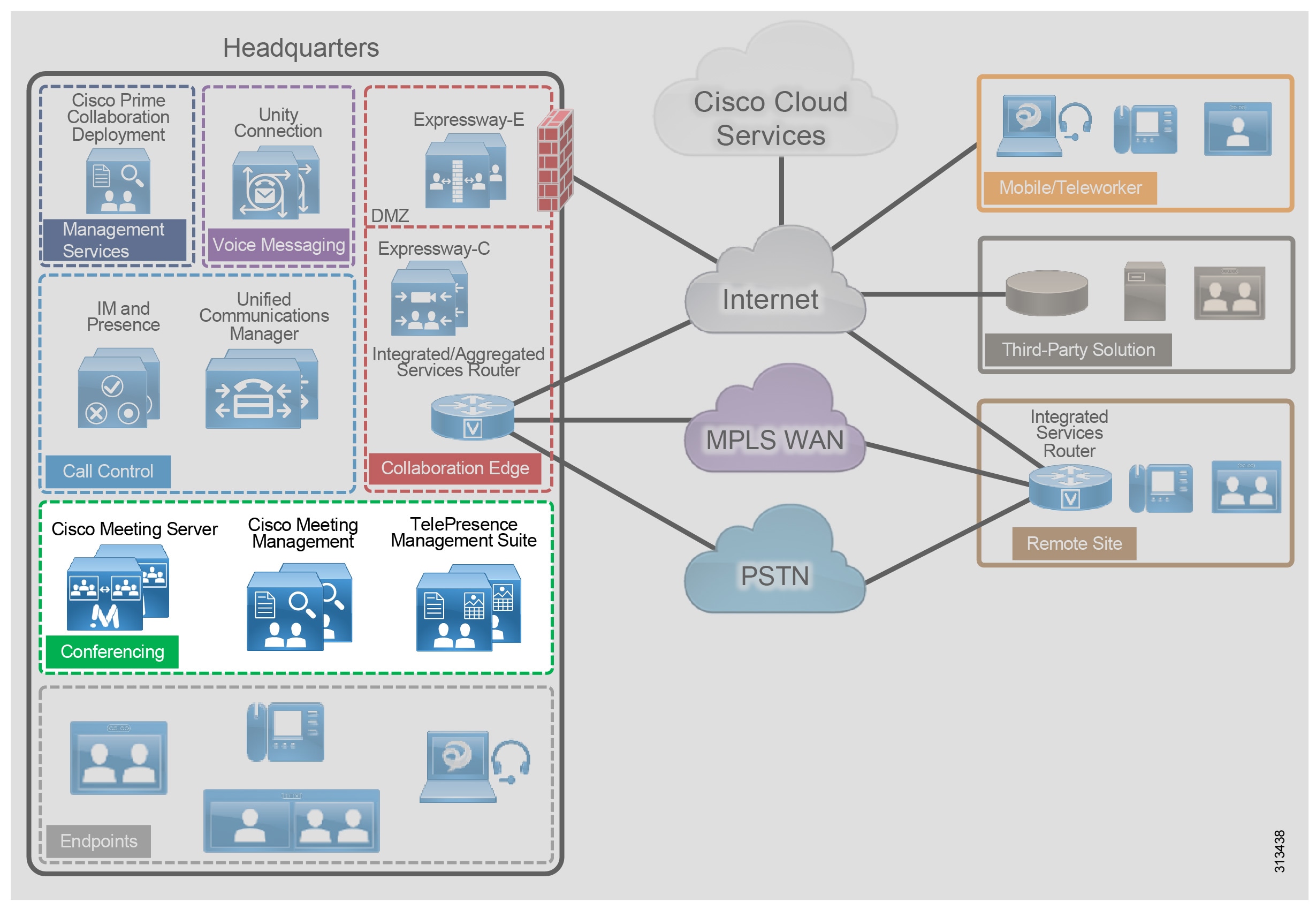
Table 7 lists the roles of the conferencing components in this architecture and the services they provide.
Provides Cisco Meeting Server meeting management as well as Cisco Meeting Server web app user provisioning. |
||
Provides conference scheduling and device management capabilities |
There are three types of conferences:
- Instant or ad hoc — A conference that is not scheduled or organized in advance; for example, a call between two parties who add other parties to the call.
- Permanent or rendezvous — A conference that requires callers to dial a predetermined number or URI to reach a shared conferencing resource. Meet-me, static, and rendezvous are other names for this type of conference.
- Scheduled — A conference planned in advance with a predetermined start time.
Recommended Deployment
For audio and video conferencing in the Cisco Collaboration on-premises Preferred Architecture, we recommend the following:
- Deploy Cisco Meeting Server for all conference types.
- Deploy Cisco Meeting Management for meeting management, license management and Cisco Meeting Server web app provisioning.
- Deploy Cisco Meeting Server in a cluster for high availability and increased scale.
- Integrate the Cisco Meeting Server cluster with Cisco Unified CM through SIP trunks and registered media resource conference bridges for instant conferences.
- Integrate the Cisco Meeting Server cluster with Unified CM through SIP trunks and route patterns for permanent and scheduled conferences.
- Integrate the Cisco Meeting Server with Cisco Meeting Management for meetings management.
- Integrate the Cisco Meeting Management with LDAP for CMS space creation and web app user provisioning.
- Deploy Cisco TelePresence Management Suite (TMS) to schedule conferences with Cisco Meeting Server. Deploy Cisco TelePresence Management Suite Extension for Microsoft Exchange (TMSXE) to allow end users to schedule meetings using Microsoft Outlook clients.
Audio and Video Instant Conferences
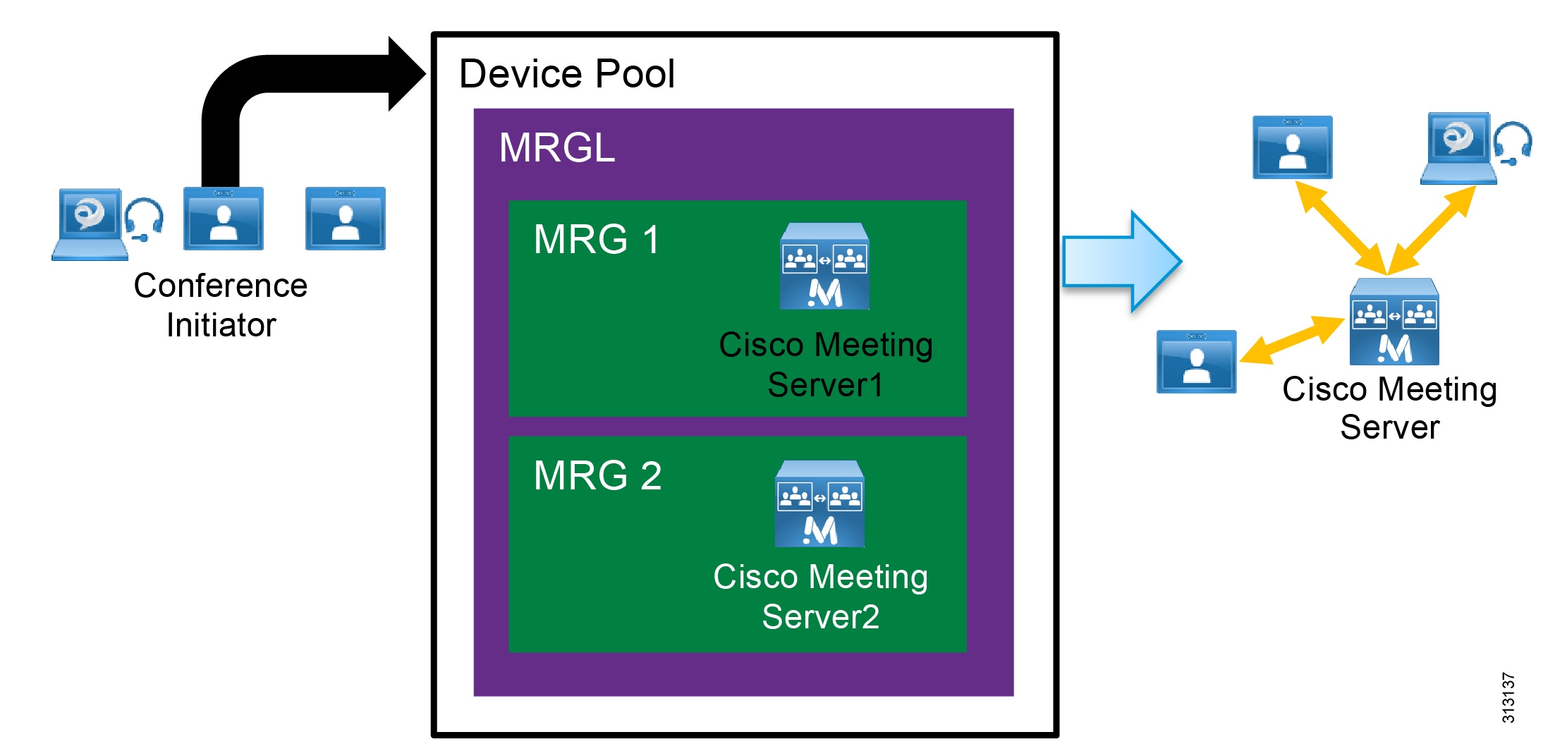
For instant audio and video conferences, use Cisco Meeting Server on-premises as the media resource. Cisco Unified CM has the HTTPS and SIP trunk interfaces to Cisco Meeting Server inside the instant conference bridges. HTTPS is used for conference control, while a SIP trunk is used for call signaling. These conference bridges are assigned to media resource group lists (MRGLs) and media resource groups (MRGs) in Unified CM. Unified CM uses MRGLs and MRGs to prioritize and allocate media resources such as conference bridges, music on hold sources, annunciators, transcoders, and media termination points (MTPs).
If endpoints have access to the appropriate MRGL, they can request these resources. Resources local to the initiating endpoint are preferred over remote resources (Figure 8).
Figure 8 Media Resource Group List (MRGL) Example
Permanent Conferences with Cisco Meeting Server (CMS) Spaces
Permanent conferences are deployed using CMS Spaces. A CMS Space is a virtual persistent meeting room that anyone can join and that has support for video, voice, and content sharing. ACMS Space is created for a user when the user is imported into Cisco Meeting Server from Microsoft Active Directory configured in the web administrative interface, by using the Cisco Meeting Server API, or provisioned by Cisco Meeting Management (CMM). Each CMS space is associated with a few attributes such as, Username, Space name, and so forth, and can be accessed using a video address URI or numeric alias. These attributes are configured by the administrator through the Field Mapping Expressions. After the CMS Space has been created, the administrator can further customize the Spaces by specifying a default layout or guest access code for each user. With CMM provisioning an administrator can also configure automatic CMS Space creation or provision CMS web app users with the ability to create their own CMS Spaces.
Scheduled Video Conferences
For scheduled video conferences, use the same Cisco Meeting Server as for non-scheduled conferences to provide the conferencing resource. Integrate the Cisco Meeting Server to Cisco Unified CM with SIP trunks, and manage it through Cisco TelePresence Management Suite.
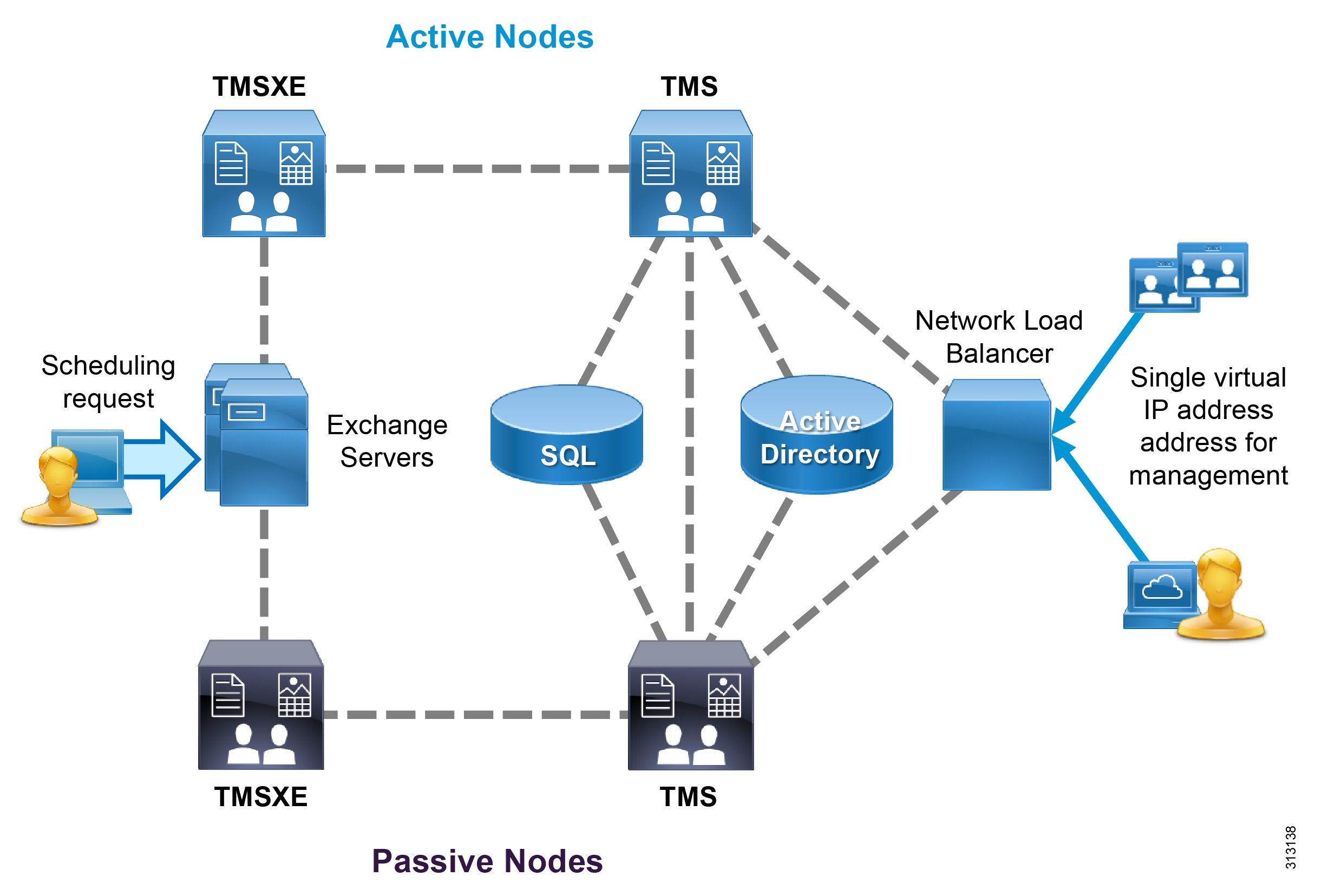
Cisco TelePresence Management Suite (TMS) runs on a Microsoft Windows server and utilizes the Microsoft SQL database to store information about users, controlled devices, and scheduled conferences. User profiles are imported from Microsoft Active Directory, and the permissions model allows for access control to various components and configured systems. Deploy Cisco TMS with Cisco TMSXE to provide Microsoft Exchange integration.
A single deployment of TMS is required for each organization. Leverage the integrated system navigator folder structure to organize all endpoints and infrastructure devices. Even multinational and global organizations can benefit from a single deployment of TMS to facilitate video connections.
Redundancy for TMS and its supporting extensions is different from other components in the Cisco Collaboration on-premises Preferred Architecture. TMS and its components operate in an active/passive model instead of clustering. A single instance of TMS consists of a Network Load Balancer, two servers hosting TMS, two servers hosting the TMSXE application, and the SQL database (Figure 9). The licensing for the instance is maintained in the SQL database, so separate licensing is not required for each node. Only one server for each application is active at any moment, with the web pages and services of the passive (inactive) node locked down to refuse all other incoming traffic. All servers must be members of the same domain.
Figure 9 Cisco TMS Redundancy Model
Deploy the Microsoft SQL database separately from the TMS server. The instance of SQL may be shared by other applications within the organization, and it should be a high-availability deployment in accordance with Microsoft's recommendations.
Support for Multiple Call Processing Sites
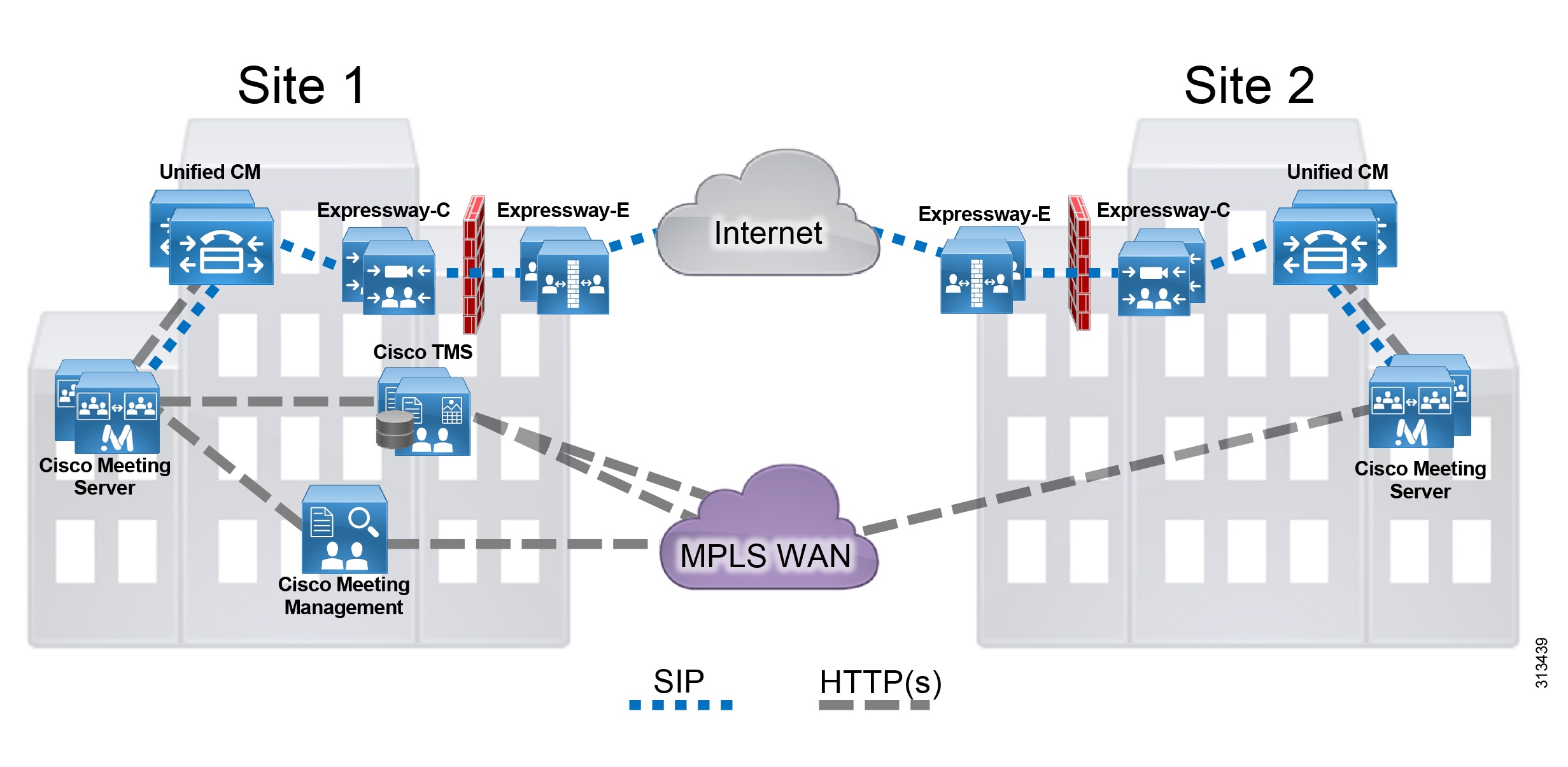
Organizations may choose to implement more than one Cisco Meeting Server cluster (Figure 10) for any of the following reasons:
- Administrative separation — This includes the need to keep users from different parts of the organization on separate infrastructures or to have different departments operate different parts of the communications infrastructure.
- Geographic footprint — Physical limitations such as excessive latency between endpoints and conferencing resources could degrade the user experience (for example, US users might not have a productive collaborative meeting if they use conferencing resources located in Europe).
However, when multiple Cisco Unified CM clusters are deployed, we recommend deploying a single Cisco Meeting Server cluster with one call bridge group dedicated for each Unified CM cluster. The call bridges within the group should be deployed in the same data center as the corresponding Unified CM cluster. Using a single Cisco Meeting Server cluster enables users to access the same conference using the same video address regardless of which Unified CM cluster they dial from.
Figure 10 Multiple Call Processing Sites with Conferencing
Managing Conferencing Resources
Cisco Meeting Management (CMM) is a mandatory component in a Cisco Meeting Server deployment that connects to Cisco Smart Licensing for license monitoring and management. CMM also provides administrators the ability to provision Cisco Meeting web app users so that users can join, create and manage their own meetings using a browser portal. Cisco Meeting Management also provides conference monitoring and management controls for Collaboration administrators and operators.
Benefits
This deployment provides the following benefits:
- Users have a consistent experience for launching and joining various types of conferences.
- A single conferencing platform provides on-premises audio and video conferencing.
- It provides users with real-time, high-definition video conferencing, including the ability to share content easily over a dedicated presentation channel.
- Cisco Meeting Management provides administrators the ability to manage conference resources, manage meetings and provision CMS web app users.
- Cisco TMS provides users with enhanced features such as directories and One Button To Push (OBTP) on controlled endpoints. It enables administrators to import user profiles from Microsoft Active Directory, which allow access control to various components and configured systems.
Collaboration Edge
Business demand for connectivity between organizations by leveraging the Internet has increased significantly over the past few years. For many organizations, this connectivity is a fundamental requirement for conducting day-to-day activities. Moreover, securely connecting mobile workers and remote sites to each other and to headquarters is critical functionality that enables organizations to accomplish their business goals. The Cisco Collaboration on-premises Preferred Architecture addresses these needs with the Collaboration Edge architecture shown in Figure 11.
Figure 11 Architecture for Collaboration Edge
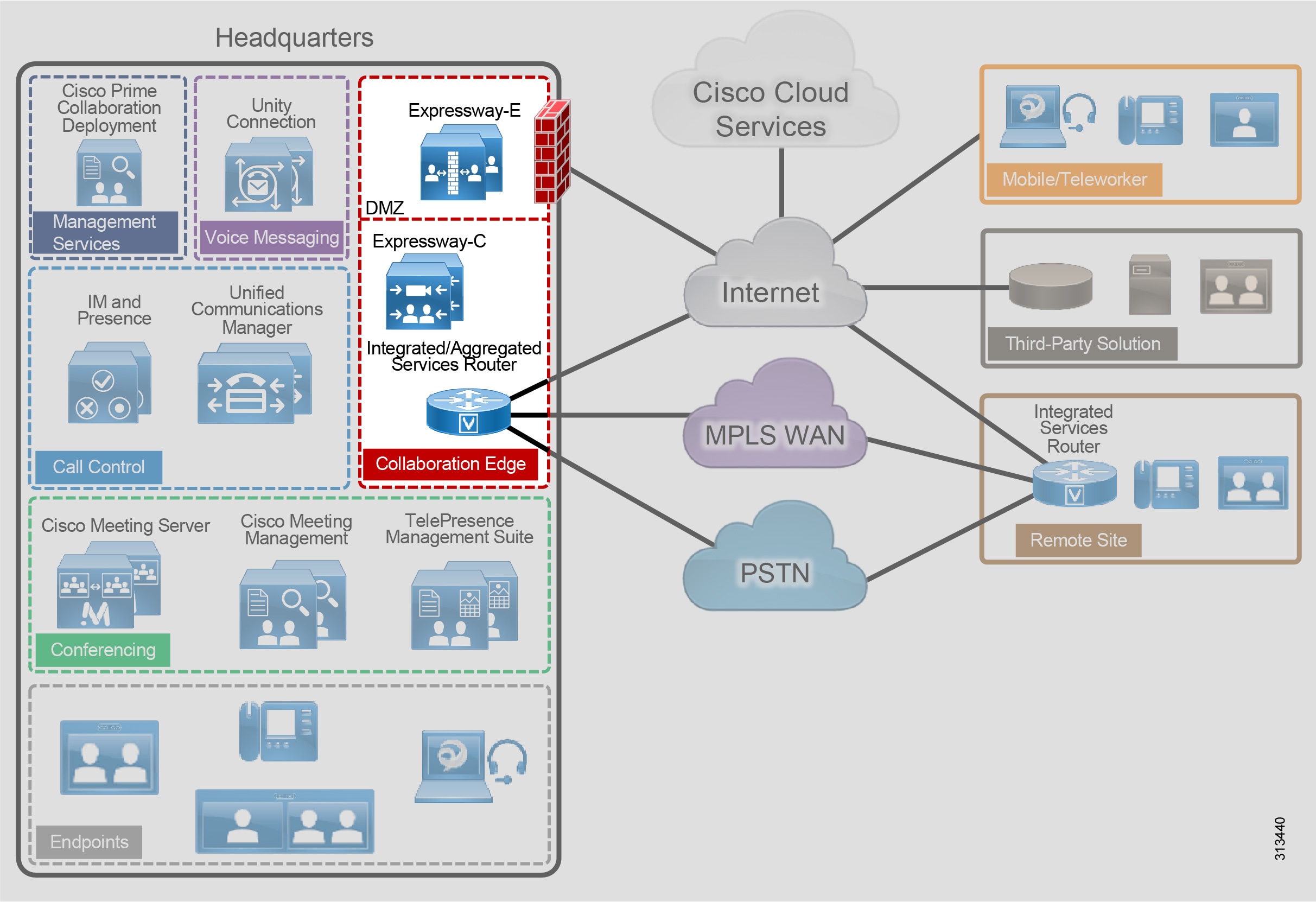
Table 8 lists the roles of the Collaboration Edge components in this architecture and the services they provide.
Recommended Deployment
We recommend the following Collaboration Edge solution for the Cisco Collaboration on-premises Preferred Architecture:
- Deploy a Cisco Expressway-C and Expressway-E server pair to enable remote Jabber and TelePresence video endpoint registrations, and IM and Presence. Deploy a separate Expressway-C and Expressway-E server pair for secure business-to-business connectivity through the firewall. Cluster both Expressway-C and Expressway-E servers in both pairs. If your deployment does not reach or exceed the scalability limit, you can deploy a single Expressway-C and Expressway-E cluster for both business-to-business and mobile and remote access applications.
- Deploy a Cisco ISR or ASR as the PSTN gateway, or enable Cisco Unified Border Element functionality on the Cisco ISR or ASR for voice connectivity from the organization's network to the service provider network through a SIP trunk.
- If full redundancy is not required, a single server pair (Expressway-C and Expressway-E) may be deployed.
- Deploy a Cisco ISR as the PSTN gateway.
- Deploy Expressway-C and Expressway-E if the remote site has local Internet connectivity and an Internet business-to-business architecture for video calls is required.
- For video-enabled sites, deploy Cisco TelePresence endpoints utilizing the Expressway-C and Expressway-E infrastructure at headquarters or another site.
- In addition, the Cisco Jabber client and a specific set of hardware voice and video devices can be used without VPN, regardless of the location of the endpoint (internal or external to the organization).
Cisco Expressway
Cisco Expressway provides secure firewall and NAT traversal for mobile or remote Cisco Jabber and TelePresence video endpoints (Figure 12), and it provides secure business-to-business communications (Figure 13). Cisco Expressway consists of two applications: Expressway-C and Expressway-E.
Deploy Cisco Expressway-C inside the network, and deploy Expressway-E in the demilitarized zone (DMZ) by connecting separate network ports on Expressway-E to the organization's network and to the DMZ.
Cisco fully supports a virtualized Expressway-E in the DMZ; however, a dedicated server can be deployed based on the company's security requirements.
Figure 12 Traversal for Endpoint Registrations Through Firewall with Expressway-C and Expressway-E
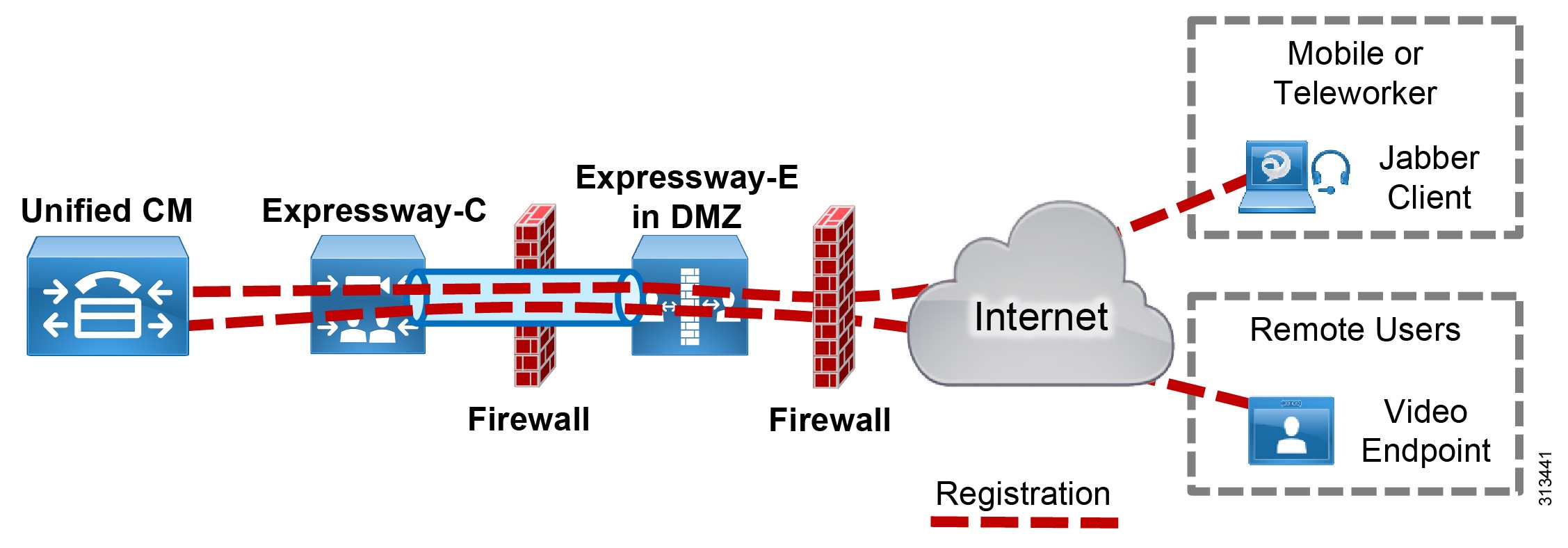
Figure 13 Traversal for Business-to-Business Calls Through Firewall with Expressway-C and Expressway-E

Place Expressway-C in the trusted network inside the organization. Deploy Expressway-C to:
- Function as a traversal client and establish a secure connection to Expressway-E through the firewall
- Establish secure or non-secure connection to Cisco Unified CM
- Integrate with an existing internal video network that uses H.323
- Enable business-to-business calls to external entities that communicate using SIP or H.323
- Provide interworking between H.323 and SIP protocols for H.323 business-to-business communications
- Enable mobile and remote access capabilities and call signaling for Cisco supported endpoints, directing them to Cisco Unified CM for SIP registration and/or the IM and Presence Service (See Table 5 for information on which endpoints support mobile and remote access.)
Because Expressway-E is reachable directly from the untrusted external network, it should be placed in a DMZ for security. The organization's firewall policies control communications to and from this server. Deploy Expressway-E to:
- Function as a traversal server and allow secure communications to and from Expressway-C
- Enable audio, video, and IM and Presence connections to other organizations using SIP or H.323 on the Internet
- Provide DNS SRV lookup service to resolve outbound calls and to receive inbound calls over the Internet
- Process registration and IM and Presence information from Cisco endpoints on the external network and use secure traversal communications to pass the information to Expressway-C
- Provide interworking between protocols (between SIP and H.323, and between IPv4 and IPv6) for business-to-business communications
PSTN Gateway
Because landlines and mobile phones use the PSTN for local and international calls, external connectivity to the PSTN from an organization's IP telephony network is a requirement (Figure 14).

Use a Cisco ISR or ASR with a time-division multiplexing (TDM) module as the PSTN gateway at headquarters. This configuration enables the gateway to implement media interworking for the organization's incoming and outgoing PSTN calls.
At remote sites, deploy a Cisco ISR for local PSTN connectivity using voice modules. For more information about Cisco ISR, see the data sheet.
Redundancy is achieved by deploying multiple ISRs or ASRs. Cisco Unified CM has the ability to route traffic to the closest available router.
If SIP trunks are used to connect to a service provider for voice calls, enable Cisco Unified Border Element (CUBE) functionality on the Cisco ISR that is deployed at headquarters, and deploy CUBE in the demilitarized zone (DMZ). Cisco Unified CM routes calls through SIP trunks to gateways, CUBE, or Cisco Expressway based on the dial plan. For dial plan recommendations, see the Call Control section.
Benefits
This deployment provides the following benefits:
- The Cisco ISR supports standards-based interfaces and various PSTN types, so it can be deployed globally.
- Instead of traditional PSTN interfaces, Cisco Unified Border Element functionality can be enabled on the Cisco ISR and ASR if a SIP trunk is used.
- The Cisco ISR and ASR can be used for WAN connectivity.
- Cisco Expressway provides calling, presence, instant messaging, voicemail, and corporate directory services for Cisco Jabber and TelePresence video endpoints.
- Cisco Expressway enables video communications between organizations, partners, and vendors over the Internet.
Voice Messaging
Voice messaging is considered to be a basic requirement and essential service for any collaboration deployment. Cisco Unity Connection enables users to access and manage voice messages from their email inbox, web browser, Cisco Jabber client, Cisco IP Phone, or TelePresence endpoint. The Cisco Collaboration on-premises Preferred Architecture includes Cisco Unity Connection to enable voice messaging for the collaboration solution (Figure 15).
Figure 15 Architecture for Voice Messaging

Table 9 lists the roles of the voice messaging components in this architecture and the services they provide.
Recommended Deployment
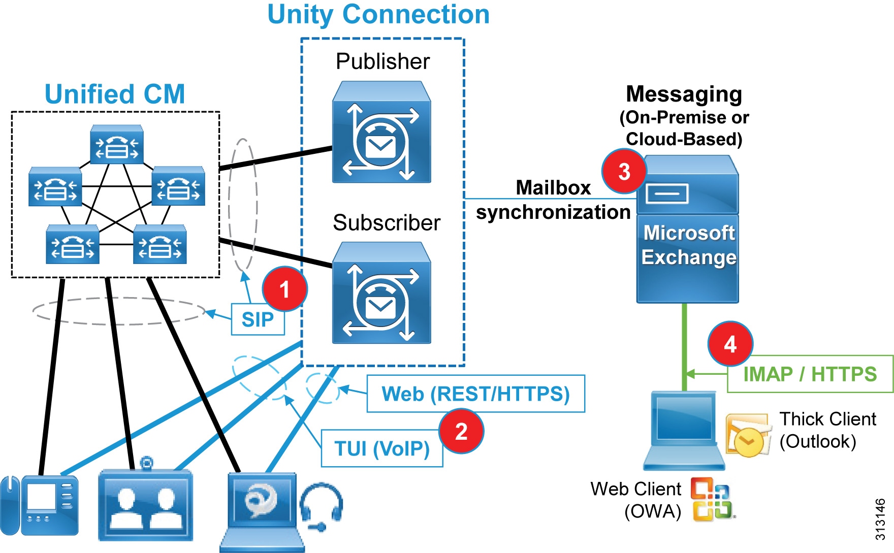
Cisco Unity Connection supports a cluster configuration in active/active mode to provide both high availability and redundancy. As depicted in Figure 16, a Unity Connection cluster consists of a maximum of two nodes, one publisher and one subscriber (#1). If one of the Unity Connection nodes fails, the other active node in the cluster handles all the calls and HTTP requests for the Unity Connection cluster. Each server in the Unity Connection cluster must have enough voice messaging ports to handle all calls for the cluster.
As shown in Figure 16, the integration between Cisco Unified CM and Unity Connection relies on SIP for communications (#1). In addition, hardware and software endpoints are able to access voice messaging services through VoIP communications or via REST-based HTTPS communications (#2). The voicemail pilot number designates the directory number that users dial to access their voice messages. Unified CM automatically dials the voice messaging number when users press the Messages button on their phone (VoIP). Visual Voicemail allows users to access voicemail from the graphical interface on the IP phone or Jabber client (HTTPS). Users can view a list of messages and play messages from the list. Users can also compose, reply to, forward, and delete messages. Each voicemail message displays data that includes the date and time when the message was left, urgency level, and message length.
Figure 16 Unified Messaging Architecture
In summary, we recommend deploying Cisco Unity Connection as follows:
- Deploy two Cisco Unity Connection servers for each Cisco Unified CM cluster to provide high availability and redundancy.
- Use SIP trunks to integrate Unity Connection with Unified CM. Configure two SIP trunks, one for each Unity Connection server in a pair.
- Import user information from the enterprise LDAP directory to Unity Connection. Each mailbox must have a unique voicemail number. Unity Connection supports both E.164 and + E.164 formats for the extension of an end-user account (user with a voice mailbox). Unity Connection also supports alternate extensions per user.
- Configure visual voicemail and unified messaging, including Single Inbox, and then enable users for appropriate voice message retrieval methods.
- Enable the speech-activated voice command interface to maximize productivity of mobile workers.
For more information about Cisco Unity Connection, refer to the product documentation.
Benefits
This deployment architecture provides the following benefits:
- Users can access the voicemail system and retrieve their voice messages by using their IP phones, mobile devices, and various email client applications with either a dialed number or a SIP URI.
- Cisco Unity Connection allows users to customize personal settings from a web browser.
- Cisco Unity Connection offers a natural and robust speech-activated user interface that allows users to browse and manage voice messages using simple and natural speech command.
Collaboration Management Services
System management and software licensing are important functions in a collaboration system environment. The Cisco Collaboration on-premises Preferred Architecture includes the following Cisco core management applications that are considered to be a basic requirement and foundational to any collaboration solution (Figure 17):
- Cisco Prime Collaboration Deployment — Assists with installation of applications.
- Cisco Smart Software Manager — Internet-based Cisco cloud service with web portal for managing collaboration user licenses
- Cisco Webex Cloud-Connected UC (CCUC) – Provides centralized on-premises application analytics and operations from Webex Control Hub.
Figure 17 Architecture for Collaboration Management Services
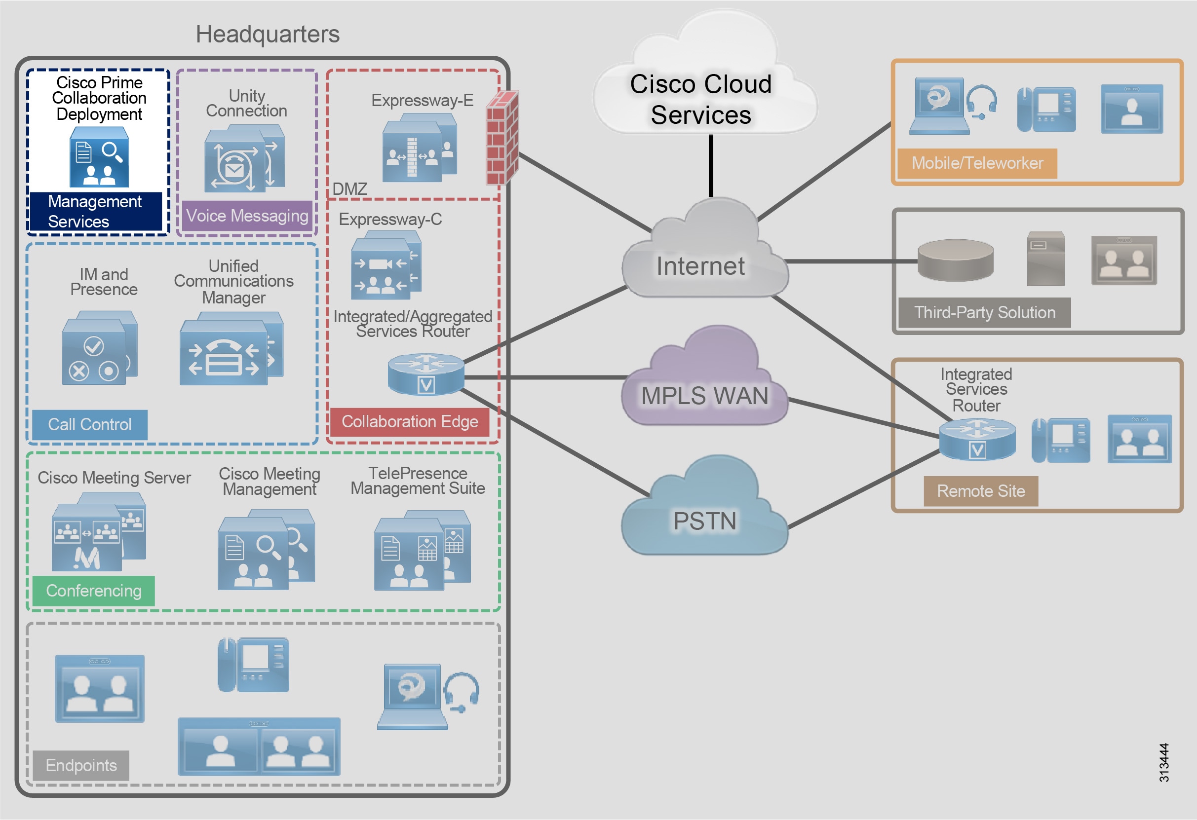
Table 10 lists the roles of the application components in this architecture and the services they provide.
Cisco Prime Collaboration Deployment
Cisco Prime Collaboration Deployment assists the administrator by automating many of the primary steps necessary to configure and install Cisco Collaboration applications.
Cisco Prime Collaboration Deployment supports the following applications in the Cisco Collaboration on-premises Preferred Architecture:
Recommended Deployment
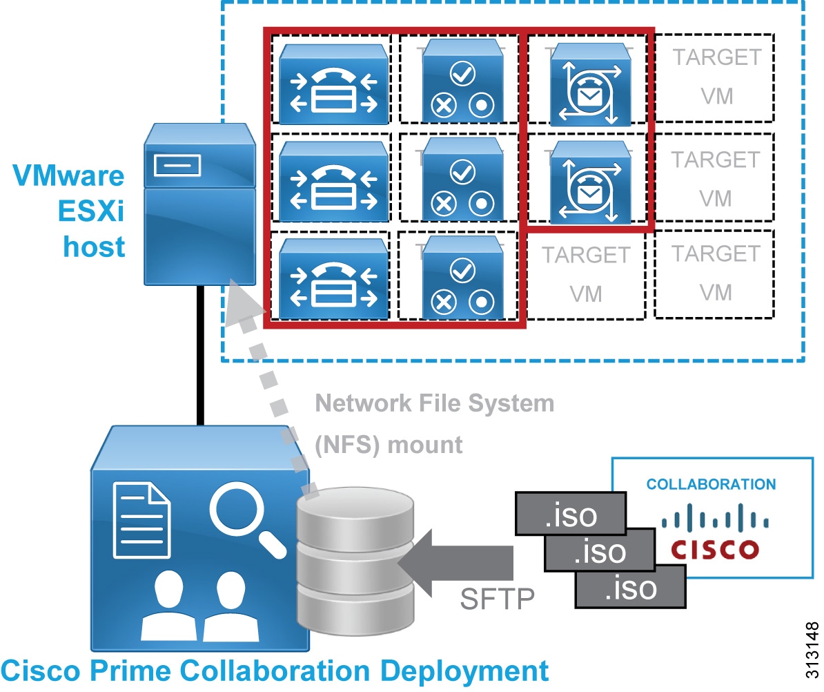
Figure 18 illustrates the following recommended architecture for Cisco Prime Collaboration Deployment:
- Install Cisco Prime Collaboration Deployment on a dedicated virtual machine (VM) and not co-resident with any other applications.
- Cisco Prime Collaboration Deployment uses the collaboration application installation ISO files (available from Cisco.com) to install and deploy the Collaboration applications (see Figure 18).
Figure 18 Architecture for Cisco Prime Collaboration Deployment
Benefits
Cisco Prime Collaboration Deployment provides the following benefits:
- Enables automated, unattended installation of ESXi-hosted collaboration application virtual machine server nodes
- Facilitates configuration of a common base platform and initial application settings for all collaboration application nodes, including:
–![]() Network services (time, domain name)
Network services (time, domain name)
Webex Cloud-Connected UC
Webex Cloud-Connected UC is a set of cloud services delivered by Webex and managed through Webex Control Hub that provides centralized and simplified on-premises collaboration application management and visibility.
Webex Cloud-Connected UC (CCUC) is designed for customers with on-premises collaboration deployments with Unified CM that want to move some of administrative workloads to the Webex cloud while still maintaining their on-premises calling workload.
CCUC appears as another workflow within Webex Control Hub and for deployed on-premises applications delivers in-depth analytics and system visibility including:
Recommended Deployment
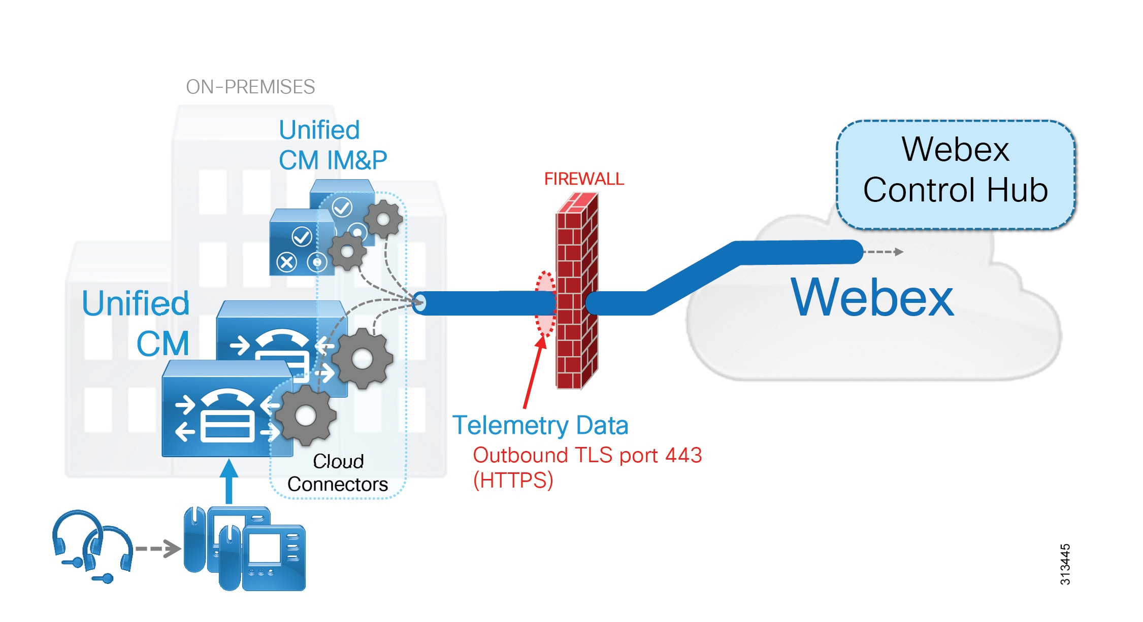
Figure 19 illustrates the following recommended architectural aspects of the CCUC deployment:
- CCUC cloud connectors run on each collaboration application node (in this case Unified CM).
- The CCUC cloud connector and related services collect system telemetry data including endpoint and headset utilization.
- Collected data is sent to Webex via an HTTPS connection initiated outbound from the UC infrastructure applications (in this case Unified CM). Telemetry data is encapsulated in HTTPS (TLS 1.2) and sent through the organization’s firewall and/or HTTPS proxy on port 443.
- Collected telemetry data is analyzed and reported to the customer administrator within Webex Control Hub.
Figure 19 Architecture for Webex Cloud-Connected UC
Benefits
Webex Cloud-Connected UC provides the following benefits:
- Webex Control Hub provides a single pane of glass for both cloud and on-premises UC management.
- Solution delivered with proxy-aware “cloud connectors” running on infrastructure collaboration application nodes.
- Lower total cost of ownership (TCO) as customer gains cost optimized insights and increased administrative productivity through automated workflows.
- Delivers analytics for broad business and operations actionable insights for collaboration products.
- Enables customer to maintain business-critical calling and media on-premises.
- Simplifies and augments monitoring and reporting features and workflows for Cisco on-premises UC collaboration deployments.
- Industry leading Webex security and privacy with disaster recovery and redundancy.
–![]() All data is encrypted at rest and in transit.
All data is encrypted at rest and in transit.
–![]() Webex Identity Services infrastructure is used to authenticate and authorize cloud connectors to a specific Webex Control Hub organization.
Webex Identity Services infrastructure is used to authenticate and authorize cloud connectors to a specific Webex Control Hub organization.
–![]() All the data sent by CCUC is outlined in the privacy data sheet maintained at the Trust Portal (trustportal.cisco.com).
All the data sent by CCUC is outlined in the privacy data sheet maintained at the Trust Portal (trustportal.cisco.com).
Webex Cloud-Connected UC is recommended in the Preferred Architectures as the platform of choice for application management and visibility. More features are planned and will release this year such as:
- Certificate management workflows. These workflows will provide the ability to manage (add, delete) certificates of all UC apps centrally, across multiple clusters
- Troubleshooting workflows. Gain actionable diagnostic insights and proactive troubleshooting workflows at the level of entire deployments to improve admin productivity
Cisco Smart Software Manager
The Cisco Smart Software Manager is an Internet-based web portal that provides simplified and flexible enterprise-wide management of software licensing. Cisco Smart Software Manager simplifies licenses and software activation as well as reconciliation of licenses across supported products, and it provides enterprise-level reporting of usage and entitlement. Cisco Smart Software Manager also supports deployments with multiple clusters.
Cisco Smart Software Manager supports the following applications in the Cisco Collaboration on-premises Preferred Architecture:
Recommended Deployment
We recommend direct or proxy communications between the web-based Cisco Smart Software Manager and your on-premises Unified CM and Unity Connection, Cisco Meeting Management and Expressway nodes. This does require outbound HTTPS communications from collaboration application’s nodes through your organization’s firewall to the web-based Cisco Smart Software Manager service. If your organization does not enable direct outbound web communications, you should direct cluster publisher nodes to a standard HTTP/HTTPS proxy server within your organization to enable firewall traversal and access to the web-based Cisco Smart Software service.
Security
As with almost everything today, it is important to secure your collaboration deployment. A collaboration deployment is subject to threats such as denial of service, unauthorized access, toll fraud, and eavesdropping. It is important to protect your collaboration deployment against these threats. Take a layered security approach by securing various network levels: secure physical access, network infrastructure, collaboration applications, and collaboration endpoints (Figure 20).
Solely following the recommendations in this section does not guarantee a secure environment, nor will it prevent all penetration attacks on a network. You can achieve reasonable security by establishing a good security policy, following that security policy, staying up-to-date on the latest developments in the hacker and security communities, and maintaining and monitoring all systems with sound system administration practices.
Figure 20 Secure All Components of the Enterprise Collaboration Preferred Architecture

Recommended Deployment
We recommend the following general security practices for the Cisco Collaboration on-premises Preferred Architecture:
- Secure the infrastructure by protecting physical access, and secure the IP network.
- Use hardening techniques to secure all devices, including servers and endpoints.
- Protect your deployment against toll fraud.
- Simplify certificate management by having certain certificates signed by a certification authority (CA).
- Do not disable native security features. For example, do not disable Security By Default in Cisco Unified CM.
- Encrypt SIP trunks, HTTP connections, and other server-to-server links.
- To protect sensitive voice and video communications, enable mixed-mode on Cisco Unified CM and enable encrypted signaling and media for endpoints. This is especially important if your network is not entirely trusted and secure.
Secure Infrastructure Recommendations
- Secure your infrastructure; it is the foundation of your collaboration deployment.
- Protect physical access to your premises, network, endpoints, and especially the servers.
- Protect your network with firewall and Intrusion Prevention System (IPS) devices.
- Implement security features at Layer 2 and Layer 3 for your network. For example, protect access to your network with 802.1X, and protect your DHCP server with DHCP Snooping and Dynamic ARP Inspection.
- Implement network segmentation by having a separate voice/video VLAN for hardware endpoints and a data VLAN for multipurpose devices such as mobile phones and laptops running Jabber.
- With Cisco Unified Border Element deployed at the network edge, configure the Unified Border Element protection mechanisms against telephony denial of service (TDoS) and configure access control lists (ACLs).
Toll Fraud Recommendations
On Cisco Unified CM, several mechanisms can be used to prevent toll fraud. Partitions and calling search spaces (CSS) provide segmentation and access control to the directory number that can be called or the device or line that is placing the call. As a best practice, apply the most restrictive class of service possible (for example, no access to PSTN routes for calls coming in from the PSTN) based on partitions and calling search spaces. Other mechanisms can also be used, such as time-of-day routing, enabling the Block OffNet to OffNet Transfer service parameter, forced authentication code (FAC), and route filters.
On Cisco Expressway-E, use Call Processing Language (CPL) rules to block fraudulent attempts.
On Cisco Unified Border Element, configure protection mechanisms against toll fraud; for example, configure an IP trust list and explicit incoming and outgoing dial peers.
Certificate Recommendations
Simplify certificate management with certification authority (CA) signed certificates. By default, server certificates are self-signed. To establish trust with a service based on a self-signed certificate, the self-signed certificate must be imported into the trust store of all entities requiring secure connections to the service. If the certificate are not imported, the communication can fail or warning messages about the certificate might appear, as with Jabber for example. Importing certificates can be handled if the set of communicating parties is small, but it becomes more difficult for large numbers of communication peers. For this reason, we recommend having some of the certificates signed by a certification authority (CA) and extending trust to the CA. This is especially important for certificates such as the Tomcat certificates for Cisco Unified CM with IM and Presence Service and Cisco Unity Connection, as well as the XMPP certificate for IM and Presence.
For Cisco Expressway-E servers, use certificates that are signed by a public CA.
Use multi-server certificates wherever possible, especially for the Cisco Unified CM and Unified CM IM and Presence Tomcat certificates. Multi-server certificates allow the administrator to assign a single certificate for a given service across multiple servers in a cluster in order to further simplify certificate management.
On the endpoints, in general, two types of certificates are available: Manufactured-Installed Certificate (MIC) and Local Significant Certificate (LSC). Endpoint certificates are used for encryption of the signaling and media and for the optional encryption of TFTP phone configuration files. We recommend using LSC certificates instead of MIC certificates.
Encryption Recommendations
Provide encryption for the following:
SIP trunks connect Cisco Unified CM with other servers such as Cisco Unity Connection, IM and Presence, Cisco Meeting Server, Cisco Unified Border Element, business-to-business Collaboration Edge, and voice gateways.
Use HTTPS instead of HTTP for all application connections. For example, use HTTPS with Extension Mobility.
With a Cisco Unified CM multi-cluster deployment, also enable encryption for:
- Intercluster Lookup Service (ILS)
- Location Bandwidth Manager (LBM)-to-LBM communication between clusters
To protect sensitive voice and video communications, enable endpoint encryption for signaling and media. This is especially important if your network is not entirely trusted and secure. This requires enabling mixed-mode in Cisco Unified CM. With mixed mode, you can select which endpoints are configured to use signaling and media encryption and which are not.
Benefits
These security recommendations provide the following benefits:
- Your collaboration deployment is more secure if the physical access is protected and the IP network is secured.
- By protecting network access to servers and phones, you make it more difficult to compromise them and get access to other devices in the deployment.
- By implementing toll fraud protection mechanisms, you can prevent unauthorized access to your telephony system, data network, and PSTN lines.
- By signing certain certificates with a CA, you make it easier to manage the certificates and, more importantly, you increase security by avoiding scenarios where end-users must accept certificates on their computing device, which most end-users do without verifying the authenticity of the certificates.
- Several secure features are implemented by default. For example, with Cisco Unified CM, phone configurations and firmware loads are signed so that it becomes more difficult to compromise the phones by loading malicious configurations or firmware.
- Encryption protects against eavesdropping and protects the privacy of voice and video calls. It also protects against tampering. By encrypting communications between all devices, including the endpoints, you can achieve end-to-end encryption.
Bandwidth Management
Bandwidth management is about ensuring the best possible user experience end-to-end for all voice and video endpoints, clients, and applications in the Collaboration solution. The Cisco Collaboration on-premises Preferred Architecture provides a holistic approach to bandwidth management that incorporates an end-to-end Quality of Service (QoS) architecture, call admission control, and video rate adaptation and resiliency mechanisms to ensure the best possible user experience for deploying pervasive video over managed and unmanaged networks.
Bandwidth Management Architecture for Collaboration
With recent increases in the number of interactive applications – particularly voice and video applications – real-time services are often required from the network. Because these resources are finite, they must be managed efficiently and effectively. If the number of flows contending for such priority resources were not limited, then as those resources become oversubscribed, the quality of all real-time traffic flows would degrade, eventually to the point of becoming useless. To address this requirement the Cisco Collaboration on-premises Preferred Architecture provides a strategy that leverages "intelligent" media techniques, QoS, and admission control to prevent real-time applications and their related media from oversubscribing the network and the bandwidth provisioned for those applications, thus ensuring efficient use of bandwidth resources.
Figure 21 illustrates the approach to bandwidth management used in the Cisco Collaboration on-premises Preferred Architecture. This approach consists of the following phases:
- Identification and classification — Refers to concepts of trust and techniques for identifying media and signaling for trusted and untrusted endpoints. It also includes the process of mapping the identified traffic to the correct DSCP markings to provide the media and signaling with the correct per-hop behavior end-to-end across the network for both trusted and untrusted endpoints.
- Queuing and scheduling — Consists of general WAN queuing and scheduling, the various types of queues, and recommendations for ensuring that collaboration media and signaling are correctly queued on egress to the WAN.
- Provisioning and admission control — Refers to provisioning the bandwidth in the network and determining the maximum bit rate that groups of endpoints will utilize. This is also where call admission control can be implemented in areas of the network where it is required.
- Monitoring, troubleshooting, and optimization — Ensures the proper operation and management of voice and video across the network. Cisco Prime Collaboration offers a suite of tools to perform these functions.
Figure 21 Architecture for Bandwidth Management
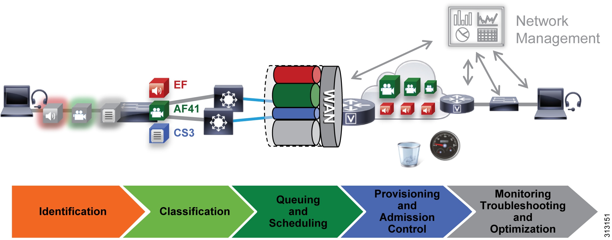
The concepts applied to the bandwidth management strategy illustrated in Figure 21 include:
- A self-regulating video network
- Prioritization of all audio streams throughout the network
- Creation of a class of video endpoints that use available bandwidth opportunistically
The following sections describe these concepts briefly.
A self-regulating video network leverages intelligent media techniques and rate adaptation along with proper provisioning and QoS to allow the video endpoints to maximize their video resolution during times when video bandwidth is not fully utilized in the network and to rate adapt or throttle down their bit rate to accommodate more video flows during the busy hour of the day.
Prioritized audio for both audio-only calls and audio of video calls ensures that all audio is prioritized in the network and is thus not impacted by any loss that might occur in the video queues. Prioritizing voice from all types of collaboration media ensures that, even during times of extreme congestion when video is experiencing packet loss and adjusting to that loss, the audio streams will not suffer packet loss and will enable the users to have an uninterrupted audio experience.
Opportunistic video allows for a group of video endpoints to be strategically marked with a lower class of video, thus allowing them to use available bandwidth opportunistically for optimal video resolution during times when the network is less busy and more bandwidth is available. Conversely, the lower class of video endpoints can throttle down their video bit rate more aggressively than the prioritized class of video during times of congestion when the network is in its busy hour. This concept of opportunistic video, coupled with prioritized audio, maintains an acceptable video experience while simultaneously ensuring that voice media for the opportunistic video calls is not compromised. This, of course, applies to the managed network, since an unmanaged network such as the Internet is not QoS-enabled and thus provides no guarantees with regard to packet loss. Nevertheless, the media resiliency and rate adaptation mechanisms also attempt to ensure that media over unmanaged networks has the best possible quality in the face of packet loss, delay, and jitter.
Recommended Deployment
- Identify traffic based on trusted and untrusted devices.
- Classify and mark traffic at the access switch edge.
–![]() Mark all audio with Expedited Forwarding class EF (includes all audio for voice-only and video calls).
Mark all audio with Expedited Forwarding class EF (includes all audio for voice-only and video calls).
–![]() Mark all critical desktop and room system video with an Assured Forwarding class of AF41.
Mark all critical desktop and room system video with an Assured Forwarding class of AF41.
–![]() Mark all Jabber, Mobile and Remote Access (MRA), and Edge video with an Assured Forwarding class of AF42.
Mark all Jabber, Mobile and Remote Access (MRA), and Edge video with an Assured Forwarding class of AF42.

Note This creates a class of video endpoints and video call flows that are opportunistic in nature. (For more details, see Opportunistic Video.) If AF42 marking and scheduling are not possible due to limitations on customer edge equipment or other reasons, then AF41 can be used for all video traffic. If that is the case, then the benefits of Opportunistic Video will be minimized. With only AF41 marking, all video traffic will compete equally for resources and rate adapt based on utilization in a self-regulating video network.
–![]() Configure QoS on all media originating and terminating applications and MCUs across the solution.
Configure QoS on all media originating and terminating applications and MCUs across the solution.
- Apply simplified WAN Edge policies for identifying, classifying, marking, and queuing collaboration traffic:
Benefits
This deployment provides the following benefits:
- Employs prescriptive recommendations to simplify deployment with a simplified QoS architecture
- Makes more efficient use of network resources
- Supports mobile and multi-media Collaboration devices
- Takes into account "unmanaged" network segments (Internet)
- Is "future-proof" — facilitates introduction of new services, features, and endpoints
- Provides a self-regulating video network
Contact Cisco
- Open a Support Case

- (Requires a Cisco Service Contract)
 Feedback