- Executive Summary
- Solution Overview
- Solution Reference Architecture
- Solution Components
- Cisco Ultra-Reliable Wireless Backhaul Installation, Configuration, and Design Considerations
- Meraki MR Installation, Configuration, and Design Considerations
Digital Divide
Executive Summary
The Covid-19 global pandemic has impacted our daily lives in many significant ways. Communities and schools have had to change their operations to accommodate the new social distancing recommendations. Seemingly overnight, many people lost their jobs, others started working from home, and students were required to study at home. While the adjustments have been difficult for everyone, lower-income households are particularly affected because less access to reliable and fast Internet in their home impedes the ability to learn, work, and find jobs.
In a recent Pew Research study ( https://www.pewresearch.org/fact-tank/2020/09/10/59-of-u-s-parents-with-lower-incomes-say-their-child-may-face-digital-obstacles-in-schoolwork), roughly six-in-ten parents with lower incomes said it’s likely their homebound children face at least one digital obstacle to doing their schoolwork. 43% of these parents reported that their children must use a cellphone to complete their homework. This is far from ideal. Compounding the issue, 40% reported that the children have to use public Wi-Fi to access the Internet because the connection at home is unreliable.
This “digital divide” between upper- and lower-income communities can be addressed by existing technology in connected communities. The Cisco Digital Divide with extended wireless connectivity has been developed as a response to this situation. It is a total solution that enables secure and fast Wi-Fi to any household, helping schools and communities bridge this digital divide.
Scope of this document
This Cisco Reference Design (CRD) guide provides design guidance and describes best practices to implement the Digital Divide solution. Configuration examples and site survey results captured in this document are collected from a customer proof of value (PoV) testbed. The test results from the PoV testbed can be shared under a non-disclosure agreement (NDA) upon request. This guide focuses on the Cisco Meraki access point; other Cisco outdoor and industrial access points can also be applied to the solution, but that is outside scope of this document.
References
For associated deployment and implementation guides and related product data sheets refer to the following:
Cisco Digital Divide Solution Overview: https://www.cisco.com/c/en/us/products/collateral/wireless/guide-c22-744789.pdf
Cisco Ultra-Reliable Wireless Backhaul: http://www.cisco.com/go/wirelessbackhaul
Cisco Meraki outdoor wireless access point: https://meraki.cisco.com/products/wi-fi
Cisco Catalyst Rugged Series Industrial Ethernet Switches: https://www.cisco.com/c/en/us/products/switches/industrial-ethernet-switches/index.html
Cisco Umbrella: https://umbrella.cisco.com
Best Practice Design – MR Wireless: https://documentation.meraki.com/Architectures_and_Best_Practices/Cisco_Meraki_Best_Practice_Design/Best_Practice_Design_-_MR_Wireless
Meraki MR76 and MR86 Installation Guides: https://documentation.meraki.com/MR/MR_Installation_Guides/MR76_Installation_Guide
https://documentation.meraki.com/MR/MR_Installation_Guides/MR86_Installation_Guide
Cisco Meraki and Umbrella Integration: https://documentation.meraki.com/MR/Other_Topics/Cisco_Meraki_and_Umbrella_Integration_-_MR_Advanced%2F%2FUpgrade_License
Cisco Connected Communities Infrastructure (CCI): https://cisco.com/go/connected-communities-infrastructure
Cisco IoT Solutions Design Guides: https://www.cisco.com/go/iotcvd
Document Organization
The following table describes the sections in this document:
|
|
|
|---|---|
The solution including challenges, use cases, and key benefits. |
|
Describes core components of the solution architecture including Cisco Ultra-Reliable Wireless Backhaul, Meraki Wi-Fi access network, and Cisco Industrial Ethernet (IE) switch |
|
List of the hardware, software, license, and accessories of the solution |
|
Cisco Ultra-Reliable Wireless Backhaul Installation, Configuration, and Design Considerations |
Provides best practice and design consideration for deploying Cisco Wireless Backhaul |
Meraki MR Installation, Configuration, and Design Considerations |
Provides best practice and design consideration for deploying Cisco Meraki Access Point |
Provides best practice and design consideration for deploying Cisco Industrial Ethernet Switch |
|
Discuss the best practice to implement security for this solution |
|
Introduction to CCI Solution and mass scale infrastructure for city use cases |
|
Solution Overview
The Cisco Digital Divide with Extended Wireless Connectivity design provides a total solution to bridge the gap for the digital divide. It brings together Cisco Ultra-Reliable Wireless Backhaul radios, Cisco Industrial Ethernet (IE) switches, Cisco Meraki outdoor access points, and integrated security to extend any fiber or broadband network, such as one from a school, to targeted areas or specific homes in the community. The result is reliable and secure Internet access.
Cisco is uniquely positioned to help build the bridge to securely connect all students and homes. The solution offers:
■![]() Cost-effective operations: Uses existing network infrastructure and Internet services to extend connectivity to students and families in their home. This eliminates additional operating fees, as no broadband LTE-based services are required.
Cost-effective operations: Uses existing network infrastructure and Internet services to extend connectivity to students and families in their home. This eliminates additional operating fees, as no broadband LTE-based services are required.
■![]() Cisco Secure: Cisco’s industry-leading security provides the capabilities and policies to protect against cyber risk and control the data that students access.
Cisco Secure: Cisco’s industry-leading security provides the capabilities and policies to protect against cyber risk and control the data that students access.
■![]() Simple and fast deployment: A streamlined, complete solution from Cisco speeds deployment.
Simple and fast deployment: A streamlined, complete solution from Cisco speeds deployment.
■![]() Improved remote learning, working, and quality of life: Provides the needed reliability and bandwidth speeds in the home to bridge the digital divide, creating parity across the student body and the community.
Improved remote learning, working, and quality of life: Provides the needed reliability and bandwidth speeds in the home to bridge the digital divide, creating parity across the student body and the community.
■![]() Control: Offers the flexibility to deploy the service by household or by area to benefit those who need access the most. It also enables control over the data that students can access.
Control: Offers the flexibility to deploy the service by household or by area to benefit those who need access the most. It also enables control over the data that students can access.
■![]() Ability to lower costs further with public funding: Federal and local governments are offering programs to fund all or part of projects to bridge the digital divide. For example, the U.S. CARES Act (Coronavirus Aid, Relief, and Economic Security Act) opened up a $30.75 billion Education Stabilization Fund to assist K-12 schools with the pandemic. Look for what is available in your area.
Ability to lower costs further with public funding: Federal and local governments are offering programs to fund all or part of projects to bridge the digital divide. For example, the U.S. CARES Act (Coronavirus Aid, Relief, and Economic Security Act) opened up a $30.75 billion Education Stabilization Fund to assist K-12 schools with the pandemic. Look for what is available in your area.
■![]() Readiness for the future: Leverage the solution to create a secure, multiservice, and scalable network infrastructure that is suitable to support other applications across the school or community.
Readiness for the future: Leverage the solution to create a secure, multiservice, and scalable network infrastructure that is suitable to support other applications across the school or community.
Solution Reference Architecture
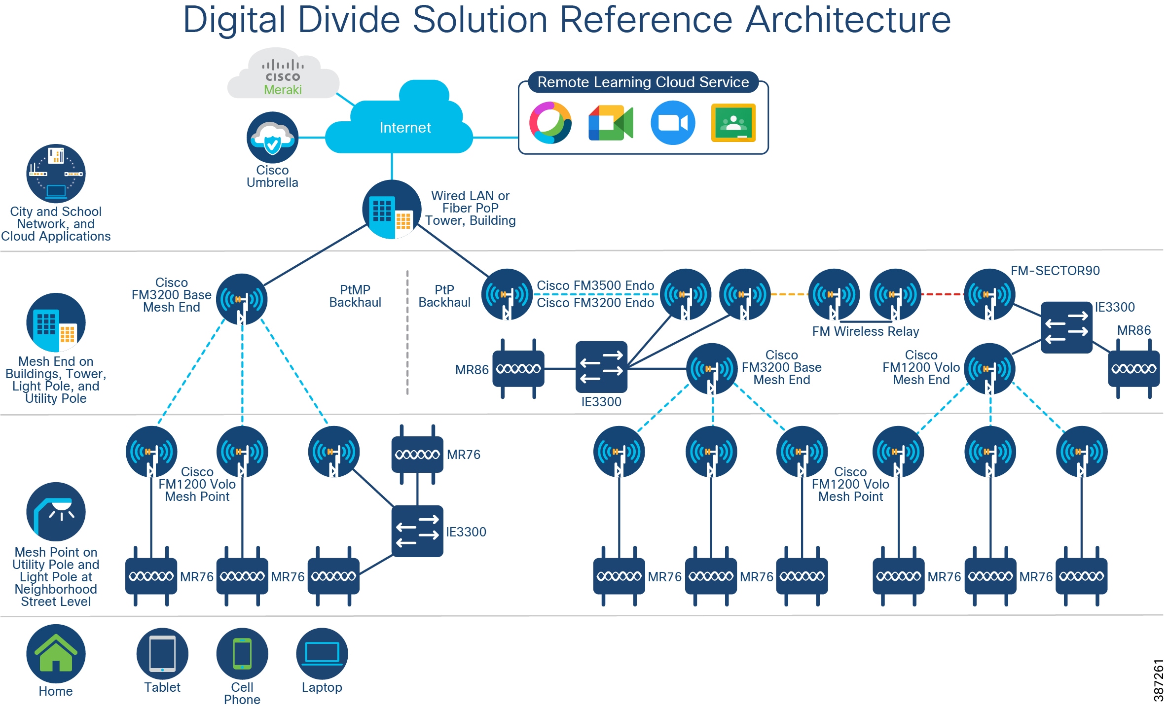
As illustrated in Digital Divide Solution Reference Architecture, the Cisco Digital Divide solution reference architecture includes the key components: Meraki outdoor access point MR76 or MR86, Cisco Industrial Ethernet switch IE3300, Cisco wireless backhaul radios, and Cisco Umbrella. Cisco wireless backhaul extends network connectivity into neighborhoods where reliable Wi-Fi is very limited. The backhaul connection is either terminated at a school headend network or connected to the Internet point of presence (POP) provided by an Internet service provider (ISP). The Meraki outdoor access point then delivers the highest performance and the most secured Wi-Fi access to the end users. When multiple devices are required at a particular location to meet the coverage and performance requirement, a ruggedized Cisco industrial ethernet switch can be used to provide the necessary connectivity to each of those devices.
Figure 1 Digital Divide Solution Reference Architecture
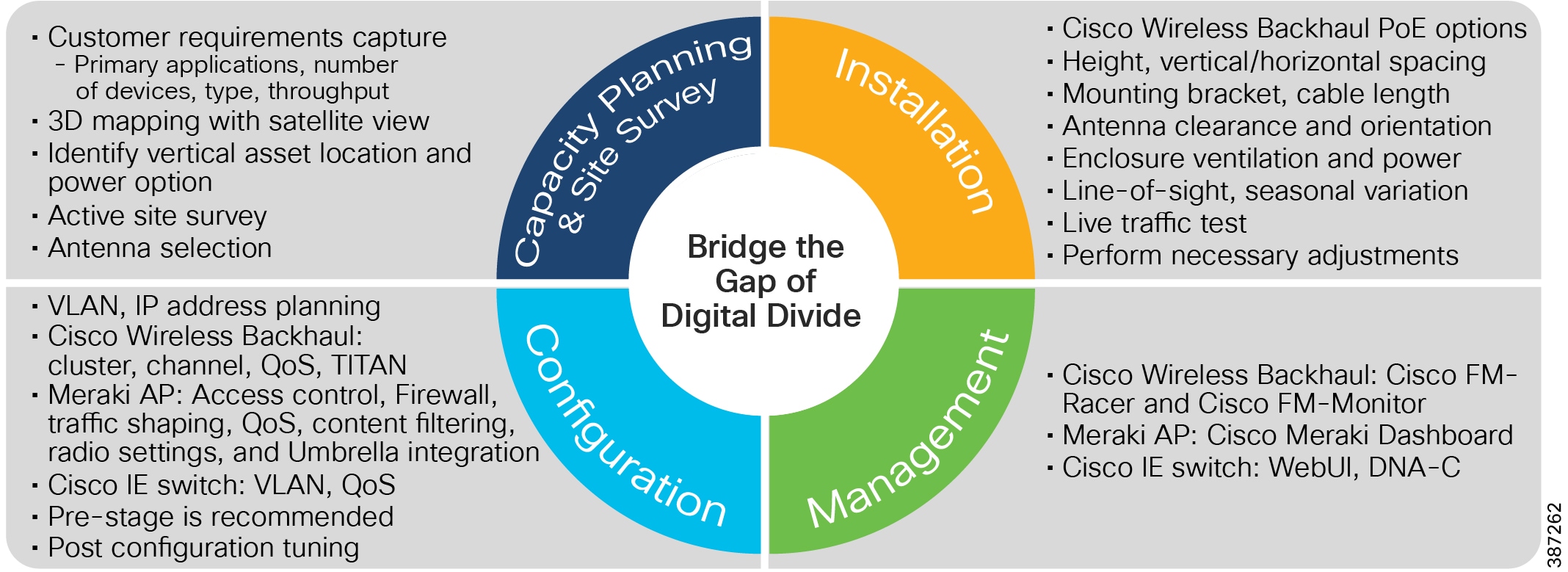
This reference design guide presents the best design practice to guide a successful solution deployment. Digital Divide Solution Deployment Workflow presents the basic deployment workflow that includes: capacity planning and site survey, installation, configuration, and management. The best practice and design considerations of each workflow have been discussed in detail in subsequent sections of this guide.
Figure 2 Digital Divide Solution Deployment Workflow
Solution Components
The key solution components of the Cisco Digital Divide solution for students and communities are listed in Table 2. Refer to Appendix A for detailed sample BoM including product IDs.
Table 2 Digital Divide solution components
Cisco Ultra-Reliable Wireless Backhaul Installation, Configuration, and Design Considerations
The key to a wireless backhaul solution is Cisco Ultra-Reliable Wireless Backhaul technology. This patented wireless technology enables a loop-free, scalable, and flexible mesh topology that will enable a school or city to extend their network into residential areas without the need for installing fiber. This flexibility enables point to point, point to multi-point, and mesh wireless links to coexist in the topology without the use of a dedicated wireless controller.
This is accomplished by designating radios as Mesh Ends or Mesh Points. A Mesh End is grouped with a number of Mesh Points and these form a cluster. These clusters can be grouped based on physical location or throughput requirements.
The wireless radios recommended for this type of deployment are the Cisco FM1200 Volo and the Cisco FM3200 Base. In cases where a high-speed point-to-point link is needed, the Cisco FM3500 Endo is a good choice because of its higher throughput and wide range of antenna choices, including omni-directional, panel, and dish. The software features are also modularized to keep costs lower depending on the needed feature set and throughput requirements. Some example wireless deployments are shown in Wireless deployments.
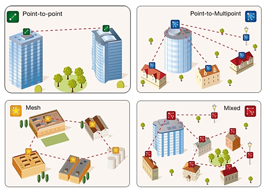
Hardware and Software
The Ultra-Reliable Wireless Backhaul radios designed for this outdoor mesh network are the FM3200 Base and FM1200 Volo. Each radio provides modulation rates up to 300Mbps and actual throughput up to 150Mbps depending on RF conditions and licensing.
The FM3200 Base is designed to be at the headend location or used as a hub device because of its wide 120-degree horizontal beamwidth antenna and ability to use 48V PoE. The FM3200 Base is typically designated as a Mesh End.
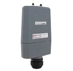
The FM1200 Volo has a narrower 33-degree horizontal beamwidth antenna and can be pointed back to the FM3200 Base or another FM1200 Volo depending on the network deployment. It is typically deployed as the attachment point for an end device which in this design, is a Cisco Meraki wireless access point, or multiple access points via a Cisco IE switch.
In this configuration, the FM1200 Volo is configured as a Mesh Point. This combination of Mesh Ends and Mesh Points allows the wireless backhaul to be scalable and flexible.
|
|
|
|
|---|---|---|

|
|
|
The throughput and feature set of the radio are determined by the software licenses, called plugins, which are installed on the radios. The FM1200 Volo offers more granular throughput choices (5,10,30,60,100Mbps) compared to the FM3200 Base (15,30,60,150Mbps) making it a better choice for endpoint devices. Throughput can be managed deterministically which leads to better network capacity and link budget planning. Additionally, VLAN and encryption can be added separately if needed.
In cases where a FM3500 Endo is used to create a backhaul link, a separate antenna is required. The antenna choice is based on the coverage area needed. If multiple radios are on a tower to provide 360-degree coverage, the correct antennas provide a narrower beamwidth; different frequencies can also be configured with the radio to prevent interference with a neighboring radio. If a longer range is desired, a higher gain antenna can be used. The appropriate antenna can be selected depending on the spread, distance, elevation, and degree of radio coverage required. In general, directional antennas are good for point-to-point topology, sector and horn antenna are suitable for radios that have a wide spread. With symmetric horizontal and vertical beamwidth, a horn antenna is a good choice when the radio elevations vary drastically.
Site Planning
When planning to build and install an Ultra-Reliable Wireless Backhaul network in a city or residential area, the design and product choices are critical. The locations of buildings and trees and even access to power will dictate the choice and placement of network devices. The decision to add a network switch at a radio location will also impact the power requirements, services supported, and physical installation parameters. This is why a site survey is critical to the success of the project. This guide is not designed to replace a professional site survey but rather give some guidelines for estimating where equipment can be placed in relation to the area being served.
Depending on whether the wireless traffic will be backhauled to a school network directly or a common infrastructure point (library, town hall, service provider), it is important to have a satellite view showing this wireless backhaul location in relation to the area where service will be provided. This service area could be a neighborhood block or individual houses. Using the features provided by Google Earth, Google Maps, or some other mapping tool, the wireless backhaul location and service areas can be outlined, and the distances computed. It is important to reference a 3D mapping tool to account for buildings, trees, or large changes in elevation.
With the map available and all the buildings marked, or the area outlined, it is necessary to determine the locations of any existing wired backhaul or wireless deployments. An existing wired backhaul could potentially be leveraged to provide an optimized hybrid solution while an existing wireless deployment may have to be worked around to reduce interference. The location of utility poles with power will also determine where equipment can be placed or whether new power must be added to cover an area.
When determining where to place the radios, it is necessary to know the estimated throughput at a given distance from the radio. These numbers are taken from the product datasheets and are given as a guideline only. The actual site survey will determine what numbers can be achieved.
Table 6 Cisco FM3200 Base throughput vs. distance
|
|
|
|
|
|
|
|
|
|
|
|
|
|
|
|
|
|
|
|
|
|
|
|
Table 7 Cisco FM1200 Volo throughput vs. distance
|
|
|
|
|
|
|
|
|
|
|
|
|
|
|
|
With the 2D and 3D map available and the estimated throughput numbers, a rough plan can be outlined for the placement of the radios. This plan will form the basis of a predictive site survey.
As stated before, a FM3200 Base configured as a Mesh End will connect to a number of FM1200 Volos configured as Mesh Points. Because the throughput on each Mesh Point is limited by the plugin installed, a cluster of radios can include the number of Mesh Points that are within RF range of the Mesh End and do not exceed the throughput limits of that Mesh End. For example, if each FM1200 Volo is configured with a 10 Mbps throughput plugin, a FM3200 Base could support up to 15x FM1200 Volos given the 150 Mbps maximum throughput. With a lower throughput plugin on the FM1200 Volo, more can be supported up to the best practice recommendation of 20 radios per cluster. If the Mesh Points in a given RF area exceed the throughput limit of the Mesh End or the recommended 20 radio limit, another cluster can be created with another Mesh End on a different frequency.
With this in mind, a school or other city building may have numerous FM3200 Base radios installed to provide coverage all around depending on the service area. Each radio will have to be oriented to reach the FM1200 Volos installed in the service area. When determining where to put the FM1200 Volo, numerous factors must be considered. To minimize cabling runs or the need for conduit between the FM1200 Volo and the Meraki access point, mounting them on the same pole is recommended. The FM1200 should be mounted high enough to have good line of sight to the other end of the backhaul radio, while Meraki access point should be mounted as close as possible to the same level as the coverage area and high enough to prevent vandalism. In the case of a city deployment, this may be a utility pole with power already in place. If it is a school deployment, there may not be access to a utility pole or the pole may not be close enough to the resident’s house or apartment. In that case, the radios may need to be installed in a safety enclosure and installed directly on or near the house depending on restrictions from a Homeowner’s Association or landlord if the house is being rented.
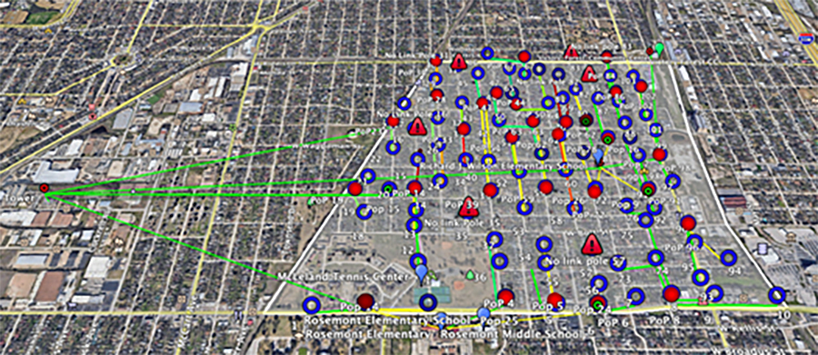
Below is an example showing the home locations where service is needed and how they will connect back to the school building. Because the area covered is too large for a single FM3200 Base, multiple radios are installed as mesh end, and the lines color coded to show which homes as mesh point will connect to which of the four mesh end radios in a point-to-multipoint topology.
Figure 4 Sight lines from school to all homes

In some cases, the Mesh End radio at the headend is very far away from the service area. In these cases, mounting a Cisco FM3500 Endo radio on top of a tall tower with a large dish antenna can provide up to 15 miles point-to-point connection from the Internet point of presence to the service area.
Figure 5 Long distance radio connection
After the predictive site survey is complete, it will be necessary to do a wireless site survey at the proposed locations. Even if there is excellent line of sight with a clear path, there could be other wireless interference along the route that will affect the performance of the system. Using a spectrum analyzer along the path and at the proposed radio locations will reveal if there are other transmitters in the 2.4GHz or 5GHz range. The FM1200 Volo also has a built-in spectrum analyzer that can be used at the proposed installation site to show the RF noise levels at the relevant frequencies. It can also identify other Cisco wireless backhaul radios or wireless access points as the sources of noise.
When the locations are finalized based on the wireless site survey, it is advised to do traffic tests between the radios to ensure that the desired throughput rates are achievable. If the throughput is lower than expected, the radio may need better line of sight, or a connection to another mesh radio. After going through the site survey process, eventually a final map showing the location of the Mesh radios and their path back to the headend will emerge.
Figure 6 Final mesh radio network path
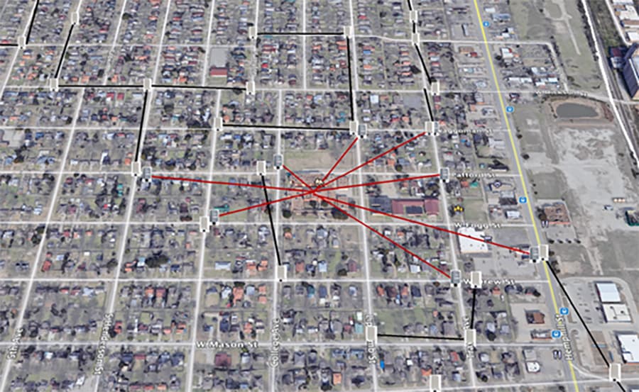
In the example shown in Final mesh radio network path, the black lines represent the FM1200 Volo Mesh Point RF path back to the FM3500 Endo. The red lines represent the backhaul RF path to the head end at the school. The FM1200 Volos depicted are representative of the RF path and may represent multiple radios to cover different directions on the street.
Installation Best Practices
When installing the radios in an outdoor environment, certain precautions must be taken. Waterproofing and grounding of all components must be performed according to the hardware installation guides or best practices. Each radio supports PoE with certain caveats and options. The FM3200 Base supports 802.3af and can be powered by a compatible PoE switch or PoE injector. It can also support 9-36VDC using the optional FM-POE-LOW-48 converter. The FM1200 Volo only supports 24VDC so it cannot be powered by a PoE switch directly. It can be powered by mains electrical power using the included 24V power injector (FM-POE-STD) or a third party active to passive PoE converter that converts standard 48V PoE (802.3af) to 24V (FM-POE-INL). The FM1200 Volo can also support 9-36VDC using the optional FM-POE-LOW converter. A surge suppressor is also recommended for the FM1200 Volo (FM-SURGE).
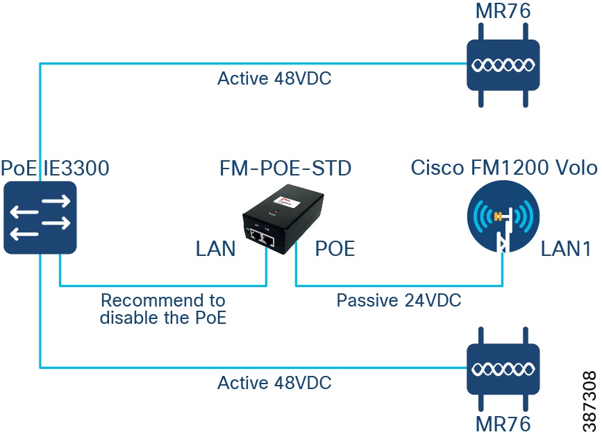
When a PoE enabled switch is required to connect multiple powered devices (PD), as depicted in Connect multiple devices to a PoE switch, a few caveats should be well understood. The Cisco FM1200 should be powered with a Cisco FM-POE-STD 24VDC passive PoE injector which is connected to an external main power source. The POE port of the injector should be connected to LAN1 port on Cisco FM1200, and the LAN port of the injector can only be connected to an 802.3 af/802.3 at standard compliant PoE switch like Cisco IE3300. Connecting to any non-standard compliant PoE switch could potentially cause damage to the power injector and the FM1200. To take additional precaution, it is also recommended to disable the PoE on the switch port that is connected to the injector. Meraki MR76 access points support 802.3af, can be powered normally via PoE from the same switch.
Figure 7 Connect multiple devices to a PoE switch
In the case where only one pair of Cisco FM1200 and Meraki MR76 are required at a particular location, they can be connected directly as represented in Connect Cisco FM1200 Volo and Meraki MR76 back-to-back. Again, the Cisco FM1200 should be powered with Cisco 24VDC passive PoE injector. The Meraki MR76 must be powered by a standard compliant 48VDC PoE injector such as MA-INJ-4-US. The powered device must be connected to the POE port of the injector with a straight ethernet cable. The LAN port on each PoE injector can be connected together either with a straight or crossover ethernet cable.
Figure 8 Connect Cisco FM1200 Volo and Meraki MR76 back-to-back

When mounting equipment on the poles or house, a number of factors must be considered. If a city is deploying the radio network on their own poles, there may not be restrictions. However, if some of the poles are owned by another organization, they may impose more restrictions. If they restrict the number of attachment points on the pole, special mounts and boxes may need to be fabricated to contain all the equipment. If there are power restrictions, the power budget may need to be more carefully scrutinized. In the case of a home installation, the mounting bracket and box aesthetics need to be considered as the homeowners may not want a large or unattractive box placed on their home.
RF best practices must also be followed during the installation. The radios must be installed at a height to allow for line of sight between the antennas. Additionally, the Fresnel zone, which is an area of radio waves between the transmit and receiver antennas, can ideally be 80% clear of obstacles or a minimum of 60%. Otherwise, the RF performance is significantly weakened.
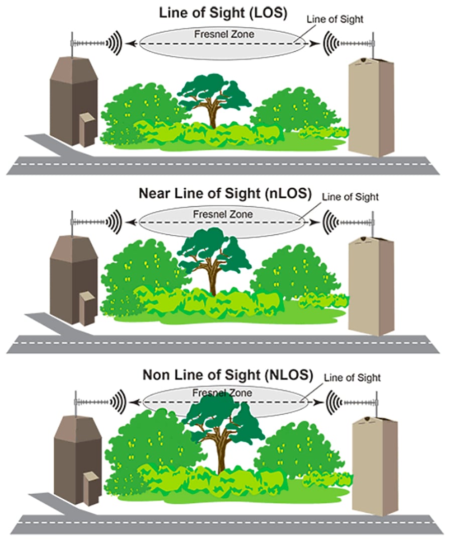
In cases where the line of sight cannot be achieved because of an obstacle, whether man made, like a building, or natural, like a hill, multiple point-to-point links can be used to send the signal around it. It is also important to note the season in which the site survey is being performed and the type of foliage in the area. In a new neighborhood with young trees, failing to take into account the tree growth could mean that in just a few years, the signal could be completely blocked. If the site survey is done in the fall or winter after the leaves have all fallen, the signal could be blocked come springtime if the radios are not mounted above the trees.
Figure 10 Street level line of sight
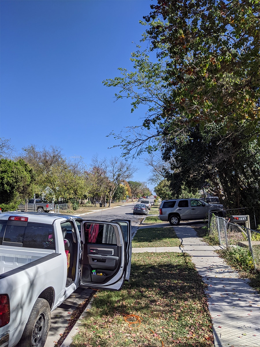
In Street level line of sight above, dense tree foliage will impede both the backhaul RF signal as well as the RF penetration into the houses. Placing the backhaul radios higher will improve the line of sight but there may still be issues with the Fresnel zone between them.
Figure 11 Pole level line of sight
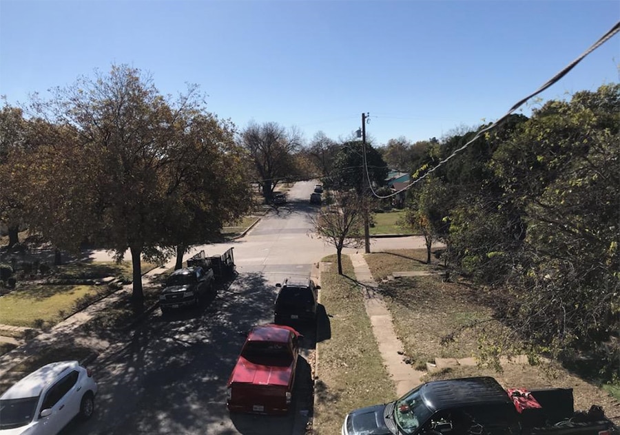
As seen in Pole level line of sight, some trees are above the pole height and coverage will be impaired if the radio density is low. This can be mitigated by trimming the trees or deploying more radios through the service area.
If multiple radios are installed on the same pole there must be a gap of at least 3 feet between them. If multiple radios are installed at the same height on a building, there must be at least 10 feet between them. The relative height difference between the Mesh End and Mesh Point radios must also be considered when determining the tilt of the antenna to provide the best line of sight path. If there is poor line of sight given the relative height differences, it may be necessary to position a point-to-point link from the radio at the head end to a tall vertical asset owned by the city or willing business. This point-to-point link could then serve as the backbone for a more direct link to the service area.
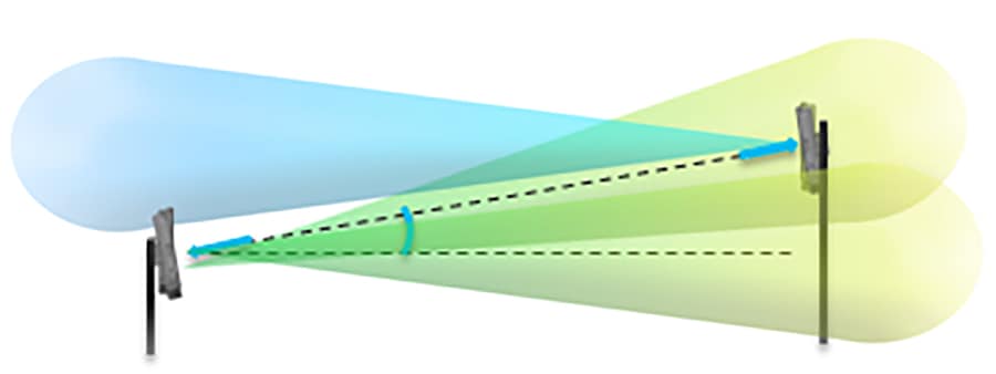
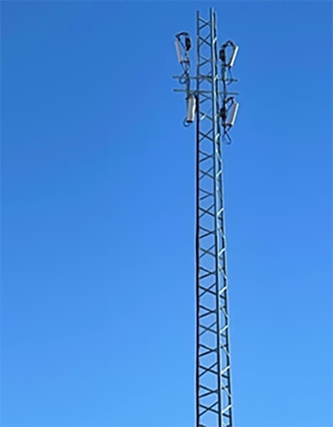
In cases where multiple radios are installed on a single tower to provide a wide coverage area, the FM3500 Endo may need to be used with an antenna providing a smaller beamwidth to not interfere with the other radios. Multi-radio tower is an example of four radios with separate antennas installed on a tall tower to cover a larger area.
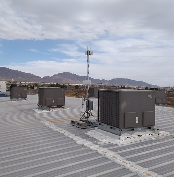
In Rooftop mounting, radios and antennas are attached to a pole on top of a building. However, there is not enough separation between the two lower radios and the proximity to the metal roof will likely cause many reflections to the RF signal. Also, by mounting the Meraki AP at the center of a big metal roof that is 20 feet above the ground, a large portion of the RF energy emitted by the omni antenna could be blocked by the surface area of the roof. The distance that the Wi-Fi signal can reach at ground level is significantly reduced. In this case, the Meraki AP should be moved to the edge of the roof and installed with a patch or sector antenna pointing in the direction of targeted coverage.
Radio Configuration
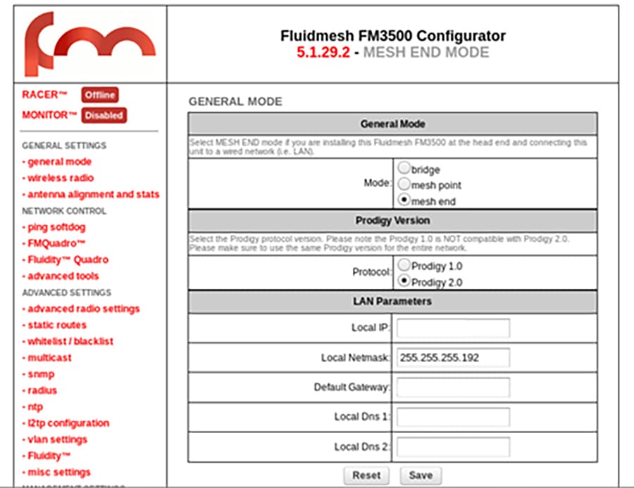
The FM3200 Base and FM1200 Volo can be configured using a few different methods. Cisco FM-Racer is a cloud-based tool that can be used in online or offline mode. It allows all the radio configuration to be done in a single pane and uploaded to the radios in real time or offline. It also supports all the configuration options. This is the preferred method for any size deployment. Another option is to use the built-in web configuration tool. Connecting to a radio in a web browser will give access to most of the configuration options. It is useful when configuring a small number of radios or when Internet access is not readily available. The final configuration method is using the command line interface (CLI) which gives access to all the configuration options but is less user friendly then the other options. If some advanced features need to be set on the radio but access to Cisco FM-Racer is unavailable, the CLI can be used.
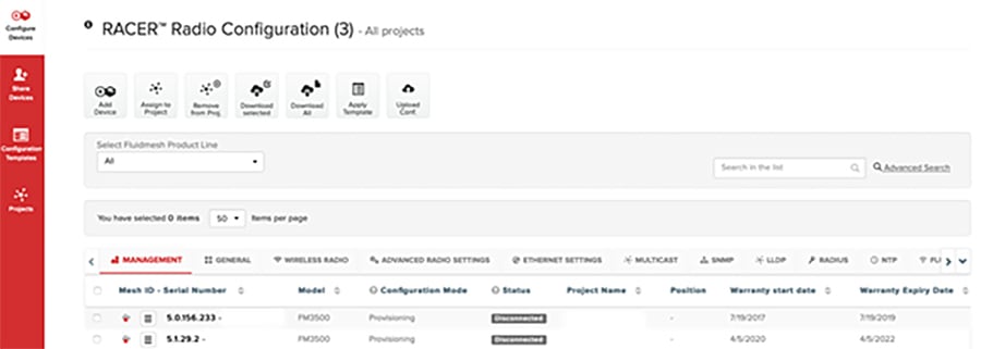
Figure 16 Cisco FM Configurator
Because Cisco FM-Racer can be used to configure all the radios in one interface, all radios can be pre-staged with their roles and configurations in a controlled environment before installation. Each radio has a unique Mesh ID number assigned to it. This Mesh ID distinguishes one radio from another in FM-Racer. After all the radios are configured, FM-Racer can update the radios in real time over the Internet or export the configuration as a single file that also includes any plugins and optionally the firmware assigned to this device. This file is then uploaded to the radio using the local web configuration UI and only the configuration for that Mesh ID is installed. Because there is only a single configuration file and each configuration is tied to the Mesh ID, the chance of installing the wrong configuration is eliminated.
A typical point-to-multipoint or point-to-point wireless network will have the same configuration components. The Mesh End and all the Mesh Points will have the same wireless passphrase. This passphrase ensures that only these radios can communicate with each other. All the radios in a cluster will have the same wireless frequency and channel width. For point-to-multipoint, there is a further configuration step enabling FluidMAX. When the Mesh End is configured as the FluidMAX Primary and all the Mesh Points are configured as FluidMAX Secondary, the Mesh End controls the frequency selections as well as the communication method to the Mesh Points. As the FluidMAX Primary, the Mesh End will use TDMA when communicating with the Mesh Points and all frequency selections only have to occur on the Mesh End. The Mesh Points will all receive the new changes without manual intervention.
Performance and Resiliency
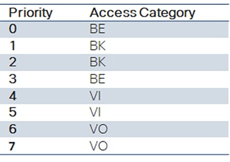
Choose software configuration options for the service level desired. Quality of Service (QoS) can be enabled on the radios which enables packet queueing. When enabled, the ingress mesh radio will inspect each packet and the DSCP field is examined. The three most significant bits of this field are used to prioritize the traffic into eight different priority levels similar to the IP Precedence Class Selector. This priority level is maintained until the packet reaches the egress mesh radio. When transmitting the data over the wireless interface, these eight priority levels are further mapped into four Access Categories representing Voice (VO), Video (VI), Best Effort (BE), and Background (BK). Refer to Packet priority and access category mapping. There are further QoS options that can change the default QoS map, enable shaping per QoS value, or force the radio to queue packets based on the 802.1p header instead of DSCP.
Table 9 Packet priority and access category mapping
In the Wireless Backhaul network, redundancy on the Mesh Ends is also an option. This feature is called MPLS Fast Failover or TITAN. When enabled on a pair of Mesh Ends, one takes on the primary role and the other, the secondary. The radios will then exchange keepalives and if the secondary does not hear the keepalive after a configured timeout, it will take over the role of primary and announce the change to the other radios and devices in the network.
Management and Troubleshooting
There are a number of tools that assist in the process of optimizing the radio network, visualizing the connections, and monitoring the radios after the installation. Each radio has a number of LED indicators on the outer casing that indicate the status of the radio operating mode as well as the signal strength. In the radio web configuration tool, there is an antenna signal strength link that shows the RSSI value to all the radios within RF range. In a point-to-multipoint deployment, the Mesh Points need a strong connection to the Mesh End.
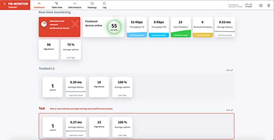
The Mesh End includes a reporting tool called FM-Quadro that provides a visualization of the connected Mesh Points and the link quality. Another separately-licensed product for monitoring the radios is called Cisco FM-Monitor. It can monitor every Wireless Backhaul radio in a network whereas the Mesh End can only monitor the radios to which it is connected. FM-Monitor can report average key performance indicators (KPIs) like latency, uptime, and jitter as well as the link error rate (LER) and packet error rate (PER) over the wireless connections. It can also display the real-time throughput on the radio network.
Meraki MR Installation, Configuration, and Design Considerations
MR Access Point Introduction
Meraki MR86 and MR76 are part of Meraki MR series WLAN access points that are designed for the highest performance for outdoor environment. The MR series is the world’s first enterprise-grade cloud-managed access point equipment that delivers the throughput and reliable coverage required by demanding business applications.
Every MR access point is equipped with the most advanced Wi-Fi 6 technologies including MU-MIMO, OFDMA, beam forming and channel bonding to deliver superior performance. In addition to the 5 GHz and 2.4 GHz 802.11ax radios, it has dedicated dual-band scanning and security radio that automatically monitors its surroundings and optimizes Wi-Fi performance of individual access points (APs) and maximizes system-wide performance. With Air Marshal, it is possible to set up a real-time wireless intrusion detection and prevention system (WIDS/WIPS) with user-defined threat remediation policies and intrusion alarms, enabling secure wireless environments without complex setup or systems integration.
The Cisco Meraki product portfolio is centrally managed from an intuitive web interface without controller hardware and management software to install and maintain, eliminating the cost and complexity of traditional physical wireless controllers. This cloud management architecture delivers zero-touch provisioning of the access point, network-wide application visibility and control, cloud-based RF optimization, seamless firmware updates, and more from a single pane of glass. This architecture can scale to any number of distributed multi-site networks. With open API services, Meraki cloud management platform can integrate with other technologies, build custom applications and automate the workflows.
The MR series comes with enterprise-grade security out of the box. It provides network segmentation based on wireless users, applications, and devices, secure the network from attacks and enforces the right policies for each class of users. The access points have built-in L3/L7 stateful firewall, provide traffic control via IP, Port, Protocol, application type and content categories and can route DNS requests through Cisco Umbrella. MR series provides 802.1x/RADIUS support, natively integrated with Active Directory, and customizable splash pages for better guest access control.
The MR76 and MR86 are both rugged, IP67 rated outdoor access points, delivering high-performance wireless connectivity to users in schools, neighborhoods, or in the community and city environment. The features of these two access points are highlighted in MR76 and MR86 feature comparison.
The key difference between these two access points are the MIMO schemes and number of spatial streams supported. The MR86 supports 4x4 MU-MIMO with 4 spatial streams, compared to 2x2 MU-MIMO with 2 spatial streams supported by the MR76. This enables the MR86 to achieve much higher data rates while communicating with a single client and a higher aggregate performance in an environment where simultaneous client connections exist. The MR86 is best suited for tough RF and high-density environments such as a large campus, multi-floor structure, convention center, sports arena, shopping mall, or city outdoor spaces where a high volume of users need Internet access. The MR76 could be deployed in a school neighborhood environment that has less density and throughput requirement. In the context of the digital divide solution, the MR76 is recommended to provide Wi-Fi to individual houses or areas where one AP covers limited number of clients; the MR86 can cover more dense areas such as apartment complexes, city parks, and public facilities where the population density is much higher.
Table 10 MR76 and MR86 feature comparison
MR Wireless Design Best Practice
Students continue their education through online learning, people work from home collaboratively, and social interaction is digital requiring a high performance and reliable Wi-Fi connection. Best practice for a good wireless design involves capacity planning and a site survey to achieve the goal. The following section presents some general best practices; for more details, refer to MR Wireless Best Practice Design.
Capacity Planning
Understanding the user requirements is the first step to a successful design. Requirements can be the number of users, client devices, device capabilities, application bandwidth, and latency needs. A wireless design engineer can have following details before moving onto the next step in design phase:
■![]() Type of applications expected on the network
Type of applications expected on the network
■![]() Supported technologies (802.11 a/b/g/n/ac/ax)
Supported technologies (802.11 a/b/g/n/ac/ax)
■![]() Device capabilities (number of spatial streams, technologies, band, type of device, etc.)
Device capabilities (number of spatial streams, technologies, band, type of device, etc.)
■![]() Expected number of simultaneous devices in each area
Expected number of simultaneous devices in each area
■![]() Power constraints (use PoE+ capable infrastructure to support high performance APs)
Power constraints (use PoE+ capable infrastructure to support high performance APs)
The details above help in capacity planning such as:
Estimate Aggregated Application Throughput
Typically, a primary application drives per-user and per-connection bandwidth requirements. Published primary application throughput is shown below. Testing the target application for actual bandwidth requirements is recommended, due to disparity of the throughput requirements caused by different in device operating systems or browser efficiencies.
Table 11 Typical application throughput*
After the primary application throughput is known, the aggregate bandwidth required in a specific area can be determined. Two examples are presented below:
Example 1: Single household in a school district
There are four users at a home, two students consume 3Mbps at each connection when doing remote learning weekdays using Webex with HD Video, or watching live video streaming after school. Two parents living in the same house browse the Internet, check emails and social medias, or do basic video conferencing that consumes 2Mbps per connection. The estimated aggregated application throughput for this household can be calculated using following formula:
(Application throughput) x (number of concurrent users) = aggregate application throughput
(3.0Mbps x 2 users)+(2.0Mbps x 2 users) = 10Mbps per household
Example 2: High density environment
At a campus, apartment complex, sports venue, community gathering location, etc. Support for HD video streaming requires 3Mbps of throughput, estimated 600 users total watching HD video streaming. The aggregated application throughput equals: 3Mbps x 600 users = 1800Mbps. This is an example only, the solution for this scenario is not addressed in this reference guide.
Estimate Device Throughput
Meraki APs support the latest technologies and can support maximum data rates defined by the standards. The average device throughput available is often impacted by factors such as client capabilities, concurrent clients per AP, supported technologies, channel usage, application data overhead, etc.
Wi-Fi client capabilities have significant impact on throughput. A client that will only support legacy rates has a much lower throughput compared to a client supporting newer technologies. A client that only supports 2.4GHz might have lower throughput compared to a dual band client due to more noise and interference is expected on 2.4GHz compared to 5GHz. In certain cases, having separate SSID for each band is also recommended to handle client distribution and compatibility issues. In order to reduce the size and increase the battery life, most of the device manufacturers design the devices with one or two Wi-Fi antennas inside, which deviates from 802.11ac standard implementation.
This design results in lower speeds at client devices by limiting them to a lower stream than supported by the standard. One example, device support 1 stream only delivers 87Mbps at 20MHz channel versus device that supports 3 streams can deliver 289Mbps at same channel width. Meraki dashboard client details page is an easy way to determine client device capabilities.

When deciding the device throughput, packet overhead must also be taken into consideration. A conservative estimate of a device actual throughput is about half of the data rate advertized by the manufacturer. It is also good practice to reduce the throughput by 30% in the calculation, considering multiple factors affecting performance.
Estimate number of APs
After the aggregate application throughput and device throughput are determined, you can calculate the required number of APs based on throughput in a specific area using following formula. Round the result to the nearest whole number.
■![]() Number of Access Points based on throughput = (Aggregate Application throughput) / (Device throughput)
Number of Access Points based on throughput = (Aggregate Application throughput) / (Device throughput)
In addition to calculating the number of APs based on throughput, you also need to consider the number of APs based on the client count. To maintain quality of service, approximately 25 clients per radio or 50 clients per AP are recommended in a high-density deployment.
In the case where the usable bandwidth is limited per user, aggregated application throughput is not the key decision factor to calculate number of access points required. Instead, coverage and number of users to be supported become important factors to determine how many APs are required.
Estimate throughput license for Cisco Ultra-Reliable Wireless Backhaul radios
The aggregated throughput of a particular area provides guidance to calculate throughput requirements for Cisco wireless backhaul radio. To continue with the previous example, every household has a10Mbps throughput requirement. Each house is served by one then MR76 access point which is connected to one Cisco FM1200 Volo mesh point. Configure the mesh point radio with a 10Mbps Ethernet throughput license. Assuming there are 15 Cisco FM1200 Volo connected to the same Cisco FM3200 Base mesh end radio in a point-to-multipoint wireless topology, the Cisco FM3200 Base radio requires a 150Mbps throughput license. The same logic can be followed to calculate every Cisco wireless backhaul radio Ethernet throughput license in this network.
Site Survey and Design
It is critical to perform an active site survey for successful deployment of wireless networks, and it helps to evaluate the RF propagation in the actual physical environment. RF propagation is an important factor that affects the overall user experience in this solution. Even though it is best effort to provide Wi-Fi access inside the house, RF propagation analysis is key to characterize different data rates at different locations inside the house.
RF propagation at each house in an area is different depending on the height of the AP mounted relative to the RF penetration point into the house, the distance and line of sight condition between each house and AP, building material of the house, etc. The active site survey must also consider live performance testing, to measure the data throughput coverage in addition to the range.
It is also good practice to have a spectrum analysis as part of the site survey using a professional grade toolkit such as Ekahau Site Survey in order to locate any potential sources of RF interferences, so that necessary steps can be taken to remediate them before turning on the service. Other best practices are to survey for adequate coverage on 5GHz channel in addition to 2.4GHz to make sure there are no coverage holes, to guarantee a minimum of 25 dB Signal-to-Noise (SNR) throughout the coverage area, and to avoid excessive co-channel interference between all the access points in the high density environment. Refer to the Meraki RF site survey guide Conducting Site Surveys with MR Access Points for more details.
MR Installation Guide
The best practice for installing an MR access point is to follow the MR76 installation guide and MR86 installation guide. A few important aspects are highlighted here: pre-install preparation, AP mounting options, antenna options and mounting instructions, and power requirements.
The following are steps required before going on-site to perform an installation:
■![]() Configure the network using the Meraki dashboard
Configure the network using the Meraki dashboard
■![]() Configure the firewall settings to allow outgoing connections on specific ports to specific IP addresses. The most common list can be found in “ Upstream firewall rules for cloud connectivity”ere
Configure the firewall settings to allow outgoing connections on specific ports to specific IP addresses. The most common list can be found in “ Upstream firewall rules for cloud connectivity”ere
■![]() Assign IP address to MR APs: dynamic (preferred), static, or static IP via DHCP reservations
Assign IP address to MR APs: dynamic (preferred), static, or static IP via DHCP reservations
For best performance, a good mounting location is important. Performing an active site survey can help you to achieve the goal. In addition, keep these things in mind:
■![]() The device must have line of sight to most coverage areas
The device must have line of sight to most coverage areas
■![]() Power over Ethernet (PoE) supports a maximum cable length of 300 ft (100m)
Power over Ethernet (PoE) supports a maximum cable length of 300 ft (100m)
■![]() Make sure there is clearance around APs for chosen antennas installation
Make sure there is clearance around APs for chosen antennas installation
Digital divide solutions usually pole mount components to utility poles or street light poles. Sometimes the equipment can be mounted at the house by surface mount or wall mount. For pole mount, use the mounting straps included for a pole less than 3.9” in diameter. Secure the mounting plate in a horizontal or vertical orientation. When mounting Meraki APs and other radios on the same pole, a maintain a 1-foot clear space between each radio and antenna.
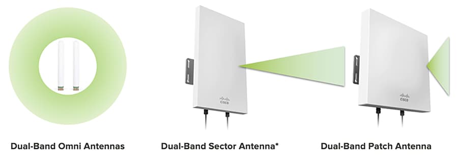
Meraki offers variety of antenna for MR access points including omni-directional, patch, and sector antenna. Check the installation guide for the right antenna for your application. Omni antenna (MA-ANT-20) is recommended in this guide for broad range of applications due to its 360-degree signal coverage patterns.
When applications require client coverage over focused areas, Meraki dual-band patch antenna (MA-ANT-25) or dual-band sector antenna (MA-ANT-27) is recommended. Both antennas can extend the range of a Cisco Meraki outdoor access point by focusing the wireless signal in a specific direction. Typically, a sector antenna is more focused than a patch antenna and can transmit and hear signals farther away. Check Meraki antenna specifications and Meraki antenna coverage comparison for the comparison between different antennas. MR76 and MR86 has total 4 N-type RF connectors for the antenna, two are located at the top of the AP and two are located at the bottom of it. Two antenna ports at the top of MR76 are dedicated to 2.4GHz, and two at the bottom are dedicated to 5GHz. The four antenna ports of MR86 are connected to both 2.4GHz and 5GHz client serving radios. In addition, make sure the right antenna in Meraki dashboard is selected when adding the AP to a network.
Table 12 Meraki antenna specifications
|
|
|
|
|
|
|
|||
Figure 19 Meraki antenna coverage comparison
Both Meraki APs can be powered via the PoE injector which is connected to an AC power source or PoE supported switch like Cisco Catalyst Industrial Ethernet switches IE3300. MR76 requires only 802.3af power to operate in normal mode, and MR86 requires 802.3at power to operate.
MR Configuration Best Practice
Access Control Configuration
The Digital Divide solution provides Wi-Fi access to the underserved community so that students can continue their education remotely. Additionally, this solution delivers Wi-Fi access to other people in the same household, neighborhood and community. Two different SSIDs with different access control policies can be considered when granting network access to the users. Students can associate to a dedicated SSID, for instance “ABC School District Wi-Fi”, the rest of people can associate to an open public Wi-Fi called “ABC City Free Wi-Fi". Different policies can be applied as illustrated in the following sections.
Student Wi-Fi Access Control
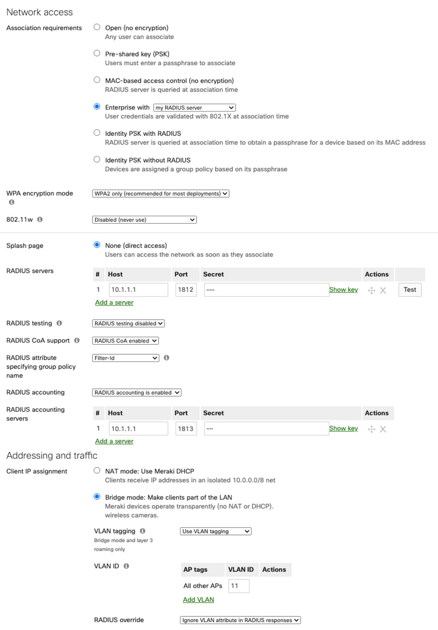
For the students Wi-Fi access, it is recommended to leverage external authentication servers to support WPA2-Enterprise authentication such as Remote Authentication Dial-In User Service (RADIUS). It is the best practice to keep RADIUS server and APs within the same Layer 2 domain to avoid firewall, routing, or authentication delay. Active Directory (AP) can be used as user database for RADIUS if it has been deployed at school. The following are configuration steps to enable RADIUS authentication on a Meraki access point assuming the RADIUS server has been properly configured. For detailed configuration please refer to the RADIUS configuration guide.
1.![]() Name of the SSID “ABC School District Wi-Fi"
Name of the SSID “ABC School District Wi-Fi"
2.![]() Association requirements: Enterprise with “my RADIUS server”
Association requirements: Enterprise with “my RADIUS server”
3.![]() WPA encryption mode: WPA2 only
WPA encryption mode: WPA2 only
5.![]() RADIUS servers: add a server with IP address, port number (1812), and shared secret
RADIUS servers: add a server with IP address, port number (1812), and shared secret
6.![]() RADIUS CoA support: enabled
RADIUS CoA support: enabled
7.![]() RADIUS attribute specifying group policy name: Filter-Id
RADIUS attribute specifying group policy name: Filter-Id
9.![]() RADIUS accounting servers: add a server with IP address, port number (1813), and a shared secret
RADIUS accounting servers: add a server with IP address, port number (1813), and a shared secret
10.![]() Client IP assignment: Bridge Mode - allowing wireless clients to obtain the IP addresses from an upstream DHCP server normally located inside the school network.
Client IP assignment: Bridge Mode - allowing wireless clients to obtain the IP addresses from an upstream DHCP server normally located inside the school network.
11.![]() Content Filtering: This function is disabled under Bridge Mode. Refer to the later section on how to apply content filtering using Cisco Umbrella.
Content Filtering: This function is disabled under Bridge Mode. Refer to the later section on how to apply content filtering using Cisco Umbrella.
12.![]() Enable VLAN tagging: Configure SSID-wide with single VLAN tag. For detailed configuration of VLAN, see “ VLAN tagging configuration on MR Access Points ”
Enable VLAN tagging: Configure SSID-wide with single VLAN tag. For detailed configuration of VLAN, see “ VLAN tagging configuration on MR Access Points ”
Figure 20 MR RADIUS configuration example
General Public Free Wi-Fi Access Control
For the general public free Wi-Fi access, the following configurations best practices apply:
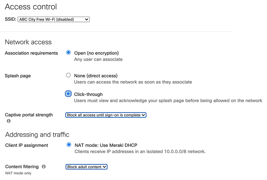
■![]() Name of the SSID “ABC City Free Wi-Fi"
Name of the SSID “ABC City Free Wi-Fi"
■![]() Association requirements: Open
Association requirements: Open
■![]() Splash page: Click-through. User must view and acknowledge the splash page before being allowed on the network
Splash page: Click-through. User must view and acknowledge the splash page before being allowed on the network
■![]() Client IP assignment: NAT mode: Use Meraki DHCP. In NAT mode, client will get the IP address from DHCP runs on the AP itself. There is no connection between wireless clients. Layer 3 and Layer 7 firewall can be applied to prevent certain access which will be discussed in firewall and traffic shaping section below
Client IP assignment: NAT mode: Use Meraki DHCP. In NAT mode, client will get the IP address from DHCP runs on the AP itself. There is no connection between wireless clients. Layer 3 and Layer 7 firewall can be applied to prevent certain access which will be discussed in firewall and traffic shaping section below
■![]() Content Filtering: Block adult content
Content Filtering: Block adult content
■![]() Captive portal strength: Block all access until sign-on is complete
Captive portal strength: Block all access until sign-on is complete
Figure 21 Sample configuration for open free Wi-Fi
Firewall, Traffic Shaping, and QoS
MR series AP supports custom firewall rules that allows more granular access control. The firewall rules are be applied for a given SSID or as part of group policy. Every packet sent through the AP will be evaluated against the set of firewall rules from top to bottom. The first rule that matches is applied, and subsequent rules are not evaluated. If no rules match, the default rule (allow all traffic) is applied. MR APs support both Layer 3 and Layer 7 firewall rules.
Layer 3 Firewall
Layer 3 firewall rules on the MR are stateless and can be based on destination address and port. It is a good practice to block traffic from public free Wi-Fi to upstream network access The following example illustrates set of custom firewall rules that is enforced at Layer 3. The rule block wireless client to access any upstream private LAN networks that are defined in RFC1918.
Figure 22 MR Layer 3 Firewall Configuration Example

Layer 7 Firewall
Cisco Meraki access point supports Network-Based Application Recognition (NBAR) engine that allows better application visibility and more granular Layer 7 and traffic shaping rules. It supports more than 1400 applications and sub-classifications, with less than 1% unknown and less than 1% unclassified encrypted traffic. Refer to the NBAR integration guide for full capabilities. It can completely block certain applications without having to specify specific IP addresses or port ranges. This can be useful when applications use multiple or changing IP addresses or port ranges. The Layer 7 firewall rules can block applications by category (for example 'Gaming' and Peer-to-Peer) or for a specific type of application within a category (for example only Windows file sharing within the 'File sharing' category). MR Layer 7 Firewall configuration example below depicts a set of Layer 7 firewall rules including applications blocked by entire categories and specific applications blocked within a category.
Figure 23 MR Layer 7 Firewall configuration example

Denying wireless clients access to the LAN by applying the layer 3 firewall rules, and block application categories such as peer-to-peer and gaming is recommended because the focus of this solution is to support remote learning and online education.
Traffic Shaping
To ensure that users do not consume more bandwidth than they are allowed, applying traffic shaping rules to enforce both upload and download speed is recommended. The Meraki dashboard supports separate upload and download limits, and the limits can be applied per SSID or per user.
To configure per SSID bandwidth shaping, go to the Firewall and Traffic Shaping page under the Configuration tab. Based on the bandwidth calculation discussed in the prior capacity planning section, 10Mbps bandwidth is required per household, two students can allocate 3Mbps bandwidth each, and two parents can have 2Mbps. Assuming each person uses one device at a time, you can configure the traffic shaping per-client as illustrated in the following example. For any situation that does not match this assumption, such as the number of devices exceeds 4, or the total bandwidth per household is more than 10Mbps, different capacity planning and traffic shaping rules can be considered.
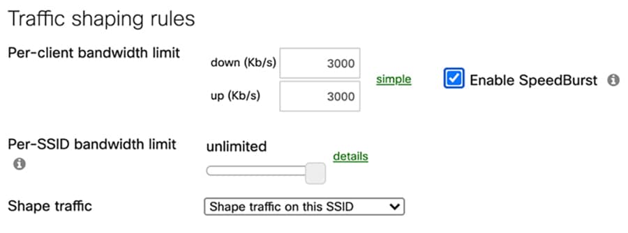
For the student Wi-Fi SSID, the Per-client bandwidth limit is set to 3Mbps in each direction, with “Enable Speedburst” option checked. Speedburst can allow users to temporarily exceed four times the bandwidth limit for up to 5 seconds while still keeping them under the bandwidth limit over time.
Figure 24 Traffic shaping rules configuration for students Wi-Fi SSID
For the general public Wi-Fi SSID used by parents, the per-client bandwidth limit is set to 2Mpbs.
Figure 25 Traffic shaping rules configuration for general public free Wi-Fi SSID

Meraki AP integrates with Network-Based Application Recognition (NBAR), that supports more than 1400 applications and sub-classifications. This allows more granular Layer 7 firewall and traffic shaping rules to be configured. For instance, you can create traffic shaping rules to rate limit just the BitTorrent application in peer-to-peer category or all gaming applications in Gaming category down to very minimum bandwidth so that sufficient bandwidth is allocated to applications that students are using for education.
The following is an example of traffic shaping rule created to limit the BitTorrent application to 50Kbps.
Figure 26 BitTorrent traffic shaping rule

Access Point QoS
Quality of Service is a network control mechanism that can ensure better service for a selected traffic type. QoS provides several priorities and guarantees the level of performance of a traffic flow. MR access points feature enterprise-class QoS and uses a standard in wireless network called Wireless Multi Media (WMM). WMM delivers four different traffic classes: Voice, Video, Best Effort and Background.
MR access points maps Ethernet DiffServ values to WMM access categories in downstream marking. Meraki AP RFC4594 to WMM marking mapping highlights some of the most relevant traffic and their specific markings. Meraki access points honor all upstream QoS sent by the client or can mark upstream traffic by defining traffic shaping rules with QoS settings. Meraki MR AP implements Enhanced Distributed Channel Access (EDCA) to handle traffic queueing. Access points maintain a queue for each WMM access category on a per-client basis. When transmitting a frame, EDCA defines backoff timers for each class which prioritizes traffic based on airtime.
Table 13 Meraki AP RFC4594 to WMM marking mapping
|
|
|
|
|
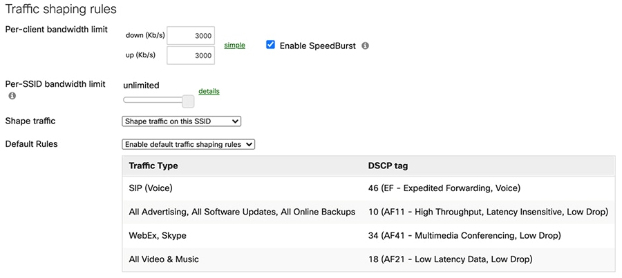
In the previous section, the traffic shaping rule is configured to provide bandwidth limit based on per-client so that no single user can consume more bandwidth than allowed. In the case of congestion which may be caused by someone watching live video streaming or performing large file transfer or online backup, a certain level of performance still needs to be maintained for applications like Webex so that student remote learning experience does not decline. Default traffic shaping rules QoS settings represents the default traffic shaping rules with QoS which can be enabled and applied to the specific SSID. In the default shaping rules, Webex application that has DSCP AF41, will be put into the Video access category under WMM. All live video streaming applications that have DSCP AF21 will put in the Best Effort category. All online backup applications that have AF11 will be put in the Background access category.
It is not expected to see congestion on the Meraki side as per client bandwidth is limited by each AP. The oversubscription would happen at backhaul network where traffic is aggregated. In order to maintain end to end QoS, upstream devices like Cisco wireless backhaul radios and Cisco Industrial Ethernet (IE) switches should also have proper QoS configured and maintain consistent QoS settings as Meraki AP. To maintain end-to-end QoS, upstream devices like Cisco wireless backhaul radios and Cisco Industrial Ethernet (IE) switches must also have the proper QoS configured. Refer to those sections for details.
Figure 27 Default traffic shaping rules QoS settings
Traffic shaping and firewall can also be configured via group policy. Please follow the group policy configuration guide to understand how to create and apply group policies on Meraki access points.
Radio Settings
Based on the RF site survey and capacity planning results, reviewing the default radio setting in the Meraki dashboard and making necessary adjustments based on the requirements is recommended. Here are some best practices to be considered:
■![]() Enable dual band operation per AP to support legacy clients for more capacity and less interference.
Enable dual band operation per AP to support legacy clients for more capacity and less interference.
■![]() Select the “Band Steering” option to detect clients capable of 5GHz operation and direct the traffic from them to that frequency which leaves the more crowded 2.4 GHz band available for legacy clients.
Select the “Band Steering” option to detect clients capable of 5GHz operation and direct the traffic from them to that frequency which leaves the more crowded 2.4 GHz band available for legacy clients.
■![]() Set Channel width to AUTO and Auto channel assignment work in most cases for this solution but do not select to verify if there is any channel overlapping and co-channel interference. Manually adjust the channel width and channel assignments if necessary.
Set Channel width to AUTO and Auto channel assignment work in most cases for this solution but do not select to verify if there is any channel overlapping and co-channel interference. Manually adjust the channel width and channel assignments if necessary.
■![]() Transmitting power affects the wireless coverage area and the maximum achievable signal-to-noise ratio. Two settings ensure proper configuration for the wireless network to operate at its highest capacity:
Transmitting power affects the wireless coverage area and the maximum achievable signal-to-noise ratio. Two settings ensure proper configuration for the wireless network to operate at its highest capacity:
–![]() Auto transmit power is the default and recommended setting. It leverages RF data collected by an AP to decide which radio transmit power level would be best for client performance.
Auto transmit power is the default and recommended setting. It leverages RF data collected by an AP to decide which radio transmit power level would be best for client performance.
–![]() The Manual setting allows the user to adjust transmit power per band. Even though the radio can be set to transmit at maximum power, the AP may prevent it from broadcasting because of regulatory domain, channel selection, and bit rate.
The Manual setting allows the user to adjust transmit power per band. Even though the radio can be set to transmit at maximum power, the AP may prevent it from broadcasting because of regulatory domain, channel selection, and bit rate.
■![]() Select a lower Minimum bit rate value to support legacy devices and extend the reach of the AP.
Select a lower Minimum bit rate value to support legacy devices and extend the reach of the AP.
■![]() When an external antenna is used, the dashboard needs to have the proper antenna option selected (Wireless->Monitor->Access Points->Access Point Details) to match the antenna installed and enforce regulatory restrictions such as Equivalent Isotropically Radiated Power (EIRP).
When an external antenna is used, the dashboard needs to have the proper antenna option selected (Wireless->Monitor->Access Points->Access Point Details) to match the antenna installed and enforce regulatory restrictions such as Equivalent Isotropically Radiated Power (EIRP).
IE Installation, Configuration and Design Considerations
Cisco Catalyst Industrial Ethernet (IE) Switches Introduction
Cisco Catalyst Industrial Ethernet IE3300 switches deliver Gigabit Ethernet connectivity in a compact form factor that is purpose-built for wide range of industrial applications where harden products are required for harsh environments. The modular design of the Cisco Catalyst IE3300 Rugged Series offers the flexibility to expand to up to 26 ports of Gigabit Ethernet or up to 24 ports of Gigabit Ethernet and 2 ports of 10 Gigabit (10G) Ethernet with a range of expansion module options.
The IE3300 Gigabit series supports power budget up to 360W, and 10G series supports power budget up to 480W shared across up to 24 ports. It supports IEEE 802.3af and 802.3at on all series, 802.3bt type 3 & 4 on 10G series, is ideal for connecting high power PoE end devices such as high power 802.11ac Wave 2, 802.11ax wireless access points, IP cameras, phones, and more.
These switches run Cisco IOS XE, a next-generation operating system with built-in security and trust, featuring secure boot, image signing, and the Cisco® Trust anchor module. Cisco IOS XE also provides API-driven configuration with open APIs and data models. In addition to the richness of Layer 2 software features supported on this platform, IE3300 supports full Layer 3 routing functions. In combination with wide range of expansion module options and upscaled PoE support, it is the perfect platform for not only connecting multiple devices like Meraki APs and Cisco wireless backhaul radios in this solution, but also enabling schools and cities to expand their future network capabilities by connecting other devices like IP cameras, traffic signal controllers, and C-V2X radios (Cellular based Vehicle to everything). at much larger scale to support city, roadways and intersection use cases.
Figure 28 IE 3300 with 10G uplinks and IE 3300 with 1GE uplinks

IE Installation Best Practice
The IE3300 base module has 8 GE copper downlink ports and 2 GE or 2 10G SFP uplink ports. It has variety of IEM-3300 expansion modules that provide additional ports and PoE support. IE3300 series switches support multiple power supply options, provides power up to 480W. When ordering the power supply, the entire power budget including switch and PoE ports must be considered. For details of supported models, expansion module, SFP matrix, and power supply options, refer to the IE3300 datasheet.
When connecting to Cisco wireless backhaul radios and Meraki APs, 10/100/1000 Base-T downlink port of the IE3300 Base or expansion module is used. In all cases, the attached devices must be within 328 feet (100m) and PoE requirements must be considered. Cisco FM1200 Volo only supports 24VDC, it cannot be directly connected to a PoE switch. Refer to the previous Cisco wireless backhaul section for guidance on how to connect a FM1200 Volo radio to a PoE switch. The switch has a dual-feed DC power supply; two connectors provide primary and secondary DC power (DC-A and DC-B). Each power connector has screw terminals for connecting the DC power. All connectors are attached to the switch front panel with the provided captive screws. The switch can operate with a single power source or with dual power sources. When both power sources are operational, the switch draws power from the DC source with the higher voltage. If one of the two power sources fail, the other continues to power the switch.
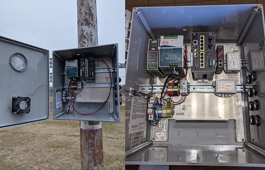
IE3300 series switch is IP30 rated, not certified for outdoor operation without a proper enclosure. The photographs in IE enclosure and mounting example represent examples of enclosures. In most cases, the IE switch is DIN rail mounted in the enclosure. The latch for the DIN rail is located at the back panel of the switch. The design of the enclosure has to take into consideration the space and ventilation required to make sure IE switch operates within its specifications. A temperature sensor can be installed to turn on a fan when the temperature inside the enclosure exceeds the threshold. In order to power the Cisco FM1200 Volo, an additional stepdown transformer has to be installed to provide 24VDC input.
Figure 29 IE enclosure and mounting example
IE Configuration Best Practice
A Cisco Catalyst IE3300 is positioned to provide local connectivity when the number of devices connected is more than two. For instance, three devices mounted on a utility pole, can include two Meraki access points delivering Wi-Fi to multiple homes and one Cisco FM1200 Volo radio acting as mesh point in point-to-multipoint backhaul connection. These three devices are logically connected together via one IE3300 switch. Initially, the IE switch is not connected to any city-wide fiber network, nor interconnected in a ring topology to provide fully resilient and redundant network infrastructure. The Cisco wireless backhaul connection is normally terminated at a headend switch located at school or at an Internet PoP from the ISP.
VLAN Configuration Best Practice
One common management VLAN is recommended to manage all the devices in the network. Different data VLANs can be configured to segment the network into a manageable Layer 2 broadcast domain. The following two examples present how the VLAN can be configured with IE3300, Cisco FM1200 Volo mesh point, Cisco FM3500 Endo mesh end, and a headend switch such as Catalyst 9300 in a point-to-point backhaul connection. The same principle can be applied to a point-to-multipoint connection. During the configuration designing phase, VLAN planning has to be performed carefully to make sure the expected result is achieved. In addition, ensure that the VLAN plug-in is enabled on Cisco wireless backhaul radios and only relevant VLANs are allowed in switch trunk configuration. For security reasons, VLAN 1 is not configured as the native VLAN.
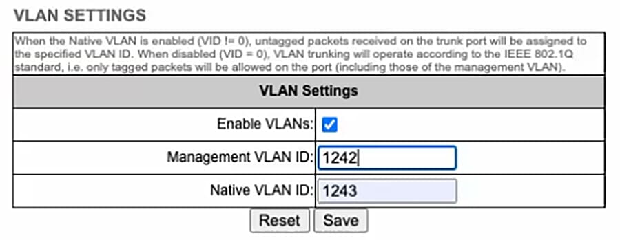
VLAN configuration for MR connects to IE3300 presents a configuration example where a MR76 connects to a IE3300, data traffic is on VLAN 11, Cisco wireless backhaul radio management traffic is on VLAN1242, and native VLAN is configured with VLAN1243. In this case, the Gigabit Ethernet port connecting to MR access point can be configured as the trunk port with VLAN 11 allowed, and the port connecting to FM1200 Volo can be configured as a trunk port with the native VLAN 1243. The tagged traffic generated from MR passes IE3300 with tag 11. Because the Native VLAN ID (NVID) on both wireless backhaul radios are configured as 1243 which is different from the VLAN 11 tag, the traffic passes through Cisco wireless backhaul with tag 11. The port on the CAT9300 that is connected to the FM3500 Endo mesh end is configured as a trunk port with native VLAN 1243.
Figure 30 VLAN configuration for MR connects to IE3300

VLAN configuration for MR connects to Cisco FM 1200 Volo presents another configuration example where a MR76 or MR86 connects to a Cisco FM1200 Volo directly without an IE switch, data traffic is on VLAN 11, Cisco FM radio management traffic is on VLAN1242. To ensure the data traffic passing the network reaches the headend switch on VLAN 11, the FM1200 Volo mesh point radio is configured with native VLAN 11 and management VLAN 1242. The Cisco FM3500 Endo mesh end radio can be configured with management VLAN 1242, and native VLAN 1243 (or any available VLAN other than 11). The port on the CAT9300 that is connected to the Cisco FM3500 Endo mesh end radio is configured as a trunk port with native VLAN 1243. In this configuration, the untagged traffic from MR76 will exit the Cisco FM1200 with tag 11, and pass through the network with tag 11 retained.
Figure 31 VLAN configuration for MR connects to Cisco FM 1200 Volo

Figure 32 Cisco Wireless Backhaul Radio VLAN configuration example
IE QoS Configuration Best Practice
The Cisco IE3300 switch supports Quality of Service (QoS) which allows a certain type of traffic to be treated differently at the expense of others, so the performance of high priority traffic such as Webex can be assured. Classification and marking are the first steps to implement QoS. Classification differentiates traffic type by examining the packet header. A packet can be classified based on the DSCP, the COS, and the IP precedence value in the header. It can also be classified with VLAN ID and Access control list (ACL).
Classification and marking is recommended at the entry point of the network. After the traffic is classified, certain QoS features can be applied in the policy map depending on the ingress or egress direction of the traffic. In the case of input policy applied to ingress traffic, the IE3300 can be configured either to trust the marking from the client device or set it to a different value based on business requirements; for output policy that is applied to egress traffic, you can assign a percentage of bandwidth, shape transmission to certain rate, or set a queue-limit for specific traffic type. IE3300 supports multiple queueing models such as class-based weighted fair queuing (CBWFQ), and priority queuing. CBWFQ is recommended in this solution to allocate a percentage of bandwidth for a specific application.
For example, the Webex application has been configured with AF41 in the Meraki AP, the IE3300 can be configured to match this DSCP value and then assign 50% of the bandwidth to guarantee the service level of this application. For detailed QoS design, refer to the QoS section in Connected Communities Infrastructure (CCI) Design Guide and the IE3300 QoS Configuration Guide.
IE Provisioning and Management Best Practice
The Cisco Catalyst IE3300 Rugged Series can be managed with powerful management tools such as Cisco DNA Center (DNAC) and Cisco Industrial Network Director (IND), or it can be easily set up with a completely redesigned user-friendly modern GUI tool called WebUI. The switch supports a comprehensive set of Management Information Base (MIB) extensions and four Remote Monitoring (RMON) groups. Switches can be managed from a SNMP-compatible management station. You can also fully configure and monitor the switch via Cisco IOS CLI, by connecting your management station directly to the switch management port, or a console port, or by using Telnet from a remote management station.
Depending on a customer’s existing management platform infrastructure and objectives, an appropriate and cost-effective management solution can be determined. If customer wants to have a quick start to manage their network, WebUI can be leveraged to provision and configure the IE series switches with simple configurations like VLAN, IP and basic QoS. If the customer already has large scale Cisco network infrastructure in place being managed or planning to be managed by DNAC, these IE switches can be easily provisioned, deployed, and managed at scale with its policy-driven automation and assurance. In this case, the DNA Center Day N template feature is recommended to configure QoS on these switches.
Security Design Best Practice
Segmentation
Network Segmentation is one of the best practices in dealing with cyber security by dividing a large network into different small parts and control the traffic flow between different parts of the network. You could limit all the traffic in one segment of the network from reaching another, or you can limit the flow by protocol, port, source/destination IP address, and application types. Some of the key benefits of network segmentation include improved operational performance by reducing network congestion, limiting cyberattack damage by limiting how far an attack can spread, and protecting vulnerable devices by stopping traffic from reaching devices that cannot protect themselves.
There are many ways to implement the network segmentation including traditional technologies like Access Control List (ACL), Virtual Local Area Network (VLAN), and firewall configurations on networking equipment. Unfortunately, these approaches are costly and difficult. Today, with Cisco Intent-based networking and software-defined access (SDA) technology, segmentation can be implemented by grouping and tagging network traffic with a secure group tag (SGT). Cisco Identify Service Engine (ISE) and DNA Center (DNAC) can then automatically apply relevant secure group ACL (SGACL) policies based on traffic classification down to the device node to segment to secure the network without the complexity of traditional approaches.
The Digital Divide Solution provides a secure Wi-Fi access to students and the existing school IT security policy for students can be applied to this Wi-Fi extension at home. As discussed in the previous chapter, this solution relies on school current Active Directory identity database to provide user authentication and access control. This prevents other non-student users from getting on the student Wi-Fi and posing security threats to school network. The same segmentation and firewall rules applied to students at school can be extended to those at home. For instance, student access to the school financial department can be completely blocked, and inappropriate websites can be filtered and denied access.
In addition to providing Wi-Fi to students, this solution can also enable communities and cities to provide free Wi-Fi to the general public in underserved communities. Without requiring user authentication for access, this Wi-Fi network can be its own dedicated virtual network, fully segmented and firewall protected from the rest of the city network. This prevents unauthorized access and malicious attack to any city operated network. For detailed design considerations, refer to the “Security Architecture and Design Considerations” chapter in the Connected Communities Infrastructure (CCI) Cisco Validated Design (CVD).
Cisco Umbrella
Cisco Umbrella includes flexible and cloud-delivered services that provide the most secure, reliable and fastest Internet experience to any users anywhere. Cisco Umbrella delivers the broadest set of cloud security functionality including:
■![]() DNS-Layer Security: Provides secure, reliable and faster Internet.
DNS-Layer Security: Provides secure, reliable and faster Internet.
■![]() Secure Web Gateway: Delivers advanced malware protection, decryption, content control and more.
Secure Web Gateway: Delivers advanced malware protection, decryption, content control and more.
■![]() Cloud Access Security Broker (CASB): Secures cloud users, data, and applications with ease.
Cloud Access Security Broker (CASB): Secures cloud users, data, and applications with ease.
■![]() Interactive Threat Intelligence: Uncovers and blocks a broad spectrum of malicious Domains, IP, URLs, and files being used in attacks.
Interactive Threat Intelligence: Uncovers and blocks a broad spectrum of malicious Domains, IP, URLs, and files being used in attacks.
K-12 schools are constantly under budget constraints, even more so with under-served communities. They are always challenged to do more with less. Cisco Umbrella cloud-based secure service is the most cost-effective way to ensure the school is in compliance with the US Children’s Internet Protection Act (CIPA) or a similar policy in other countries. This allows school IT administrators to seamlessly extend security policies across all Internet-enabled devices instantly from one single dashboard, so that students can be protected from reaching harmful sites, adult contents, or sites that consume valuable bandwidth.
The Meraki dashboard and MR access points have integrated with Umbrella, bringing content filtering and security policies to an SSID or group policy directly from the dashboard, removing the need to integrate with an existing Umbrella dashboard or Umbrella account. This integration requires Meraki Advanced (LIC-MR-ADV-xx) and MR Upgrade (LIC-MR-UPGR-xx) software licenses. The MR Advanced license includes an MR Device Enterprise license and an add-on Umbrella license. The MR Upgrade license is considered an add-on Umbrella license and is generally purchased for MR access points that already have a basic enterprise license. Refer to Cisco Meraki and Umbrella Integration Guide for how to claim, install, and assign those licenses.
There are seven predefined Umbrella policies, which consist of different combinations of security settings and content filtering. The policies are listed below.
■![]() Basic appropriate-use filtering is expected to be used in a school environment. Students will be protected from viewing inappropriate content while still being allowed to do the necessary research and learning for their classwork and homework.
Basic appropriate-use filtering is expected to be used in a school environment. Students will be protected from viewing inappropriate content while still being allowed to do the necessary research and learning for their classwork and homework.
■![]() Moderate appropriate use filtering is meant for guest Wi-Fi user cases that allow social networking, photo sharing, access to file storage platforms, and video sharing while being blocked from visiting drug, gambling, hate/discrimination, pornography, and other content categories that are disallowed on a typical guest network.
Moderate appropriate use filtering is meant for guest Wi-Fi user cases that allow social networking, photo sharing, access to file storage platforms, and video sharing while being blocked from visiting drug, gambling, hate/discrimination, pornography, and other content categories that are disallowed on a typical guest network.
■![]() Full appropriate use filtering is targeted to more restrictive content policies for corporate SSID.
Full appropriate use filtering is targeted to more restrictive content policies for corporate SSID.
Security and Appropriate Filtering
■![]() Security filtering only is protection from Malware, Command Control callbacks, phishing attacks, and cryptomining.
Security filtering only is protection from Malware, Command Control callbacks, phishing attacks, and cryptomining.
■![]() Security and basic appropriate use filtering.
Security and basic appropriate use filtering.
■![]() Security and moderate appropriate use filtering (default).
Security and moderate appropriate use filtering (default).
■![]() Security and full appropriate use filtering.
Security and full appropriate use filtering.
Umbrella can be enabled on an SSID from the Firewall and Traffic Shaping page of the dashboard, or it can be enabled at the group policy level. See the example below on how to enable “Security & Basic Appropriate Use Filtering” for School SSID. Refer to the Cisco Meraki and Umbrella Integration Guide for details on how to configure Umbrella policy.
Figure 33 Enable Umbrella for basic filtering

Connected Communities Infrastructure
The Cisco Digital Divide solution bridges the gap for under-served communities by bringing Wi-Fi access to the school district and communities so that students can continue their education at home, parents can interact with teachers, and people can socialize with their families and friends virtually. Multiple connectivity solutions are traditionally created as separate and isolated networks. This leads to duplication of infrastructure, effort, cost, inefficient management practices, and less assurance of security and resiliency.
The Cisco Connected Communities Infrastructure (CCI) has brought together the best and unique product and technology portfolio from Cisco enterprise networking, industrial networking, and security. It creates a single and secure multi-service network architecture that is simple to deploy and manage. Refer to the Cisco CCI page for additional information including the Solution Brief, use cases, Design and Implementation guide.
Conclusions
The global pandemic has significantly impacted our society. As people are adapting to this new normal, lower-income families and communities disproportionately feel the stress due to unreliable and insufficient Internet connections.
The Cisco Digital Divide solution aims to close the gap of this digital divide by providing a highly reliable, secure, and high-speed Internet connection to whomever and wherever they need it. Using Cisco industry-leading outdoor and industrial wireless access points, wireless backhaul technology, industrial switching, and security, this document describes a complete solution that is easy to deploy and secure.
Appendix A - Sample Bill of Material (BoM)
Following Sample BoM for point to multi point is a complete Bill of Material (BoM) for a Digital Divide solution for a point-to-multi point deployment model. This BoM includes two Cisco FM3200 Base mesh end and fifteen Cisco FM1200 Volo mesh point in a point-to-multipoint wireless backhaul design. Each FM3200 Base radio has been configured for unlimited bandwidth (up to 150 Mbits/s) with a TITAN redundant feature. Each FM1200 Volo is connected to a Meraki MR76 access point with dual band patch antenna via a PoE-enabled IE3300 switch. The FM1200 requires an additional PoE converter to be able to connect to a PoE switch. A Cisco FM-Monitor with a 25-radio license is also included.
Table 14 Sample BoM for point to multi point
Sample BOM for Cisco Wireless Backhaul point to point presents a sample BoM for Cisco wireless point to point backhaul with Cisco FM3500 Endo. It covers a pair of radios with unlimited throughput license (up to 500 Mbits/s). This assumes Cisco FM3500 Endo will be powered by the PoE switch which is not included in the BoM. Cisco Wireless backhaul radio sector antenna with 2 feet cable are also included. VLAN and AES plug-in have also been ordered to support VLAN and encryption features. Cisco Wireless Backhaul FM Monitor software with 5 radio licenses is also included.
Table 15 Sample BOM for Cisco Wireless Backhaul point to point


 Feedback