Network Security within a Converged Plantwide Ethernet Architecture
Bias-Free Language
The documentation set for this product strives to use bias-free language. For the purposes of this documentation set, bias-free is defined as language that does not imply discrimination based on age, disability, gender, racial identity, ethnic identity, sexual orientation, socioeconomic status, and intersectionality. Exceptions may be present in the documentation due to language that is hardcoded in the user interfaces of the product software, language used based on RFP documentation, or language that is used by a referenced third-party product. Learn more about how Cisco is using Inclusive Language.
- Updated:
- December 21, 2018
Chapter: Configuring the Infrastructure
- Network Monitoring Tool
- Configuring Cisco ISE
- Distribution Deployment
- Configuring pxGrid between Cisco ISE and NMT
- Profiling in Cisco ISE
- Creation of User Groups
- Profiling Policies in Cisco ISE
- Configuring TrustSec in Cisco ISE
- Configuring SGT Components
- Configuring TrustSec Access Policy Matrix
- Authentication Policy
- Authorization Policies
- Configuring RADIUS AAA
- Configuring Port-based Authentication
- Configuring SDM Templates on IES
- Configuring CTS Credentials on the IES
- Configuring SXP Tunnel on an IES
- Configuring NetFlow on IES
- Configuring Distribution Switch—Cisco Catalyst 3850
- Configuring Radius Server
- Configuring TrustSec
- Enforcement
Configuring the Infrastructure
This chapter describes how to configure CPwE Network Security Solution infrastructure components such as Cisco ISE, Cisco IE and Allex-Bradley Stratix industrial Ethernet switches (IES), and NMT based on the design considerations of Chapter3, “CPwE Network Security Design Considerations” This chapter provides screen shots for the specific features and also the CLI configuration of an IES. It includes the following major topics:
Network Monitoring Tool
This section describes validated configuration for the NMT needed for the following features:
- Creation of Asset discovery profiles for IACS assets and networking devices.
- Creation of Access Profiles that will be used in discovering IACS assets and networking devices.
- Creation of groups for IACS assets and networking devices based on the Cell/Area Zone Groups.
- Creation of assetTags that will be used to provide additional attributes to Cisco ISE for profiling IACS assets.
- Detailed steps for pxGrid integration between NMT and Cisco ISE.
Installation
Creating Asset Discovery Profile
The objective of creating an asset discovery profile is to define an IP address scope of different IACS assets and networking devices and scan those assets. If the IACS or networking device is reachable, then NMT scans the device, discovers the attributes, and moves them to the asset-inventory section. Figure 4-1 shows how different asset discovery profiles are defined in NMT.
Figure 4-1 Creating the Asset Discovery Profile
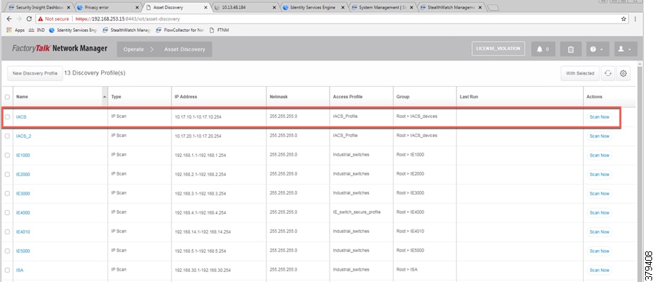
As shown in the first row of Figure 4-1, IACS profile is performing an IP scan for the IP address range 10.17.10.1 - 10.17.10.254. The Access_Profile used for this scan is IACS_PROFILE (explained in the next section) and all these devices are attached to a group called IACS_devices (also explained in the section below).
Configuring Access Profiles
The Access Profile is a template that has the common configuration parameters: username, password, and the SNMP community string information. When a group of devices use a different set of parameters, then a separate Access Profile can be defined. The Access Profile created in this section is tied to the Discovery Profile. Figure 4-2 shows the details of an Access Profile named IACS_PROFILE.
Figure 4-2 Configuring the Access Profile

Asset Inventory
NMT maintains list of devices that it has discovered in the Asset Inventory. Each element of the Asset Inventory provides information such as an IES that is attached to an IACS asset, the device type (Controller, IO, and other device types), the interface between the IACS device and the IES, the protocol used to communicate with the IACS asset, IP address of the IACS asset, group information of the device, vendor information, and so on. There are filters available for OT control system engineers to search for devices based on different criteria. Figure 4-3 shows a list of controllers that support the CIP protocol. As shown in Figure 4-3, NMT displays important information about the IACS asset.
Figure 4-3 Asset Inventory of NMT

Group Management
Managing devices in separate groups not only simplifies the management of devices, but can also allow an OT control system engineer to influence an access policy for IACS assets. Figure 4-4 shows three groups that have been created based on the Cell/Area Zone topology.
Figure 4-4 Topology Diagram for FTNM

Configuring Security Tags
NMT release 1.4 and greater supports another important feature called security tags. An OT control system engineer can tag a device with a security tag. This feature allows an OT control system engineer to express an intent for an IACS asset (for more information about intent, see OT Managed Remote User (Employee or Partner) Accessing from (Enterprise or Internet) to a Network Device or an IACS Asset in Chapter 5, “Implementation of Use Cases”). Figure 4-5 show how security tags can be created. In Figure 4-5 the security tag of 10 has been assigned to two devices.
Figure 4-5 Configuring Security Tags in NMT

Licensing
NMT comes up with a base license that allows an OT operator to create Asset Discovery Profiles, scan the assets, and export the asset attributes to Cisco ISE. To perform these tasks, no special license is required. However, if the OT operator would like to have access to features of NMT for managing IES devices, then licenses must be purchased.
Configuring Cisco ISE
This section gives details on how to configuring Cisco ISE for the following components:
- Distribution Deployment
- pxGrid between Cisco ISE and NMT
- Enabling Profiling and configuring different profiling policies
- TrustSec Configuration
Distribution Deployment
As mentioned in the Cisco ISE Deployment Considerations, distributed deployment of ISE was chosen for this CPwE Network Security CVD DIG and also validated with the distribution deployment model. Figure 4-6 shows how different instances of ISE were used to achieve the distribution model:
Figure 4-6 Devices Present in Distributed ISE Deployment

Table 4-1 describes the role for each of the ISE instances.
|
|
|
|---|---|
Primary role is for Administration and Secondary role is for Monitoring |
|
Primary role is for Monitoring and Secondary role is for Administration |
|
As shown in Table 4-1 , cidm-ise-2 is the PAN node for this design, and all the administration tasks such as configuration of network devices, authentication policies, authorization policies, certificate management, checking logs and all other tasks must be done on this PAN. No configuration is done on the PSN nodes. The network access devices will use the IP address of the PSN node for RADIUS and CTS configuration. The network access devices must not point to the PAN node. In this CPwE Network Security CVD DIG, when displaying information on navigation it would be mentioned as (ISE admin web), which means configuration is done on the PAN node.
Configuring pxGrid between Cisco ISE and NMT
Enabling pxGrid registration between NMT and Cisco ISE involves a couple of steps. The pxGrid framework needs certificate-based authentication. So, both Cisco ISE and NMT need to present their certificates to each other for the registration process to be completed. The next sub-sections describe the following steps that need to be performed:
Enabling pxGrid in Cisco ISE
The pxGrid service needs to be enabled in the Cisco ISE. To enable pxGrid service, go to (ISE admin web)—>Deployment. Figure 4-7 shows how to enable pxGrid services in the Cisco ISE.
Figure 4-7 Enabling pxGrid Service in the Cisco ISE
Enabling pxGrid Service in Cisco ISE Certificate
For pxGrid registration between NMT and Cisco ISE to work, the root certificate for Cisco ISE needs to be exported into NMT. This step is done on the PAN PRI. The first step is to pick a certificate in (ISE admin web) —> Administration—>Certificate—>System Certificate and then enable pxGrid services in that certificate. Figure 4-8 shows pxGrid service enabled for a self-signed certificate in Cisco ISE.
Figure 4-8 Cisco ISE Certificate with pxGrid Services Enabled

Exporting the Cisco ISE Certificate
The next step is to export the above certificate so that the exported certificate can be imported to NMT. After the export option is selected, the file will be downloaded into the local computer. The downloaded certificate needs to be saved and is used in the NMT pxGrid registration to ISE, which is shown in Configuring pxGrid on NMT.
Figure 4-9 Exporting Cisco ISE Certificate

Downloading NMT Certificate
The self-signed certificate of the NMT must be exported from the NMT and must be imported to Cisco ISE as a trusted certificate. This step is mandatory because for the Cisco ISE to trust NMT, it must know the root certificate of NMT. Figure 4-10 shows the option for downloading the NMT certificate. When Download.pem NMT certificate is selected, the certificate is downloaded to the computer which must, in the next step, be imported into Cisco ISE.
Figure 4-10 Download NMT Certificate
Importing NMT Certificate to Cisco ISE
The NMT certificate must be imported into:
(ISE admin web)—>Administration—>Certificates—>Trusted Certificates store
Figure 4-11 shows the status on Cisco ISE after the NMT certificate is imported into the Cisco ISE Trusted Certificates list.
Figure 4-11 Import NMT Certificate to Cisco ISE

Configuring pxGrid on NMT
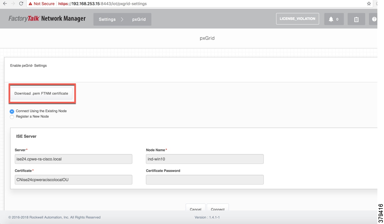
On the NMT, pxGrid registration needs to be performed. Figure 4-12 shows the parameters that must be provided for successfully registering NMT to Cisco ISE. The server information is the FQDN name of the Cisco ISE server and it must be resolvable by the NMT either by using DNS or using a local host to IP address mapping in the NMT server. The Node Name can be any name that is easier to remember and the Certificate field is the certificate that was downloaded in the previous step. When the connection is initiated from NMT for pxGrid set up, the acknowledgment must say that pxGrid registration is successful. If no response is received, then further troubleshooting must be performed. When the registration is successful, the NMT will be listed under the web-clients list in Cisco ISE, which is shown in Figure 4-13.
Figure 4-12 pxGrid Registration in NMT

Approving NMT Client in Cisco ISE
The NMT web-interface may report that the registration between NMT and Cisco ISE is successful. But the IT security architect must approve the NMT registration request on Cisco ISE as shown in Figure 4-13.
Figure 4-13 Approving NMT Client in Cisco ISE

Profiling in Cisco ISE
Profiling in Cisco ISE happens using several probes such as RADIUS, DHCP, SNMP, and so on. Cisco ISE can profile different types of assets, but this CPwE Network Security CVD DIG focuses on profiling IACS assets using pxGrid probe.
Enabling pxGrid Probe in Cisco ISE
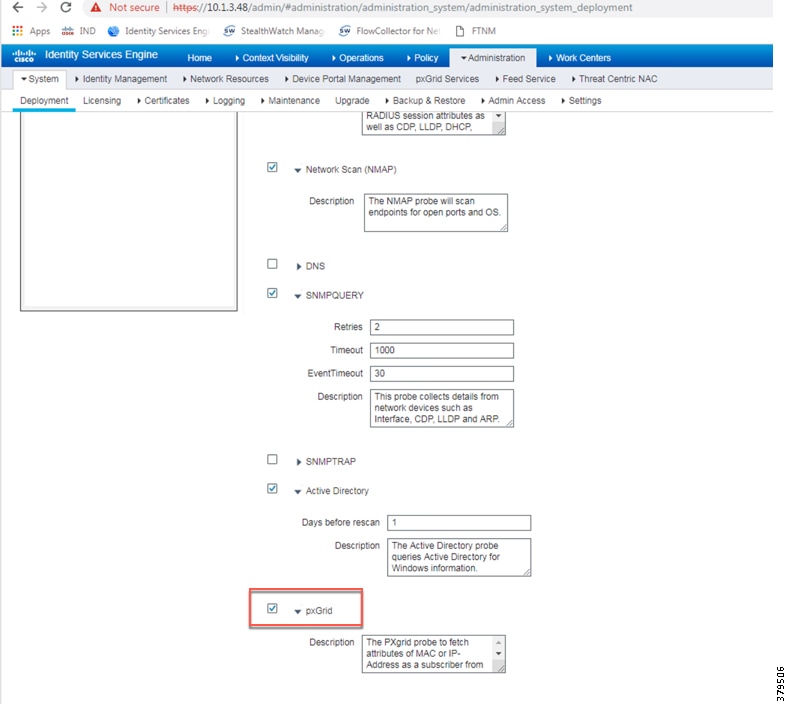
To discover IACS assets, Cisco ISE uses pxGrid probe to discover and profile IACS assets. To enable pxGRID probe, navigate to (ISE admin web) —> Administration —> Deployment and then select the appropriate PSN (ise24 in this CPwE Network Security CVD) and then select the profiling tab where an option is provided to enable the pxGRID probe. Figure 4-14 shows how to enable pxGrid probe in Cisco ISE.
Figure 4-14 Enabling pxGrid Probe in Cisco ISE
Creation of User Groups
In this CPwE Network Security CVD DIG some example groups were create to explain how OT control system engineers and IT security architects can create groups of devices and profile them. Table 4-2 gives an example on different roles for IACS assets in a plant-wide architecture. The description in Table 4-2 shows the permission needed for a particular user group. For example, a device classified as Level_3 group is a device that needs access to all the devices in the plant-wide architecture. Similarly, a device classified as Level_0_IO device has access to devices that are located in a particular Cell/Area Zone. The main intent of the Table 4-2 access policy example is only to provide a reference example for designing an access policy using TrustSec in a plant-wide network.
Profiling Policies in Cisco ISE
Profiling policies in Cisco ISE are used to profile IACS assets. This section shows how to create different profiling policies based on Table 4-2 .The profiling policies shown here are meant as an example and should not be considered a method for the actual deployment.
Level_1_controller Policy
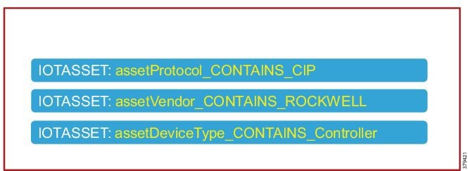
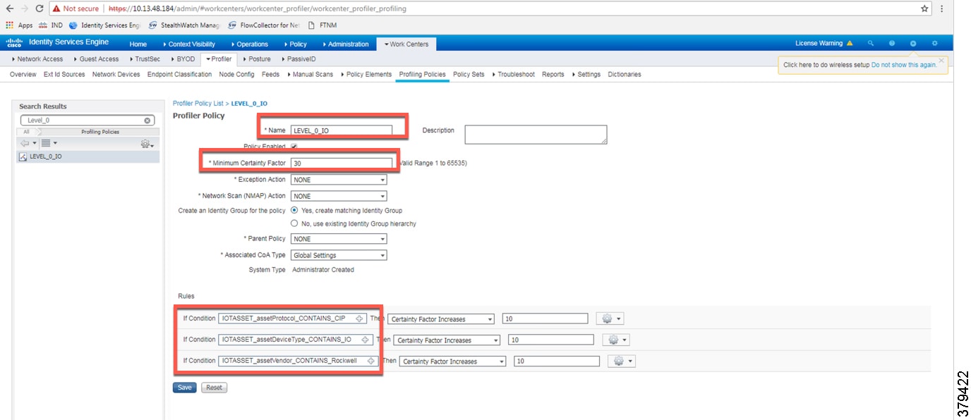
This policy is used to profile an IACS asset which is a controller. The key attributes used to profile this device are shown in Figure 4-15. As shown in Figure 4-15, the IOTASSET dictionary is used to match different conditions like protocol, assetVendor, and assetDeviceType. The values for the attributes assetVendor and assetDeviceType are obtained by ISE via the integration to NMT. When a new IACS asset is discovered by NMT, it provides the details of the asset to Cisco ISE and this information is used to fill in the attribute values of the IOTASSET dictionary.
Figure 4-15 Attributes Used to Profile a Controller
When a match is found for each condition, the certainty of the device matching the profile increases. If a profiling policy matches all three conditions, then the certainty factor goes higher. There is an option to specify the minimum certainty factor. For example, in Figure 4-15, if each condition match gives a certainty factor of 10, then if all three conditions match the certainty factor becomes 30. The profiling policy for the previous example can be made stringent by only allowing a device to be profiled if it gets certainty factor of 30 or it can be made very lenient by classifying it as Level_1_Controller if it matches at least one of the conditions. In this CPwE Network Security CVD DIG, the stringent choice was made when classifying a controller. Figure 4-16 shows the Level_1_controller policy defined in Cisco ISE.
Figure 4-16 Level_1_controller_policy in Cisco ISE
Level_0_IO_policy
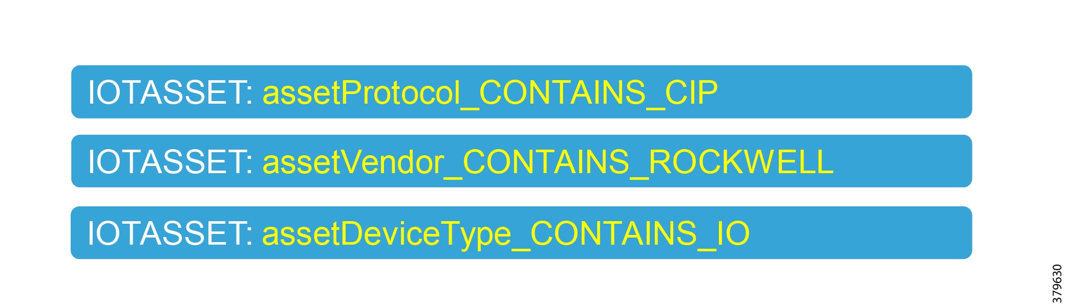
The Level_0_IO_policy is used to profile I/O assets, which usually have a role which is very local to the Cell/Area Zone and will rarely have access outside the Cell/Area Zone. Figure 4-17 shows the high level idea for Level_0_IO_policy and Figure 4-18 shows the profiling policy used to profile I/O IACS assets.
Figure 4-17 High Level Attributes for Level_0_policy

Custom Attributes
Cisco ISE uses attributes defined in a dictionary to restrict access to IACS assets and other devices. In Figure 4-16 and Figure 4-18, IOTASSET dictionary was used to match attributes that were meant to match IACS assets. In addition, Cisco ISE allows a user to create custom attributes that a user can specify. A combination of pre-defined attributes provided by Cisco ISE along with user attributes allows an IT security architect to create more granular policies. In this CPwE Network Security CVD DIG, two custom attributes—assetGroup and assetTag—were used to create more granular policies. These attributes were sent from NMT to Cisco ISE using the pxGrid API in addition to the normal attributes. Configuring security tags shows how an OT control system engineer can use NMT to define security tags; this tag information is seen in Cisco ISE as assetTag. Figure 4-19 shows how to define custom attributes in Cisco ISE at (ISE admin web) —> Administrator—>Identity Management—>Settings.
Figure 4-19 Enabling Custom Attributes in Cisco ISE
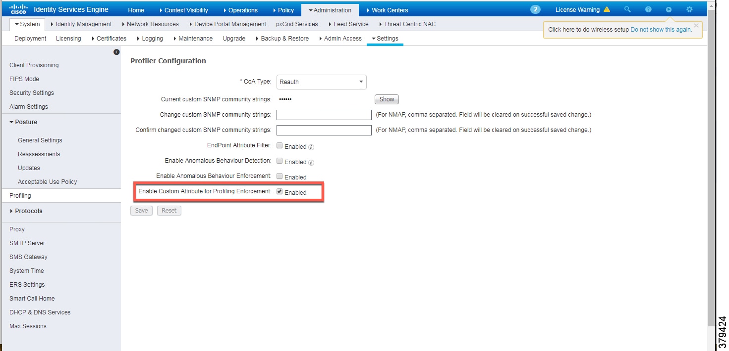
Figure 4-20 shows how to define the custom attributes by going to (ISE admin web) —> Administration—>Identity Management—>Endpoint Custom Attributes.
Figure 4-20 Custom Attribute Examples

Level_3_policy
Level_3_policy is used to profile IACS assets that need to access IACS assets across the Cell/Area Zones. For example, a Level_1_Controller in a Cell/Area Zone may need to access another Level_1_Controller in another Cell/Area Zone. This access may not be needed for all the Level_1_Controllers, but only for a few of them. Cisco ISE profiles a device as a Level_1_Controller based on the device attributes defined in the IOTASSET dictionary. There is a need for an additional attribute along with the normal attributes to classify a Level_1_Controller as Level_3. Custom attributes that were discussed in the previous section could be used in conjunction with the device attributes to classify as Level_3. Figure 4-21 shows the general idea of classifying the device as Level_3.
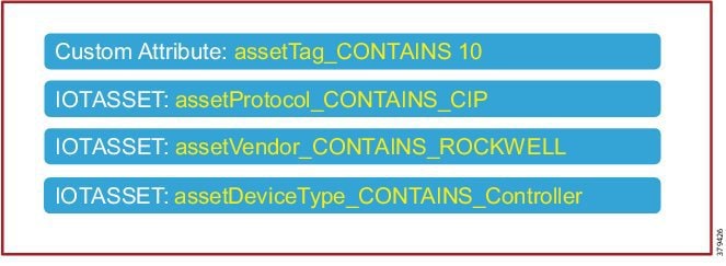
The assetTag attribute is a custom attribute that was used in addition to the device attributes such as assetProtocol, assetVendor, and assetDeviceType. The minimum certainty factor now increases to 40 because four attributes used to match an IACS asset as Level_3 and each attribute by default has a certainty factor of 10. To understand how to create an assetTag in NMT, refer to Figure 4-5.
Remote_Access
This profiling access policy is used to classify IACS assets that are given access by a remote user to access the device. As shown in OT Influenced Remote Access—For Example Downtime in “CPwE Network Security Overview,” a remote user connects to a jump box in IDMZ (for best practices, see Appendix A, “References” for links to the CPwE IDMZ CVD DIG), then accesses a remote desktop server in the Industrial Zone, and from this remote desktop server a connection is made to an IACS asset that needs to be accessed. For example, an IACS asset in Cell/Area Zone currently classified as a Level_1_Controller needs to be accessed by the remote desktop server in the Industrial Zone. The current policy is that no IACS asset can be accessed by the remote desktop server unless the IACS asset is classified as Remote_Access. To change a Scalable Group Tag for an IACS asset, a Change of Authorization (CoA) must occur. NMT allows a control system engineer to express operational intent by changing the assetGroup of the IACS asset. Then Cisco ISE would re-profile the IACS asset, issue CoA to the IACS asset, and push a new Scalable Group Tag to the IACS asset. In this CPwE Network Security CVD DIG, assetGroup ='Remote' was defined in NMT as a group where IACS assets that need Remote_Access are placed by the OT control system engineer. Figure 4-22 illustrates the profiling policy used to match Remote_Access.

Note![]() When a new SGT is assigned to an IACS asset, there is a loss of connectivity for a few seconds, during which time no application is able to access the IACS asset.
When a new SGT is assigned to an IACS asset, there is a loss of connectivity for a few seconds, during which time no application is able to access the IACS asset.
Figure 4-22 Profiling Access Policy for Remote Access

In this CPwE Network Security CVD DIG, only the custom attribute assetGroup was used to classify the device. As this policy is meant for all IACS assets, only the assetGroup was used to profile the device. The IT security architect can add additional matching conditions, for example, assetDeviceType="Controller" and assetGroup ="Remote".
Configuring TrustSec in Cisco ISE
This section provides configuration details for different components that need to be configured on Cisco ISE to support TrustSec in IES and the Cisco Catalyst 3850.
Adding IES to Cisco ISE
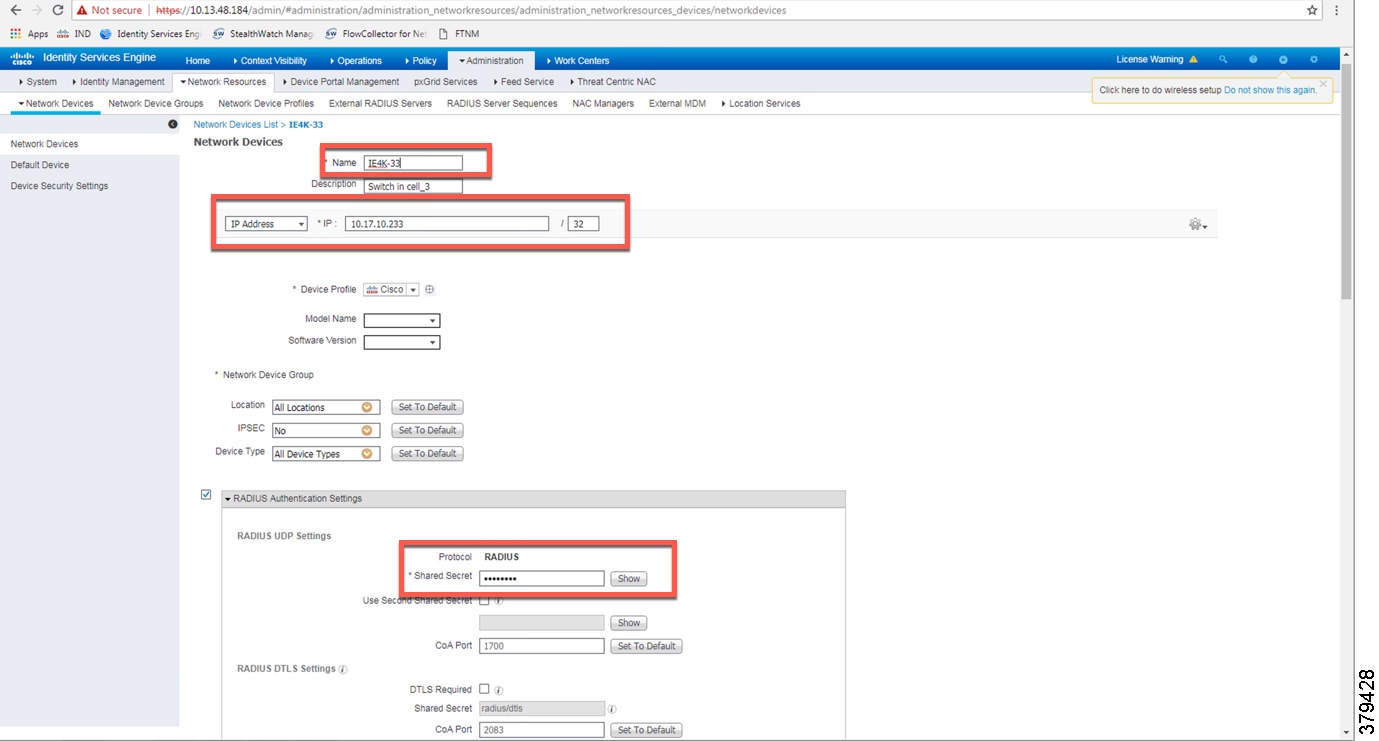
For Cisco ISE to assign Scalable Group Tags to IACS assets, IES details such as IP address and radius pre-shared secret key must be configured on Cisco ISE. Navigate to (ISE admin web) —> Administration —> Network Devices to configure the IES details. Figure 4-23 shows the information needed to establish successful radius configuration between an IES and Cisco ISE.
Figure 4-23 IES Radius Configuration
CTS Configuration on Cisco ISE
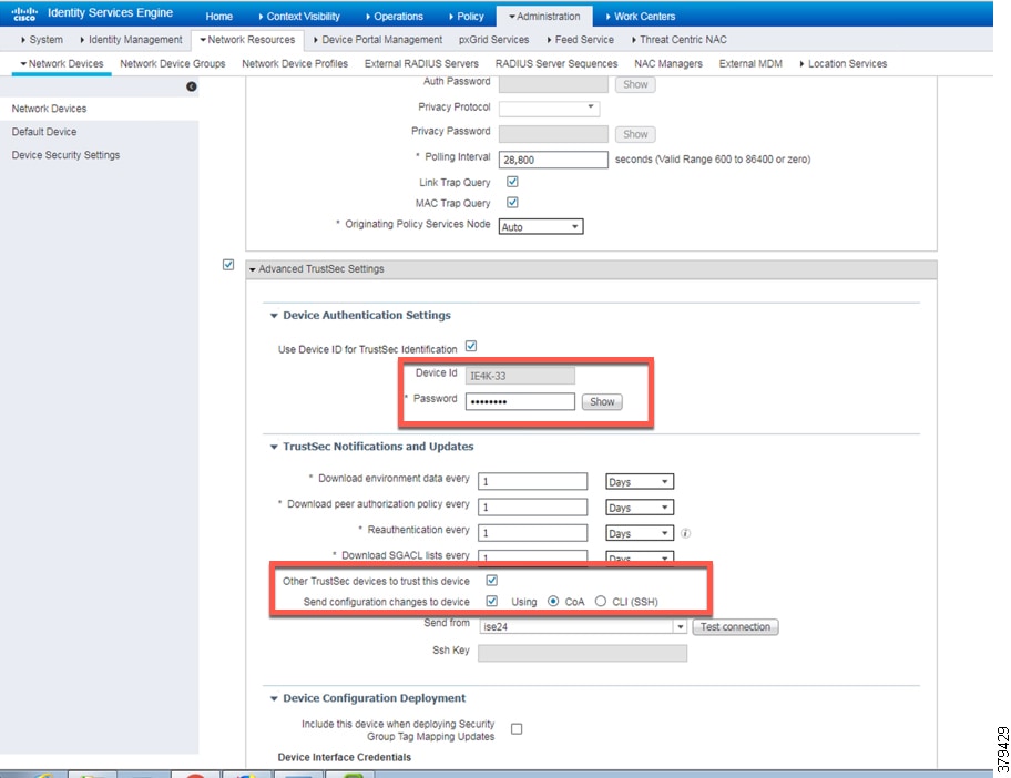
In the same frame as show in Figure 4-23. the CTS configuration for IES must be configured, as shown in Figure 4-24.
Figure 4-24 CTS Configuration for IES
Configuring SXP in Cisco ISE
This section describes on how to enable SXP in Cisco ISE and configure SXP peers in Cisco ISE.
Enabling SXP Service in Cisco ISE
SXP service is enabled in Cisco ISE by going to (ISE admin web) —>Administration—>Deployment.
Figure 4-25 Enabling SXP Service in Cisco ISE

Configuring SXP Peers
The IES are configured as Speakers and Cisco ISE is enabled as a Listener. To configure SXP peer, the source and the destination IP addresses must match at the IES and the Cisco ISE. In Cisco ISE, a default configuration template can be used to fill in the rest of the parameters such as password. The location for configuring SXP can be found by going to (ISE admin web) —>Work Centers—>SXP.
Figure 4-26 Configuring SXP Peers in Cisco ISE

Configuring SXP Default Parameters
The default parameters can be configured at (ISE admin web) —>Work Centers—>TrustSec—>Settings.
Figure 4-27 Configuring SXP Default Parameters

Configuring SGT Components
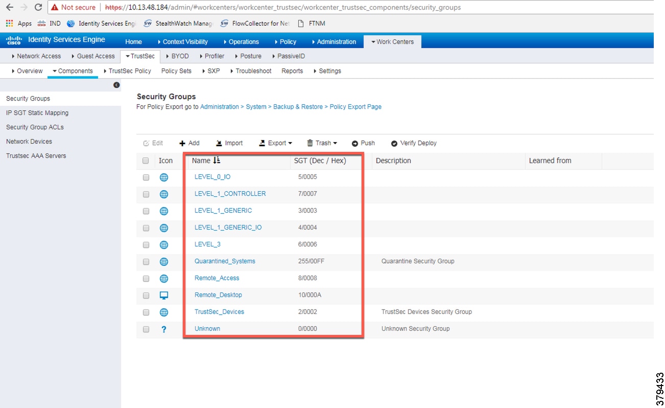
IACS assets need to be grouped based on the device function such as controller, IO, HMI, and so on. Each device when it is profiled, authenticated, and authorized has a SGT assigned to the device as an end result. The SGT assignment is done by Cisco ISE and the list of SGTs need to be defined by the IT security architect in Cisco ISE. In this CPwE Network Security CVD DIG, a few device profiles were tested to illustrate how SGT design could be done in a deployment. Creation of User Groups gives an overview on the user groups in a CPwE network architecture. Figure 4-28 shows an example of SGT assignment in Cisco ISE, which is located at (ISE admin web) —>Work Centers—>TrustSec—>Components.
Figure 4-28 Configuring SGT Components in Cisco ISE
Configuring TrustSec Access Policy Matrix
This section describes how to design a policy matrix for Cisco ISE. Based on the example illustrated in Table 4-2 , the following are policy matrix rules:
- IACS assets or any other devices that are assigned with the SGT group of Level_3 are allowed to access all the devices in the plant-wide network.
- IACS assets with SGT value of Level_1_Controller are allowed to access only the devices in the same Cell/Area Zone.
- IACS assets with SGT value of Level_0_Controller are allowed to access only the devices in the same Cell/Area Zone.
- IACS assets with Remote_Access are allowed to communicate with another device assigned with SGT value of Remote_Desktop and Level_3 (because Level_3 has access to all the devices).
Figure 4-29 shows the TrustSec Access Policy Matrix.
Figure 4-29 TrustSec Access Policy Matrix
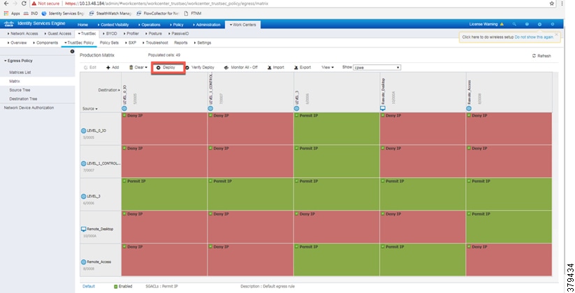
As shown in Figure 4-29, Level_3 Controller is allowed to communication with the all the IACS assets, however Level_1_Controller and Level_0_IO can only communicate if they are present in the same Cell/Area Zone. After defining the TrustSec Policy in the ISE, it is downloaded to all IES and the distribution switch (Cisco Catalyst 3850) by selecting the “Deploy” option, as shown in Figure 4-29. The TrustSec policy matrix can become larger and it may be difficult to view the entire policy on a single screen. To prevent that problem, an option exists to filter the view that will display the matrix that has desired SGTs only. The Show box on top of the screen will enable that functionality and requires the user to create a custom view.
Authentication Policy
802.1X authentication policy involves three parties:
- The supplicant—A client device that wishes to attach to the network.
- The authenticator—A networking device that accepts authentication requests from the client and sends them to the RADIUS authentication server.
- The authentication server—One that validates a client’s identity and sends back the success or failure RADIUS message.
In this CPwE Network Security CVD DIG, the supplicant is the IACS asset, the authenticator is the IES, and the authentication server is ISE.
Authentication policies are used to define the protocols used by Cisco ISE to communicate with the IACS assets and the identity sources to be used for authentication. Cisco ISE evaluates the conditions and, based on whether the result is true or false, applies the configured result. The authentication protocol tested in this CPwE Network Security CVD DIG is called MAC Authentication Bypass (MAB). MAB uses the MAC address of a device to determine what kind of network access to provide. This protocol is used to authenticate end devices that do not support any supplicant software in them, such as 802.1X EAP-TLS, EAP-FAST, and so on. For more information about MAB, see: https://www.cisco.com/c/en/us/products/collateral/ios-nx-os-software/identity-based-networking-services/config_guide_c17-663759.html
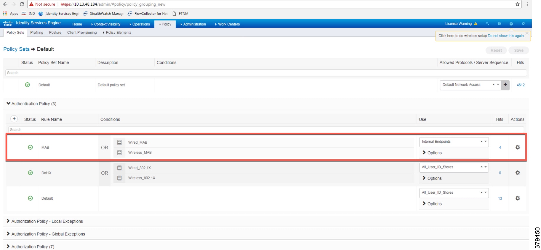
The authentication policy used in the Cisco ISE for this CPwE Network Security CVD DIG checks the protocol and the Identity Store as Internal Endpoints. To configure the authentication policy, navigate to (ISE admin web) —> Policy —> Policy Sets —> Default as shown in Figure 4-30, and select the arrow on the right to configure the authentication policy, as shown in Figure 4-31.
Note![]() In the example shown in Figure 4-31, the default authentication policy set was used. In case the real deployment has a different authentication policy set, then the IT Security Architect must select the correct authentication policy set.
In the example shown in Figure 4-31, the default authentication policy set was used. In case the real deployment has a different authentication policy set, then the IT Security Architect must select the correct authentication policy set.
Figure 4-30 Navigation to Configure Authentication/Authorization Policy
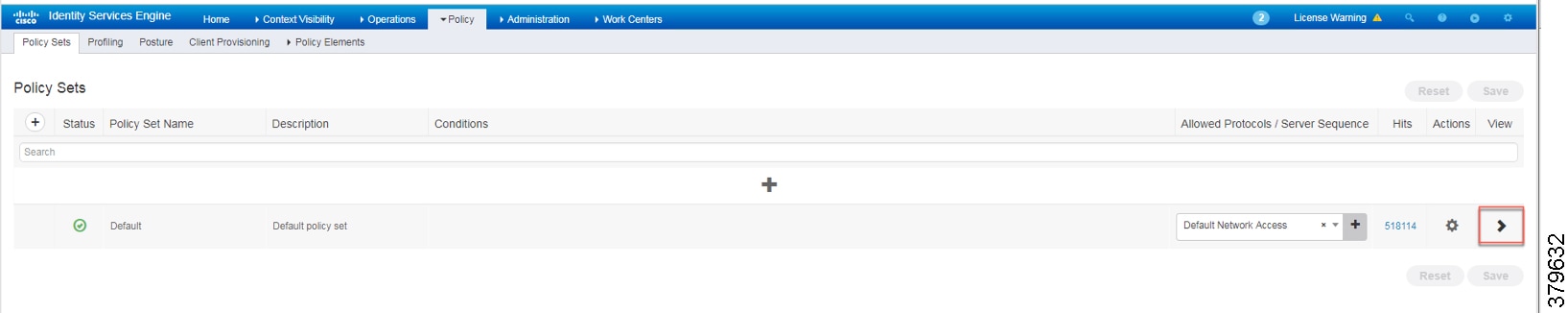
Figure 4-31 ISE Authentication Policy
Authorization Policies
Authorization policies are critical to determine what the user is allowed to access within the network. Authorization policies are composed of authorization rules and can contain conditional requirements that combine one or more identity groups. The permissions granted to the user are defined in authorization profiles, which act as containers for specific permissions.
Authorization profiles group the specific permissions granted to a user or a device and can include attributes such as an associated VLAN, ACL, or a SGT. This CPwE Network Security CVD DIG uses SGT to grant permissions to an IACS asset. Configuring TrustSec Access Policy Matrix describes how the Policy Matrix was designed in the CPwE Network Security CVD DIG. When an IACS asset is authenticated and as part of the authorization policy, an appropriate SGT is assigned to the IACS asset. The TrustSec Policy Matrix determines the permissions associated with each IACS asset. Figure 4-32 shows the high-level steps when an IACS asset is connected to the network. To configure the authorization policy navigate to (ISE admin web) —> Policy —> Policy Sets —> Default and then select Authorization Policy.
Figure 4-32 AAA for an IACS Asset

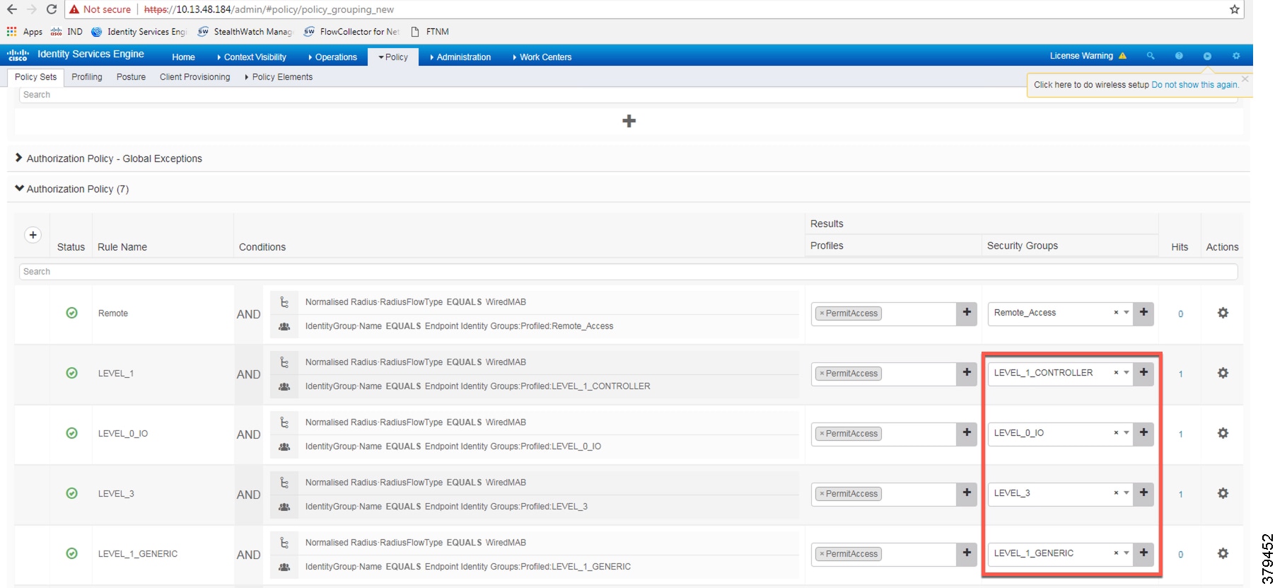
The default policy can be designed based on how stringent the requirement is. One option is to assign a default SGT like LEVEL_GENERIC and classify devices that do not meet any of the authorization policy conditions. Or there could be a stringent design where, if an IACS asset is not being profiled by any of the existing conditions, then deny access to the network for that IACS asset. Figure 4-33 shows the authorization table for this CPwE Network Security CVD DIG.
Figure 4-33 Authorization Policy Conditions
Configuring IES
This section provides the configuration details for the IES in a CPwE network architecture. The configuration of key features deployed in the IES, such as TrustSec, NetFlow, and Radius server, are described below.
Configuring RADIUS AAA
Each IES must be configured to communicate with the Cisco ISE AAA server for authorizing IoT devices, users, and other systems. The AAA server shown in this configuration is pointing to the PSN node. The following configurations are performed via the command line interface (CLI) of the device.
Step 1![]() Enter configuration mode. At the global level specify the interface that has the IP address configured in Cisco ISE that will be used to source authentication requests. Enable AAA.
Enter configuration mode. At the global level specify the interface that has the IP address configured in Cisco ISE that will be used to source authentication requests. Enable AAA.
Step 2![]() Configure Change of Authorization (CoA):
Configure Change of Authorization (CoA):
Note![]() This configuration done on the IES device must match the configuration done on Cisco ISE. Refer to Figure 4-23.
This configuration done on the IES device must match the configuration done on Cisco ISE. Refer to Figure 4-23.
Step 3![]() Configure the radius server for TrustSec. In this CPwE Network Security CVD DIG, the name for the list is cts_list and this name should be tied to the aaa authorization network command shown in Step 1:
Configure the radius server for TrustSec. In this CPwE Network Security CVD DIG, the name for the list is cts_list and this name should be tied to the aaa authorization network command shown in Step 1:
Step 4![]() Configure the following RADIUS server attributes:
Configure the following RADIUS server attributes:
Step 5![]() Configure the RADIUS server, IP address, and shared secret that was entered in Cisco ISE:
Configure the RADIUS server, IP address, and shared secret that was entered in Cisco ISE:
Note![]() This configuration done on the IES device must match the configuration done on Cisco ISE. Refer to Figure 4-24.
This configuration done on the IES device must match the configuration done on Cisco ISE. Refer to Figure 4-24.
Step 6![]() Configure the AAA group name for RADIUS and specify the server created in step 5:
Configure the AAA group name for RADIUS and specify the server created in step 5:
Step 7![]() Globally enable port-based authentication:
Globally enable port-based authentication:
Configuring Port-based Authentication
On the IES, the following configurations enable port-based authentication. Configure each interface that will have an endpoint device connected. For MAB and Dot1x methods to co-exist and function as expected, the order and priority must be properly specified as referenced in this application note:
Configuring MAB
http://www.cisco.com/c/en/us/products/collateral/ios-nx-os-software/identity-based-networking-service/application_note_c27-573287.html
Add the following configuration to the interfaces where the IACS assets could be attached. In this CPwE Network Security CVD DIG, authentication open was applied to the port to ensure that the device remains connected even if for some reason the port is unable to authenticate to the RADIUS server. The default behavior of the port-based authentication is to block access to the network. By enabling authentication open, the port is not shut down and the IACS asset is able to communicate in the network by using the IP address assigned to it.
Configuring SDM Templates on IES
SDM templates will allow an OT control system engineer to prioritize resources for different features enabled on an IES. In this CPwE Network Security CVD DIG, the routing template is required to support SGT assignment on IES. To enable SDM mode to be “routing”, the following steps must be completed:
Configuring CTS Credentials on the IES
Specify the Cisco TrustSec device ID and password for the switch to use when authenticating with Cisco ISE and establishing the PAC file. This password and ID must match the Cisco ISE Network Devices configuration specified earlier in Figure 4-24.
Configuring SXP Tunnel on an IES
The SXP tunnel between Cisco ISE and an IES must be established because the SGT binding information (SGT value -IP address) should be sent to Cisco ISE, which would push this information to the enforcement point (Cisco Catalyst 3850). The following is the configuration of the SXP tunnel on the IES:
Configuring NetFlow on IES
Enabling NetFlow on an IES has three components: a Flow Record, a Flow Exporter, and a Flow Monitor. After all three components (explained below) have been configured, the Flow Monitor is applied to a physical interface.
Flow Record
A Flow Record defines the information that will be gathered by the NetFlow process, such as packets in the flow and the types of counters gathered per flow. Custom flow records specify a series of match and collect commands that tell the Cisco device which fields to include in the outgoing NetFlow record.
The match fields are the key fields, meaning that they are used to determine the uniqueness of the flow. The collect fields are extra information that is included in the record in order to provide more detail to the collector for reporting and analysis. When a Flow Record is defined, all of the flow data traffic that enters (ingress) or leaves (egress) the device is captured.
In configuration mode, create ingress or egress flow records using the appropriate interface direction commands. In this CPwE Network Security CVD DIG, traffic was captured on the ingress interface of the IES to capture the traffic generated by the IACS assets.
This configuration includes required as well as optional flow record fields needed by Stealthwatch.
Step 1![]() Create Ingress Record, which in this CPwE Network Security CVD DIG is called a StealthWatch_Record:
Create Ingress Record, which in this CPwE Network Security CVD DIG is called a StealthWatch_Record:
Note![]() When the IES Device Manager was used to configure NetFlow on the ports by using the Stealthwatch template, then the command collect counter packets long was not applied to the IES device, and without this command, the Stealthwatch management console was not able to detect any flows coming from the IES device. To mitigate this behavior, the command collect counter packets long must be applied using CLI. If the IES CLI is used to configure NetFlow on the IES device, then the above mentioned configuration will work. This problem happens only when the Device Manager was used co configure NetFlow on the IES device.
When the IES Device Manager was used to configure NetFlow on the ports by using the Stealthwatch template, then the command collect counter packets long was not applied to the IES device, and without this command, the Stealthwatch management console was not able to detect any flows coming from the IES device. To mitigate this behavior, the command collect counter packets long must be applied using CLI. If the IES CLI is used to configure NetFlow on the IES device, then the above mentioned configuration will work. This problem happens only when the Device Manager was used co configure NetFlow on the IES device.
Flow Exporter
The Flow Exporter defines where and how to send the NetFlow (Flow Records). In actuality a Flow Exporter defines a flow collector IP address and port as the destination and in this case the Stealthwatch Flow Collector is the destination.
Flow Monitor
A Flow Monitor describes the NetFlow cache or information stored in the cache. Additionally, the Flow Monitor links together the Flow Record and the Flow Exporter. The Flow Monitor includes various cache characteristics such as the timers for exporting, the size of the cache, and, if required, the packet sampling rate (Sampled NetFlow/sFlow). As network traffic traverses the Cisco device, flows are continuously created and tracked. As the flows expire, they are exported from the NetFlow cache to the Stealthwatch Flow Collector. A flow is ready for export when it is inactive for a certain time (for example, no new packets received for the flow) or if the flow is long lived (active) and lasts greater than the active timer (for example, long FTP download and standard CIP I/O connections). There are timers to determine if a flow is inactive or if a flow is long lived. The times used in CPwE Network Security CVD are 30 seconds for inactive time out and 60 seconds for active time out.
Step 2![]() Create the Ingress flow monitor using the record and exporter created previously:
Create the Ingress flow monitor using the record and exporter created previously:
Step 3![]() Once the flow monitor has been created, it can be applied to all the access interfaces in an IES. Apply the flow monitor to an appropriate interface and the appropriate ingress/egress using input/output:
Once the flow monitor has been created, it can be applied to all the access interfaces in an IES. Apply the flow monitor to an appropriate interface and the appropriate ingress/egress using input/output:
Note![]() The IP flow monitor policy can be applied both in ingress and egress directions.
The IP flow monitor policy can be applied both in ingress and egress directions.
Configuring Distribution Switch—Cisco Catalyst 3850
As described in Segmentation—TrustSec in “CPwE Network Security Design Considerations,” the enforcement is moved to the distribution switch, no enforcement occurs in the Cell/Area Zone, and the East-West traffic flow, as explained in Traffic Flows in a Network in “CPwE Network Security Design Considerations,” is enforced at the distribution switch. This section describes the steps that need to be configured on the distribution switch to enable enforcement:
Configuring Radius Server
This is very similar to the configuration of IES, so refer to Configuring RADIUS AAA.
Configuring TrustSec
Configuring cts
The cts configuration is similar to the IES, so refer to Configuring CTS Credentials on the IES.
Configuring sxp
SXP configuration on the distribution switch is similar to the IES, so refer to Configuring SXP Tunnel on an IES.
Configuring IPDT
There is a change in the way Cisco Catalyst 3850 platforms are configured with device-tracking compared to the IES. In the Cisco Catalyst 3850, the device-tracking feature must be enabled, a device-tracking policy must be created, and this policy must be attached to the interface where the IP device-tracking needs to be enabled. In this CPwE Network Security CVD DIG, IP device-tracking is enabled on interfaces (Port-channel3) that are attached to IES interfaces.
Enforcement
In this CPwE Network Security CVD DIG, policy enforcement is done only on the Cisco Catalyst 3850 switch. To enable policy enforcement, the following commands must be enabled:
 Feedback