- CIP Sync
- Best Master Clock Algorithm
- Clock Types
- IES Clock Modes
- Time Scales
- Passing PTP Time through Boundary Clocks
- Reference Architecture 1—Redundant Star Topology
- Reference Architecture 2—Ring Topology
- PTP and MSTP Topologies Overview
- Recommended PTP Clock Hierarchy and Configuration
- Summary of Recommendations
CPwE Scalable Time Distribution Design Considerations
Reference Clocks
Reference clocks are the master time source for a plant-wide Industrial Automation and Control System (IACS) architecture. They are high precision clocks that are synchronized to a time standard such as International Atomic Time (TAI) or Coordinated Universal Time (UTC). TAI uses a system of hundreds of atomic clocks to accurately track time using International System of Units (SI) seconds. The SI second is a fixed measurement and is not compensated for changes in the notional period of the Earth.
UTC is the time scale people use to track time of day. UTC is based on TAI time and the SI second, however it uses leap seconds to align clocks with solar time. Periodically, leap seconds are added to adjust UTC time to the solar day. As of December 2015, UTC is 37 seconds behind TAI. All clocks in the system should synchronize directly or indirectly with the reference clock to provide a consistent view of time across the IACS application network infrastructure.
Global Navigation Satellite Systems
Global Navigation Satellite Systems (GNSS) such as the Global Positioning System (GPS) can be used to provide accurate reference time for network systems, for instance, time-critical IACS applications. GNSS navigation systems function by measuring the time delay between a receiver and one or more satellites. For these navigation systems to function, they must have highly accurate atomic clocks in each satellite. GNSS timeservers use these signals to synchronize their internal clock to the atomic clocks in the satellites. This allows the GNSS timeserver to provide very accurate synchronization to UTC. GNSS-based solutions also automatically handle leap seconds. Most GNSS receivers can output time as an NTP server. Some timeservers such as the 1756-TIME, Allen-Bradley Stratix 5410, and Cisco IE 5000 industrial Ethernet switches (IES) can function as a PTP grandmaster clock.
Network Time Protocol
Network Time Protocol (NTP) servers are commonly used to provide a reference clock for enterprise and IACS applications. NTP-based systems have an advantage because they do not require complicated satellite receivers to provide reference time for the system. However, the fact that the IACS application is synchronizing to a reference clock across a network limits the accuracy of the solution. NTP-based solutions will maintain an approximate synchronization to UTC and handle events like leap seconds.
Internal Clock
Internal clocks are free running oscillators inside IACS devices like Programmable Automation Controllers (PACs). Internal clocks need to be manually set to UTC by an administrator, such as an authorized OT engineer (e.g., Control Systems Engineer). Furthermore, all clocks drift over time and internal clocks do not have an automated mechanism for correcting drift. If clock accuracy to UTC becomes unacceptable due to drift or leap seconds, the administrator must manually correct the time in the clock.
Reference Clock Location
The location of the reference clock can have an impact on how well IACS devices in the IACS application synchronize to each other and to UTC. The ability of IES and IACS devices to synchronize across the network is generally impacted by factors such as bandwidth, latency, and jitter. These are some of the driving factors for the location of the reference clock. Availability is another consideration which may influence the placement of the reference clock. The reference clock should be positioned within the plant-wide IACS architecture so that the time synchronization architecture can meet the application requirements.
Internet
Protocols like NTP allow systems to synchronize to reference clocks located anywhere in the world. These reference clocks are hosted by a number of different types of organizations and the quality of the time service may vary widely:
Generally, reference clock sources offered by these organizations are reliable based on the limits of the NTP protocol. However, there are risks associated with using internet-based reference clocks. Most of these services are provided on a volunteer basis and could be changed or discontinued at any time. Furthermore, many public NTP servers do not provide any security to authenticate or verify the integrity of the time sources. Because of this, IT administrators should consider if the use of internet-based reference clocks is appropriate for their application needs. In addition, accessing internet-based NTP servers from the Industrial Zone is problematic since the traffic must flow through both the Industrial Demilitarized Zone (IDMZ) and the enterprise edge firewalls.
Enterprise Zone
Placing the reference clock in the Enterprise Zone places it directly under the authority of the IT organization. IT departments commonly deploy reference clocks to reliably synchronize their computer and network systems to a common time using NTP. Like internet-based NTP servers, these internal servers could be used as the time reference for IACS applications. However, as with internet-based sources it is important to consider the path between the IACS network and the enterprise time servers. If the Industrial Zone is connected to the headquarters site using a low bandwidth, high latency, and high jitter wide area network (WAN) link the accuracy and stability of time could be impacted. Furthermore, these deployments generally will not support applications where the reference clock must feed PTP time directly into the IACS application.
The Securely Traversing IACS Data across the Industrial Demilitarized Zone Design and Implementation Guide discusses passing NTP through the IDMZ.
https://literature.rockwellautomation.com/idc/groups/literature/documents/td/enet-td009_-en-p.pdf
Industrial Zone
From an IACS application perspective, placing the reference clocks directly in the Industrial Zone should provide the best quality of time synchronization and accuracy to UTC. This approach also allows the reference clock to source PTP time directly into the IACS application without converting NTP to PTP. The tradeoff is that a reference clock such as a GNSS receiver must be installed in the Industrial Zone.
Network Time Protocol
Network Time Protocol (NTP) is the Internet Engineering Task Force (IETF) standard for synchronizing clocks across the Internet and TCP/IP networks in general. NTP uses a hierarchical system of clocks to synchronize time across disparate hosts on the network. There are three roles for clocks in the NTP architecture:
- Servers—NTP servers act as a time source for one or more NTP clients.
- Clients—NTP clients synchronize their clocks to one or more servers.
- Peers—NTP peers allow two clocks to synchronize to each other. In essence, peers are clients and servers to each other.
These roles are not exclusive and any clock in the plant-wide IACS architecture can act as one or more of these roles. For example, an NTP server is generally a client to servers higher up in the NTP hierarchy.
NTP has limited provisions for authenticating timeservers. Most implementations support symmetric keys for authentication. Some recent implementations support the autokey security protocol. NTP authentication is outside the scope for this guide.
Some clients implement the Simple Network Time Protocol (SNTP). SNTP is a simplified version of the NTP daemon (computer program that runs as a background process) and generally has lower precision than the full NTP protocol.
NTP Hierarchy
The clock hierarchy (Figure 2-1) is divided into “stratum” where lower stratum numbers are closer to the reference clock. The reference clock is identified as the stratum 0 clock and is frequently a receiver for a GNSS such as a GPS, but could also be a radio receiver, atomic clock, or another precision time source. The stratum 0 clock is directly connected to the stratum 1 server and cannot be directly accessed across the network. The stratum 2 servers are the first to synchronize across the network using the NTP protocol. They are clients to several stratum 1 servers and are frequently peers to other stratum 2 servers. The stratum 3 servers are clients to the stratum 2 servers and may be peers to other stratum 3 servers and so on.
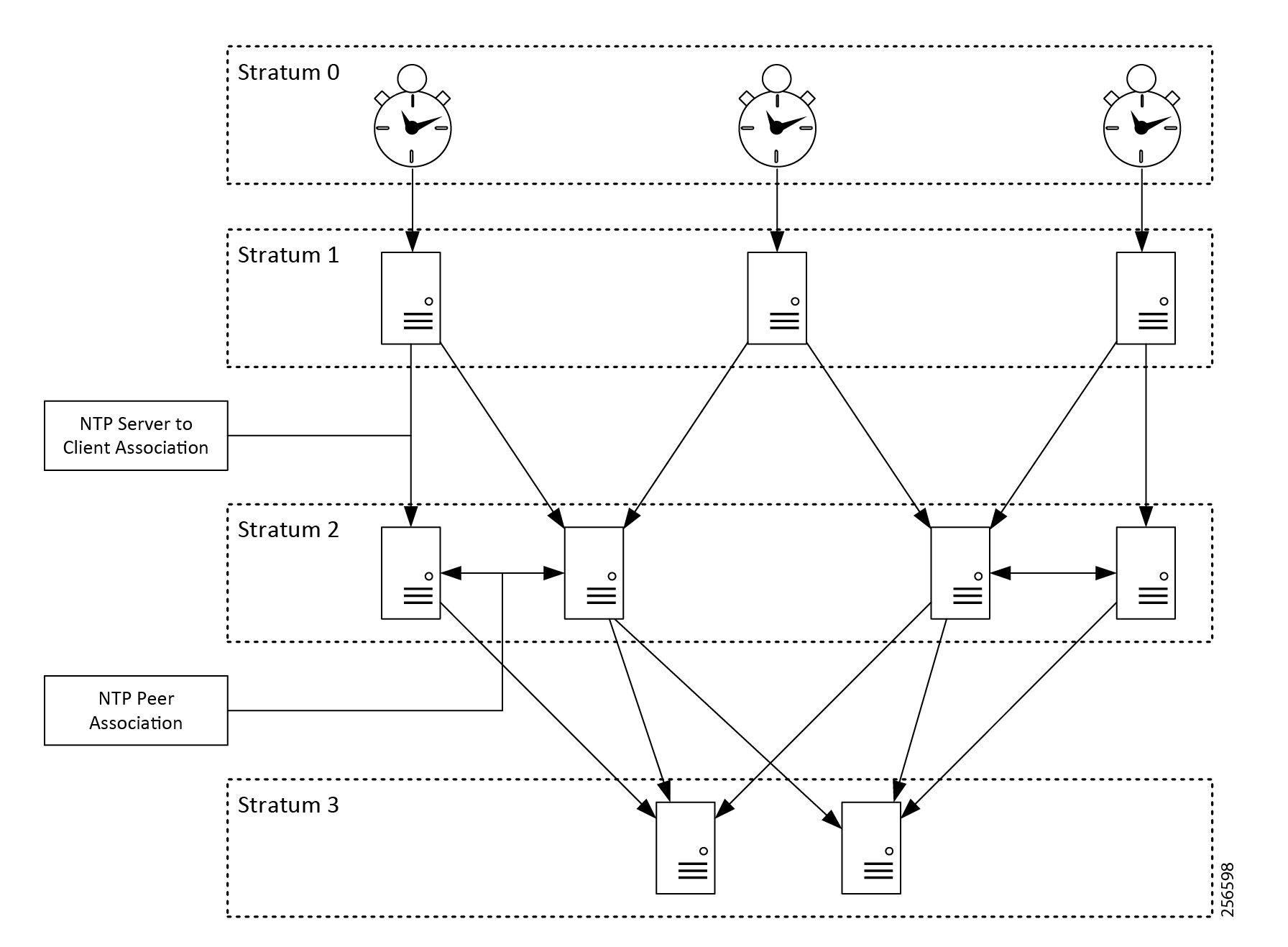
Generally, the ability of a client (e.g., IACS device) to synchronize its clock to the reference depends on its stratum level. Clocks with lower stratum numbers will be more tightly synchronized with the reference clock. NTP clocks will have limited accuracy to UTC. They are generally a better fit for IACS applications that can tolerate offsets to UTC of tens, if not hundreds, of milliseconds or even seconds.
However, there are a number of factors that can affect how precisely a client will synchronize to the reference clock.
- Network latency and jitter
- Asymmetric networks
- Number of hops between clocks
- Quality of the internal oscillator
- Operating system capabilities
The NTP clock algorithm supports associating with multiple servers. It will use the multiple inputs to provide better time synchronization of the local clock. The clock algorithm also sanity checks the associated servers. Clock updates from servers that are inconsistent with the pool are invalidated and discarded. Sanity checking reduces the risk of a bad clock source skewing in the NTP client.
Recommendations
Deploy two to four NTP servers in the Enterprise Zone to function as the central clocks for enterprise applications. Depending on the application requirements, these NTP servers could either be directly connected to reference clocks or synchronized to public servers on the Internet. If the decision is made to synchronize to public sources, each of these servers should be synchronized to two to four public sources. There should be some diversity in the public sources, so that a bad clock can be identified and removed from the clock pool. In addition, the Enterprise Zone servers should be peers to each other. Large organizations will likely have additional stratums of NTP servers within the organization to cascade time to the NTP clients. In cases where high accuracy NTP time is needed in the Industrial Zone, consider deploying a stratum 1 server within the Industrial Data Center (IDC) as part of Level 3 Site Operations.
Access to public NTP servers should be controlled at the enterprise edge firewalls. The goal is to have all NTP clients in the organization synchronize to the internal NTP servers. As such, access to public servers should be limited to the internal top-level NTP servers. Moreover, access should be limited to specific public servers that are trusted by the organization. Ideally, use authentication with any external NTP servers to reduce the risk of time synchronization being compromised.
Use NTP to synchronize the clocks in the switches, routers, firewalls, and other network infrastructure deployed in the IDMZ and Industrial Zone(s). Synchronizing time for these network devices is important so that syslogs from multiple network devices can be analyzed together to help troubleshoot system level faults.
Windows Domain Time
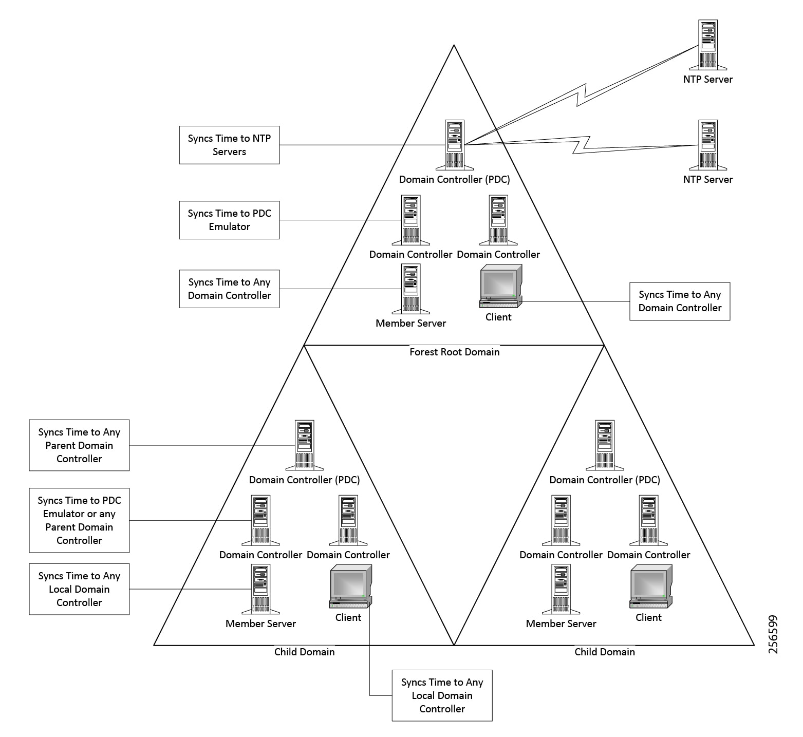
Windows Active Directory Domain Services require the domain members to synchronize their clocks with a common reference to support Kerberos authentication. The forest structure forms the basis for the time hierarchy in the Windows time model. A domain controller in the forest root is configured with the primary domain controller (PDC) emulator flexible single master operation (FSMO) role. This domain controller synchronizes its clock to one or more reliable NTP servers. The remaining domain controllers in the forest root domain synchronize their clocks to the PDC emulator. Any member servers or workstations in the forest root domain synchronize their clocks to any domain controller in the domain.
Each child domain also has a PDC emulator. The PDC Emulator in the child domains synchronizes its clock to any domain controller in the parent domain. The remaining domain controllers in the child domain synchronize their clocks to the local PDC emulator or any domain controller in the parent domain. Any member servers or workstations in the child domain will synchronize their clocks to the domain controllers in the local domain.
The same pattern continues for any additional child domains. Using the forest hierarchy for time synchronization ensures that all computer clocks in the domain synchronize within the limits of the Windows Time service.
Figure 2-2 Windows Time Hierarchy
Windows uses a customized version of NTP to maintain clock synchronization called MS-NTP. MS-NTP extends the NTP protocols to support authentication via Netlogon RPC. MS-NTP uses different versions of the NTP protocol depending on the version of the operating system.
|
|
|
|---|---|
Windows Time Service
Microsoft® designed the Windows Time Service to synchronize all clocks in the forest within five minutes to support Kerberos authentication. It is possible for the Windows Time Server to maintain accuracy better than five minutes, however there is no guarantee or requirement to support higher precision time.
Recommendations
- Configure the PDC emulator in the root domain to synchronize to two to four reliable NTP time sources.
- Windows domain controllers, member servers, and workstations should synchronize their clocks to the domain to ensure successful authentication.
- Enforce Windows time settings through group policy objects (GPO) to ensure correct configuration across the domains.
- Non-domain members should synchronize their time to a reliable NTP time source.
- Internet-based NTP servers may be considered acceptable given the relatively low accuracy of the Windows Time Service
Windows Time Service for High-accuracy Environments
Microsoft introduced an updated Windows Time Service in Windows Server 2016 and Windows 10 (build 1607). The new time service supports clock synchronization as accurate as 1 ms across the domain. The domain can consist of a mix of older and newer Windows Time Services, however only the Windows 10 and Server 2016 systems will achieve higher accuracy time. To achieve this level of accuracy Microsoft has developed a number of design restrictions based on the required accuracy. In the Microsoft model, the domain controllers act as time sources for the member servers and workstations. Therefore, the domain controllers need to be running Windows Server 2016 to support high-accuracy time. The member servers and workstations need to be running Windows Server 2016 or Windows 10 to achieve high-accuracy time.
https://docs.microsoft.com/en-us/windows-server/identity/ad-ds/get-started/windows-time-service/accurate-time
Recommendations
Microsoft has published requirements for maintaining 1 second, 50 millisecond, and 1 millisecond time synchronization across the forest. These requirements for the high accuracy Windows Time Service place some constraints on the Active Directory Domain Services design. The Active Directory Domain Services design for CPwE uses a single domain across the Enterprise and Industrial Zones. Assuming that this is also the forest root domain, it could be possible to achieve time synchronization with an accuracy that is close to 1 ms. This is assuming that the network infrastructure meets the requirements of the solution.
https://support.microsoft.com/en-us/help/939322/support-boundary-to-configure-the-windows-time-service-for-high-accura
It is important to consult with the IACS software vendor to ensure it is compatible with the latest versions of Windows server and workstation. For compatibility information for specific FactoryTalk® applications, see the Rockwell Automation® Product Compatibility and Download Center:
https://compatibility.rockwellautomation.com/Pages/home.aspx
Precision Time Protocol
The Precision Time Protocol (PTP) is defined by the IEEE 1588 standard and it is designed to provide nanosecond accuracy to clocks of IACS devices and IES in a network. PTP is designed specifically for industrial, networked measurement, and control systems. It is optimal for use in distributed IACS applications because it requires minimal bandwidth and little processing overhead.
The protocol operates in a hierarchical manner, establishing master-slave relationships among devices, where slaves will synchronize their clocks with a master clock. The IACS devices and IES maintain time synchronization by sending and receiving PTP event messages containing information that allows them to correct time differences between master and slaves.
The process that builds the clock hierarchy, determining what devices will be assigned as master or slave, is done by using the Best Master Clock Algorithm (BMCA). When a PTP-capable clock joins the network, it will listen to PTP messages called PTP announce messages. These messages will contain information such as time source, clock quality, and priority numbers. The BMCA runs continuously and uses the announce messages information to make these assignments and adjustments as necessary.
CIP Sync
There are a number of different solutions that utilize IEEE 1588 for time synchronization. This CPwE Time reference design focuses on IACS applications that use the ODVA, Inc. CIP Sync standard. CIP Sync is an extension of the Common Industrial Protocol (CIP) that establishes object models for the synchronization of time within an IACS application. CIP Sync can be used for various applications including sequence of events and distributed motion control (not included in CPwE Time) applications. CIP Sync uses the IEEE 1588 default profile and end-to-end transparent clocks.
EtherNet/IP devices are not required to implement the CIP Sync standard. It is important to select IACS devices (e.g., communications adapters and I/O modules) that support CIP Sync during the design, sizing, and selection phase of a project. Furthermore, it is important to verify the specifications for time stamping I/O modules to ensure that they meet the IACS application requirements. Integrated Architecture® Builder is a Rockwell Automation product that provides a means to select Rockwell Automation IACS devices and IES that support CIP Sync.
More information on Rockwell Automation Integrated Architecture Builder can be found at the following URL:
http://www.rockwellautomation.com/global/support/integrated-architecture-builder.page
Best Master Clock Algorithm
The Best Master Clock Algorithm (BMCA) is used to determine which IACS device or IES in a PTP domain has the best clock and should be the grandmaster clock for the IACS application. To accomplish this, the BMCA uses an ordered set of attributes to select the grandmaster clock, as shown in Table 2-2 .
|
|
|
|
|---|---|---|
User configurable value that prioritizes otherwise equal clocks |
||
The BMCA will always select the “best” grandmaster available on the network. However, in most cases it may be beneficial to use the priority1 and priority2 values to weight the election and force specific devices to become the grandmaster.
Clock Types
Ordinary Clock
An ordinary clock has a single PTP port. It functions as a node in the PTP topology and can be selected by the BMCA as a master or slave within the PTP domain. Ordinary clocks are the most common clock type in a PTP system because they are used as end nodes in the system. Typical examples of ordinary clocks in an IACS application are a Programmable Automation Controller (PAC) or an I/O device.
Grandmaster Clock
The grandmaster clock is the primary source of time in the PTP domain. Grandmaster clocks should have high quality oscillators and be synchronized to UTC.
Boundary Clock
A boundary clock is a multiport device (e.g., IES) that becomes a slave on one port. As a slave clock, the boundary clock synchronizes its internal clock to the master. The boundary clock then becomes a master to IACS devices connected to the other ports on the IES. Other clocks connected to these ports will become slaves to the boundary clock and synchronize to the boundary clock’s internal clock.
Transparent Clock
Transparent clocks compensate for latency across the network by inserting delay corrections into the PTP packets. There are two types of transparent clocks defined in the IEEE 1588 specification:
- End-to-end transparent clocks compensate for latency across a network by measuring how long IACS devices and IES in the network take to process and forward the PTP packets. These measurements are added to the correction field in the PTP packets.
Transparent clocks do not become nodes in the PTP hierarchy and are therefore neither master or slave clocks. Transparent clocks sit in-line between the master and slave clocks and provide time correction between these devices.
IES Clock Modes
GMC-BC
The GMC-BC mode allows an IES to function as the grandmaster in the IACS application. In GMC-BC mode, there are two options to synchronize the grandmaster to UTC: the NTP to PTP feature and the GNSS receiver. The Allen-Bradley Stratix 5400/5410 and Cisco IE 4000/5000 IES support the NTP to PTP feature. The Allen-Bradley Stratix 5410 and Cisco IE 5000 IES also support the GNSS receiver.
The IES GNSS receiver allows the switch to synchronize to one of several different satellite constellations:
- GPS/NAVSTAR—Global Positioning System
- GLONASS—Global'naya Navigatsionnaya Sputnikovaya Sistema
- BeiDou—BeiDou Navigation Satellite System

Note![]() The GNSS receiver is only enabled on Allen-Bradley Stratix 5410 IES Series B and Cisco IE 5000 IES Version ID (VID) 05 hardware or later.
The GNSS receiver is only enabled on Allen-Bradley Stratix 5410 IES Series B and Cisco IE 5000 IES Version ID (VID) 05 hardware or later.
Note![]() The GNSS receiver requires IOS 15.2(6)E0a or later.
The GNSS receiver requires IOS 15.2(6)E0a or later.
Note![]() The GNSS receiver only functions as a grandmaster clock in a PTP system. It cannot be used as a stratum 0 clock for NTP.
The GNSS receiver only functions as a grandmaster clock in a PTP system. It cannot be used as a stratum 0 clock for NTP.
The NTP to PTP feature allows the IES to use an NTP server as the reference clock for the PTP domain. In this mode, the IES synchronizes its clock to one or more NTP servers. How well the switch synchronizes to UTC will depend on the quality of the NTP implementation.
Boundary Clock
The IES boundary clock mode has three different transfer functions that change how the boundary clock adjusts for packet delay variation (PDV) as shown in Table 2-3 . PDV is a measure of the difference in the one way end-to-end delay of packets in a network flow and is a more precise description of what is commonly referred to network “jitter”.
|
|
|
|
|---|---|---|
The feedforward transfer function can be used in applications that require very accurate time synchronization. Because the feedforward transfer does not filter PDV, it should only be implemented in networks where the IES include PTP support in hardware.
The adaptive filter can be used in applications with high PDV such as 802.11 wireless LANs. It can also be used in applications where the network consists of non-PTP aware switches and high PDV.
Note![]() The adaptive filter does not meet the time performance requirements specified in ITU-T G.8261.
The adaptive filter does not meet the time performance requirements specified in ITU-T G.8261.
Forward Mode
Forward mode disables hardware support for PTP. This IES will continue to forward PTP traffic and can prioritize PTP traffic with QoS. However, the IES will not function as a boundary clock or a transparent clock.
IES that do not include hardware support for PTP effectively function in forward mode. This includes some Allen-Bradley Stratix 5700 and Cisco IE 2000 SKUs as well as the expansion modules on Allen-Bradley Stratix 8000 and Cisco IE 3000 IES.
E2E Transparent
E2E transparent mode enables the end-to-end transparent clock in the IES. In this mode, the IES will compensate for the time it takes for the IES to process and forward the PTP packets. The ODVA, Inc. DLR IACS devices also utilize an end-to-end transparent clock.
Note![]() The Allen-Bradley Stratix and Cisco IE IES only support PTP on a single VLAN in E2E transparent mode. No other VLANs on the switch can carry any PTP traffic.
The Allen-Bradley Stratix and Cisco IE IES only support PTP on a single VLAN in E2E transparent mode. No other VLANs on the switch can carry any PTP traffic.
Time Scales
The PTP protocol supports two timescales:
- The PTP timescale uses TAI time and requires that the PTP grandmaster send the UTC offset (number of leap seconds) to the slave clocks so they can record timestamps in UTC.
- The arbitrary (ARB) timescale can be any administrative timescale and may or may not require a UTC offset to convert to the UTC time.
Differences in timescales can result in a significant disruption if the grandmaster clock fails and the new grandmaster uses a different timescale or offset to UTC. During the transition between grandmasters, the slave clocks may report timestamps that are seconds off from each other.
Passing PTP Time through Boundary Clocks
Figure 2-3 shows a simplified topology consisting of two IES in boundary clock mode and six VLANs. VLAN 10 at the top of Figure 2-3 contains the grandmaster that is connected to an access port configured for VLAN 10. The switch becomes a slave to the master on this port and synchronizes its internal clock to the grandmaster. Three of the ports on this switch are configured as access ports on VLAN 11 and are connected to PTP IACS devices in Cell/Area Zone 1. The boundary clock on the IES will become the master on these ports and the IACS devices in VLAN 11 will become slaves to the IES boundary clock.
In this design, the slave clocks in the IACS devices do not need to be on the same VLAN as the grandmaster to maintain time synchronization. Likewise, the IACS devices in Cell/Area Zone 5 are connected to access ports on the same IES and are synchronized to the clock in the boundary clock even though they are on VLAN 15.
Figure 2-3 PTP Multi-VLAN with Trunking
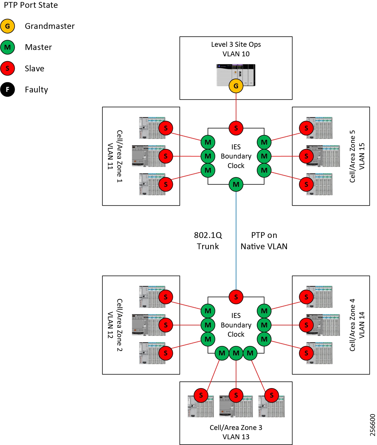
An 802.1q trunk connects the two IES. Trunks are used to allow multiple VLANs to pass across a single Ethernet link. The IES boundary clock can only send and receive PTP on a single VLAN on the trunk. By default, PTP is passed on the native VLAN of the trunk. The native VLAN is used to build the master/slave relationship between the two IES. Like the top IES, the bottom IES will synchronize its clock to its master. Moreover, the IACS devices in VLANs 12, 13, and 14 will synchronize their clocks to the boundary clock in the lower IES.
This method allows all IACS devices in a multi-VLAN environment to synchronize their clocks to a single grandmaster clock and have a common time reference for all Cell/Area Zones in the plant-wide IACS architecture.
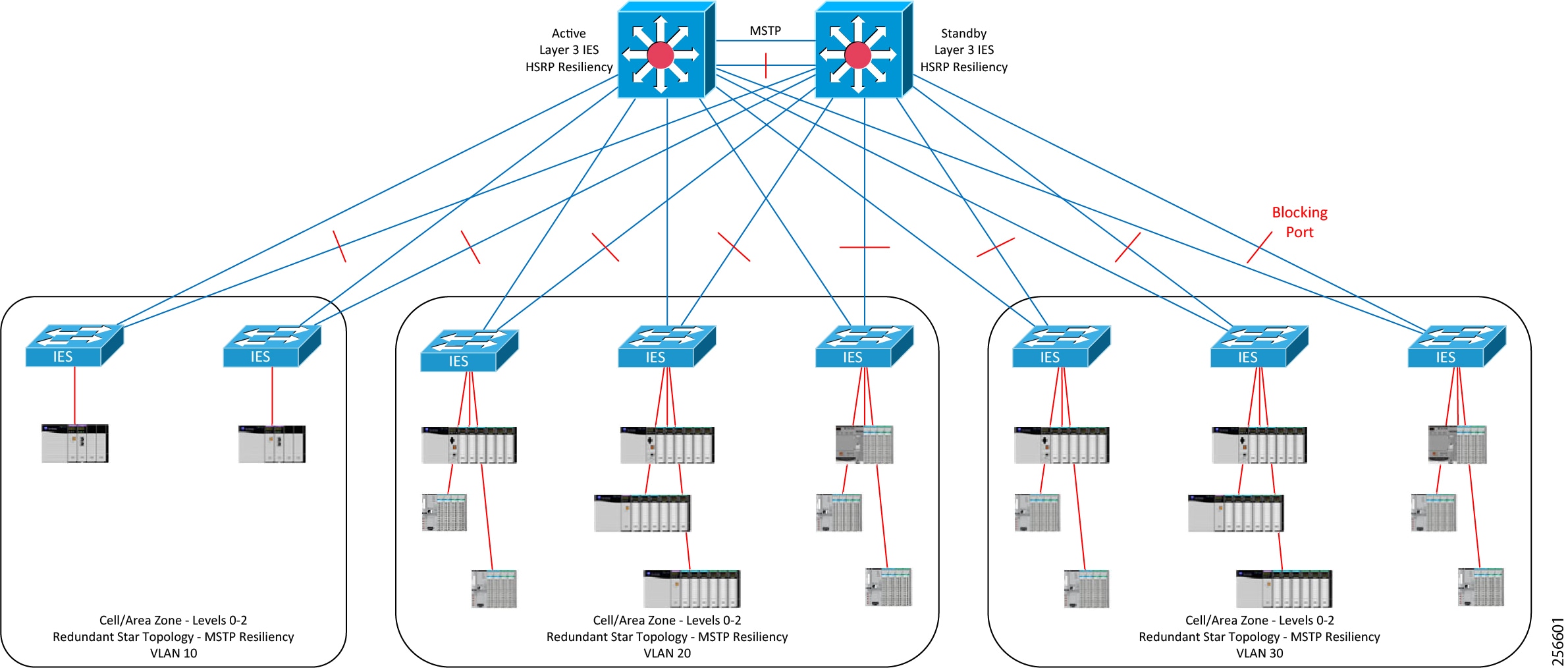
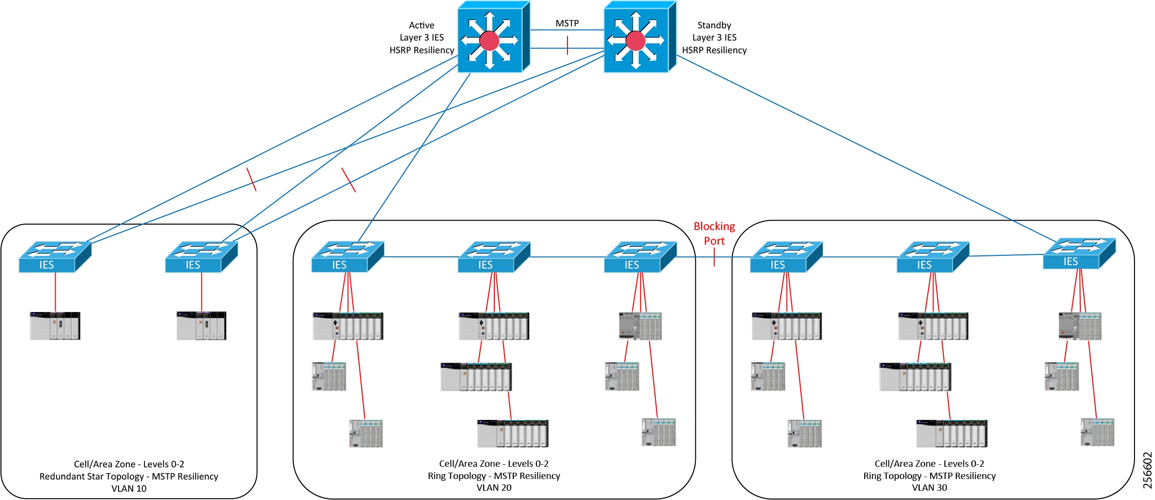
Reference Architecture 1—Redundant Star Topology
This architecture is based on the Allen-Bradley Stratix 5410 IES. It is configured with HSRP active/standby, and a Redundant Star Topology which includes the MSTP resiliency protocol. This is published in the Deploying a Resilient Plantwide Ethernet Architecture (CPwE Resiliency) Design and Implementation Guide. The CPwE Time solution differs in how the two distribution switches are connected together. The traditional redundant star topology features an EtherChannel to provide bandwidth and resiliency between the two distribution switches. This architecture replaces the EtherChannel with two 10 Gigabit Ethernet links running MSTP. Network convergence testing was not performed on this architecture and the convergence times may be higher than what is published in the CPwE Resiliency DIG.
Note![]() The Allen-Bradley Stratix IES and Cisco Catalyst switches do not support PTP over EtherChannels.
The Allen-Bradley Stratix IES and Cisco Catalyst switches do not support PTP over EtherChannels.
Figure 2-4 MSTP Redundant Star Topology
Reference Architecture 2—Ring Topology
The CPwE Time solution also supports MSTP ring topologies using the modified distribution switch architecture as decribed in Reference Architecture 1—Redundant Star Topology. As with the redundant star topology, MSTP was used for the resiliency protocol and was not tested for topology convergence performance. It is important to note that ring topologies cascade boundary clocks and will likely reduce clock accuracy in the IACS application. In the CPwE Time solution, rings were only tested with six IES plus the two IES distribution switches.
PTP and MSTP Topologies Overview
In most cases, the loss of the active uplink from an access switch to the distribution will introduce both a Layer 2 MSTP topology change and a PTP topology change. It is important to manage how the PTP topology converges to limit the impact on time synchronization within the Cell/Area Zone.
The following sections describe what happens to PTP and MSTP topologies during normal steady state operation and the convergence event.
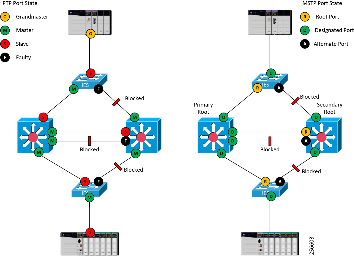
PTP and MSTP Topologies (Steady State)
Figure 2-6 shows a simple topology using two IACS devices: two access switches and two distribution switches. The access and distribution switches are all configured for boundary clock mode. In addition, the IACS device at the top of Figure 2-6 is the IACS application grandmaster. The drawing on the left shows the PTP topology with a cascading series of master and slave ports down to the IACS device at the bottom. The drawing on the right shows the same topology from a MSTP perspective. It is important to note that the MSTP alternate root ports are in the “faulty” PTP port state.
Figure 2-6 PTP and MSTP Topologies during Steady State
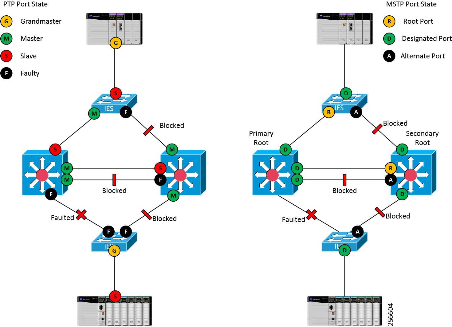
PTP and MSTP Topologies (Convergence Event)
In Figure 2-7, the link between the lower IES and the primary root bridge has faulted. This results in a condition where both uplinks from the lower IES are in the PTP fault state. This triggers a BMCA election within the Cell/Area Zone. One of the goals of this architecture is to manage this election to reduce the impact of the PTP topology change on IACS devices in the Cell/Area Zone. This is accomplished by weighting the BMCA so the IES in the Cell/Area Zone becomes the new grandmaster within the local Cell/Area Zone.
Figure 2-7 PTP and MSTP Topologies during Convergence
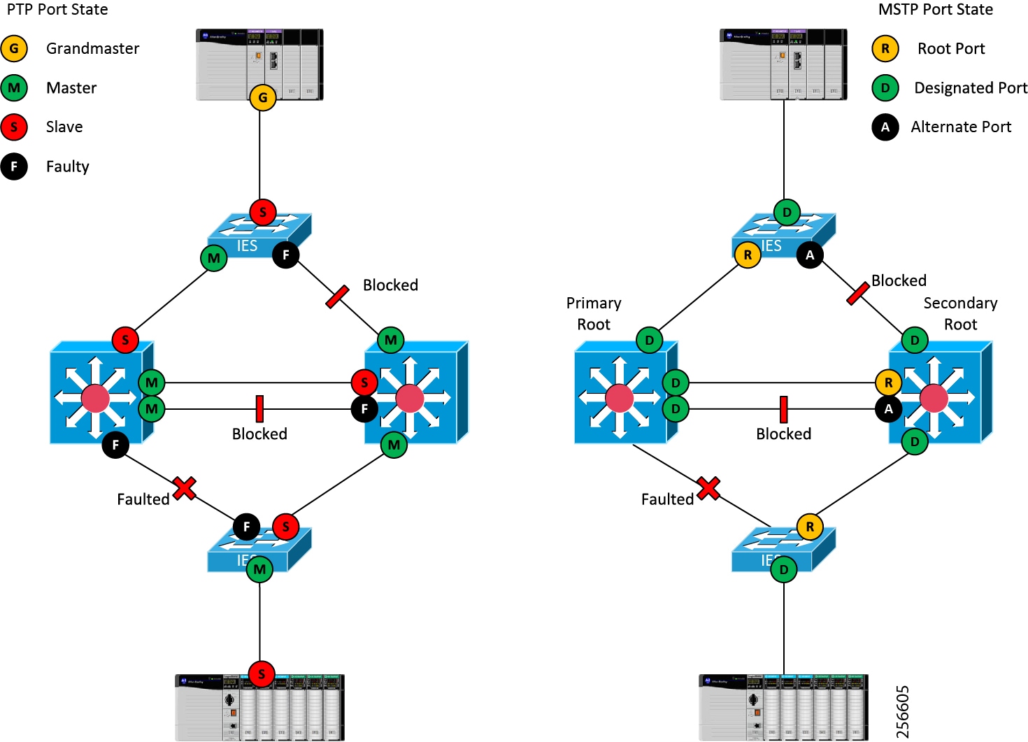
In Figure 2-8 MSTP has converged and the alternate root on the lower IES has become the new root port. This reestablishes a path to the IACS application grandmaster at the top of the topology. A BMCA election is triggered and the PTP topology is restored to its original state.
The crux of the CPwE Time solution is to use the boundary clock in the Cell/Area Zone IES to ride through the topology change. The Cell/Area Zone IES is configured to become the new grandmaster during the PTP convergence and is also configured to maintain the IACS application grandmaster PTP time properties such as the PTP timescale and the UTC offset during the Layer 2 topology change.
The solution weights the BMCA algorithm to better control the selection of the grandmaster both during normal operation and during a system fault. This architecture uses the PTP priority1 and priority2 values to divide the PTP topology into four tiers, each with its own role in maintaining time synchronization in the architecture.
Figure 2-8 PTP and MSTP Topologies after Convergence
Recommended PTP Clock Hierarchy and Configuration
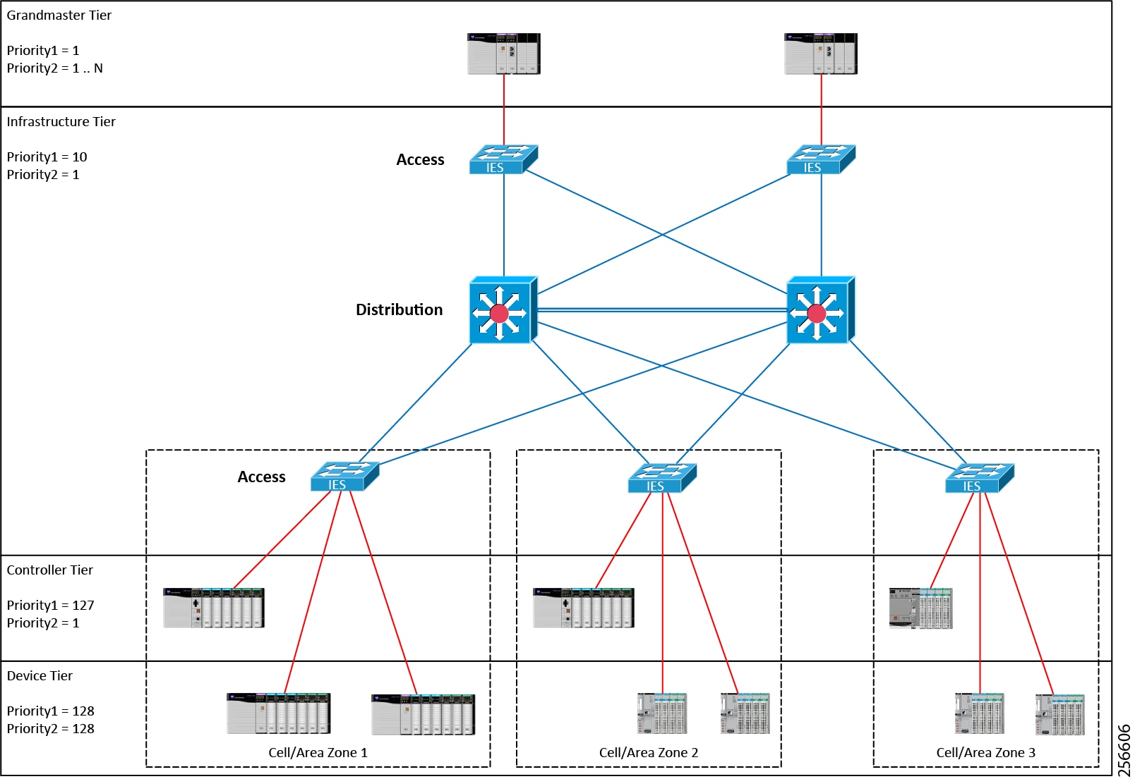
Figure 2-9 depicts recommended PTP clock hierarchy and configuration for both reference architectures shown in Figure 2-4 and Figure 2-5. It is designed to minimize the impact of Layer 2 topology changes on the PTP topology.
Figure 2-9 PTP Clock Hierarchy and Configuration
PTP Clock Hierarchy
This section describes the PTP clock hierarchy shown in Figure 2-9.
Grandmaster Tier
The grandmaster tier contains the designated grandmasters for the PTP domain. It is recommended to select an IACS device to be the primary grandmaster for the PTP domain. This device should have an accurate and reliable clock and ideally be synchronized to UTC using a reference clock. The primary grandmaster should be protected from faults such as power failures to improve stability of the PTP domain. It is also recommended to designate a secondary grandmaster which should use the same PTP timescale and UTC offset to minimize impact to the IACS application when the secondary grandmaster becomes the grandmaster. However, failing over from a primary grandmaster to a secondary grandmaster and vice versa may cause disruptions to time synchronization.
The IACS devices in the grandmaster tier should have the priority1 value set low so that they win the BMCA election. The priority2 value should be used to differentiate between the primary and secondary grandmasters with the primary having the lowest priority2 value.
It is recommended to provide power protection to the IACS devices in the grandmaster tier since a grandmaster failure is a system-wide event.
Infrastructure Tier
The infrastructure tier consists of the IES that allows the IACS devices to synchronize to the grandmaster. This architecture supports both redundant star and ring topologies with multiple VLANs. However, ring topologies require multiple cascaded boundary clocks that may reduce the accuracy of IACS devices further away from the grandmaster. PTP relies on the underlying infrastructure to build the PTP clock hierarchy. Moreover, a disruption to the underlying Layer 2 topology will cause a disruption to the PTP clock hierarchy. This can cause the loss of synchronization between IACS devices within the local Cell/Area Zone.
The infrastructure tier is designed to reduce the impact of topology changes on clock synchronization in the Cell/Area Zone. This is accomplished by weighting the BMCA algorithm so that the IES becomes the grandmaster during the event. Furthermore, the IES is configured to maintain the time properties, such as timescale and UTC offset of the grandmaster, since changes to the PTP timescale can introduce disruptions in time synchronization.
The IES should be configured as boundary clocks using the feedforward transfer function. The IES should have the priority1 value set so they become grandmaster if the IACS devices in the grandmaster tier are unreachable. In addition, the ptp time-property persist infinite command should be applied to all IES boundary clocks. Finally, it is recommended to set the PTP sync fault limit to 10,000 on all PTP-enabled IES interfaces.
Note![]() Use caution when setting the sync limit below 50,000. This setting should only be used in IACS applications where the grandmaster has a very high-precision clock and where all the IES have hardware support for PTP enabled.
Use caution when setting the sync limit below 50,000. This setting should only be used in IACS applications where the grandmaster has a very high-precision clock and where all the IES have hardware support for PTP enabled.
It is recommended to provide power protection to the infrastructure tier to improve overall IACS application reliability. OT engineers should consider installing the IES in separate enclosures with dedicated DC power supplies and backup batteries. If the IES are installed in the control panel with the IACS hardware, the OT engineer should consider using a dedicated DC power supply for the IES. These power supplies should be on a separate power disconnect so power can be removed from the IACS hardware while maintaining the network. This approach can help limit the number of Layer 2 and PTP topology changes experienced by the IACS application and help the overall stability of time.
Controller Tier
The controller tier is designed to reduce time synchronization issues when the IES is down, such as when the control panel is powered on as IACS devices take different number of times to start up. Some IACS devices like Programmable Automation Controllers (PAC) feature battery backed real-time clocks and will continue to keep time when the power is disconnected. These IACS devices should have their priority1 value set so they become grandmaster until connectivity to the network is restored. This reduces the chance of a device without a real-time clock becoming grandmaster and setting an arbitrary time, like January 1 1970 00:00:00. Some IACS devices such as FactoryTalk Historian ME modules may fault if they detect an IACS application time that is significantly earlier than the time logged for existing data points.
Device Tier
The device tier contains all other PTP-aware IACS devices. Most of these IACS devices exclude battery backed real-time clocks and will revert to some known epoch on startup, such as January 1 1970 00:00:00. Therefore, they should not be relied on as a grandmaster clock. Their priority1 and priority2 values should be set so they will not become the grandmaster. The device tier is likely to contain most of the IACS devices in the plant-wide IACS architecture. The overhead of configuring the system can be reduced by using the default priority1 and priority2 value of 128 for the IACS devices in the device tier.
Recommended PTP Clock Configuration
In the PTP architecture shown in Figure 2-9, two 1756-TIME modules are used in the grandmaster tier. The 1756-TIME modules use GPS receivers to synchronize their clocks to UTC. The primary grandmaster has its priority1 set to 1 and its priority2 set to 1. The secondary grandmaster has its priority1 set to 1 and its priority2 set to 2.
A mix of Allen-Bradley Stratix 5700, 5400, and 5410 IES are used in the infrastructure tier. All IES in the infrastructure tier have their priority1 set to 10 and their prioirty2 set to 1.
The controller tier consists of a mix of ControlLogix® 5380, 5570, and 5580 PACs. The PACs have their priority1 value set to 127 and their priority2 value set to 1.
The remainder of the IACS devices in the IACS application consist of various I/O platforms and have their priority1 and priority2 values at the default of 128.
Summary of Recommendations
–![]() Select a specific device to be a reliable grandmaster for the IACS application.
Select a specific device to be a reliable grandmaster for the IACS application.
–![]() Protect the grandmaster from faults such as power disruptions to increase stability of the IACS application.
Protect the grandmaster from faults such as power disruptions to increase stability of the IACS application.
–![]() Synchronize the grandmaster to UTC.
Synchronize the grandmaster to UTC.
–![]() Use IES in boundary clock mode to propagate time between VLANs.
Use IES in boundary clock mode to propagate time between VLANs.
–![]() Use the feedforward transfer function and the sync limit to improve synchronization across the IACS application.
Use the feedforward transfer function and the sync limit to improve synchronization across the IACS application.
–![]() Use the time properties persist command to help ride through the loss of the grandmaster.
Use the time properties persist command to help ride through the loss of the grandmaster.
–![]() Isolate and provide battery backed power to the IES to reduce Layer 2 and PTP topology changes.
Isolate and provide battery backed power to the IES to reduce Layer 2 and PTP topology changes.
–![]() Use a redundant star topology to reduce time error in the IACS application.
Use a redundant star topology to reduce time error in the IACS application.
–![]() Do not send PTP traffic over EtherChannels.
Do not send PTP traffic over EtherChannels.
–![]() Configure IACS devices with real-time clocks, such as PACs, to become the grandmaster if the network is down.
Configure IACS devices with real-time clocks, such as PACs, to become the grandmaster if the network is down.
–![]() Use the default priority1 and 2 values to simplify configuration.
Use the default priority1 and 2 values to simplify configuration.
 Feedback