- SCADA Control Center Point-to-Point Implementation Scenarios Over Cellular Gateways
- SCADA Communication with IP Intelligent Devices
- SCADA Communication Scenarios over CR Mesh Network (IEEE 802.15.4)
- SCADA Communication with Serial-based SCADA using Raw Socket UDP
- SCADA Communication with Serial-based SCADA using Raw Socket TCP
- Legacy SCADA (Raw Socket TCP Server)
Distribution Automation - Feeder Automation Implementation Guide
This Cisco Distribution Automation- Feeder Automation Implementation Guide provides a comprehensive explanation of the Cisco Smart Grid Field Area Network solution implementation for Distribution Automation use cases such as Fault Location, Isolation, and Service Restoration (FLISR) and Volt/VAR. This implementation document includes information about the solution architecture, possible deployment models, and guidelines for deployment. It also recommends best practices and potential issues when deploying the reference architecture.
Navigator
The document covers the following:
Audience
The audience for this guide comprises, but is not limited to, system architects, network/compute/systems engineers, field consultants, Cisco Advanced Services specialists, and customers. Readers should be familiar with networking protocols, Network Address Translation (NAT), Supervisory Control and Data Acquisition (SCADA) protocols, and be exposed to Field Area Networks.
New Capabilities in DA2.0 Feeder Automation
■![]() Implementation details of the FLISR (Fault Location Isolation and Service Restoration) use cases.
Implementation details of the FLISR (Fault Location Isolation and Service Restoration) use cases.
■![]() Simulation details of the FLISR (Fault Location Isolation and Service Restoration) use cases, using SEL application AcSELerator.
Simulation details of the FLISR (Fault Location Isolation and Service Restoration) use cases, using SEL application AcSELerator.
Introduction
The Cisco Field Area Network solution is a multi-service, secured, and scalable architecture, which addresses multiple utility use cases like Distribution Automation (DA), Advance Metering Infrastructure (AMI), Distributed Energy Resource (DER), and Demand Response (DR). This document details the implementation of FAN Distribution Automation, FLISR, and Volt/VAR use cases targeting deployment in the America region.
The implementation in this guide focuses on Distributed Network Protocol 3 (DNP3) and DNP3/IP SCADA protocols. For implementing Distribution Automation use cases using T101 or T104 SCADA protocols, please refer to the Distribution Automation - Feeder Automation Implementation Guide at the following URL:
■![]() https://salesconnect.cisco.com/open.html?c=06d2f8be-8c59-4d3d-9659-0d780c3da744
https://salesconnect.cisco.com/open.html?c=06d2f8be-8c59-4d3d-9659-0d780c3da744
The Cisco FAN solution is a centralized two-tier architecture, as shown in Figure 1. Distribution Automation applications like Distribution Management System and Outage Management System reside in the Distribution System Operator (DSO) control center.
Cisco’s Distribution Automation Gateways interface with Distribution Automation control devices like Capacitor Bank Controllers (CBCs) and recloser controllers that reside on the distribution feeder (in some cases, inside distribution substations like the Load Tap Controller). This interfacing could be either the Ethernet or Serial type.
Cisco’s Distribution Automation Gateways could transport their traffic over a Cellular backhaul or Ethernet backhaul, or via the Neighbor Area Network (NAN) formed by Cisco Resilient Mesh Gateways. Cisco Gateways, which have one leg in the NAN tier and the other in the WAN tier, aggregate the distribution traffic from the NAN tier and route traffic to various DA applications via the WAN tier (which could be a Cellular or Fiber backhaul connection). To choose the correct DA Gateway, please refer to the Distribution Automation - Feeder Automation Design Guide at the following URL:
■![]() https://www.cisco.com/c/dam/en/us/td/docs/solutions/Verticals/Distributed-Automation/Feeder-Automation/DG/DA-FA-DG.pdf
https://www.cisco.com/c/dam/en/us/td/docs/solutions/Verticals/Distributed-Automation/Feeder-Automation/DG/DA-FA-DG.pdf
This implementation guide covers both Cisco Cellular Gateway and Cisco Resilient Mesh Gateway deployments.
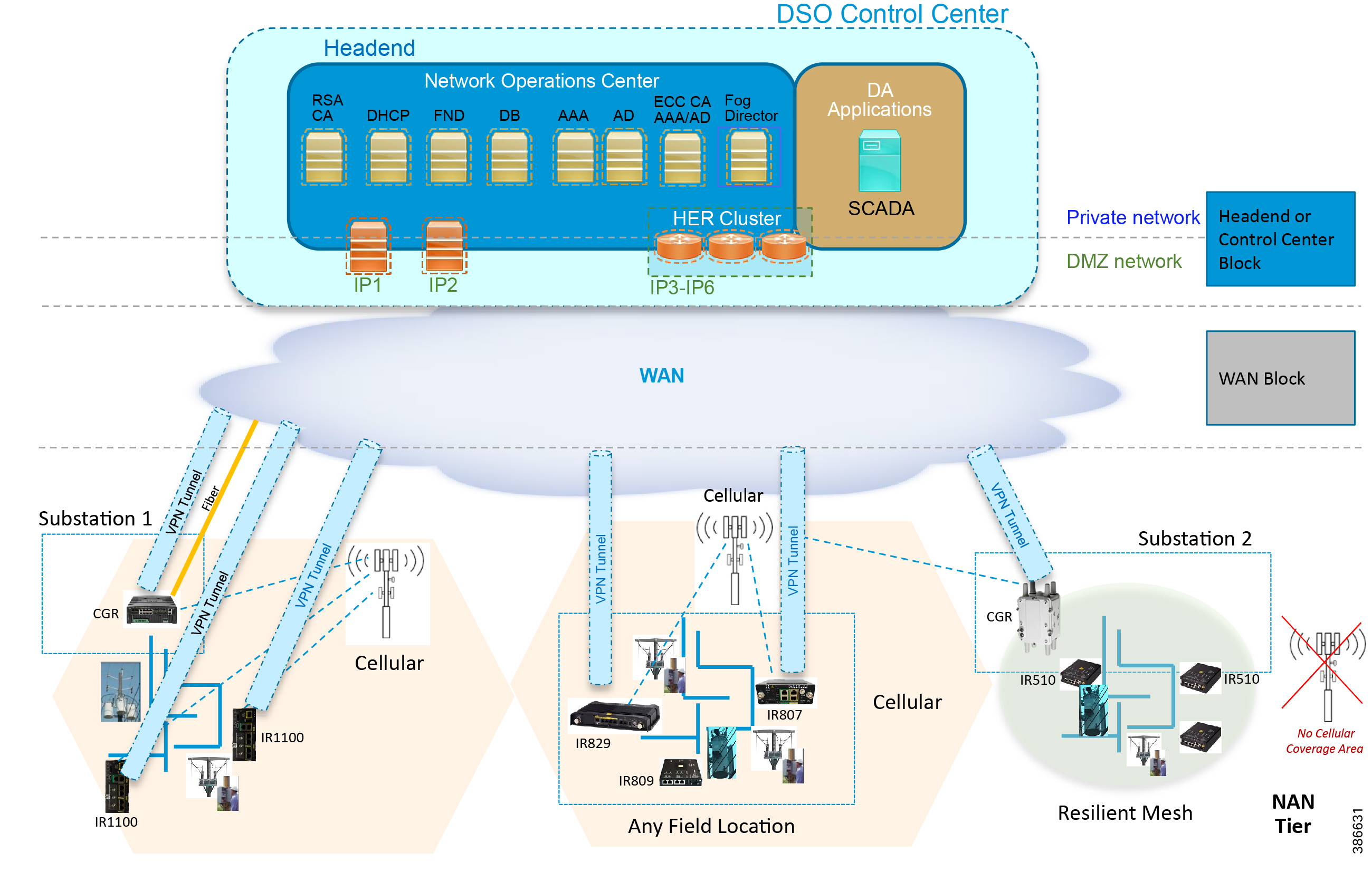
Cisco Resilient (CR) Mesh implementation will be the correct choice for areas where Cellular coverage is not available or less prevalent. Cisco CR mesh has three types of devices:
■![]() CR Mesh Co-ordination or Field Area Aggregation Router (FAR)
CR Mesh Co-ordination or Field Area Aggregation Router (FAR)
■![]() CR Mesh Gateways or Field Devices (FD)
CR Mesh Gateways or Field Devices (FD)
Cisco CGR 1240 with WPAN RF Module router plays the role of CR Mesh aggregator. CGR 1240 aggregates DA traffic and routes traffic to applications in the DSO control center. Distribution Automation controllers are connected to CR Mesh Gateways like IR510 via Ethernet or Serial (RS232) interfaces. When RF mesh coverage needs to be extended, Cisco IR530 could be deployed as range extenders. The CR Mesh is formed using FAR, FD, and range extenders and can be implemented in multiple PHY modes. This implementation guide is focused on DA use cases and requires relatively larger bandwidth when compared to the AMI use case; therefore, OFDM modulation with 800 Kbps profile has been chosen. This implementation covers Fixed OFDM 800 Kbps modulation. Adaptive Rate modulation, although supported, is not covered in this guide.
Cisco Cellular DA Gateways like IR1101, IR807, IR809, and CGR 1120 can be chosen for deployments where:
■![]() DA Application demands more bandwidth and has time sensitive requirements.
DA Application demands more bandwidth and has time sensitive requirements.
■![]() Distribution Feeder has better Cellular signal coverage (for example, urban areas).
Distribution Feeder has better Cellular signal coverage (for example, urban areas).
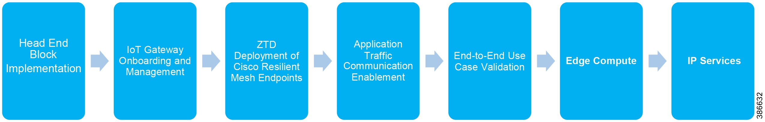
The flow of this implementation guide is depicted in Figure 2.
Note: For Headend Block Implementation, please refer to the Cisco FAN - Headend Deep Dive Implementation and FAN Use Cases at the following URL:
■![]() https://salesconnect.cisco.com/open.html?c=da249429-ec79-49fc-9471-0ec859e83872
https://salesconnect.cisco.com/open.html?c=da249429-ec79-49fc-9471-0ec859e83872
Solution Network Topology and Addressing
This chapter, which focuses on the network topology used for solution validation and implementation of the Cisco DA Feeder Automation solution and the addressing (both IPv4 and IPv6) used in this implementation, includes the following major topics:
Topology Diagram
This section describes the high-level solution validation topology that has been used in this Feeder Automation Implementation Guide. Figure 3 depicts the high-level solution validation topology.
Figure 3 Cisco DA Feeder Automation Solution Validation Topology
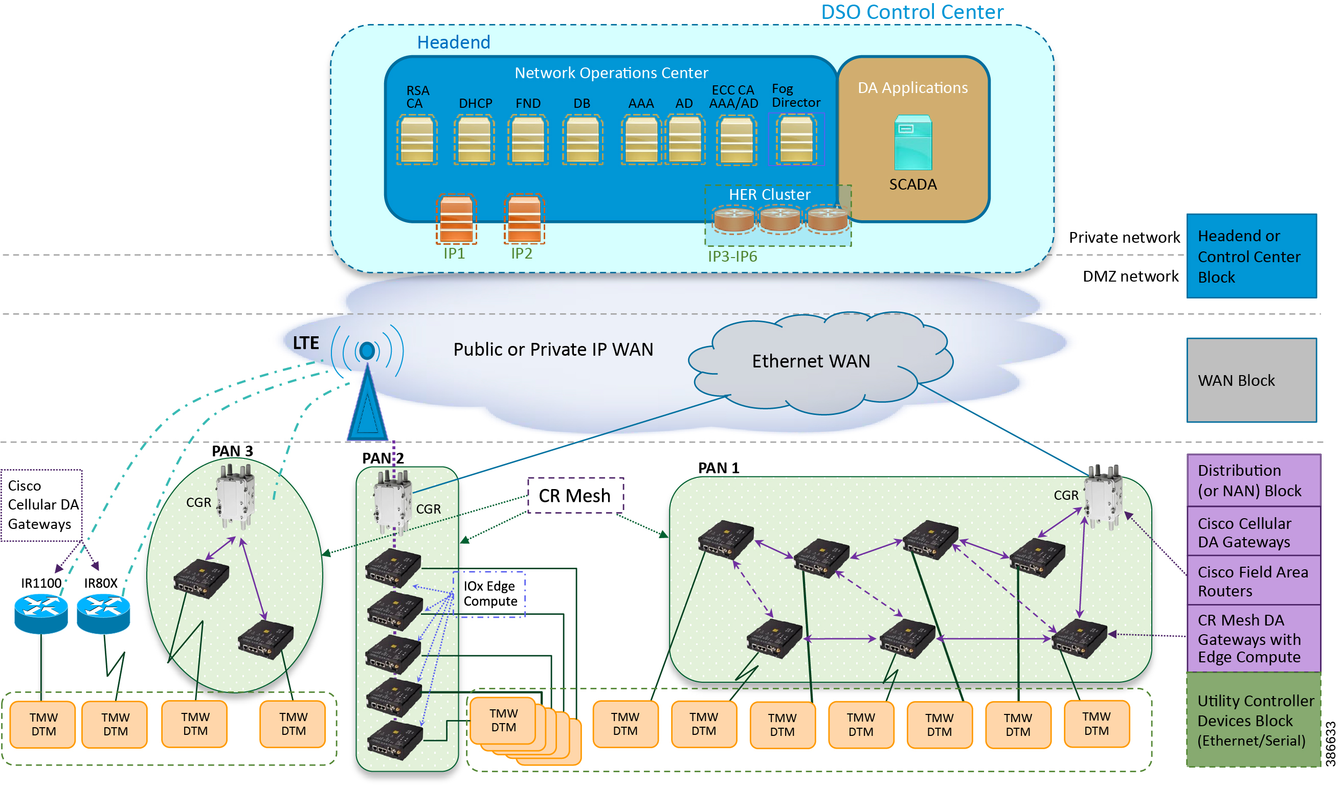
The multiple layers of topology include:
■![]() The Headend or Control Center Block, which hosts the DSO Control Center, includes:
The Headend or Control Center Block, which hosts the DSO Control Center, includes:
–![]() DA application servers (for example, SCADA application server):
DA application servers (for example, SCADA application server):
–![]() Network Operations Center (NOC), which hosts the following headend components:
Network Operations Center (NOC), which hosts the following headend components:
- Certificate Authority (RSA encryption), Dynamic Host Configuration Protocol (DHCP), Field Network Director (FND), FND Database, Authentication Authorization and Accounting (AAA), Active Directory (AD), Certificate Authority (ECC encryption), Fog Director (FD), Registration Authority (RA), Tunnel Provisioning Server (TPS), and Cluster of Headend Routers.
- These components are essential for the ZTD of the Cisco IOS Routers, which could be DA Gateways (IR1101, IR807, IR800) that are positioned along the Distribution Feeder or CGR1000 series of routers positioned as FARs.
–![]() Headend block, which includes:
Headend block, which includes:
- Private network, where the protected part of the headend is located, along with SCADA and other application servers.
- DMZ network, where the exposed part of the headend is located; it includes TPS, RA, and HER Cluster.
■![]() The WAN Block commonly refers to the public Internet over Ethernet/cellular backhaul. It could also be a private IP network.
The WAN Block commonly refers to the public Internet over Ethernet/cellular backhaul. It could also be a private IP network.
■![]() The Distribution Block, which comprises the following three major sub-blocks:
The Distribution Block, which comprises the following three major sub-blocks:
–![]() Cisco Cellular DA Gateways, which refer to Cisco IOS Routers like IR1100, IR807, and IR809.
Cisco Cellular DA Gateways, which refer to Cisco IOS Routers like IR1100, IR807, and IR809.
–![]() Cisco Field Area Routers, which refer to Cisco IOS Routers like CGR1240 and CGR1120. These routers are used for aggregating the Cisco Resilient Mesh Endpoints (also referred as CR Mesh DA Gateways). The NAN Block is a subset of the Distribution Block, comprising CR Mesh devices, including Cisco FAR and CR Mesh endpoints.
Cisco Field Area Routers, which refer to Cisco IOS Routers like CGR1240 and CGR1120. These routers are used for aggregating the Cisco Resilient Mesh Endpoints (also referred as CR Mesh DA Gateways). The NAN Block is a subset of the Distribution Block, comprising CR Mesh devices, including Cisco FAR and CR Mesh endpoints.
–![]() Cisco Resilient (CR) Mesh DA Gateways with Edge Compute, which refer to the Cisco IR510 WPAN Industrial Router.
Cisco Resilient (CR) Mesh DA Gateways with Edge Compute, which refer to the Cisco IR510 WPAN Industrial Router.
■![]() The Utility Controller Devices Block, in which the Utility controller devices (real/simulated) are connected to the Cisco DA Gateways (Cellular DA Gateway or Mesh DA Gateway) over an Ethernet/Serial interface. The following components are simulated using the Triangle Micro Works (Distributed Test Manager or DTM) tool:
The Utility Controller Devices Block, in which the Utility controller devices (real/simulated) are connected to the Cisco DA Gateways (Cellular DA Gateway or Mesh DA Gateway) over an Ethernet/Serial interface. The following components are simulated using the Triangle Micro Works (Distributed Test Manager or DTM) tool:
–![]() SCADA Master located in DSO Control Center
SCADA Master located in DSO Control Center
–![]() IEDs located in the Utility Controller Devices Block layer
IEDs located in the Utility Controller Devices Block layer
■![]() The NAN Block, which is comprised of three Personal Area Networks (PANs):
The NAN Block, which is comprised of three Personal Area Networks (PANs):
PAN3 has been validated over LTE backhaul. PAN1 and PAN2 have been validated over Ethernet backhaul. Cisco IOx Edge Compute functionality has been validated over PAN2. Fog Director (FD) located in the DSO control center has been used for the lifecycle management of Edge compute applications on the IOx platform of CR Mesh DA Gateway.
For implementation involving dual control scenarios, please refer to the Distribution Automation - Feeder Automation Implementation Guide.
IPv4 and IPv6 Addressing
This section, which provides detail about the addressing used at every layer of the Figure 1 Cisco DA Feeder Automation solution validation topology, includes the following sections:
■![]() Addressing in the DSO Control Center Block
Addressing in the DSO Control Center Block
Addressing in the DSO Control Center Block
Figure 4 captures the granular details of the DSO Control Center.
Figure 4 DSO Control Center Block—Zoom In
The DSO Control Center is comprised of two types of network: the Private Network and the DMZ Network
■![]() The Private Network hosts an UCS server (with all the required head end components like FND, Certificate Authority, DHCP server, and so on), SCADA Master as well as Fog Director. Private Network leverages the Cisco NTP for time synchronization, as well as Cisco DNS servers for name resolution.
The Private Network hosts an UCS server (with all the required head end components like FND, Certificate Authority, DHCP server, and so on), SCADA Master as well as Fog Director. Private Network leverages the Cisco NTP for time synchronization, as well as Cisco DNS servers for name resolution.
■![]() The DMZ Network hosts a cluster of Headend Routers (ASR 1000), TPS, and Registration Authority. These components connect to the DMZ Network on one side and the Private Network on the other side.
The DMZ Network hosts a cluster of Headend Routers (ASR 1000), TPS, and Registration Authority. These components connect to the DMZ Network on one side and the Private Network on the other side.
For more details about implementing the headend in the DSO Control Center, please refer to the Cisco FAN-Headend Deep Dive Implementation and FAN Use Cases Guide.
Addressing in the Private Network
Table 1 captures the addressing details of the components located in the private network of DSO Control Center.
Addressing in the DMZ Network
The previous topology in Figure 4 shows that components that are located in the DMZ Network (reachable over WAN) include the following:
■![]() Tunnel Provisioning Server (TPS)
Tunnel Provisioning Server (TPS)
■![]() HER Cluster of ASR 1000 series of routers
HER Cluster of ASR 1000 series of routers
Table 2 captures the addressing details of the components located in the DMZ network of DSO Control Center.
Note: The Virtual IP for FAN-PHE-HER1, FAN-PHE-HER2, and FAN-PHE-HER3 is 10.10.100.100.
Addressing in the WAN Block
The Public IP WAN has been validated in this implementation guide. Addressing in the WAN block is typically service provider managed. As long as the Cisco FARs or Cisco Cellular IoT Gateways in the Distribution Block receive a dynamically-assigned IP address from the service provider and are able to reach the components in the DMZ network, the requirement would be met.
Addressing in the Distribution Block
Addressing in the Distribution blocks is discussed granularly in the following sections:
■![]() Addressing used in Cisco Cellular DA Gateways
Addressing used in Cisco Cellular DA Gateways
Addressing used in Cisco Cellular DA Gateways
Figure 5 captures the various interfaces on the Cisco Cellular DA Gateways that are involved in the solution.
Figure 5 Addressing used in Cisco Cellular DA Gateways 256396
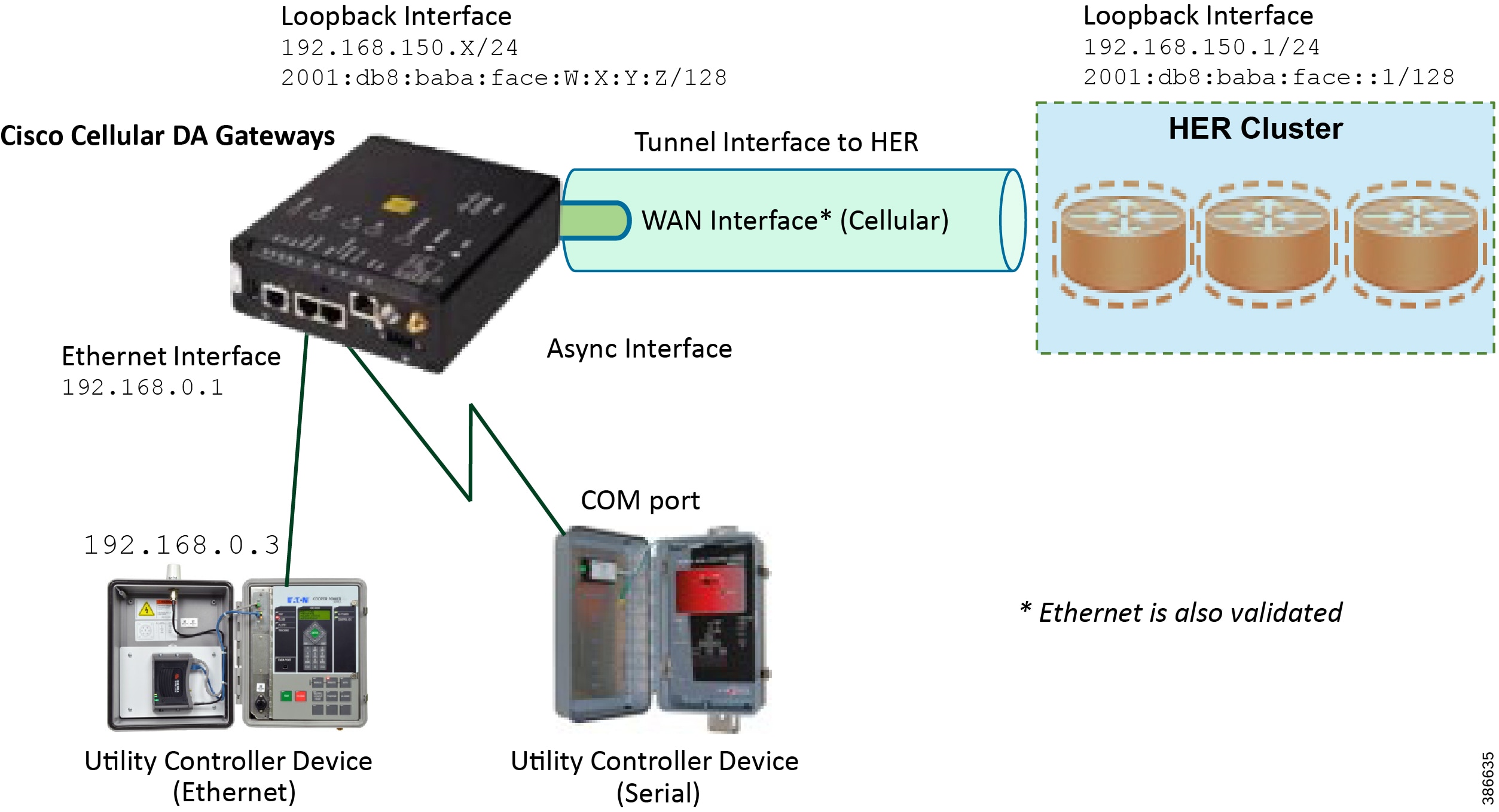
Table 3 captures the addressing used in Cisco Cellular DA Gateways.
Note: Some Cisco FAR devices available are CGR1120, CGR1240, IR1101 and IR807.
Addressing used in Cisco Field Area Routers
Figure 6 captures the various interfaces on the Cisco FARs that are involved in the solution.
Figure 6 Addressing used in Cisco Field Area Routers
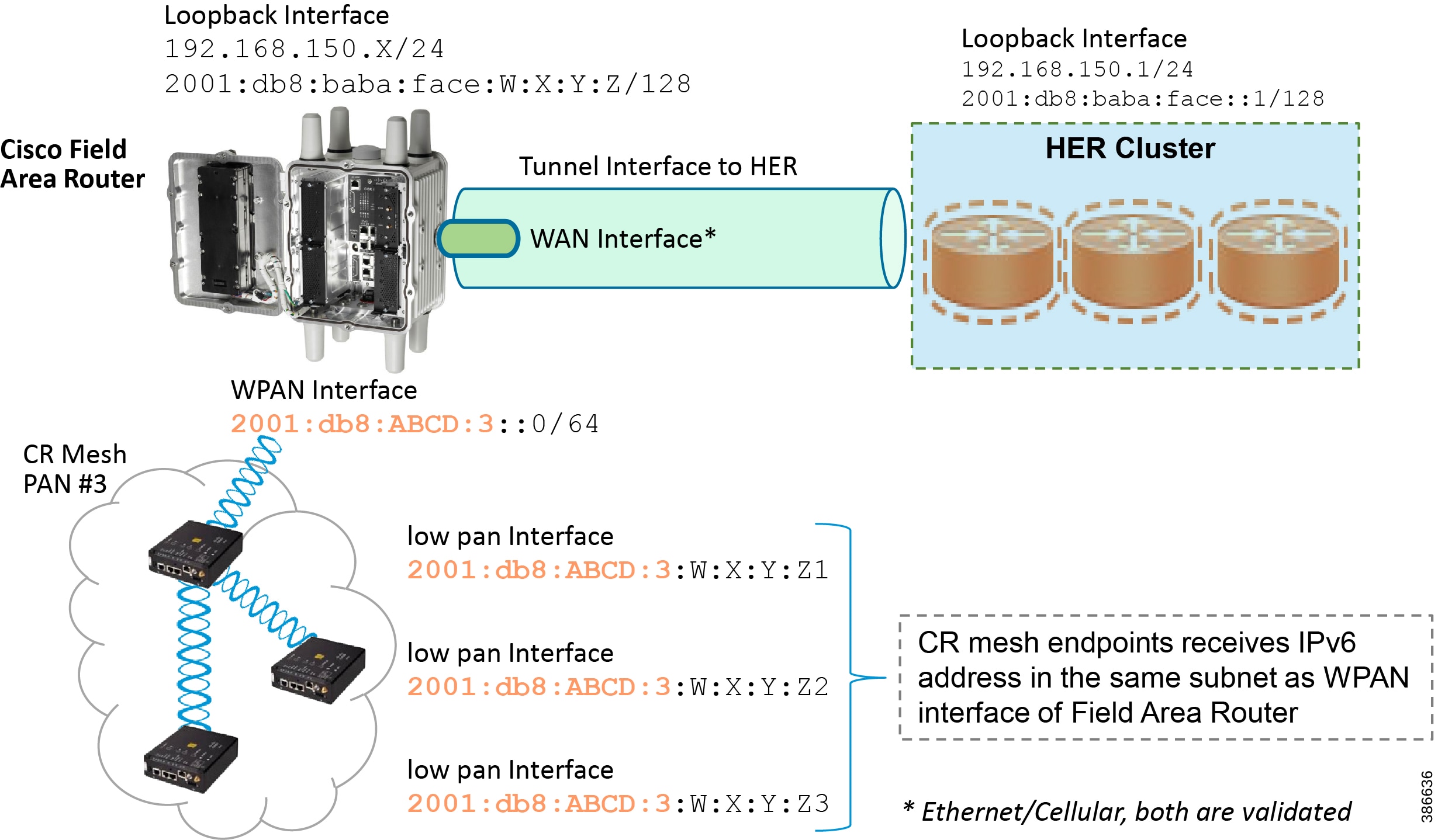
Table 4 captures the various interfaces used in the Cisco FAR and its associated addressing.
Addressing used in Cisco Resilient Mesh DA Gateways
Figure 7 captures the various interfaces on the Cisco Resilient Mesh DA Gateways that are used in this solution.
Figure 7 Addressing used in Cisco Resilient Mesh DA Gateways
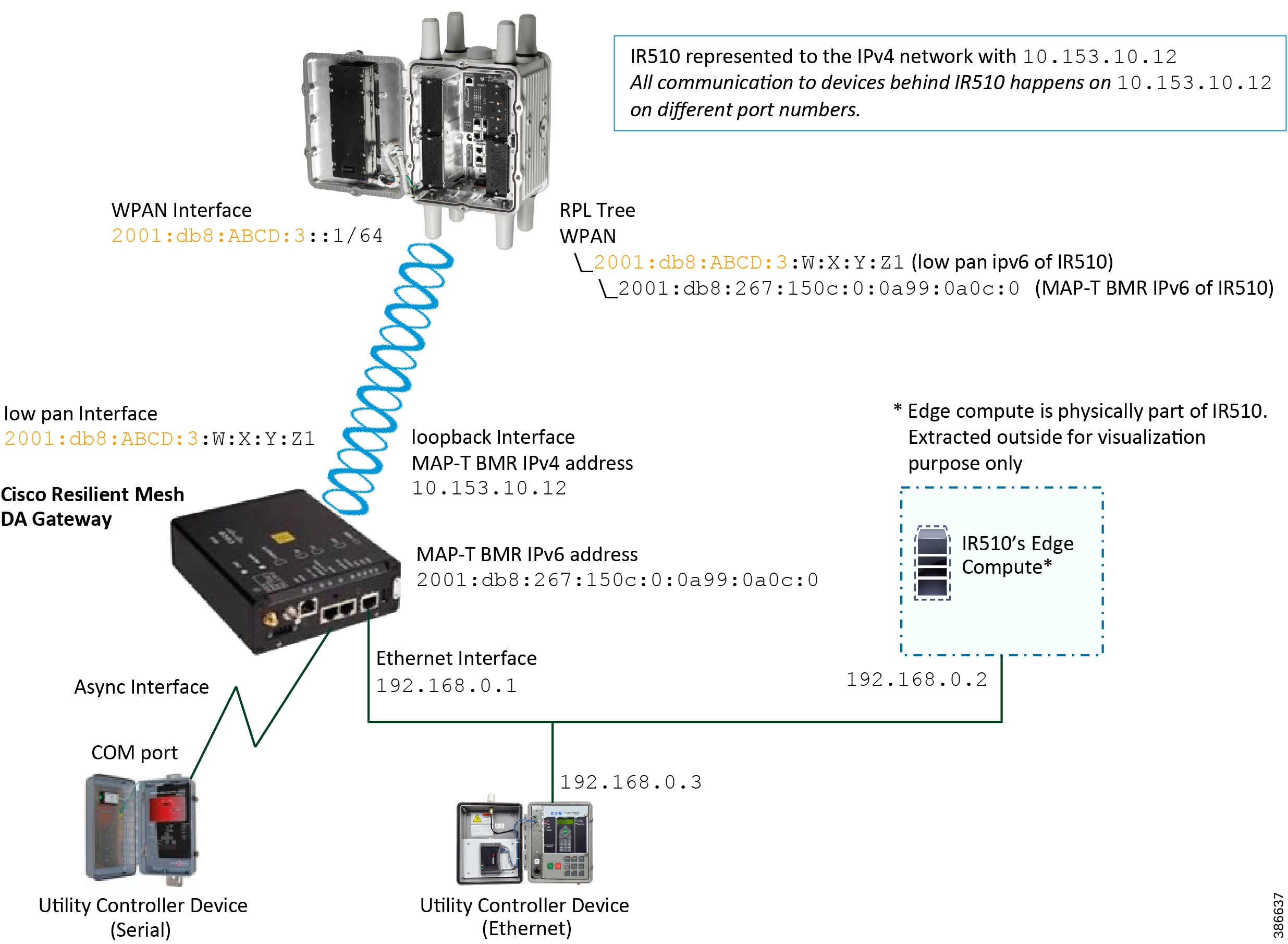
IR510 receives the IPv6 address for the LoWPAN interface from CGR. The IPv6 address of IR510 LoWPAN interface and the CGR WPAN interface are on the same IPv6 subnet. The CGR would serve as the default gateway for IR510.
Table 5 captures the various interfaces used in the CR Mesh DA Gateway and its associated addressing.
Addressing in the Utility Controller Devices Block
The Ethernet-based Utility Controller devices is to be configured with 192.168.0.3. It can be connected to the Ethernet ports of the Cisco Cellular DA Gateway or the CR Mesh DA Gateway. In this implementation, controller devices were simulated using Triangle Micro Works (Distributed Test Manager) tool. This simulated controller device is configured with 192.168.0.3 during this validation.
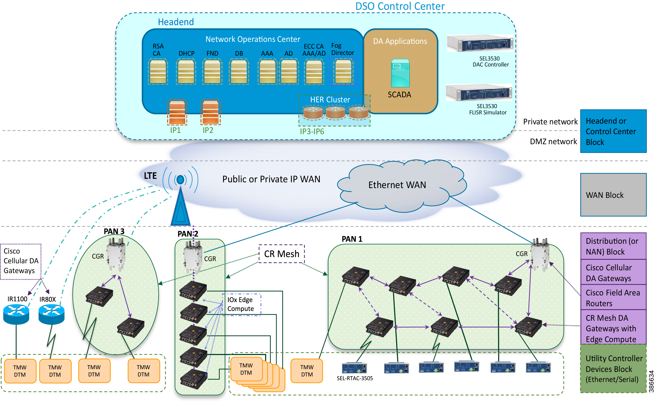
Solution Network Topology and Addressing for FLISR validation
This chapter, which focuses on the network topology used for solution validation and implementation of the Cisco DA 2.0 FLISR solution and the addressing (both IPv4 and IPv6) used in this implementation, includes the following major topics:
■![]() Topology Diagram for FLISR, page 5
Topology Diagram for FLISR, page 5
■![]() IPv4 and IPv6 Addressing, page6
IPv4 and IPv6 Addressing, page6
SEL FLISR solution is validated over Cisco Resilient Mesh on two different topologies. One is linear CR mesh with depth of 10 hops, which is typical rural deployment scenario and the second topology is aggregate CR mesh with depth of four rank nodes and four nodes connected at each rank level, Aggregate mesh is typically used in urban deployment scenario. For more details of these two types of deployment scenario, refer to Distribution Automation 2.0 – Feeder Automation Design Guide document.
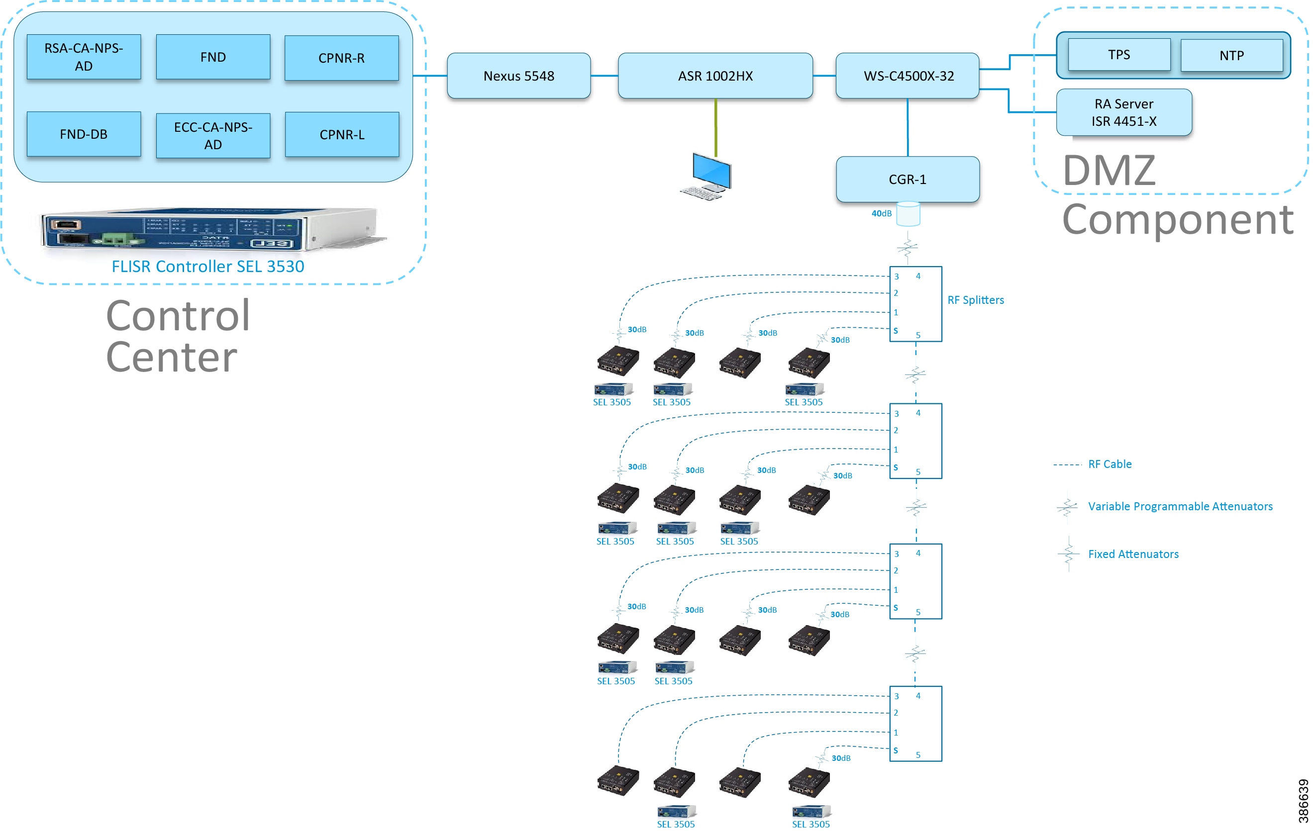
Topology Diagram for FLISR
This Linear and Aggregated Mesh topology constructed using RF coax cables, power splitters and attenuators, enabling signal variations to construct a 10-hop linear and 23 nodes aggregated mesh network. In mesh network nodes that can hear each other, in that the RSSI (Reverse Signal Strength Indication) is within the acceptable range for a specific modulation (OFDM) fixed modulation and data rate established between parent, child, and neighbor nodes.
The RF connectivity between the DA gateways designed for IEEE 802.15.4 Option 2 (OFDM fixed modulation PHY mode149 on Cisco Resilient Mesh) which corresponds to a physical layer data rate of 800kbps. The OFDM 800kbps maximum Receive Signal Strength Indicator (RSSI) is -101db. To avoid node flapping and instability in the network a new node joining the mesh network for the first time must have minimum RSSI of -91db with respect to its neighbor. So, for a best practice design rule that the link between DA devices is designed the average link RSSI range between -70db to -90db.
The mesh radio parameter configured using IEEE 802.15.4g and Routing Protocol for Low Power and Lossy Networks (RPL) timers. Mesh is also configured to operate in Storing Mode to support peer to peer communication.
This section describes the solution validation topology that has been used in this DA 2.0 FLISR Implementation Guide.
Linear Mesh lab topology for FLISR
In linear topology each node has two neighbors, one parent from upper rank close to CGR and one child from lower rank. The RSSI also designed for same RSSI range as showing in the topology. On lower ranks, as the hop counts increase, the latency values also increase due to each node adds its own processing delays. So the end to end, i.e. each hop to control center path delay will be longer.
Figure 8 depicts the DA 2.0 Linear Mesh Lab Topology.
Figure 8 Linear Mesh lab topology diagram
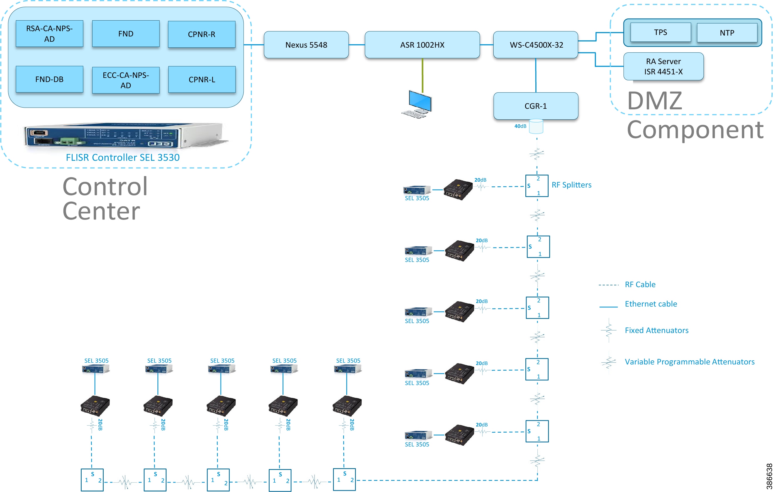
In the linear topology, fixed and variable attenuators are added to achieve an RSSI range of -70 to -90dB. RF Splitters are added at appropriate RF links, as shown in above lab topology figure, for creating a linear CR mesh.
Each SEL-3505 RTAC is connected to each IR510 device via Ethernet connection. SEL-3530 RTAC, which act as a SCADA Master and DAC Controller is located in Control Center.
Refer to Addressing in the DSO Control Center Block section for the Control Center details.
Aggregated Mesh lab topology for FLISR
In aggregate topology the distance between DA Grid device is shorter and nodes can aggregate traffic from multiple children. The ratio of child to parent is higher and the parent available bandwidth is shared among the children. To simulate this network the 2nd, 3rd, and 4th rank nodes were designed to establish physical layer 1 connection with first node of parent rank. The aggregation topology can be designed in multiple way to select their parent, limitations are applied due to lab environment and worst conditions. Refer to the topology for this implementation.
Note: This implementation is purely based on the topology provided in this section.
Figure 9 depicts the DA 2.0 Aggregated Mesh Lab Topology.
Figure 9 Aggregate Mesh lab topology diagram
In the aggregate topology, fixed and variable attenuators are added to achieve an RSSI range of -70 to -90dB. RF Splitters are added at appropriate RF links, as shown in above lab topology figure, for creating a linear CR mesh.
Each SEL-3505 RTAC is connected to each IR510 device via ethernet connection. SEL-3530 RTAC, which act as a SCADA Master and DAC Controller is located in Control Center.
Refer to DSO Control Center Block section for the Control Center details.
IPv4 and IPv6 Addressing
For general and complete IPv4 and IPv6 addressing please refer to the “Solution Network Topology and Addressing” section in this document. The specific FLISR configurations are shown below.
Table 6 Additional components for Field Block for FLISR
|
|
|
|
|---|---|---|
|
|
|
|
CGR 1240 Configuration
Please refer to Zero Touch Enrollment of Cisco Resilient Mesh Endpoints for IR510 device.
IoT Gateway Onboarding and Management
This chapter includes the following major topics:
■![]() Tunnel Provisioning Server/Field Network Director Categories
Tunnel Provisioning Server/Field Network Director Categories
■![]() Bootstrapping the IoT Gateway
Bootstrapping the IoT Gateway
■![]() Deployment of the Cisco IoT Gateway
Deployment of the Cisco IoT Gateway
FND is used as the NMS in this solution. In this implementation guide, the terminology “IoT Gateway” is used to refer to both Cisco Cellular DA Gateways and Cisco FARs.
IoT Gateway Onboarding has been made very simple by following the steps below:
1.![]() Unpack the box containing the new IoT Gateway.
Unpack the box containing the new IoT Gateway.
2.![]() Use plug-and-play (PnP) infrastructure to bootstrap.
Use plug-and-play (PnP) infrastructure to bootstrap.
3.![]() After bootstrapping, power off the IoT Gateway and deploy at the desired location.
After bootstrapping, power off the IoT Gateway and deploy at the desired location.
4.![]() Power on the IoT Gateway for Zero Touch Deployment (ZTD).
Power on the IoT Gateway for Zero Touch Deployment (ZTD).
5.![]() The device is fully operational.
The device is fully operational.
As part of IoT Gateway onboarding with ZTD, the IoT Gateways are registered with the FND. From that point on, the FND located in the Control Center is used to remotely monitor/manage/troubleshoot the IoT Gateways, which are spread across the entire Distribution Automation network. This process has three phases:
3.![]() Remote Monitor/Manage/Troubleshoot the IoT Gateway.
Remote Monitor/Manage/Troubleshoot the IoT Gateway.
The two different approaches to bootstrapping and deployment of the IoT Gateway are:
■![]() Approach 1—IoT Gateway bootstrapped in staging location, deployed in a different location
Approach 1—IoT Gateway bootstrapped in staging location, deployed in a different location
■![]() Approach 2—IoT Gateway bootstrapped in deployment location
Approach 2—IoT Gateway bootstrapped in deployment location
Both approaches are now supported by Cisco IoT Gateways and this guide.
With Approach 1, bootstrapping of the IoT Gateways is done at the dedicated staging location. Once the devices are bootstrapped successfully, they are powered off and transported to the final deployment locations, where the devices are deployed and powered on.
With Approach 2, bootstrapping of the IOT Gateways is done at the deployment location. Once the devices are bootstrapped successfully, the ZTD process begins and no manual intervention is required.
Tunnel Provisioning Server/Field Network Director Categories
Bootstrapping TPS/FND
The TPS/FND located in the staging/bootstrapping environment that helps with PnP bootstrapping of the IoT Gateways are referred to as the bootstrapping TPS and bootstrapping FND.
Network Operating Center
The TPS/FND located in the NOC/Control Center environment that helps with ZTD of IoT Gateways is referred to as the NOC or Control Center TPS/FND. This TPS/FND located in the DSO Control Center helps with management of the IoT Gateways.
Note: The bootstrapping TPS/FND could be the same as or different from the NOC TPS/FND depending on the chosen approach.
Since Approach 1 is chosen for implementation in this guide, two different pairs of TPS/FND have been implemented:
For general implementation of TPS/FND, please refer to the detailed steps covered in the following sections of the Cisco FAN-Headend Deep Dive Implementation and FAN Use Cases Guide:
■![]() Implementing Tunnel Provisioning Server
Implementing Tunnel Provisioning Server
■![]() Implementing Field Network Director
Implementing Field Network Director
The Cisco IoT Field Network Director Installation Guide could also be referred to for implementation of TPS/FND.
Note: This guide focuses on the implementation details for enhancing the TPS/FND servers to also serve the functionality of Bootstrapping TPS and Bootstrapping FND.
Certificate Considerations for PnP and ZTD
Common Name and Subject Alternate Name requirements must be considered while creating certificates for the Bootstrapping TPS/FND and NOC TPS/FND. Table 7 captures the sample certificate parameter requirements of the certificate that are to be installed on the TPS/FND server.
PnP TPS and FND need to have their subject alternative name (and optionally their corresponding IP addresses) set to FQDN. Also, the Common Name must match the hostname FQDN used in the URL during a https communication from the IoT Gateways. ZTD, TPS, and FND must have Common Name entries match the hostname FQDN used in the URL during https communication from the IoT Gateways.
Note: If https communication is attempted on https://tps-san.ipg.cisco.com:9120, then the Common Name of the certificate installed on the target server must match the FQDN ( tps-san.ipg.cisco.com) accessed in the URL.
Note: If https communication is attempted on https://10.10.242.242:9120, and if the Common Name of the certificate installed on the target server only has FQDN (and not IP), the SSL connection may not establish.
Bootstrapping the IoT Gateway
Bootstrapping can also be referred to with the following terminology:
■![]() Application of manufacturing configuration onto IoT Gateway
Application of manufacturing configuration onto IoT Gateway
■![]() Generation of Express Configuration
Generation of Express Configuration
On the bootstrapping FND, import the bootstrapping csv file and then assign the IoT Gateways to the correct bootstrapping group. Bootstrapping will occur automatically when the IoT gateway is powered on.
Note: To bootstrap the IoT Gateway, in the case of Approach 1, just connect the IoT Gateway to the Ethernet PnP Staging switch, and then power it on. In the case of Approach 2, just insert the LTE SIM cards (or connect the Ethernet link) with internet access on the IoT Gateway and power it on.
Bootstrapping is achieved with the help of the Cisco Network PnP solution. This section focuses on building the infrastructure required for bootstrapping to happen. The “Cisco Network PnP - Available Methods" section of the Design Guide discusses multiple methods for PnP server discovery. Three PnP server discovery methods, which have been implemented as part of this guide, are:
■![]() PnP server discovery through Cisco PnP Connect—validated with Approach 2
PnP server discovery through Cisco PnP Connect—validated with Approach 2
■![]() PnP server discovery through DHCP server—validated with Approach 1
PnP server discovery through DHCP server—validated with Approach 1
■![]() PnP server discovery through manual PnP profile—validated with Approach 1
PnP server discovery through manual PnP profile—validated with Approach 1
Preparing the Bootstrapping Infrastructure
The bootstrapping infrastructure, which involves multiple actors, is captured in Table 8.
This section is discussed in the following phases:
■![]() Certificate Creation and Installation
Certificate Creation and Installation
■![]() Installation of Bootstrapping TPS
Installation of Bootstrapping TPS
■![]() Installation of Bootstrapping FND
Installation of Bootstrapping FND
Prerequisites
■![]() The TPS and FND server must be up and running.
The TPS and FND server must be up and running.
■![]() This section focuses only on the incremental portions to make the regular TPS/FND a bootstrapping TPS/FND.
This section focuses only on the incremental portions to make the regular TPS/FND a bootstrapping TPS/FND.
■![]() Routing reachability over IPv4 and/or IPv6 networks from IoT Gateways to TPS.
Routing reachability over IPv4 and/or IPv6 networks from IoT Gateways to TPS.
Certificate Creation and Installation
This section captures the parameters that need to be considered while creating the certificate for the TPS (PnP Proxy) and FND (PnP server).
Note: For detailed instructions about certificate creation, please refer to the section “Creation of Certificate Templates and Certificates” of the Cisco FAN-Headend Deep Dive Guide.
Certificate Creation for Bootstrapping TPS
The certificate for the TPS must be created with both the Subject Name and the Subject Alternative Name fields populated.
Figure 10 TPS Certificate Parameters for PnP Bootstrapping
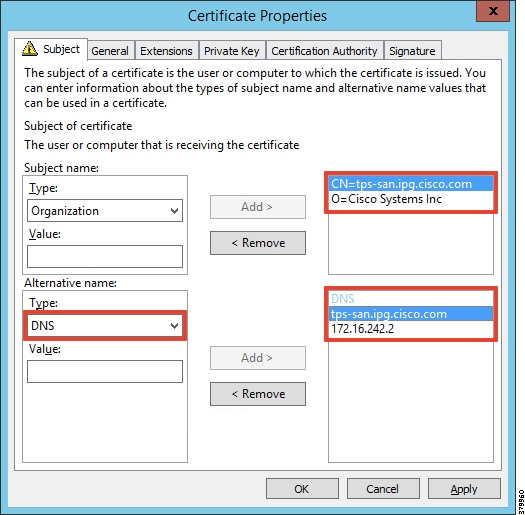
The Subject Name is the Common Name that must be set to the FQDN of the PnP Proxy. The Subject Alternative Name must be set to the FQDN of the PnP Proxy, along with the optional IP address. The Subject Alternative Name is required for PnP to work. The enrolled certificate is exported as PnP-TPS.pfx and is protected with a password.
Certificate Creation for Bootstrapping FND
The FND certificate must be created with both the Subject Name and Subject Alternative Name fields populated.
Figure 11 FND Certificate Parameters for PnP Bootstrapping
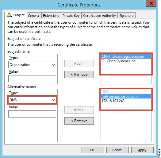
The Subject Name is the Common Name that must be set to the FQDN of the PnP Server. The Subject Alternative Name must be set to the FQDN of the PnP Server, along with the optional IP address. The Subject Alternative Name is required for PnP to work. The enrolled certificate is exported as PnP-FND.pfx and is protected with a password.
Installation of Bootstrapping TPS
The bootstrapping procedure in this implementation considers the use of TPS as PnP Proxy.
Note: As TPS is used in this implementation, TPS would represent itself as the PnP server for the IoT Gateways. Therefore, TPS is referred to as the PnP Proxy. For installation of TPS, please refer to the detailed steps covered under the section “Implementing Tunnel Provisioning Server” of the Cisco FAN-Headend Deep Dive Implementation and FAN Use Cases Guide.
TPS Certificate Installation on the Bootstrapping TPS
For installation of the certificate on the Bootstrapping TPS, please refer to the detailed steps covered under the section “Certificate Enrollment Phase for TPS Proxy Server” of the Cisco FAN - Headend Deep Dive Implementation and FAN Use Cases Guide.
Note: Please use PnP-TPS.pfx while enrolling the certificate on the TPS.
The following are the brief steps:
# To view the content of the "Pnp-TPS.pfx" certificate:
Cisco SUDI Certificate Installation on the Bootstrapping TPS
Cisco SUDI CA can be installed into the cgms_keystore of TPS using the following command:
The Cisco SUDI CA file "cisco-sudi-ca.pem" can be fetched from the FND, from the following location “/opt/cgms/server/cgms/conf/ciscosudi/cisco-sudi-ca.pem”
Installation of Bootstrapping FND
For installation of FND, please refer to the detailed steps covered under the section “Implementing Field Network Director” of the Cisco FAN-Headend Deep Dive Implementation and FAN Use Cases Guide.
FND Certificate Installation on the Bootstrapping FND
For installation of the certificate on the Bootstrapping FND, please refer to the detailed steps covered under the section “Certificate Enrollment onto FND's Keystore” of the Cisco FAN Headend Deep Dive Implementation and FAN Use Cases Guide.
Note: Please use PnP-FND.pfx while enrolling the certificate on the FND.
Cisco SUDI Certificate Installation on the Bootstrapping FND
Cisco SUDI CA can be installed into the cgms_keystore of FND using the following command:
Configuration of Bootstrapping TPS
This section covers the configuration steps and the final verification steps on the TPS.
TPS Proxy Properties Configuration TPS
Proxy Properties file needs to be configured with the following details:
■![]() inbound-bsproxy-destination: Address to which the bootstrapping requests be forwarded.
inbound-bsproxy-destination: Address to which the bootstrapping requests be forwarded.
■![]() enable-bootstrap-service: Is bootstrapping service enabled/disabled?
enable-bootstrap-service: Is bootstrapping service enabled/disabled?
■![]() bootstrap-proxy-listen-port: Port on which the PnP Proxy must be listening for processing bootstrapping requests (default port is 9125).
bootstrap-proxy-listen-port: Port on which the PnP Proxy must be listening for processing bootstrapping requests (default port is 9125).
Name resolution entries have to be present for FND FQDN in the /etc/hosts file.
Mandatory Verification Checks on TPS Proxy
The verification checks include the following:
■![]() FND FQDN entry in /etc/hosts.
FND FQDN entry in /etc/hosts.
■![]() TPS must have three certificates installed into the cgms_keystore:
TPS must have three certificates installed into the cgms_keystore:
–![]() Certificate signed by Utility PKI for TPS (with private key)
Certificate signed by Utility PKI for TPS (with private key)
–![]() Public Certificate of the Utility PKI CA server
Public Certificate of the Utility PKI CA server
–![]() Public Certificate of the Cisco SUDI CA
Public Certificate of the Cisco SUDI CA
■![]() Hostname consistency with the certificate.
Hostname consistency with the certificate.
■![]() There shouldn't be any unreachable name servers in /etc/resolv.conf.
There shouldn't be any unreachable name servers in /etc/resolv.conf.
■![]() NTP daemon should be running. Time should be synchronized.
NTP daemon should be running. Time should be synchronized.
■![]() Necessary firewall ports must have been opened up, if the firewall/iptables/ip6tables are enabled:
Necessary firewall ports must have been opened up, if the firewall/iptables/ip6tables are enabled:
–![]() TCP Port 9125 to process http communication
TCP Port 9125 to process http communication
–![]() TCP port 9120 to process https communication FND FQDN entry in /etc/hosts:
TCP port 9120 to process https communication FND FQDN entry in /etc/hosts:
TPS must have three certificates installed into the cgms_keystore:
■![]() The certificate entry 'root' represents the Utility PKI CA certificate.
The certificate entry 'root' represents the Utility PKI CA certificate.
■![]() The certificate entry 'sudi' represents the Cisco SUDI CA certificate.
The certificate entry 'sudi' represents the Cisco SUDI CA certificate.
■![]() The certificate entry 'cgms' represents the private certificate of the TPS server signed by the (custom) Utility PKI CA server.
The certificate entry 'cgms' represents the private certificate of the TPS server signed by the (custom) Utility PKI CA server.
Hostname should match certificate Common Name/SAN:
Note: No unreachable name servers should exist. Either the name servers should be present and reachable or they should be empty. Any unreachable name server address entry must be taken care or removed under the network interface configuration.
NTP daemon should be running. Time should be synchronized:
Note: The TPS server should be time synchronized. Otherwise, the https communication from the IoT Gateway might not reach the TPS Proxy Application.
Configuration of Bootstrapping FND
This section covers the configuration steps and the final verification steps on the FND.
The CGMS Properties file needs to be configured with the following details:
■![]() proxy-bootstrap-ip—Address of the PnP Proxy from which the bootstrapping requests are processed
proxy-bootstrap-ip—Address of the PnP Proxy from which the bootstrapping requests are processed
■![]() enable-bootstrap-service—Enable/Disable the bootstrapping service
enable-bootstrap-service—Enable/Disable the bootstrapping service
■![]() bootstrap-fnd-alias—The trust point alias to be used during bootstrapping of the IoT Gateway
bootstrap-fnd-alias—The trust point alias to be used during bootstrapping of the IoT Gateway
■![]() ca-fingerprint—fingerprint of the 'root' trustpoint
ca-fingerprint—fingerprint of the 'root' trustpoint
Name resolution entries have to be present for TPS FQDN in the /etc/hosts file.
Mandatory Verification Checks on FND
Verification checks include the following:
■![]() TPS FQDN entry in the /etc/hosts file.
TPS FQDN entry in the /etc/hosts file.
■![]() FND must have three certificates installed into the cgms_keystore:
FND must have three certificates installed into the cgms_keystore:
–![]() Certificate signed by Utility PKI for FND (with private key)
Certificate signed by Utility PKI for FND (with private key)
–![]() Public Certificate of the Utility PKI CA server
Public Certificate of the Utility PKI CA server
–![]() Public Certificate of the Cisco SUDI CA
Public Certificate of the Cisco SUDI CA
■![]() Hostname must be consistent with the certificate.
Hostname must be consistent with the certificate.
■![]() No unreachable name servers in /etc/resolv.conf should exist.
No unreachable name servers in /etc/resolv.conf should exist.
■![]() NTP daemon should be running. Time should be synchronized.
NTP daemon should be running. Time should be synchronized.
■![]() Necessary firewall ports must have been opened up if the firewall/iptables/ip6tables are enabled:
Necessary firewall ports must have been opened up if the firewall/iptables/ip6tables are enabled:
–![]() TCP Port 9125 to process http communication
TCP Port 9125 to process http communication
–![]() TCP port 9120 to process https communication
TCP port 9120 to process https communication
TPS/FND FQDN entry in the /etc/hosts file:
FND must have three certificates installed into the cgms_keystore:
■![]() The certificate entry 'root' represents the Utility PKI CA certificate.
The certificate entry 'root' represents the Utility PKI CA certificate.
■![]() The certificate entry 'sudi' represents the Cisco SUDI CA certificate.
The certificate entry 'sudi' represents the Cisco SUDI CA certificate.
■![]() The certificate entry 'cgms' represents the private certificate of the FND server signed by the (custom) Utility PKI CA server.
The certificate entry 'cgms' represents the private certificate of the FND server signed by the (custom) Utility PKI CA server.
Hostname should match the certificate Common Name/SAN:
Note: No unreachable name servers should exist. Either the name servers should be present and reachable or they should be empty. Any unreachable name server address entry must be taken care or removed under the network interface configuration:
NTP daemon should be running. Time should be synchronized:
Note: The FND server should be time synchronized. Otherwise, the https communication from the IoT Gateway might not reach the FND (cgms) application.
A sample csv file that can be imported into FND for bootstrapping of IoT Gateway is shown below:
administrator,<encrypted_pwd>,IR809_ JMX1941X00B,ipg.cisco.com,flash:/ir800-universalk9
Note: Ensure that there aren’t any blank spaces while using this csv file.
Figure 12 Bootstrapping CSV Import at Bootstrapping FND
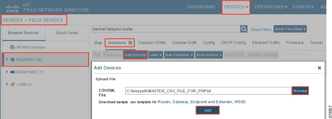
1.![]() From Devices > Field Devices, click Router in the left pane.
From Devices > Field Devices, click Router in the left pane.
2.![]() Click the Inventory tab on the middle pane.
Click the Inventory tab on the middle pane.
4.![]() Browse the csv file created in the previous step.
Browse the csv file created in the previous step.
5.![]() Then click Add to import the IoT Gateway CSV list into the bootstrapping FND.
Then click Add to import the IoT Gateway CSV list into the bootstrapping FND.
DHCP Server-Assisted PnP Provisioning
This section is discussed in the following phases:
■![]() Bootstrapping in the IPv4 Network
Bootstrapping in the IPv4 Network
Prerequisites
PnP Proxy must be reachable either over the LAN or over the WAN/Internet. As TPS is used in this implementation, TPS acts as the PnP server for the IoT Gateways. The DHCP server advertises TPS details in place of the PnP server details.
Bootstrapping in the IPv4 Network
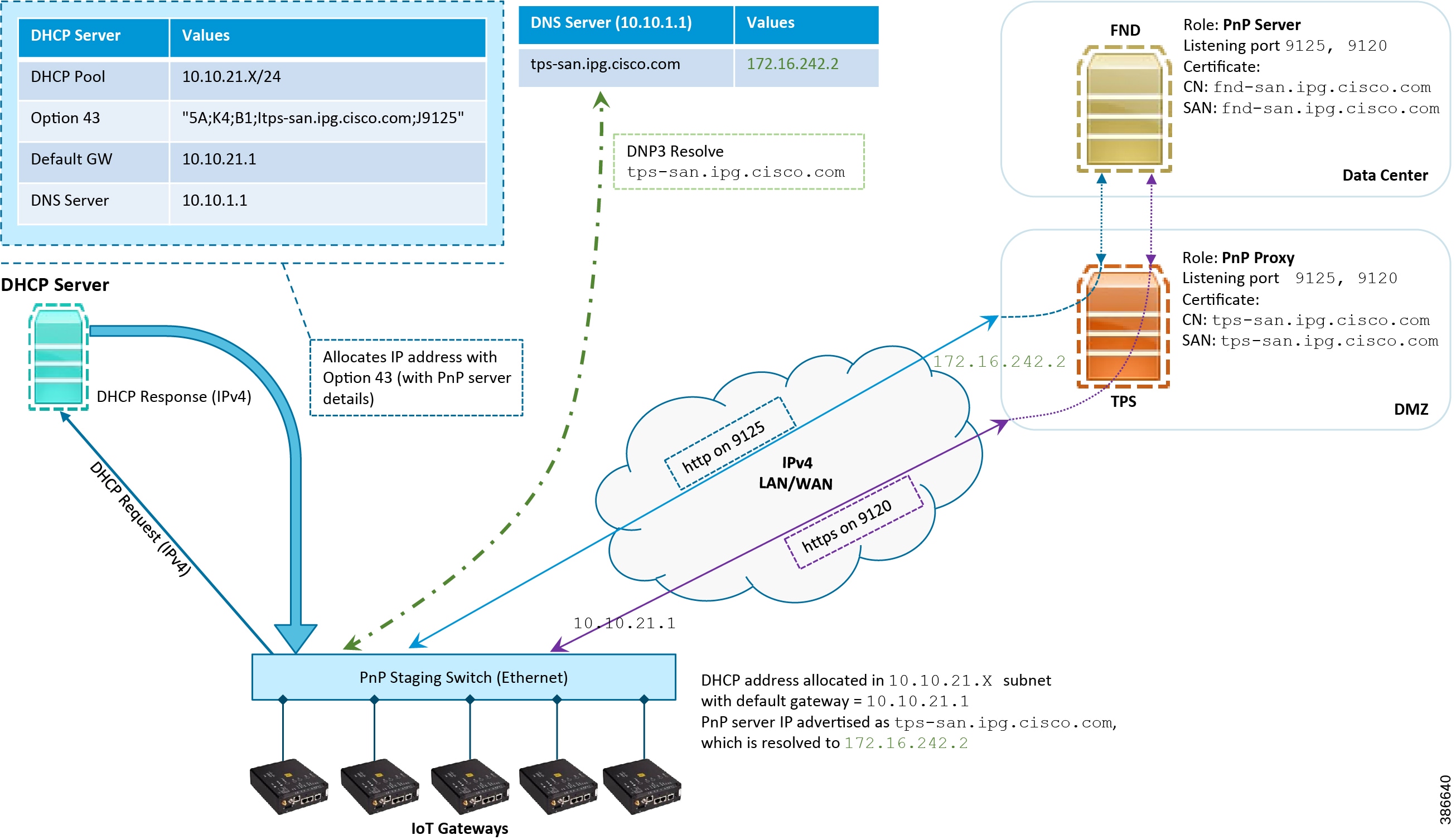
This section discusses the DHCP server-assisted bootstrapping of the IoT Gateways over the IPv4 network. In Figure 13, IoT Gateways obtain the IP address dynamically from the DHCP server along with details of the PnP server (which, in this case, is actually that of PnP Proxy, as TPS is deployed).
■![]() The PnP server details are received using DHCP option 43.
The PnP server details are received using DHCP option 43.
■![]() The PnP agent (residing on the IoT Gateway) then reaches out to PnP Proxy over IPv4 LAN/WAN network over http on port 9125 and then over https on port 9120.
The PnP agent (residing on the IoT Gateway) then reaches out to PnP Proxy over IPv4 LAN/WAN network over http on port 9125 and then over https on port 9120.
Figure 13 DHCP Server-Assisted Bootstrapping of IoT Gateways over IPv4 Network
Bootstrapping in the IPv6 Network
This section discusses the DHCP server-assisted bootstrapping of the IoT Gateways over the IPv6 network.
■![]() IoT Gateways obtains the IP address dynamically from the DHCP server along with details of the PnP server (which, in this case, is actually that of PnP Proxy, as TPS is deployed).
IoT Gateways obtains the IP address dynamically from the DHCP server along with details of the PnP server (which, in this case, is actually that of PnP Proxy, as TPS is deployed).
■![]() The PnP server details are received using DHCP option 9.
The PnP server details are received using DHCP option 9.
■![]() The PnP agent (residing on the IoT Gateway) then reaches out to PnP Proxy over IPv6 LAN/WAN network over http on port 9125 and then over https on port 9120.
The PnP agent (residing on the IoT Gateway) then reaches out to PnP Proxy over IPv6 LAN/WAN network over http on port 9125 and then over https on port 9120.
Logical Call Flow
This section discusses the logical call flow sequence with the DHCP server-assisted bootstrapping of the IoT Gateways over the IPv4/IPv6 network. Figure 14 shows the following actors:
Figure 14 DHCP Server-Assisted Bootstrapping of IoT Gateways—Logical Call Flow
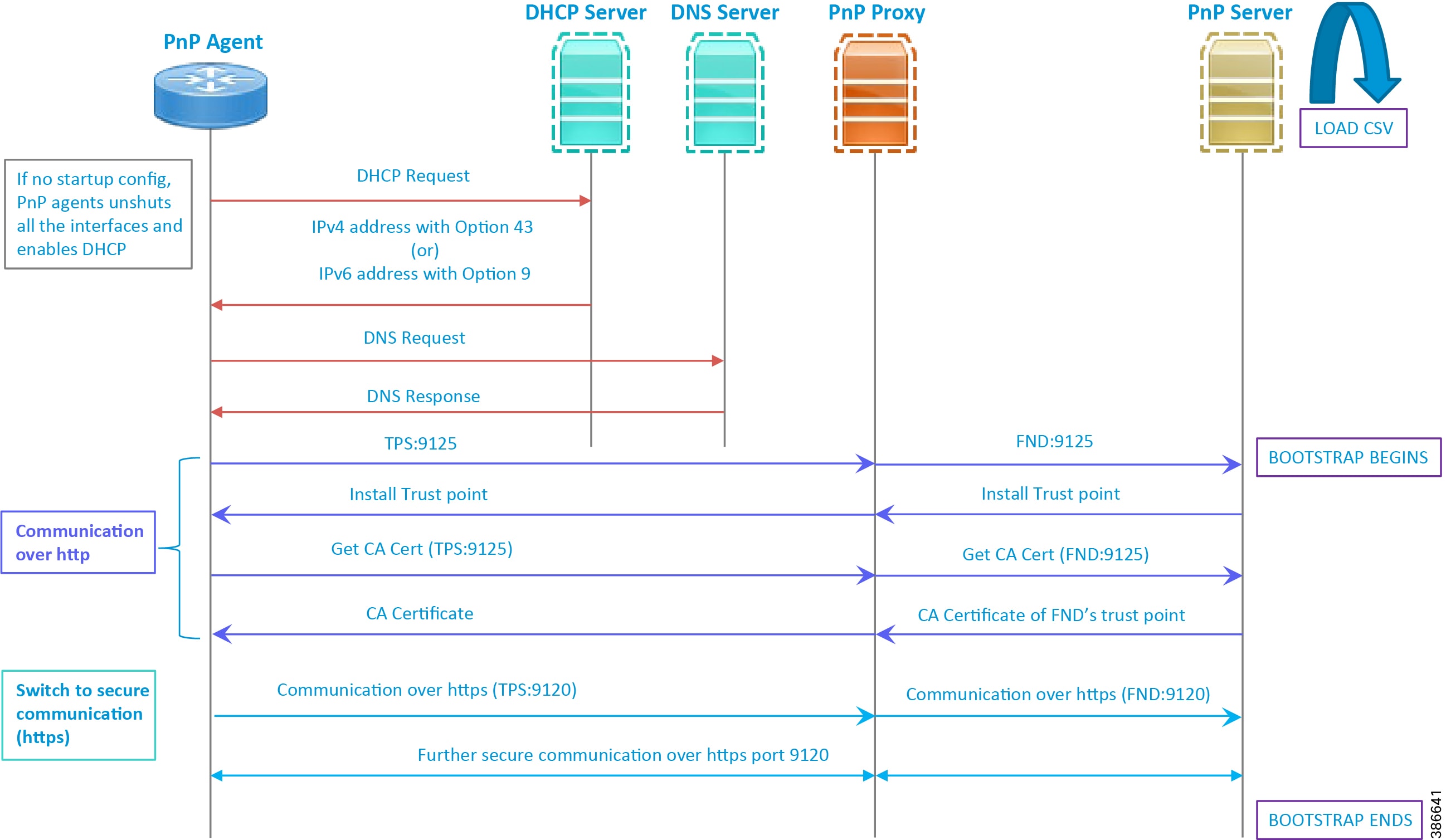
1.![]() When the IoT Gateway is powered on, the PnP Agent on the IoT Gateway checks for the presence of the startup configuration. If the startup configuration is not found, then the PnP agent performs “no shut" and enables DHCP on all the interfaces.
When the IoT Gateway is powered on, the PnP Agent on the IoT Gateway checks for the presence of the startup configuration. If the startup configuration is not found, then the PnP agent performs “no shut" and enables DHCP on all the interfaces.
2.![]() The IOS on the IoT Gateway sends out a DHCP request, which reaches the DHCP server (either directly or with the help of DHCP relay agent).
The IOS on the IoT Gateway sends out a DHCP request, which reaches the DHCP server (either directly or with the help of DHCP relay agent).
3.![]() The DHCP server responds back with the IPv4 address along with option 43, or the IPv6 address along with option 9. The option contains the FQDN of the PnP server to talk to (for example, tps-san.ipg.cisco.com) and the port number (for example, 9125) on which the PnP Proxy/Server is expected to be listening. The PnP server detail advertised as part of the DHCP option is the IP address of the PnP Proxy instead of the actual PnP server (with TPS deployed as part of the solution).
The DHCP server responds back with the IPv4 address along with option 43, or the IPv6 address along with option 9. The option contains the FQDN of the PnP server to talk to (for example, tps-san.ipg.cisco.com) and the port number (for example, 9125) on which the PnP Proxy/Server is expected to be listening. The PnP server detail advertised as part of the DHCP option is the IP address of the PnP Proxy instead of the actual PnP server (with TPS deployed as part of the solution).
4.![]() The IoT Gateway then sends out a name resolution request to DNS server to resolve the FQDN to its corresponding IPv4/IPv6 address.
The IoT Gateway then sends out a name resolution request to DNS server to resolve the FQDN to its corresponding IPv4/IPv6 address.
5.![]() The PnP Agent attempts its communication with the PnP Proxy over port 9125 (over http). PnP Proxy, in turn, communicates with the FND on port 9125. Bootstrapping begins at the FND from this point. The prerequisite to processing this bootstrapping request from the IoT Gateway is the addition of IoT Gateway details into the FND with the loading of the csv file.
The PnP Agent attempts its communication with the PnP Proxy over port 9125 (over http). PnP Proxy, in turn, communicates with the FND on port 9125. Bootstrapping begins at the FND from this point. The prerequisite to processing this bootstrapping request from the IoT Gateway is the addition of IoT Gateway details into the FND with the loading of the csv file.
6.![]() The FND installs the trust point on the IoT Gateway.
The FND installs the trust point on the IoT Gateway.
7.![]() The IoT Gateway sends out a Get CA Certificate request to PnP Proxy, which, in turn, proxies the communication to the FND. The FND would respond back with the CA certificate of the FND's trust point, which would then be installed on the IoT Gateway.
The IoT Gateway sends out a Get CA Certificate request to PnP Proxy, which, in turn, proxies the communication to the FND. The FND would respond back with the CA certificate of the FND's trust point, which would then be installed on the IoT Gateway.
The following PnP States would have transitioned at the FND:
8.![]() From this point onwards, the further communication switches over to https on port 9120. The IoT Gateway would communicate with the TPS IP on port 9120, which, in turn, is sent to the FND IP on port 9120. The rest of the IoT Gateway bootstrapping happens over this secure https communication established on port 9120.
From this point onwards, the further communication switches over to https on port 9120. The IoT Gateway would communicate with the TPS IP on port 9120, which, in turn, is sent to the FND IP on port 9120. The rest of the IoT Gateway bootstrapping happens over this secure https communication established on port 9120.
Note: Since the communication is over https, time synchronization and certificate parameters matching must be taken care of:
–![]() For example, if https://<TPS_FQDN>:9120 is attempted, then the certificate installed on the TPS must have CN/SAN configured with <TPS_FQDN>.
For example, if https://<TPS_FQDN>:9120 is attempted, then the certificate installed on the TPS must have CN/SAN configured with <TPS_FQDN>.
–![]() Similarly, if the https://<TPS_IP>:9120 is attempted, then the certificate installed on the TPS must also have CN/SAN configured with <TPS_IP>. Otherwise, SSL failure might occur and the https message from IoT Gateway might not reach the TPS Proxy Application on port 9120.
Similarly, if the https://<TPS_IP>:9120 is attempted, then the certificate installed on the TPS must also have CN/SAN configured with <TPS_IP>. Otherwise, SSL failure might occur and the https message from IoT Gateway might not reach the TPS Proxy Application on port 9120.
FND would transition through the following PnP states while the bootstrapping progresses:
–![]() PUSHING_BOOTSTRAP_CONFIG_FILE
PUSHING_BOOTSTRAP_CONFIG_FILE
–![]() PUSHING_BOOTSTRAP_CONFIG_VERIFY_HASH
PUSHING_BOOTSTRAP_CONFIG_VERIFY_HASH
9.![]() Bootstrapping would be complete with the "BOOTSTRAP_DONE" PnP State.
Bootstrapping would be complete with the "BOOTSTRAP_DONE" PnP State.
Custom PnP Profile for PnP Server
This section is discussed in the following phases:
■![]() Bootstrapping over IPv4 Network
Bootstrapping over IPv4 Network
■![]() Bootstrapping over IPv6 Network
Bootstrapping over IPv6 Network
As a gateway of last resort, if dynamic ways of learning the PnP Server are not an option, an option does exist to enable learning about the PnP server with minimal manual configuration.
Manual PnP profile configuration with PnP server details:
Note: Only the PnP Server detail is manually configured. Bootstrapping and Deployment (the rest of ZTD) still happens dynamically.
Prerequisites
■![]() The PnP server must be reachable either over the LAN or over the WAN/Internet.
The PnP server must be reachable either over the LAN or over the WAN/Internet.
■![]() As TPS is used in this implementation, TPS acts as a PnP server for the IoT Gateways.
As TPS is used in this implementation, TPS acts as a PnP server for the IoT Gateways.
Bootstrapping over IPv4 Network
This section focuses on the bootstrapping of the IoT Gateways over the IPv4 network in the absence of the DHCP server, DNS server, and Cisco Cloud redirector server to provide the PnP server details. IoT Gateways are informed about the PnP server detail directly through the Cisco IOS configuration commands.
In Figure 15, the manual PnP profile configuration on the IoT Gateways lets the IoT Gateways learn about the PnP server that should be reached out to and the desired PnP port number. For example, the custom PnP profile is configured to reach out to the PnP server ( tps-san.ipg.cisco.com) over the http on port 9125.
Figure 15 Custom PnP Profile-Assisted Bootstrapping of IoT Gateways over IPv4 Network
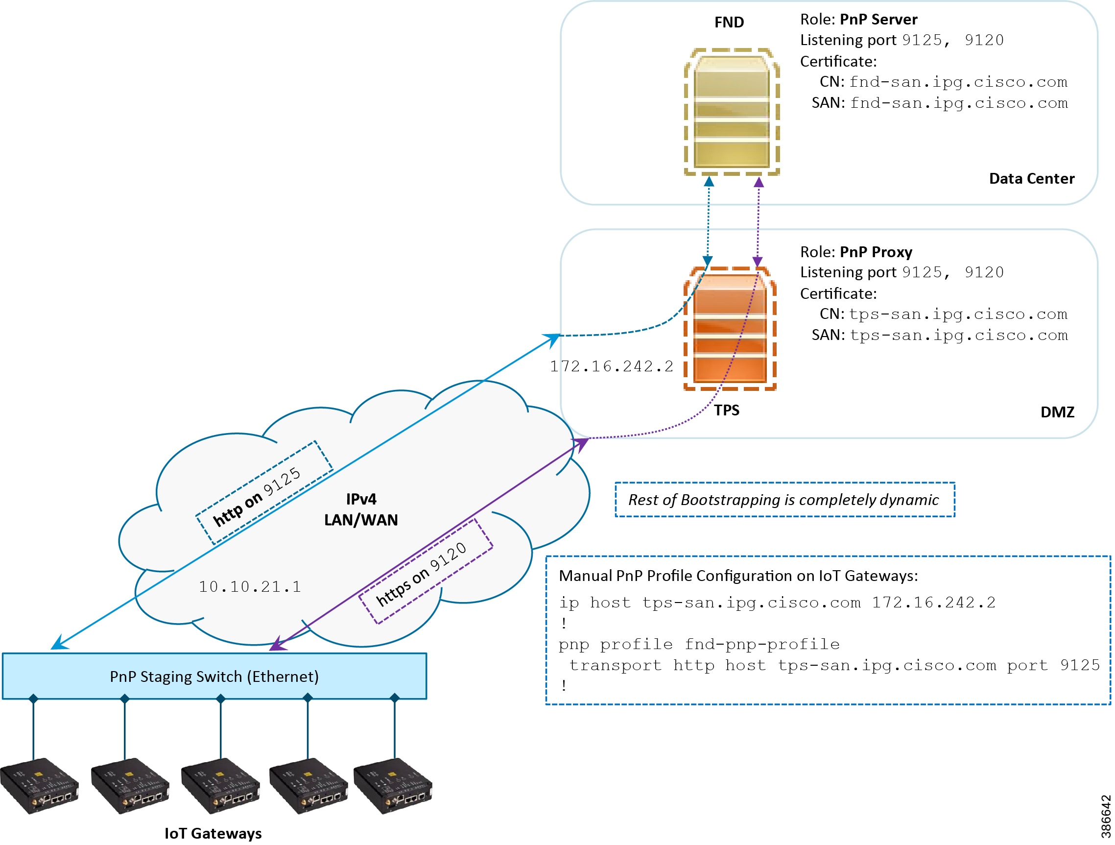
Based on the manual PnP profile configuration on the IoT Gateways, communication is initially established with PnP Proxy on http://tps-san.ipg.cisco.com:9125. Later, the communication is established with the PnP Proxy on https://tps-san.ipg.cisco.com:9120.
Note: Only the PnP server discovery is made manual. The rest of the bootstrapping procedure is the same as the DHCP server-assisted PnP provisioning discussed above.
Bootstrapping over IPv6 Network
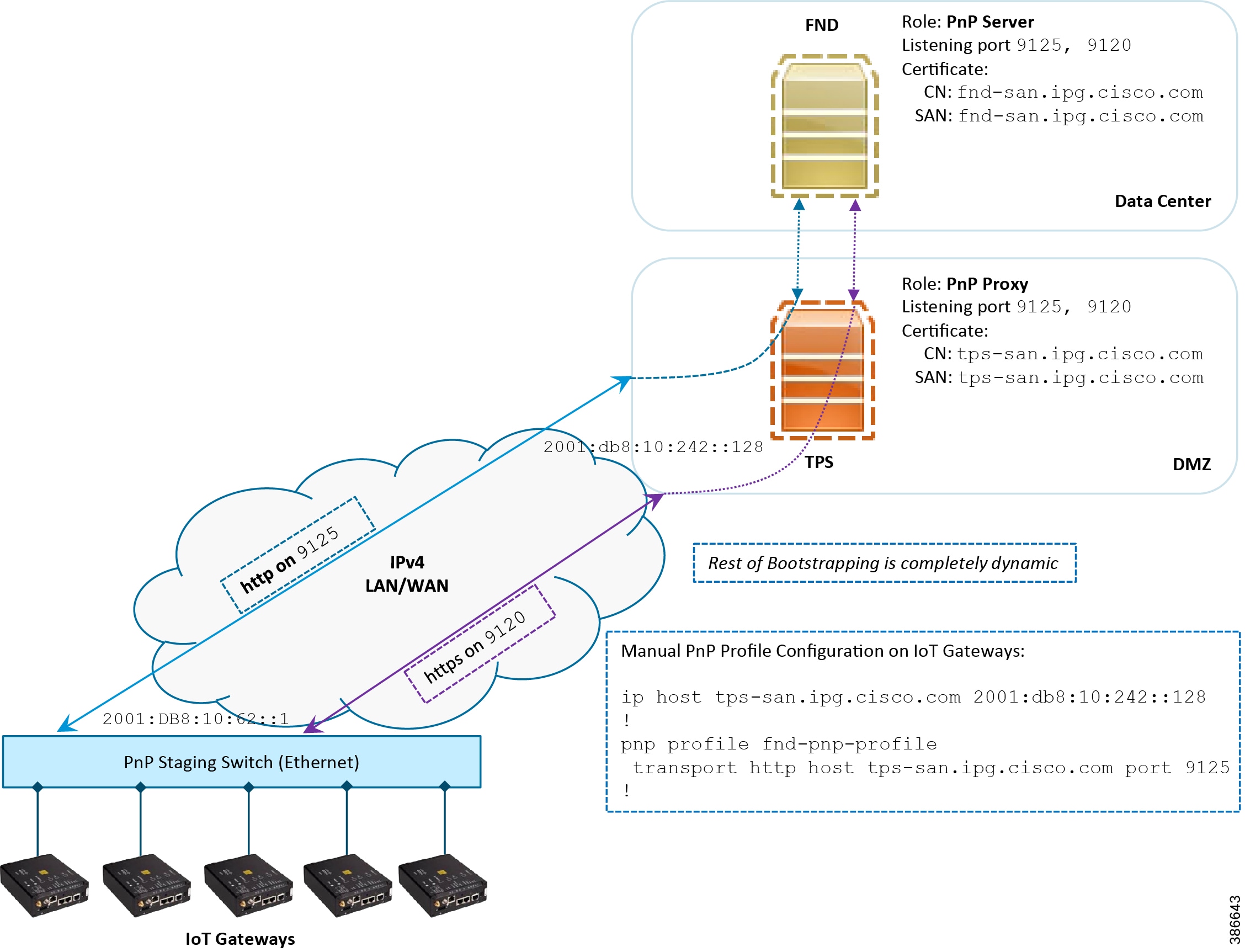
This section focuses on the bootstrapping of the IoT Gateways over the IPv6 network in the absence of the DHCP server, DNS server, and Cisco Cloud Redirector Server to provide the PnP server details. IoT Gateways are informed about the PnP server detail directly through the Cisco IOS configuration commands in order to enable bootstrapping of the IoT Gateways over the IPv6 network.
In Figure 16, based on the manual PNP profile configuration on the IoT Gateways, initially communication is established with the PnP Proxy on http://tps-san.ipg.cisco.com:9125. Later, the communication is established with PnP Proxy on https://tps-san.ipg.cisco.com:9120.
Name resolution happens to an IPv6 address, and the bootstrapping happens over an IPv6 network.
Note: Only the PnP server discovery is made manual. The rest of the bootstrapping procedure (PnP communication on port 9120 and 9125) is still dynamic.
Figure 16 Custom PnP Profile-Assisted Bootstrapping of IoT Gateways over IPv6 Network
Logical Call Flow
This section discusses the logical call flow sequence with the Custom PnP profile-assisted bootstrapping of the IoT Gateways over the IPv4/IPv6 network.
Figure 17 Custom PnP Profile-Assisted Bootstrapping of IoT Gateways—Logical Call Flow
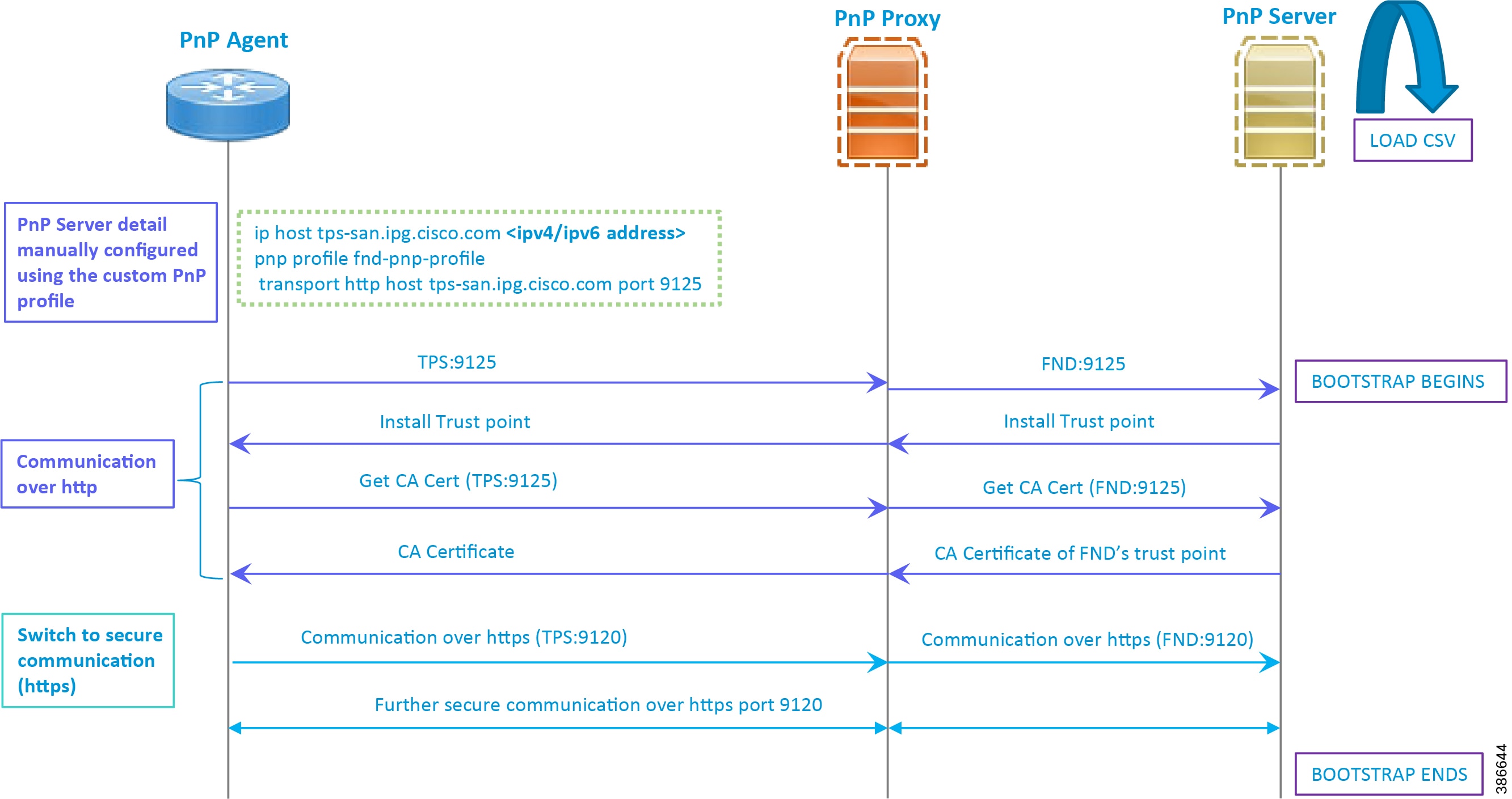
In Figure 17:
■![]() PnP server detail is learned out of the custom PnP profile, configured manually.
PnP server detail is learned out of the custom PnP profile, configured manually.
■![]() The IoT Gateway reaches out to the PnP server in the configuration, which is http://tps- san.ipg.cisco.com:9125.
The IoT Gateway reaches out to the PnP server in the configuration, which is http://tps- san.ipg.cisco.com:9125.
■![]() The communication reaches TPS, and is then sent to FND. Bootstrapping of the IoT Gateway begins at the FND.
The communication reaches TPS, and is then sent to FND. Bootstrapping of the IoT Gateway begins at the FND.
■![]() The rest of the procedure is exactly the same as the bootstrapping steps discussed as part of DHCP server-assisted PnP Provisioning.
The rest of the procedure is exactly the same as the bootstrapping steps discussed as part of DHCP server-assisted PnP Provisioning.
–![]() Initial communication happens on http://tps-san.ipg.cisco.com:9125
Initial communication happens on http://tps-san.ipg.cisco.com:9125
–![]() Later communication happens on https://tps-san.ipg.cisco.com:9120
Later communication happens on https://tps-san.ipg.cisco.com:9120
PnP Server Discovery through Cisco PnP Connect and Bootstrapping
Prerequisites
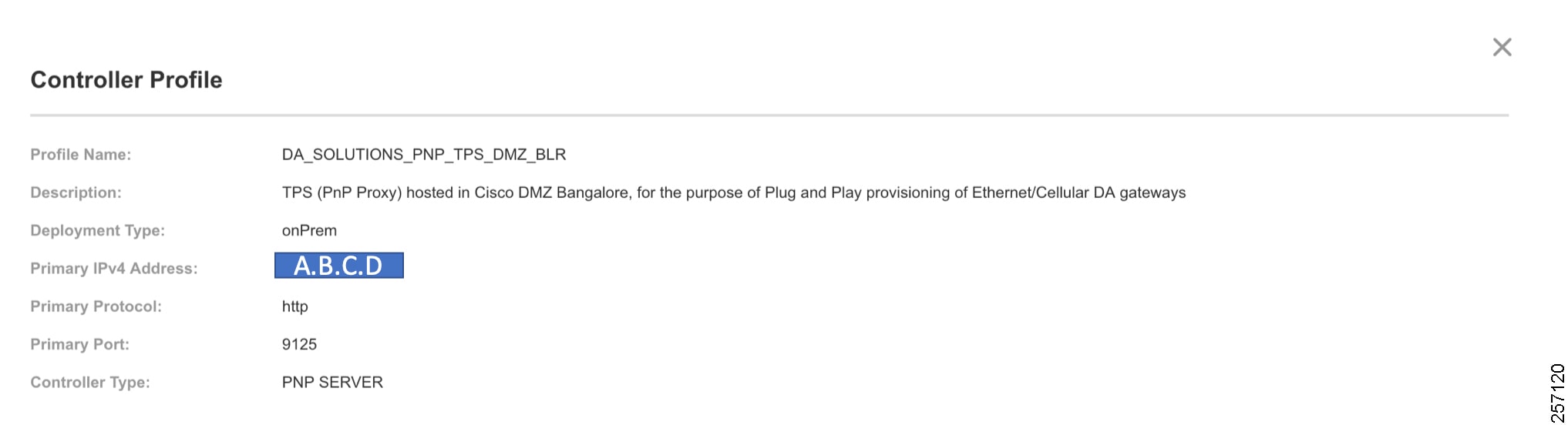
PnP Proxy must be reachable either over the WAN/Internet. As TPS is used in this implementation, TPS acts as the PnP server for the IoT Gateways. The controller profile on "software.cisco.com" should be configured with the correct TPS address. The controller profile advertises TPS details in place of the PnP server details.
To create the controller profile, login to software.cisco.com. Go to Network Plug and Play > Select controller profile from the toolbar and add the details.
Figure 18 shows the controller profile added on software.cisco.com.
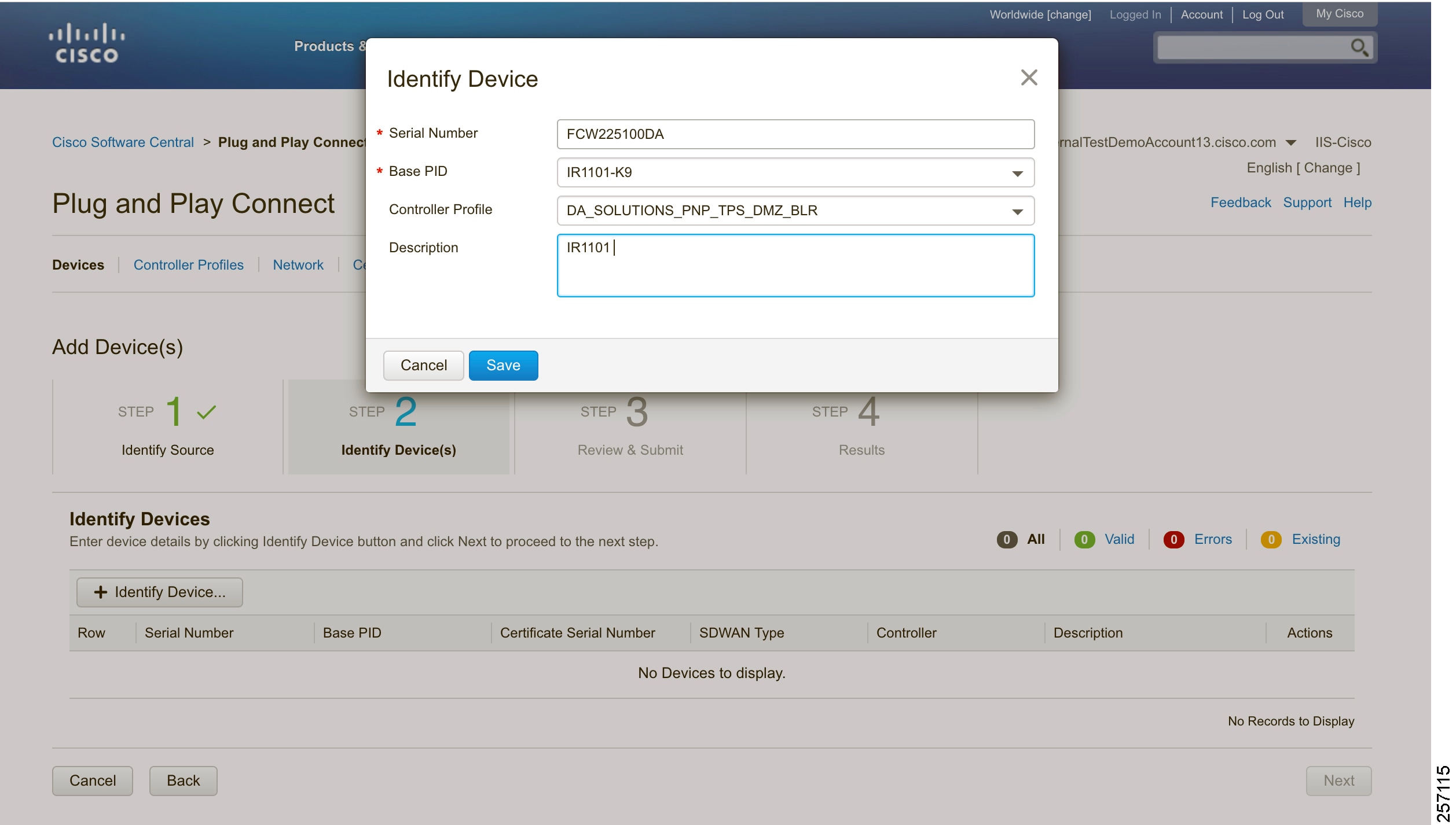
When a device is ordered through CCW, the device must be attached with the Smart account. For the PnP discovery to be successful using PnP Connect, a device must be added on the software.cisco.com portal. The device can be added either manually or by uploading a csv file. You can refer to "PnP Server Discovery Through Cisco PnP Connect" in the Cisco Distribution Automation Feeder Automation Design Guide. Figure 19 shows adding a device manually.
Figure 19 Manual Addition of Device
After manually adding the device in the PnP Connect portal, the request is yet to received from the device and the status for PnP redirection will be pending. This is shown in Figure 20.
Figure 20 PnP Redirect Pending after Manual Device Addition
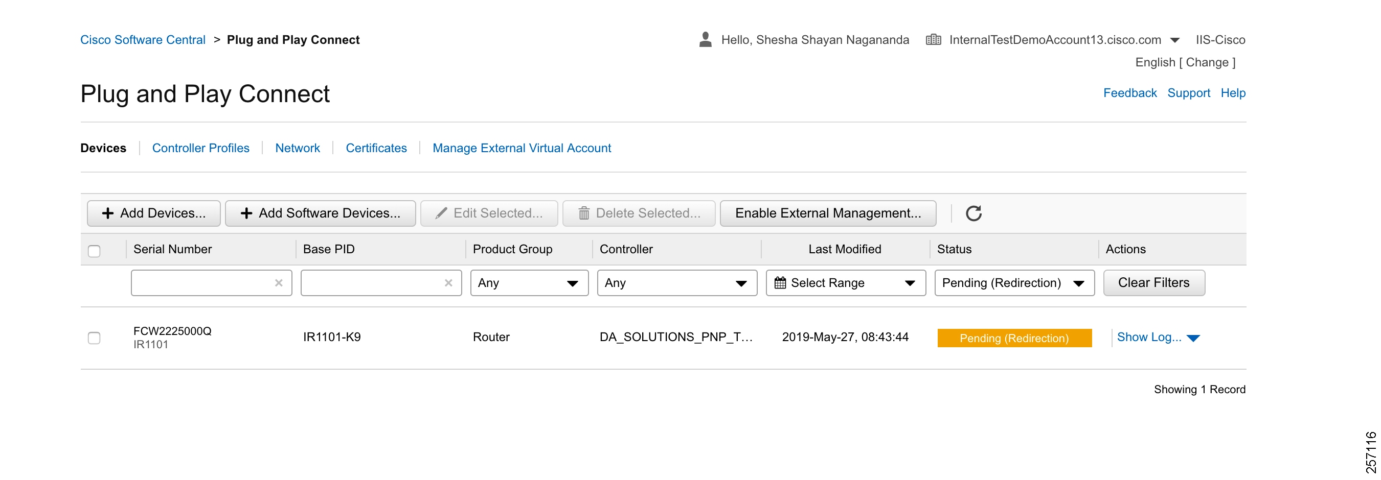
Finally, when the device is added successfully, it should be populated in the devices list as shown in Figure 20, which lists the devices for when the Redirect was successful.
Bootstrapping
This section discusses the PnP Connect-Assisted bootstrapping of the IoT Gateways over the IPv4 network.
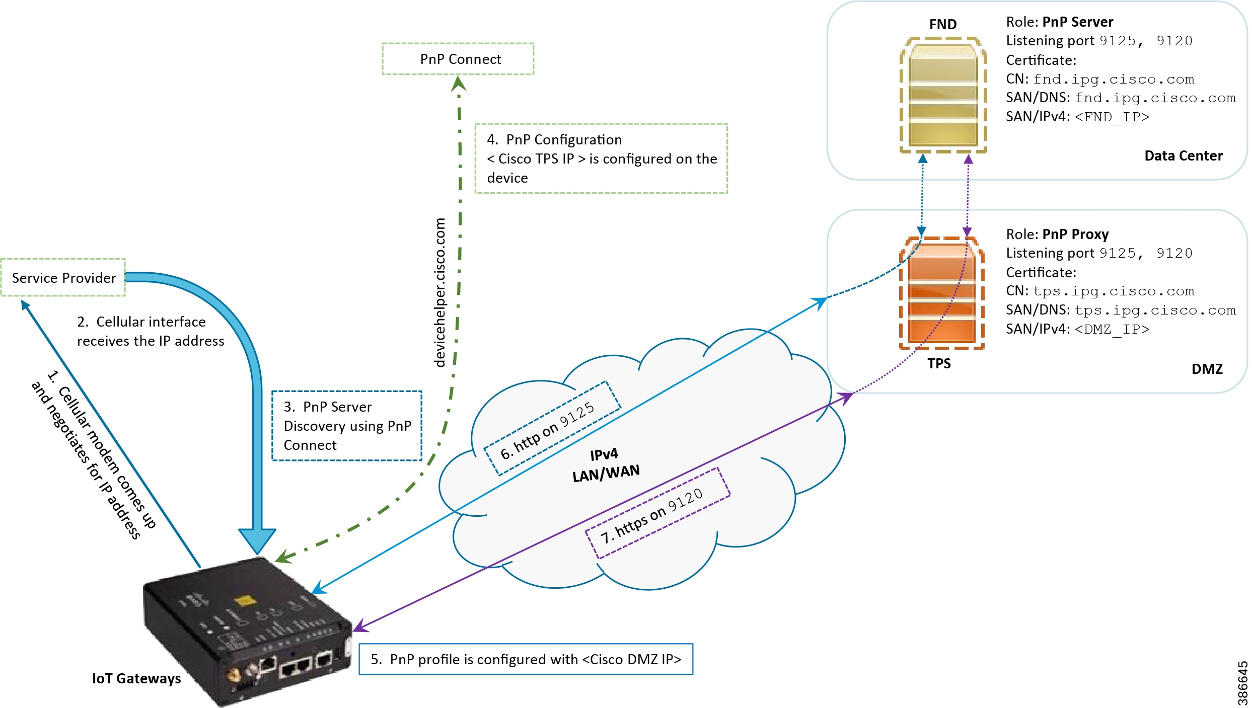
In Figure 21, IoT Gateways obtain the IP address dynamically from the service provider.
■![]() The PnP agent (residing on the IoT Gateway) then reaches out to PnP Proxy over IPv4 LAN/WAN network over http on port 9125 and then over https on port 9120.
The PnP agent (residing on the IoT Gateway) then reaches out to PnP Proxy over IPv4 LAN/WAN network over http on port 9125 and then over https on port 9120.
Figure 21 PnP Connect—Assisted Bootstrapping of IoT Gateways
Logical Call Flow
This section discusses the logical call flow sequence with the DHCP server-assisted bootstrapping of the IoT Gateways over the IPv4/IPv6 network.
The actors shown in Figure 22 are the following:
■![]() PnP Cloud Re-direction Service PnP Connect Portal
PnP Cloud Re-direction Service PnP Connect Portal
Figure 22 PnP Connect-Assisted Bootstrapping of IoT Gateways -Logical Call Flow
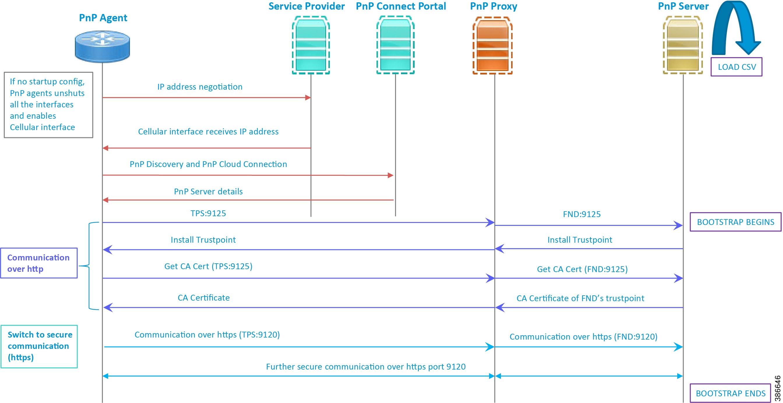
1.![]() When the IoT Gateway is powered on, the PnP Agent on the IoT Gateway checks for the presence of the startup configuration. If the startup configuration is not found, then the PnP agent performs "no shut" on all the cellular interfaces.
When the IoT Gateway is powered on, the PnP Agent on the IoT Gateway checks for the presence of the startup configuration. If the startup configuration is not found, then the PnP agent performs "no shut" on all the cellular interfaces.
2.![]() The IOS on the IoT Gateway sends out a request to the service provider.
The IOS on the IoT Gateway sends out a request to the service provider.
3.![]() The service provider responds back with the IPv4 address.
The service provider responds back with the IPv4 address.
4.![]() The IOT gateway proceeds for PnP server discovery and connects to the PnP cloud re-direction service connect portal. After successfully connecting the server devicehelper.cisco.com, the server PnP Connect portal sends the publicly reachable TPS DMZ IP(A.B.C.D) PnP proxy IP and the port number (9125) on which the proxy server is listening. The serial number of the gateway should be added to the Cisco Cloud PnP Connect portal for the re-direction service to be successful.
The IOT gateway proceeds for PnP server discovery and connects to the PnP cloud re-direction service connect portal. After successfully connecting the server devicehelper.cisco.com, the server PnP Connect portal sends the publicly reachable TPS DMZ IP(A.B.C.D) PnP proxy IP and the port number (9125) on which the proxy server is listening. The serial number of the gateway should be added to the Cisco Cloud PnP Connect portal for the re-direction service to be successful.
5.![]() Once the PnP discovery is successful, the PnP profile is configured on the device with the publicly reachable TPS DMZ IP. Once the profile is configured, the bootstrapping begins.
Once the PnP discovery is successful, the PnP profile is configured on the device with the publicly reachable TPS DMZ IP. Once the profile is configured, the bootstrapping begins.
6.![]() The rest of the procedure is exactly the same as the bootstrapping steps discussed as part of PnP server discovery through DHCP server.
The rest of the procedure is exactly the same as the bootstrapping steps discussed as part of PnP server discovery through DHCP server.
Bootstrapping Configuration Template on Bootstrapping FND
The bootstrapping template is a configuration template residing on the bootstrapping FND. As part of the bootstrapping procedure, when the bootstrapping request is received from the IoT Gateway, this bootstrap configuration template is used to derive the Cisco IOS configuration, which is then pushed onto the IoT Gateway.
Once this Cisco IOS configuration is pushed onto the IoT Gateway and copied onto a running configuration successfully, the bootstrapping is said to be SUCCESSFUL.
This bootstrapping of Cisco IoT Gateways from Cisco IoT FND (PnP Server) is entirely Zero Touch. This implementation section includes the following sections:
Creation of Bootstrap Configuration Template Group
This section covers the steps required for configuring the bootstrapping group.
Figure 23 CREATE Bootstrap—CONFIG—Tunnel Provisioning
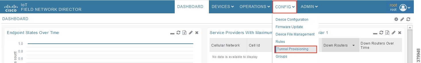
1.![]() From the CONFIG Menu, select the Tunnel Provisioning option.
From the CONFIG Menu, select the Tunnel Provisioning option.
Figure 24 CREATE Bootstrap—Add Group
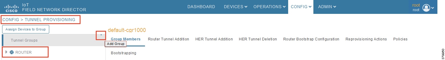
2.![]() With the Router Group selected in the left pane, click the "+" sign (Add Group icon) located on the top right of the left pane.
With the Router Group selected in the left pane, click the "+" sign (Add Group icon) located on the top right of the left pane.
Figure 25 CREATE Bootstrap—Add IPv4 Group
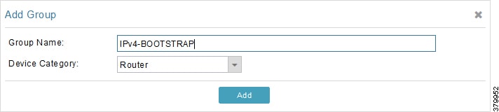
3.![]() Configure the group name IPv4-BOOTSTRAP, and click Add.
Configure the group name IPv4-BOOTSTRAP, and click Add.
Figure 26 CREATE Bootstrap—Add IPv6 Group
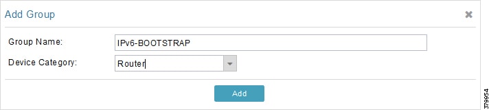
4.![]() Similarly, configure another group name IPv6-BOOTSTRAP for bootstrapping over the IPv6 network. Click Add.
Similarly, configure another group name IPv6-BOOTSTRAP for bootstrapping over the IPv6 network. Click Add.
Figure 27 CREATE Bootstrap—List of Bootstrap Groups
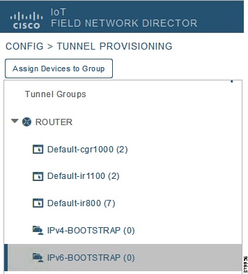
The two newly created bootstrapping groups are displayed in the left pane:
■![]() IPv4-BOOTSTRAP (Created to handle bootstrapping over the IPv4 network)
IPv4-BOOTSTRAP (Created to handle bootstrapping over the IPv4 network)
■![]() IPv6-BOOTSTRAP (Created to handle bootstrapping over the IPv6 network)
IPv6-BOOTSTRAP (Created to handle bootstrapping over the IPv6 network)
Moving Devices under the Bootstrapping Group
Multiple bootstrapping groups could be configured on the bootstrapping FND. IoT Gateways have to be moved under the correct group in order to have it bootstrapped with the appropriate configuration.
Complete the following steps to move IoT Gateways under the correct bootstrapping group.
Figure 28 CHANGE Tunnel Group—Device Under Default Group
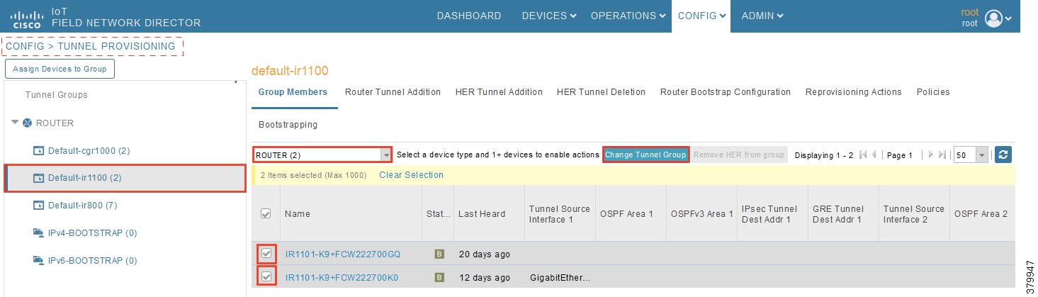
1.![]() In Figure 28, two IoT Gateways are under the default group. The devices need to be moved to the newly created IPv4-BOOTSTRAP group. In the middle pane, select the Router in the pull-down menu, select the IoT Gateways to be moved under the new bootstrapping group, and then click Change Tunnel Group.
In Figure 28, two IoT Gateways are under the default group. The devices need to be moved to the newly created IPv4-BOOTSTRAP group. In the middle pane, select the Router in the pull-down menu, select the IoT Gateways to be moved under the new bootstrapping group, and then click Change Tunnel Group.
Figure 29 CHANGE Tunnel Group—Pull-Down Menu
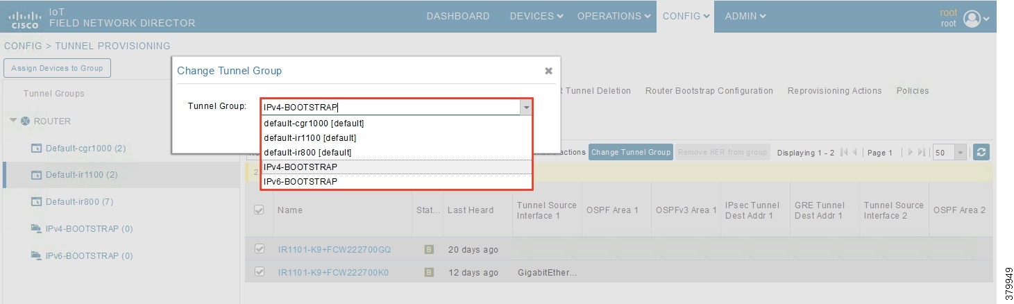
2.![]() Choose the correct bootstrap group IPv4-BOOTSTRAP. To perform bootstrapping over the IPv6 network, choose the IPv6-BOOTSTRAP tunnel group.
Choose the correct bootstrap group IPv4-BOOTSTRAP. To perform bootstrapping over the IPv6 network, choose the IPv6-BOOTSTRAP tunnel group.
Figure 30 CHANGE Tunnel Group—Select IPv4 Group
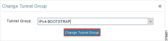
3.![]() With the appropriate bootstrap group chosen, click Change Tunnel Group to move the IoT Gateway from the default group to the desired group.
With the appropriate bootstrap group chosen, click Change Tunnel Group to move the IoT Gateway from the default group to the desired group.
Figure 31 CHANGE Tunnel Group—Updated IPv4 Group
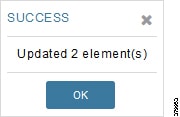
Device migration to the desired group was successful.
Figure 32 CHANGE Tunnel Group—Devices Moved under IPv4 Group
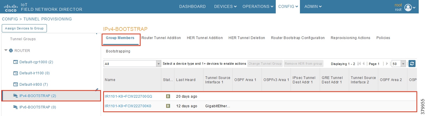
In Figure 30, it can be seen that IoT Gateways were moved under the correct bootstrapping group.
Router Bootstrap Configuration Groups—Populating Templates
This section shows where to populate the bootstrapping template in FND, and the template that needs to be chosen for bootstrapping of the IoT Gateways according to the network in which the IoT Gateway would be deployed (for example, IPv4/IPv6 network, located/not located behind NAT, etc).
Note: Working versions of bootstrapping templates can be found in Appendix A: PnP Profiles.
Figure 33 captures the Router Bootstrap Configuration section that needs to be populated for the purpose of bootstrapping.
Figure 33 Router Bootstrap Configuration
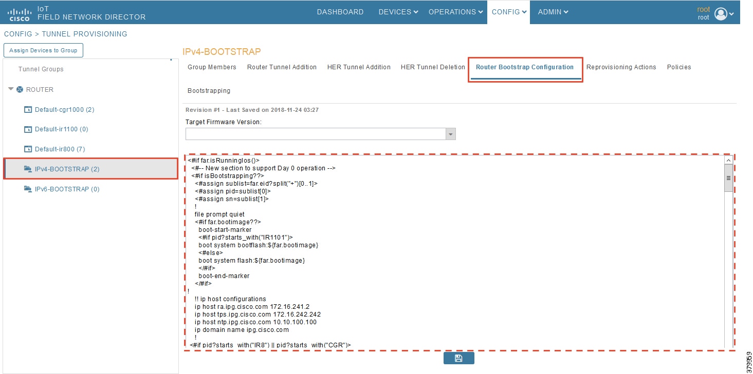
Every bootstrap group (referred as Tunnel Group in the left pane) can be populated with a unique Router bootstrap configuration.
With reference to Table 10, for bootstrapping the IoT Gateways for deployment over the IPv4 network:
■![]() If IoT Gateways are located behind NAT, then the bootstrapping template IPv4- BOOTSTRAP-NAT could be used.
If IoT Gateways are located behind NAT, then the bootstrapping template IPv4- BOOTSTRAP-NAT could be used.
■![]() If IoT Gateways are not located behind NAT, then the bootstrapping template IPv4- BOOTSTRAP could be used.
If IoT Gateways are not located behind NAT, then the bootstrapping template IPv4- BOOTSTRAP could be used.
Similarly, for bootstrapping the IoT Gateways for deployment over IPv6 network:
■![]() If IoT Gateways are located behind NAT, then the bootstrapping template IPv6- BOOTSTRAP-NAT could be used.
If IoT Gateways are located behind NAT, then the bootstrapping template IPv6- BOOTSTRAP-NAT could be used.
■![]() If IoT Gateways are not located behind NAT, then the bootstrapping template IPv6- BOOTSTRAP could be used.
If IoT Gateways are not located behind NAT, then the bootstrapping template IPv6- BOOTSTRAP could be used.
Deployment of the Cisco IoT Gateway
This section includes the following topics:
■![]() Deployment over IPv4 Cellular Network with NAT
Deployment over IPv4 Cellular Network with NAT
Prerequisites for Deployment
■![]() Cisco IoT Gateway should have gone through the bootstrapping procedure mentioned in Bootstrapping the IoT Gateway, with the device being part of the appropriate bootstrapping group.
Cisco IoT Gateway should have gone through the bootstrapping procedure mentioned in Bootstrapping the IoT Gateway, with the device being part of the appropriate bootstrapping group.
■![]() Bootstrapping is said to be complete, when the Cisco IOS Routers received the bootstrapping configuration from the Bootstrapping FND.
Bootstrapping is said to be complete, when the Cisco IOS Routers received the bootstrapping configuration from the Bootstrapping FND.
■![]() The bootstrapping status for the router on the Bootstrapping FND must be in ‘Bootstrapped’ state.
The bootstrapping status for the router on the Bootstrapping FND must be in ‘Bootstrapped’ state.
Deployment Infrastructure Readiness
■![]() Cisco IoT Gateway should be assigned an IPv4/IPv6 address dynamically over Ethernet/Cellular. If a static address needs to be used on the Cisco IoT Gateway, then assignment of address to the Cisco IoT Gateway's interface needs to be taken care as part of Bootstrapping.
Cisco IoT Gateway should be assigned an IPv4/IPv6 address dynamically over Ethernet/Cellular. If a static address needs to be used on the Cisco IoT Gateway, then assignment of address to the Cisco IoT Gateway's interface needs to be taken care as part of Bootstrapping.
Tip: If any extra configuration is required to receive IP address dynamically, the delta configuration should be fed back into the bootstrapping profile, that was used to bootstrap the IoT Gateway.
■![]() Cisco Field Area Network—Headend (DSO Control Center1) should be UP and running.
Cisco Field Area Network—Headend (DSO Control Center1) should be UP and running.
–![]() If it needs to be set up, the Cisco FAN-Headend Deep Dive Implementation and FAN Use Cases' guide could be referenced to set up the headend in the DSO Control Center or NOC.
If it needs to be set up, the Cisco FAN-Headend Deep Dive Implementation and FAN Use Cases' guide could be referenced to set up the headend in the DSO Control Center or NOC.
■![]() All the required headend components like the CA server (RSA), AAA, AD, Registration Authority, NOC TPS/FND, DHCP server, and HERs are expected to be up and running in the DSO Control Center.
All the required headend components like the CA server (RSA), AAA, AD, Registration Authority, NOC TPS/FND, DHCP server, and HERs are expected to be up and running in the DSO Control Center.
■![]() NOC TPS, RA, and HERs must have static IP addresses configured and should be reachable from the Cisco IoT Gateways that are located along the Distribution network.
NOC TPS, RA, and HERs must have static IP addresses configured and should be reachable from the Cisco IoT Gateways that are located along the Distribution network.
Note: If the prerequisites for deployment are addressed, ZTD of the IoT Gateways should happen successfully after the gateway is deployed at the desired location and powered on, with the Ethernet cable connected or the LTE SIM card inserted.
Deployment over IPv4 Cellular Network with NAT
Note: This section has no implementation steps. As the term "ZTD" states, it's a zero touch deployment. As long as bootstrapping happened successfully by having the IoT Gateway part of the correct bootstrapping group, this deployment should happen successfully with no manual steps.
Figure 34 captures the deployment steps for IoT Gateway over LTE Cellular.
Figure 34 Deployment over IPv4 Cellular Network
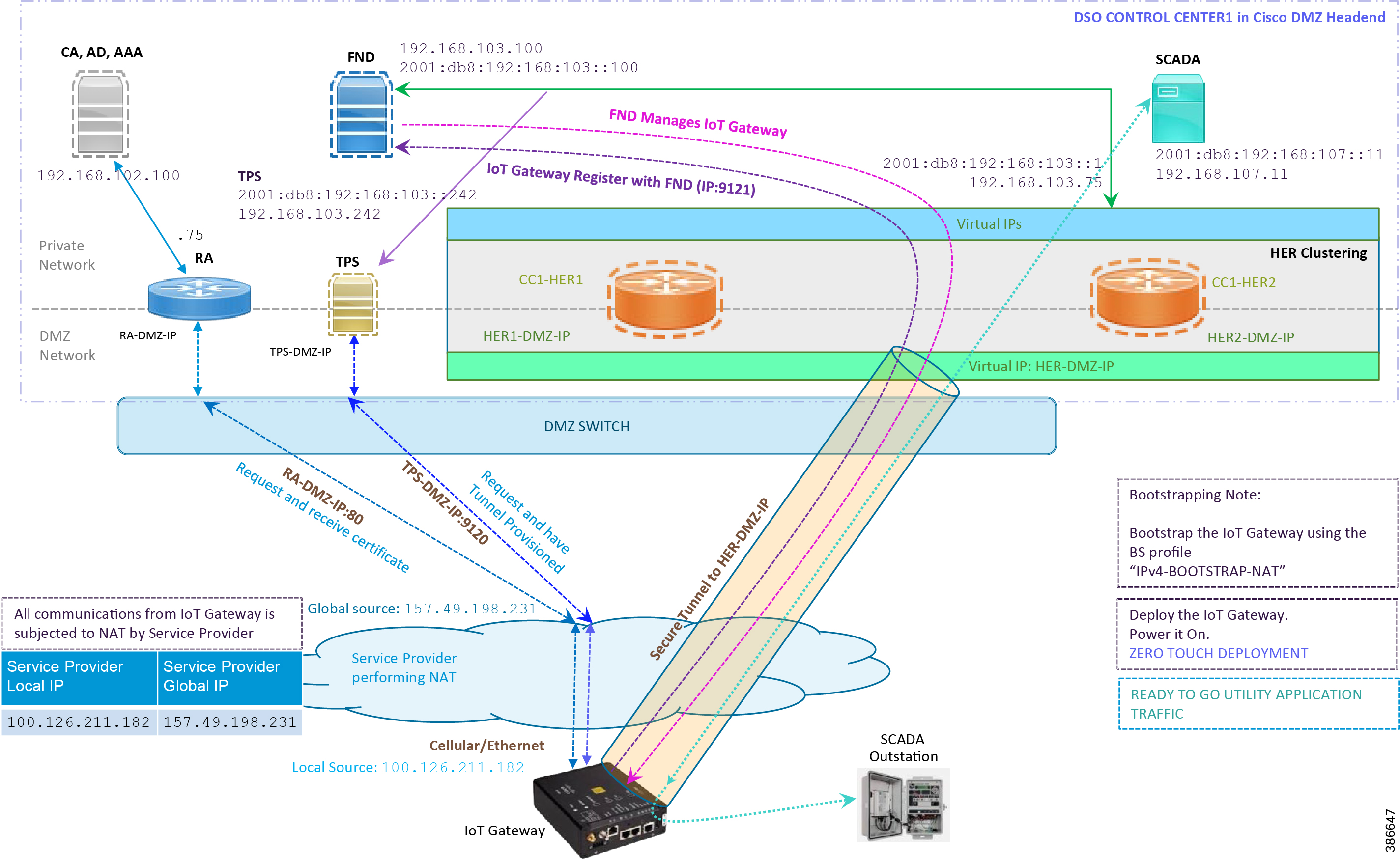
Note: This scenario has been validated with the headend located in the Cisco DMZ.
The following is the summary sequence of steps that occurs during the deployment:
1.![]() The IoT Gateway is powered on. When up, it obtains the IP address over LTE Cellular interface.
The IoT Gateway is powered on. When up, it obtains the IP address over LTE Cellular interface.
2.![]() The EEM Script for ZTD kicks in and waits for the time to be synchronized. Then, SCEP enrollment happens over port 80 with RA-DMZ-IP.
The EEM Script for ZTD kicks in and waits for the time to be synchronized. Then, SCEP enrollment happens over port 80 with RA-DMZ-IP.
3.![]() Once the certificate is received for the IoT Gateway (from the RA/CA), the ZTD script disables itself and activates the CGNA profile for tunnel provisioning (cgna initiator-profile cg-nms-tunnel).
Once the certificate is received for the IoT Gateway (from the RA/CA), the ZTD script disables itself and activates the CGNA profile for tunnel provisioning (cgna initiator-profile cg-nms-tunnel).
Note: "cgna initiator-profile cg-nms-tunnel" must be used when the IoT Gateway is behind NAT, whereas "cgna profile cg-nms-tunnel" must be used when no NAT exists between IoT Gateway and TPS. This CGNA profile is configured as part of bootstrapping.
4.![]() TPS/FND provisions the secure FlexVPN tunnel with the HER Cluster located in the DSO Control Center1.
TPS/FND provisions the secure FlexVPN tunnel with the HER Cluster located in the DSO Control Center1.
5.![]() As an overlay routing, FND and SCADA routes are advertised (by the HER) to the IoT Gateway through the secure FlexVPN tunnel.
As an overlay routing, FND and SCADA routes are advertised (by the HER) to the IoT Gateway through the secure FlexVPN tunnel.
6.![]() The IoT Gateway sends out a registration request to FND on port 9121. Once registered successfully, the IOT Gateway is remotely manageable from the FND.
The IoT Gateway sends out a registration request to FND on port 9121. Once registered successfully, the IOT Gateway is remotely manageable from the FND.
7.![]() As part of the device registration with the FND, FND also pushes ICT enablement configurations to the IoT Gateway, which enables the communication between the SCADA Master in the Control Center and the SCADA Outstation located in the Feeder Automation/Distribution Network.
As part of the device registration with the FND, FND also pushes ICT enablement configurations to the IoT Gateway, which enables the communication between the SCADA Master in the Control Center and the SCADA Outstation located in the Feeder Automation/Distribution Network.
Deployment over IPv4 Network without NAT
Note: This section has no implementation steps. As the term "ZTD" states, it's a zero touch deployment. As long as bootstrapping happened successfully by having the IoT Gateway part of the right bootstrapping group, this deployment should happen successfully with no manual steps.
Figure 33 captures the deployment steps for IoT Gateway without NAT over the IPv4 network.
Figure 35 Deployment over IPv4 Ethernet Network
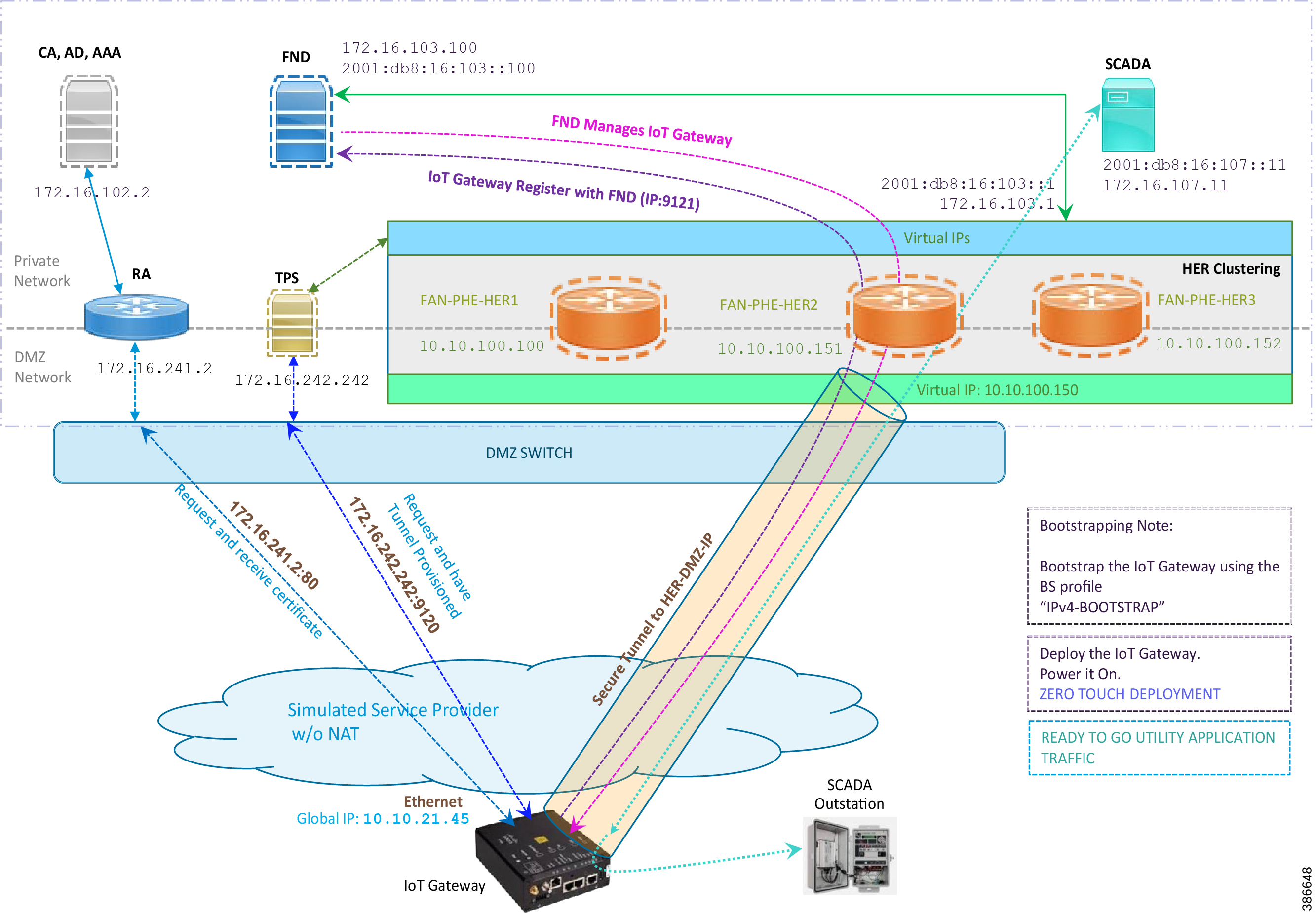
Note: This scenario has been validated with the headend located in the Engineering Lab.
The following is the summary sequence of steps that happens during the deployment:
1.![]() The IoT Gateway is powered on. When up, it obtains the IP address over the Ethernet interface.
The IoT Gateway is powered on. When up, it obtains the IP address over the Ethernet interface.
2.![]() The EEM Script for ZTD kicks in and waits for the time to be synchronized. Then, SCEP enrollment happens with RA IP (172.16.241.2) on port 80.
The EEM Script for ZTD kicks in and waits for the time to be synchronized. Then, SCEP enrollment happens with RA IP (172.16.241.2) on port 80.
3.![]() Once the certificate is received for the IoT Gateway (from the RA/CA), the ZTD script disables itself, and activates the CGNA profile for tunnel provisioning (cgna profile cg-nms- tunnel).
Once the certificate is received for the IoT Gateway (from the RA/CA), the ZTD script disables itself, and activates the CGNA profile for tunnel provisioning (cgna profile cg-nms- tunnel).
Note: "cgna profile cg-nms-tunnel" must be used when there is no NAT between IoT Gateway and TPS. This CGNA profile has already been configured as part of IoT Gateway bootstrapping. TPS/FND provisions secure FlexVPN tunnel with the HER Cluster located in the DSO Control Center1.
4.![]() As an overlay routing, FND (172.16.103.100 and 2001:db8:16:103::100) and SCADA (172.16.107.11 and 2001:db8:16:107::11) routes are advertised (by HER) to the IoT Gateway through the secure FlexVPN tunnel.
As an overlay routing, FND (172.16.103.100 and 2001:db8:16:103::100) and SCADA (172.16.107.11 and 2001:db8:16:107::11) routes are advertised (by HER) to the IoT Gateway through the secure FlexVPN tunnel.
5.![]() IoT Gateway sends out a registration request to FND IPv4 address 172.16.103.100 (or) IPv6 address 2001:db8:16:103::100 on port 9121. Once registered successfully, the IOT Gateway is remotely manageable from the FND.
IoT Gateway sends out a registration request to FND IPv4 address 172.16.103.100 (or) IPv6 address 2001:db8:16:103::100 on port 9121. Once registered successfully, the IOT Gateway is remotely manageable from the FND.
6.![]() As part of the device registration with the FND, FND also pushes ICT enablement configurations to the IoT Gateway, which enables the communication between SCADA Master in the Control Center and the SCADA Outstation located in the Feeder Automation/Distribution Network.
As part of the device registration with the FND, FND also pushes ICT enablement configurations to the IoT Gateway, which enables the communication between SCADA Master in the Control Center and the SCADA Outstation located in the Feeder Automation/Distribution Network.
Deployment over Native IPv6 Ethernet Network
Note: This section has no implementation steps. As the term "ZTD" states, it's a zero touch deployment. As long as bootstrapping happened successfully by having the IoT Gateway part of the right bootstrapping group, this deployment should happen successfully with no manual steps.
Figure 36 captures the deployment steps for the IoT Gateway over the Native IPv6 network.
Figure 36 Deployment over Native IPv6 Ethernet Network
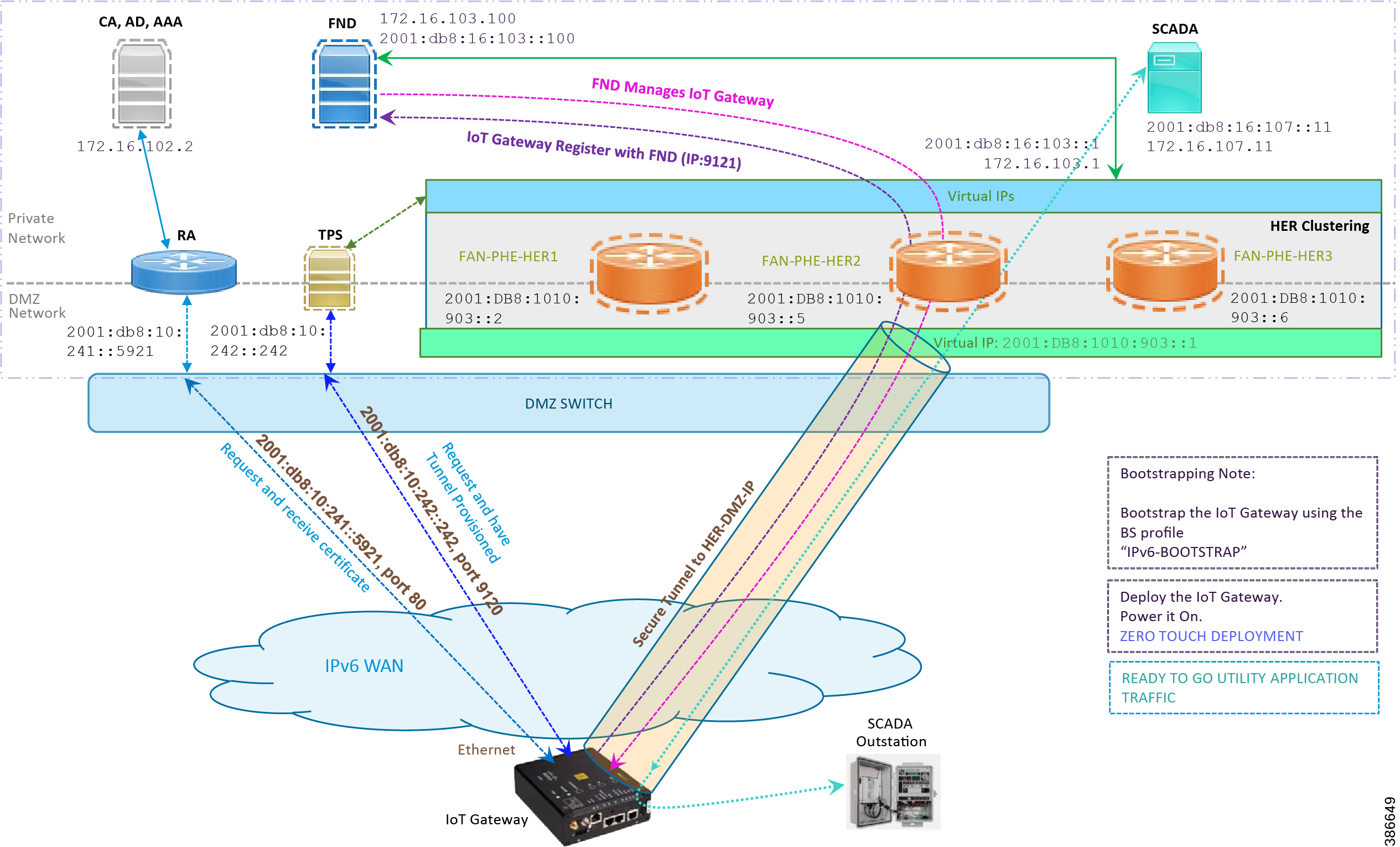
Note: This scenario has been validated with the headend located in the Engineering Lab over a native IPv6 network. It could be dual stack as well.
The following is the summary sequence of steps that happens during the deployment:
1.![]() The IoT Gateway is powered on. When up, it obtains the IPv6 address over the Ethernet interface.
The IoT Gateway is powered on. When up, it obtains the IPv6 address over the Ethernet interface.
2.![]() The EEM script for ZTD kicks in and waits for the time to be synchronized. Then, SCEP enrollment happens with RA IPv6 address (2001:db8:10:241::5921) on port 80.
The EEM script for ZTD kicks in and waits for the time to be synchronized. Then, SCEP enrollment happens with RA IPv6 address (2001:db8:10:241::5921) on port 80.
3.![]() IPv4 communication could be retained between RA and CA in the Control Center private network.
IPv4 communication could be retained between RA and CA in the Control Center private network.
4.![]() Once the certificate is received for the IoT Gateway (from the RA/CA), the ZTD script disables itself, and activates the CGNA profile for tunnel provisioning.
Once the certificate is received for the IoT Gateway (from the RA/CA), the ZTD script disables itself, and activates the CGNA profile for tunnel provisioning.
Note: "cgna initiator-profile cg-nms-tunnel" must be used when the IoT Gateway is behind NAT, whereas "cgna profile cg-nms-tunnel" must be used when there is no NAT between IoT Gateway and TPS. This CGNA profile has already been configured as part of the IoT Gateway bootstrapping.
5.![]() TPS/FND provisions secure the FlexVPN tunnel with the HER Cluster located in the DSO Control Center, over the Native IPv6 network.
TPS/FND provisions secure the FlexVPN tunnel with the HER Cluster located in the DSO Control Center, over the Native IPv6 network.
6.![]() As an overlay routing, FND (172.16.103.100 and 2001:db8:16:103::100) and SCADA (172.16.107.11 and 2001:db8:16:107::11) routes are advertised (by HER) to the IoT Gateway through the secure FlexVPN tunnel.
As an overlay routing, FND (172.16.103.100 and 2001:db8:16:103::100) and SCADA (172.16.107.11 and 2001:db8:16:107::11) routes are advertised (by HER) to the IoT Gateway through the secure FlexVPN tunnel.
7.![]() IoT Gateway sends out a registration request to FND IPv4 address 172.16.103.100 (or) IPv6 address 2001:db8:16:103::100 on port 9121. Once registered successfully, IOT Gateway is remotely manageable from the FND.
IoT Gateway sends out a registration request to FND IPv4 address 172.16.103.100 (or) IPv6 address 2001:db8:16:103::100 on port 9121. Once registered successfully, IOT Gateway is remotely manageable from the FND.
8.![]() As part of the device registration with the FND, FND also pushes ICT enablement configurations to the IoT Gateway, which enables the communication between SCADA Master in the Control Center and the SCADA Outstation located in the Feeder Automation/Distribution Network.
As part of the device registration with the FND, FND also pushes ICT enablement configurations to the IoT Gateway, which enables the communication between SCADA Master in the Control Center and the SCADA Outstation located in the Feeder Automation/Distribution Network.
Tunnel Provisioning Template Profiles
Tunnel Provisioning Template profiles, which are needed for Tunnel establishment, are captured in Appendix B: FND Zero Touch Deployment Profiles.
Device Configuration Template Profiles
Device Configuration Template profiles, which are needed for ICT SCADA Traffic enablement, are captured in Appendix C: Device Configuration Profiles.
Bootstrapping and ZTD of the Cisco IoT Gateway at the Deployment Location
This section describes the bootstrapping and Deployment of the Cisco IoT gateway at the deployed location. Unlike the previous section, one TPS and FND is sufficient to complete both bootstrapping and ZTD. Although the previous two sections and this section overlap, minor changes in the implementation of TPS and FND need to be done in order for the deployment to be successful.
This section, which covers the minor changes that have to be implemented in the headend setup, describes these phases:
Prerequisites
Prerequisites include the following:
■![]() TPS and FND server must be up and running.
TPS and FND server must be up and running.
■![]() This section focuses on portions required for TPS and FND to carry out both bootstrapping and ZTD.
This section focuses on portions required for TPS and FND to carry out both bootstrapping and ZTD.
■![]() Routing reachability over IPv4 and/or IPv6 networks from IoT Gateways to TPS.
Routing reachability over IPv4 and/or IPv6 networks from IoT Gateways to TPS.
Certificate Creation and Installation
This section captures the parameters that need to be considered while creating the certificate for the TPS and FND.
Note: For detailed instructions about certificate creation, please refer to the section "Creation of Certificate Templates and Certificates" of the Cisco FAN-Headend Deep Dive Implementation and FAN Use Cases Guide at the following URL:
■![]() https://docs.cisco.com/share/proxy/alfresco/url?docnum=EDCS-15726915
https://docs.cisco.com/share/proxy/alfresco/url?docnum=EDCS-15726915
Certificate Creation for TPS
The certificate for the TPS must be created with both the Subject Name and the Subject Alternative Name fields populated.
Figure 37 TPS Certificate Parameters
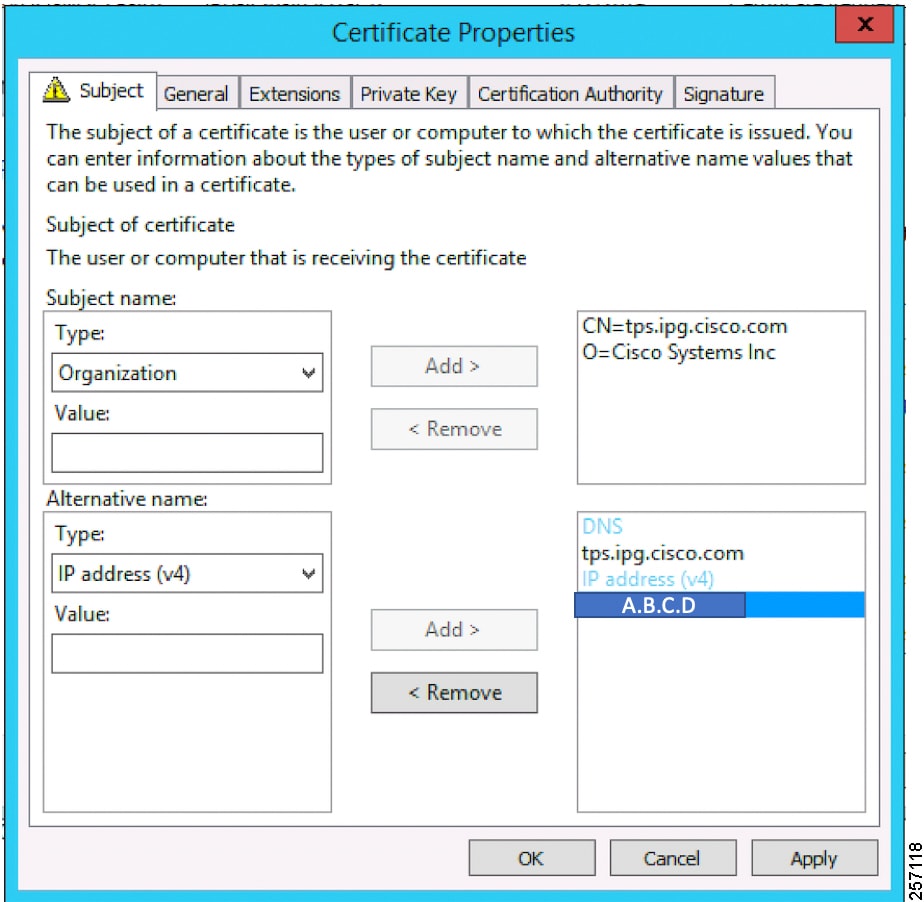
The Subject Name is the Common Name that must be set to the FQDN of the TPS.
The Subject Alternative Name must be set to the FQDN - tps.ipg.cisco.com of the TPS, along with the IP address (A.B.C.D - Public reachable DMZ IP). The Subject Alternative Name is required for PnP to work. The IP address must be reachable from the IoT Gateway. TPS is located in DMZ. The IP address is not optional in this implementation. FQDN is optional, but the IP address is not.
The enrolled certificate is exported as PnP-ZTD-TPS.pfx and is protected with a password.
Certificate Creation for FND
The FND certificate must be created with both the Subject Name and Subject Alternative Name fields populated.
Figure 38 FND Certificate Parameters
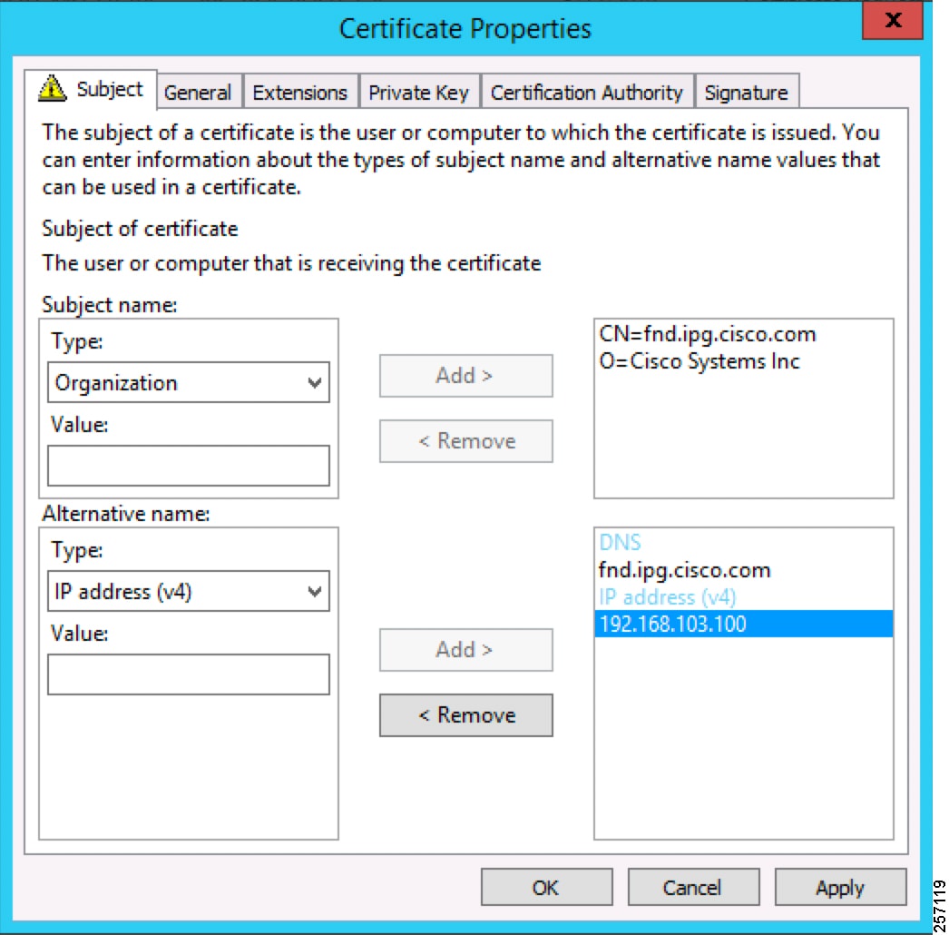
The Subject Name is the Common Name that must be set to the FQDN of the PnP Server.
The Subject Alternative Name must be set to the FQDN of the FND, along with the optional IP address. The Subject Alternative Name is required for PnP to work. The IP address in Figure 38 will be reachable after tunnel is established between IoT gateway and the headend.
The enrolled certificate is exported as PnP-ZTD-FND.pfx and is protected with a password.
Installation of TPS
The bootstrapping procedure in this implementation guide considers the use of TPS as PnP Proxy. For installation of TPS, please refer to Installation of TPS.
Installation of FND
For installation of FND, please refer to the detailed steps covered under the section "Implementing Field Network Director" of the Cisco FAN-Headend Deep Dive Implementation and FAN Use Cases Guide.
Configuration of TPS
This section covers the configuration steps and the final verification steps on the TPS.
TPS Proxy Properties Configuration
TPS Proxy Properties file needs to be configured with the following details:
■![]() inbound-bsproxy-destination: Address to which the bootstrapping requests be forwarded.
inbound-bsproxy-destination: Address to which the bootstrapping requests be forwarded.
■![]() enable-bootstrap-service: Is bootstrapping service enabled/disabled?
enable-bootstrap-service: Is bootstrapping service enabled/disabled?
■![]() bootstrap-proxy-listen-port: Port on which the PnP Proxy must be listening for processing bootstrapping requests (default port is 9125).
bootstrap-proxy-listen-port: Port on which the PnP Proxy must be listening for processing bootstrapping requests (default port is 9125).
Name resolution entries have to be present for FND FQDN in the /etc/hosts file.
Mandatory Verification Checks on TPS Proxy
The verification checks include the following:
■![]() FND FQDN entry in /etc/hosts.
FND FQDN entry in /etc/hosts.
■![]() TPS must have three certificates installed into the cgms_keystore:
TPS must have three certificates installed into the cgms_keystore:
–![]() Certificate signed by Utility PKI for TPS (with private key)
Certificate signed by Utility PKI for TPS (with private key)
–![]() Public Certificate of the Utility PKI CA server
Public Certificate of the Utility PKI CA server
–![]() Public Certificate of the Cisco SUDI CA
Public Certificate of the Cisco SUDI CA
■![]() Hostname consistency with the certificate.
Hostname consistency with the certificate.
■![]() There shouldn't be any unreachable name servers in /etc/resolv.conf.
There shouldn't be any unreachable name servers in /etc/resolv.conf.
■![]() NTP daemon should be running. Time should be synchronized.
NTP daemon should be running. Time should be synchronized.
■![]() Necessary firewall ports must have been opened up, if the firewall/iptables/ip6tables are enabled:
Necessary firewall ports must have been opened up, if the firewall/iptables/ip6tables are enabled:
–![]() TCP Port 9125 to process http communication
TCP Port 9125 to process http communication
–![]() TCP port 9120 to process https communication
TCP port 9120 to process https communication
■![]() FND FQDN entry in /etc/hosts:
FND FQDN entry in /etc/hosts:
TPS must have three certificates installed into the cgms_keystore:
■![]() The certificate entry 'root' represents the Utility PKI CA certificate.
The certificate entry 'root' represents the Utility PKI CA certificate.
■![]() The certificate entry 'sudi' represents the Cisco SUDI CA certificate.
The certificate entry 'sudi' represents the Cisco SUDI CA certificate.
■![]() The certificate entry 'cgms' represents the private certificate of the TPS server signed by the (custom) Utility PKI CA server.
The certificate entry 'cgms' represents the private certificate of the TPS server signed by the (custom) Utility PKI CA server.
Keytool -list -keystore /opt/cgms-tpsproxy/conf/cgms_keystore:
Hostname should match the certificate Common Name/SAN:
No unreachable name servers should exist. Either the name servers should be present and reachable or they should be empty. Any unreachable name server address entry must be taken care or removed under the network interface configuration.
NTP daemon should be running. Time should be synchronized:
Note: The TPS server should be time synchronized. Otherwise, the https communication from the IoT Gateway might not reach the TPS Proxy Application.
Configuration of FND
This section covers the configuration steps and the final verification steps on the FND.
CGMS Properties Configuration
The CGMS Properties file needs to be configured with the following details:
■![]() proxy-bootstrap-ip: Address of the PnP Proxy from which the bootstrapping requests are processed
proxy-bootstrap-ip: Address of the PnP Proxy from which the bootstrapping requests are processed
■![]() enable-bootstrap-service: Enable/Disable the bootstrapping service
enable-bootstrap-service: Enable/Disable the bootstrapping service
■![]() bootstrap-fnd-alias: The trust point alias to be used during bootstrapping of the IoT Gateway
bootstrap-fnd-alias: The trust point alias to be used during bootstrapping of the IoT Gateway
■![]() ca-fingerprint: fingerprint of the 'root' trustpoint
ca-fingerprint: fingerprint of the 'root' trustpoint
Name resolution entries have to be present for TPS FQDN in the /etc/hosts file.
In our lab setup, the proxy-bootstrap-ip is a DMZ IP. In cases where FQDN is globally resolvable, then FQDN can be used instead of IP.
Mandatory Verification Checks on FND
Verification checks include the following:
■![]() TPS FQDN entry in the /etc/hosts file.
TPS FQDN entry in the /etc/hosts file.
■![]() FND must have three certificates installed into the cgms_keystore:
FND must have three certificates installed into the cgms_keystore:
–![]() Certificate signed by Utility PKI for FND (with private key)
Certificate signed by Utility PKI for FND (with private key)
–![]() Public Certificate of the Utility PKI CA server
Public Certificate of the Utility PKI CA server
–![]() Public Certificate of the Cisco SUDI CA
Public Certificate of the Cisco SUDI CA
■![]() Hostname must be consistent with the certificate.
Hostname must be consistent with the certificate.
■![]() No unreachable name servers in /etc/resolv.conf should exist.
No unreachable name servers in /etc/resolv.conf should exist.
■![]() NTP daemon should be running. Time should be synchronized.
NTP daemon should be running. Time should be synchronized.
■![]() Necessary firewall ports must have been opened up if the firewall/iptables/ip6tables are enabled:
Necessary firewall ports must have been opened up if the firewall/iptables/ip6tables are enabled:
–![]() TCP Port 9125 to process http communication
TCP Port 9125 to process http communication
–![]() TCP port 9120 to process https communication
TCP port 9120 to process https communication
TPS/FND FQDN entry in the /etc/hosts file:
FND must have three certificates installed into the cgms_keystore:
■![]() The certificate entry 'root' represents the Utility PKI CA certificate.
The certificate entry 'root' represents the Utility PKI CA certificate.
■![]() The certificate entry 'sudi' represents the Cisco SUDI CA certificate.
The certificate entry 'sudi' represents the Cisco SUDI CA certificate.
■![]() The certificate entry 'cgms' represents the private certificate of the FND server signed by the (custom) Utility PKI CA server.
The certificate entry 'cgms' represents the private certificate of the FND server signed by the (custom) Utility PKI CA server.
Hostname should match the certificate Common Name/SAN:
No unreachable name servers should exist. Either the name servers should be present and reachable or they should be empty. Any unreachable name server address entry must be taken care or removed under the network interface configuration:
NTP daemon should be running. Time should be synchronized:
Note: The FND server should be time synchronized. Otherwise, the https communication from the IoT Gateway might not reach the FND (cgms) application.
Csv File Import on FND GUI
A sample csv file that can be imported into FND for bootstrapping of IoT Gateway is shown below:
Device Bootstrapping
After the above sections have been implemented, the headend is now ready for both provisioning and deployment.
The device bootstrapping is an important process as it eliminates the manual intervention to create and copy the express config to the device.
Device bootstrapping using Cisco PnP Connect has been clearly elucidated in PnP Server Discovery through Cisco PnP Connect and Bootstrapping.
Device Deployment
After the device has been successfully bootstrapped using Cisco PnP Connect, the device is now ready to undergo ZTD. No manual interface is required for the ZTD to begin.
Deployment over IPv4 Cellular Network with NAT, elucidates the ZTD process that would begin as soon as bootstrapping using Cisco PnP Connect is complete.
IoT Gateway Validation Matrix
Table 12 captures the Bootstrapping and ZTD validation matrix across the various platform types, supported as IoT Gateways.
From Table 12, Platform IR1101 has been validated for:
■![]() Bootstrapping over IPv6 Ethernet
Bootstrapping over IPv6 Ethernet
Similarly, Platform IR1101 has been validated for:
■![]() Bootstrapping over IPv4 Ethernet
Bootstrapping over IPv4 Ethernet
■![]() ZTD over IPv4 Ethernet/Cellular
ZTD over IPv4 Ethernet/Cellular
Similarly, Platform IR807 has been validated for:
■![]() Bootstrapping over IPv4 Ethernet
Bootstrapping over IPv4 Ethernet
■![]() ZTD over IPv4 Ethernet/Cellular
ZTD over IPv4 Ethernet/Cellular
Similarly, platforms CGR1120 and CGR1240 have been validated for:
■![]() Bootstrapping over IPv4 Ethernet
Bootstrapping over IPv4 Ethernet
■![]() ZTD over IPv4 Ethernet/Cellular
ZTD over IPv4 Ethernet/Cellular
All other platform types have been validated for:
■![]() Bootstrapping over IPv4 Ethernet
Bootstrapping over IPv4 Ethernet
■![]() ZTD over IPv4 Ethernet network
ZTD over IPv4 Ethernet network
With this, the Cellular DA Gateways or Cisco Field Area Routers could be on boarded and registered with FND, enabling further remote management and monitoring from FND.
The next section discusses in detail the implementation steps required to onboard the Cisco Resilient Mesh Endpoints like the Cisco IR510 WPAN Industrial Router, to serve the functionality of the DA Gateway.
Zero Touch Enrollment of Cisco Resilient Mesh Endpoints
This chapter includes the following major topics:
■![]() Secure Onboarding of Mesh Nodes into CR Mesh
Secure Onboarding of Mesh Nodes into CR Mesh
■![]() MAP-T Infrastructure in DA Feeder Automation
MAP-T Infrastructure in DA Feeder Automation
■![]() Configuration Options from FND
Configuration Options from FND
■![]() Routing Advertisements from FAR to HER
Routing Advertisements from FAR to HER
Staging
This section describes the implementation steps needed to bring up the CR Mesh using IR510 DA Gateways (also referred to as FDs). The IR510 connects to the CGR (also referred to as the FAR) via the Connected Grid Module (CGM) WPAN-OFDM-FCC module that needs to be installed within the FAR.
Note: For information on setting up the WPAN module, please refer to the Connected Grid Module (CGM) WPAN-OFDM-FCC Module - Cisco IOS at following URL:
■![]() https://www.cisco.com/c/en/us/td/docs/routers/connectedgrid/modules/cgm_wpan_ofdm/cgm_wpan_ofdm.html#pgfId-157681
https://www.cisco.com/c/en/us/td/docs/routers/connectedgrid/modules/cgm_wpan_ofdm/cgm_wpan_ofdm.html#pgfId-157681
Table 13 lists the basic components along with their software versions needed to bring up the CR Mesh topology depicted in Figure 1.
Certificate Creation
The prerequisites for deploying a CR Mesh include obtaining all the necessary ECC certificates from the CA server and configuring the AAA RADIUS server to authenticate the IR510 using a certificate-based authentication method. The FAR facilitates dot1x authentication between the IR510 and AAA server, thereby acting as the dot1x authenticator. The ECC certificate mentioned earlier is part of the configuration binary file (.bin) used to program the IR510 node. The ECC certificates and procedures for generating the config file for IR510 are described in further sections.
Note: While the FD need ECC CA certificates for zero touch enrollment, FAR use RSA type certificate for ZDT.
The following certificates need to be obtained from the ECC CA to program an IR510:
■![]() The X.509 certificate of the IR510 node in PKCS#12 format (.pfx) contains its private key and is used to program the node.
The X.509 certificate of the IR510 node in PKCS#12 format (.pfx) contains its private key and is used to program the node.
■![]() The DER-encoded X.509 certificate (.cer) of the IR510 node without the private key is used to enroll the node with the Active Directory.
The DER-encoded X.509 certificate (.cer) of the IR510 node without the private key is used to enroll the node with the Active Directory.
■![]() The DER-encoded X.509 certificate (.cer) of the ECC CA server is also used for programming the IR510 node.
The DER-encoded X.509 certificate (.cer) of the ECC CA server is also used for programming the IR510 node.
■![]() The CSMP certificate downloaded from the IoT FND in binary format (.cer) to validate node CSMP registration with IoT FND.
The CSMP certificate downloaded from the IoT FND in binary format (.cer) to validate node CSMP registration with IoT FND.
For details on setting up and configuring the ECC CA and AAA server and on obtaining all of the above certificates, please refer to Secure Onboarding of Mesh Nodes into CR Mesh.
The following section describes the process for generating a configuration binary file (.bin) used to program the IR510 node.
Bin File Creation
The configuration file for the IR510 nodes is prepared in binary format using the Configuration Writer utility (cfgwriter).
Note: To obtain the cfgwriter utility discussed below, please check with your Account team or Sales representative.
cfgwriter is a java-based utility that takes as input an XML file with the node configuration information and produces a binary (.bin) memory file. This utility may be executed on any host platform with Java Run Time Environment installed. In this deployment, a Windows 10 machine with Java pre-installed was used to host the cfgwriter utility. The node configuration information, among other items, includes the SSID of the WPAN it must join and the security certificates. The schema of the XML configuration file and the corresponding documentation are packaged with the cfgwriter utility as a ZIP file.
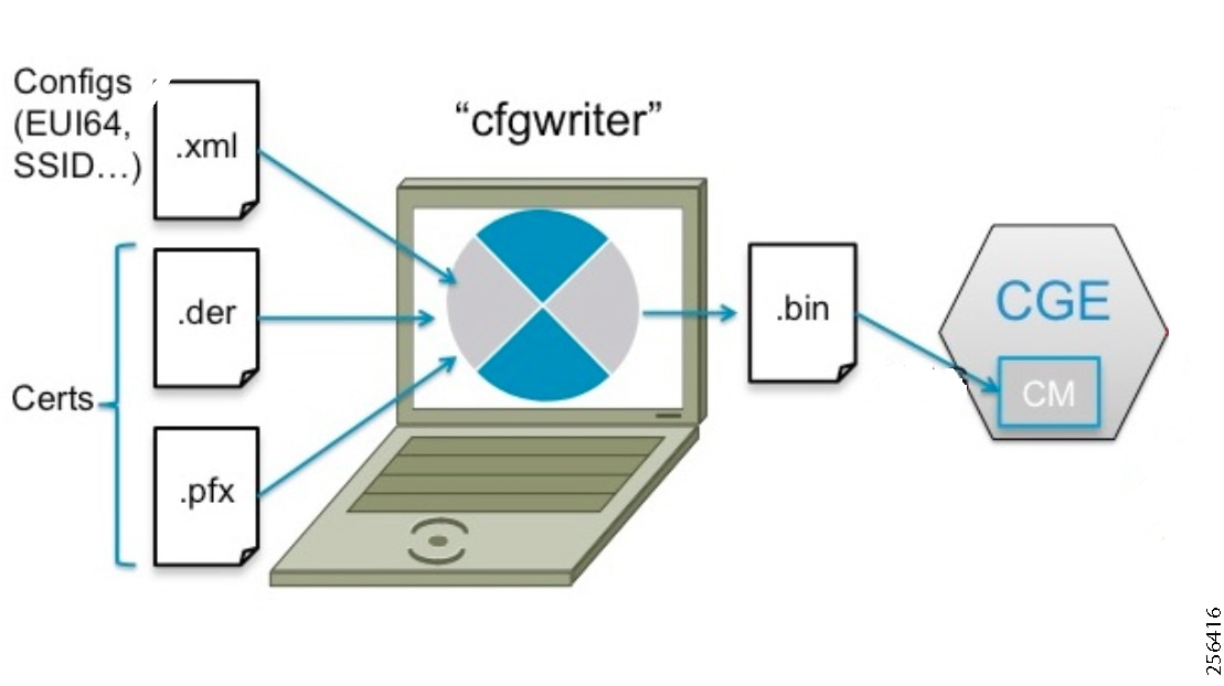
The following XML file is used in this deployment to program the IR510 node:
Note: In the above schema, phy mode 149 refers to OFDM modulation with a data rate of 800kb/s.
The cfgwriter utility converts the input XML file into a binary format (.bin) output. Successful execution of the cfgwriter utility with the XML file and necessary certificates as input will return a '0' numeric code to Standard Output (stdout).
From the command prompt on a Windows PC, navigate to the folder where the cfgwriter utility and all the necessary certificates described in Table 14 are placed.
The following is the command syntax used to generate the config (.bin) file needed to program the IR510 node:
java -jar cfgwriter-6.0.20.jar -x <IR510.pfx> -p <password> -ca <CAcert.cer> -w <config.xml> --nmscert <csmpcert.cer> <outputfile.bin>
The command line parameters used in the above command are explained in Table 14:
Figure 40 shows a sample command issued to generate the.bin file needed for IR510 programming.

Bin File Programming
The binary configuration file (.bin) prepared in the previous step, along with the correct firmware, is programmed into the IR510 node using another utility known as HostOne tool (fwubl). This tool is also placed on the same Windows machine where the cfgwriter utility was placed.
Note: To obtain the HostOne (fwubl) tool discussed below, please check with your Account team or Sales representative.
From the same Windows machine, connect to the IR510 console port using an USB to serial converter connected through a Cisco RJ45 to DB9 (female) blue serial console cable. From the command prompt on Windows PC, navigate to the folder where the fwubl tool is placed along with the firmware image and config bin files of the IR510.
Note: Do not power on the IR510 unit without any attenuators, antenna, or RF cabling in place. It is highly recommended to keep the RF port on the node always connected; don't leave it to transmit in free air since without the right connector/RF cables, the radio has a high likelihood of becoming damaged.
Once the node is powered on, issue the following command to verify that the node is in bootloader mode first. If it isn't, power cycle the node and check again as it would re-enter into the bootloader mode.
fwubl_win732bit_1.0.5.exe com<port>
The above command output would show the current bootloader version on the node besides few other parameters. Figure 41 shows the sample output of an IR510 unit initially in bootloader mode.
Figure 41 IR510 in Bootloader State
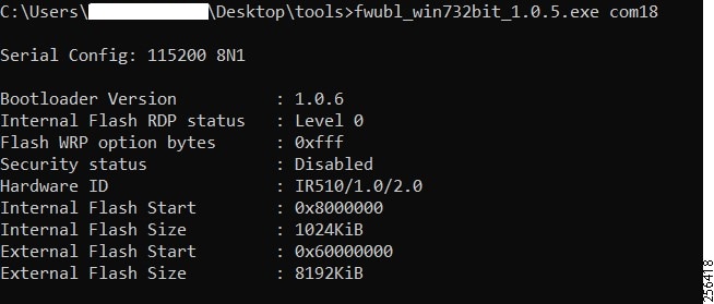
The next step is to program the firmware version on the IR510 into the memory location specified in the following command:
fwubl_win732bit_1.0.5.exe -w <IR510 firmware.bin> -a 0x8020000 com<port>
Figure 42 shows the sample output of firmware push issued to an IR510 unit.
Figure 42 Firmware Push on IR510
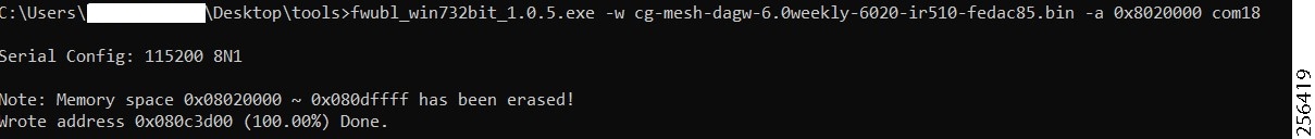
The next step is to program the config.bin file generated for the IR510 into the memory location specified in the following command:
fwubl_win732bit_1.0.5.exe -w <IR510 config.bin> -a 0x80E0000 com<port>
Figure 43 shows the sample output of config bin push issued to an IR510 unit:
Figure 43 Config Bin Push on IR510
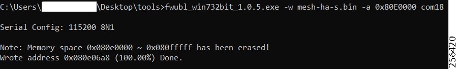
The final step is to enable CR Mesh on IR510 by bringing it out of bootloader mode by issuing the following command:
fwubl_win732bit_1.0.5.exe -g 0x8020000 com<port>
Figure 44 shows the sample output to run CG-mesh software on the IR510 unit.
Figure 44 CR Mesh enabled on IR510
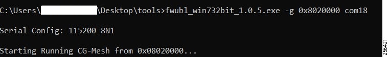
Secure Onboarding of Mesh Nodes into CR Mesh
Staging provided details on how to set up an IR510 node to securely join the mesh network. This section discusses the components needed to enable secure onboarding of IR510 nodes into the mesh network.
CR Mesh Endpoint - Authentication Call Flow
The FAR router provides security services such as 802.1x port-based authentication, encryption, and routing to provide a secure connection for the mesh endpoint all the way to the control center. IEEE 802.1x using X.509 certificates is the process used to securely authenticate a mesh node before allowing it to join the PAN or to even send packets into the network.
For details regarding authentication call flow using dot1x, please refer to figure "IEEE 802.1x Device Authentication" under the section "Network Security" in the Design Guide.
CR Mesh Endpoint Onboarding - Associated Touchpoints in the Headend
Table 15 lists the associated touchpoints that should be set up and configured as a prerequisite step before enabling secure onboarding process of mesh nodes.
Issuing ECC type certificates for mesh end points and AAA server |
"ECC Type CA Server Configuration" at the following URL: ■ |
|
Setting up AAA RADIUS server using Microsoft Network Policy Server (NPS) |
"Implementing AAA Server with Microsoft Network Policy Server" at the following URL: ■ |
|
"Configuring Network Policy Server for Smart Meter Authentication" at the following URL: ■ |
||
Enrolling mesh endpoints IR510 in AD using public certificate |
"Configuring Smart Meters in Active Directory" at the following URL: ■ |
|
Obtaining CSMP certificate from IoT FND to program mesh nodes |
Browse to point 8 referring to the "Certificates for CSMP tab" in "Configuring a Custom CA for SSM" at the following URL: ■ Click the radio button showing the binary option and download the. pem binary certificate (manually change extension to.cer for programming into the IR510). |
Associated CGR Configurations for Onboarding of the Cisco WPAN Industrial Router (IR510)
Note: The following configurations are for reference purposes only. They would be dynamically provisioned by the FND as part of Zero Touch Deployment (ZTD) of CGR.
WPAN Configuration on CGR to Enable Secure Mesh
The following is the sample configuration of a CGR1240 for the WPAN interface. Please note that the SSID configured on the WPAN interface below matches what was configured in the IR510 XML schema shown in an earlier section.
AAA RADIUS Client Configuration on CGR
The following is the RADIUS client configuration needed on CGR1240 for enabling dot1x authentication of the mesh endpoint with the AAA server:
Note: The secret key above configured on the CGR must match the secret key configured on NPS when adding CGR as a radius client.
Mesh Key Configuration on CGR
As part of ZTD, the FAR is provisioned with a mesh key pushed from FND that is used to provide link layer encryption for the communication between the IR510 and the FAR.
The following command is used to verify if the key is indeed present on the CGR:
DHCPv6 Server Configuration on CGR for Address Allocation
The CR Mesh nodes need to be assigned an IPv6 address for reachability from the CGR as well as from the control center. For this purpose, a local IPv6 DHCP pool is configured on the CGR as shown below. However, a central DHCP server option, if available is recommended.
From the above mesh prefix, the first address 2001:DB8:ABCD:1::1/64 is assigned to the CGR WPAN interface while the mesh nodes are allocated an IPv6 address from the remaining pool. The sub-option 1 address specifies the IPv6 address of the IoT FND to the mesh nodes.
Note: Please refer to Appendix E: HER and CGR Configurations for the complete configuration of CGR tested to bring up the CR Mesh.
MAP-T Infrastructure in DA Feeder Automation
Basic Overview of MAP-T
MAP-T refers to address and port mapping using a translation mechanism and is used to provide connectivity to IPv4 hosts over IPv6 domains by performing double translation (IPv4 to IPv6 and vice versa) on customer edge (CE) devices and border routers.
A MAP-T domain is comprised of one or more MAP CE devices (IR510) and a border relay router (HER), all of which are connected to the same IPv6 network.
For a MAP-T domain to be operational, mapping rules known as basic mapping rules (BMR) and a default mapping rule (DMR) must be configured. While BMR is configured for the MAP IPv6 source address prefix, DMR is used to map IPv4 information to IPv6 addresses for destinations outside a MAP-T domain. Some port parameters like share-ratio and start-port are also configured for the MAP-T BMR whereas EA bits refer to the IPv4 embedded address bits within the MAP-T IPv6 address identifier of the MAP-T CPE.
For more details on MAP-T, please refer to “Mapping of Address and Port Using Translation” at the following URL:
■![]() https://www.cisco.com/c/en/us/td/docs/ios-xml/ios/ipaddr_nat/configuration/15-mt/nat-15-mt-book/iadnat-mapt.pdf
https://www.cisco.com/c/en/us/td/docs/ios-xml/ios/ipaddr_nat/configuration/15-mt/nat-15-mt-book/iadnat-mapt.pdf
Packet Flow in MAP-T network:
The following is the logical packet flow between a SCADA client and the SCADA Master:
SCADA Client --> IPv4 --> IR510 --> IPv6 --> CGR --> IPv6 --> HER --> IPv4 --> SCADA Master
An actual sample packet flow, including MAP-T parameters like BMR and DMR used in this implementation, is illustrated in Figure 45.
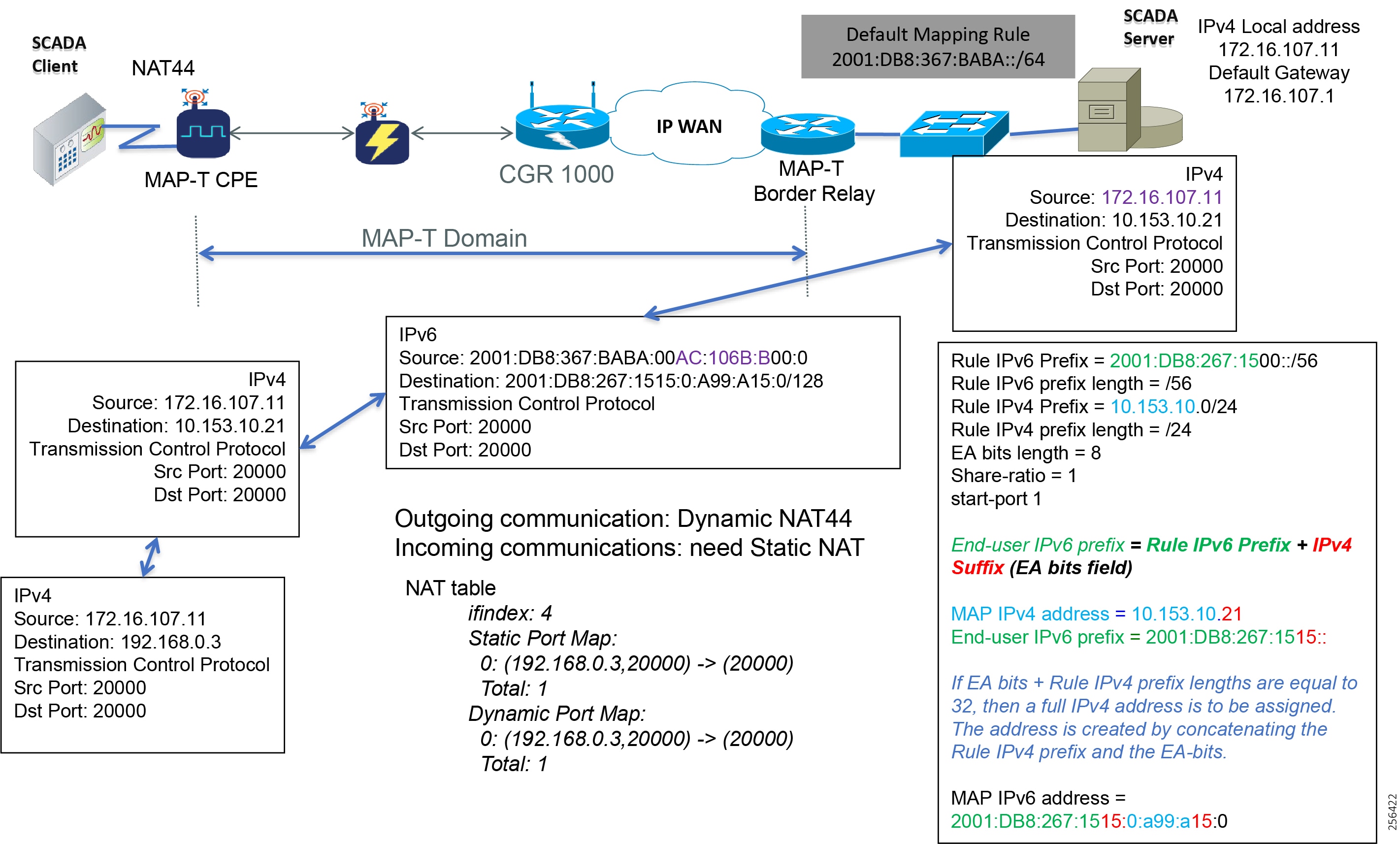
While configuring MAP-T, the DMR prefix, the IPv6 user prefix, and the IPv6 prefix plus the embedded address (EA) bits must be less than or equal to 64 bits.
Note: MAP-T parameters like the BMR IPv6 prefix and associated prefix length unique to each node are configured as part of the.csv file uploaded to IoT FND whereas the DMR IPv6 and the BMR IPv4 prefixes and their associated lengths along with EA bit length are configured via the configuration template in IoT FND which is later applied to the nodes, as shown later in Configuration Options from FND.
MAP-T Points in the Network
IR510 - MAP-T CE
A MAP-T CE device connects a user's private IPv4 address and the native IPv6 network to the IPv6-only MAP-T domain by first doing a NAT44 translation from the private to public (inside to outside) address within the v4 domain and then subsequently doing a v4 to v6 translation.
MAP-T BMR Prefix Selection for IR510.csv
The BMR prefix is used by the MAP-T CE to configure itself with an IPv4 address, an IPv4 prefix from an IPv6 prefix. As shown in Figure 45, the Rule IPv6 prefix represents the BMR IPv6 prefix used in the MAP-T network. As such, the BMR IPv6 prefix of 2001:DB8:267:1515::/56 corresponds to the MAP-T IPv4 address of 10.153.10.21 of an IR510 node.
HER - MAP-T Border Relay Router
The following configuration is needed on the HER to enable MAP-T border relay functionality:
Additionally, the CLI command nat64 enable needs to be enabled as shown below on the HER interfaces participating in the MAP-T translations (such as the interface where the SCADA Master connects and the tunnel interface towards CGR).
The HER interface connecting to the control center side where SCADA Master resides is IPv4 based whereas the virtual-template interface of the HER connecting to the CGR on the WAN side is IPv6 based, as shown logically below:
CGR --> IPv6 --> (VTI) HER (Gig port) --> IPv4 --> SCADA Master
Enabling nat64 on the SCADA Master-facing interface of the HER below:
Enabling nat64 on the FAR-facing Virtual-Template interface of HER below:
Note: For the complete running configuration of the HER, please refer to Appendix E: HER and CGR Configurations.
Configuration Options from FND
Csv File Import at FND
The following template can be used to add mesh endpoints to the FND database.
eid,deviceType,function,enduseripv6prefix,bmripv6prefixlen
The above fields are explained in Table 16:
A Unique Element identifier to identify the device in log messages as well as in the IoT FND GUI. |
|
Used to identify the functionality of IR510 (i.e., DA Gateway). |
|
The following are the contents of a sample csv file used in this implementation:
1.![]() To upload the CSV file into IoT FND, navigate to the GUI.
To upload the CSV file into IoT FND, navigate to the GUI.
2.![]() From Inventory tab > Devices > Field Devices > Add Devices, click Browse to upload the file as shown in Figure 46
From Inventory tab > Devices > Field Devices > Add Devices, click Browse to upload the file as shown in Figure 46
Figure 46 CSV File Upload to IoT FND
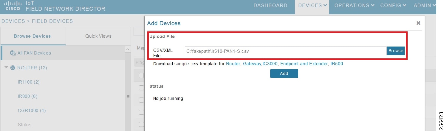
Once added, the devices will initially be in Unheard state. Once mesh nodes start registering with the FND, their device status turns green as shown in Figure 47.
Figure 47 Mesh Endpoint Status in FND
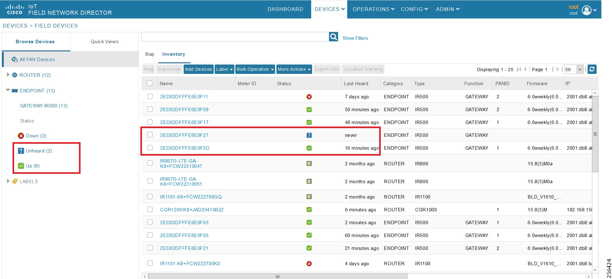
The nodes must register successfully with IoT FND before other settings like MAP-T, NAT44, and other serial configuration profiles be properly pushed/applied to the nodes. However, if those settings are pre-linked via the default profiles, the configuration would be automatically pushed to the nodes upon device registration.
Creation of MAP-T Group
1.![]() To configure the MAP-T settings in FND, navigate to Config > Device Configuration.
To configure the MAP-T settings in FND, navigate to Config > Device Configuration.
2.![]() Under Config Profiles and click the Add Profile icon (+).
Under Config Profiles and click the Add Profile icon (+).
3.![]() Create a new MAP-T profile with the correct settings for BMR and DMR rules, as shown in Figure 48.
Create a new MAP-T profile with the correct settings for BMR and DMR rules, as shown in Figure 48.
Figure 48 Creating a MAP-T Profile
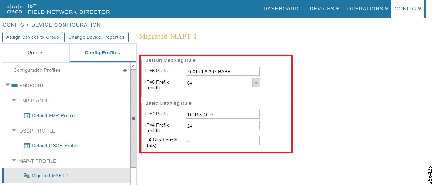
Creation of NAT44 Group on FND
1.![]() To configure the NAT44 settings for mesh endpoints in FND, navigate to Config Profiles > Config > Device Configuration.
To configure the NAT44 settings for mesh endpoints in FND, navigate to Config Profiles > Config > Device Configuration.
2.![]() Click the Add Profile icon (+).
Click the Add Profile icon (+).
3.![]() Create a new NAT44 profile with the correct Internal IPv4 address, internal, and external ports, as shown in Figure 49.
Create a new NAT44 profile with the correct Internal IPv4 address, internal, and external ports, as shown in Figure 49.
Figure 49 Creating a NAT44 Profile
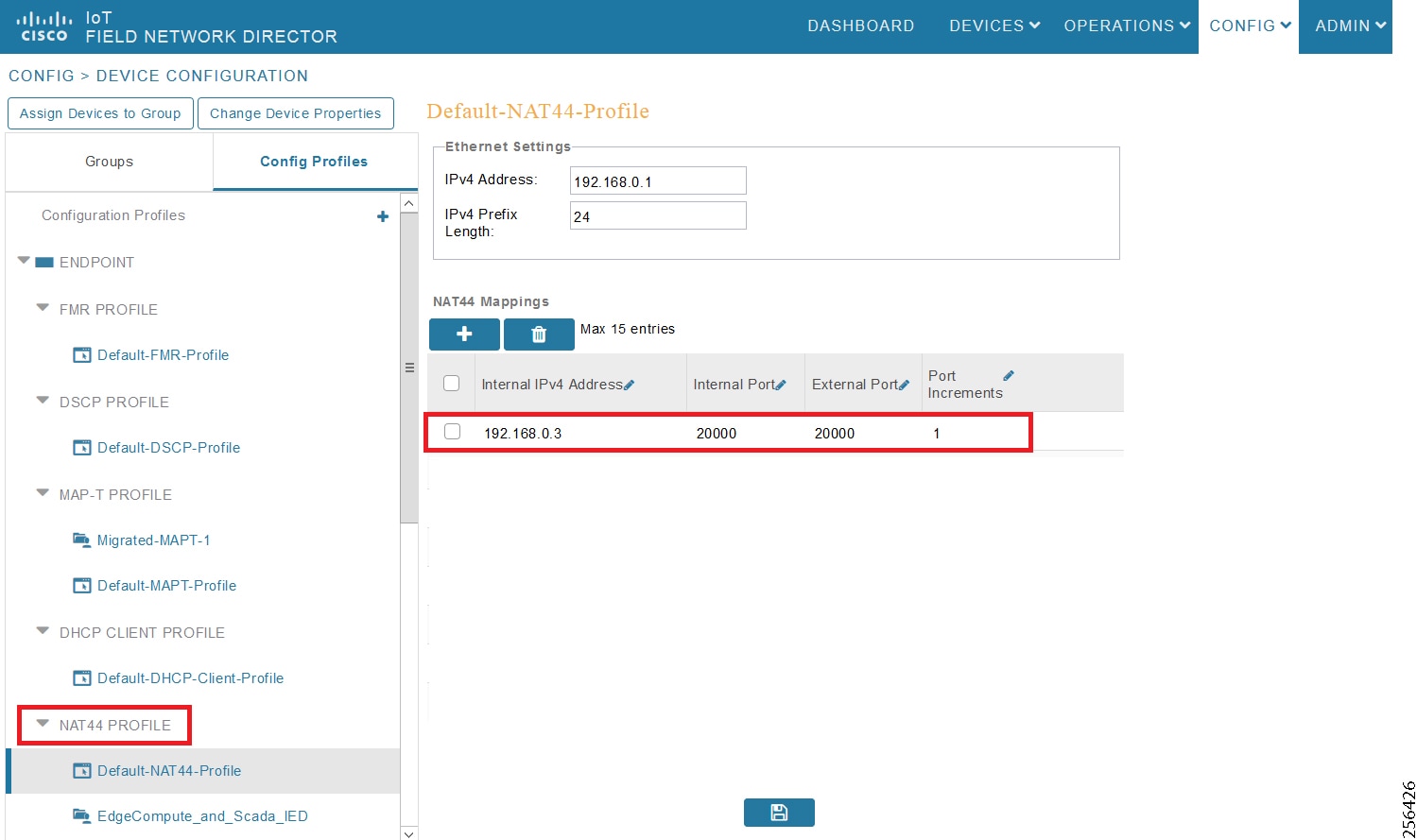
In Figure 49, the IPv4 address and prefix length of the IR510 are specified under Ethernet Settings.
The Internal IPv4 address refers to the internal address of the NAT44-configured device like the SCADA client, which is connected behind IR510. The internal port refers to the internal port number on which the SCADA client would be listening. The external port refers to the external port number of the SCADA client accessed by devices from outside MAP-T domain.
Note: Since 192.168.0.2 is reserved for the Guest OS inside the IOX portion of the IR510 unit, it is recommended to use a different address such as 192.168.0.3 for the SCADA client and, accordingly, multiple NAT44 mappings like the one shown above could be created for different ports.
Creation of Configuration Group on FND
Initially all the IR510s added to the FND are placed in the Default-IR500 group. Depending on the deployment, some of them can be moved to a newly created configuration group in which the corresponding MAP-T, NAT44 profiles can be selectively applied and a config pushed to these nodes.
1.![]() To create a configuration group, navigate to the Groups tab > Config > Device Configuration.
To create a configuration group, navigate to the Groups tab > Config > Device Configuration.
2.![]() Click the Add Group icon (+).
Click the Add Group icon (+).
3.![]() Then create a new group of type Endpoint as shown in Figure 50.
Then create a new group of type Endpoint as shown in Figure 50.
Figure 50 Creating an Endpoint Configuration Group
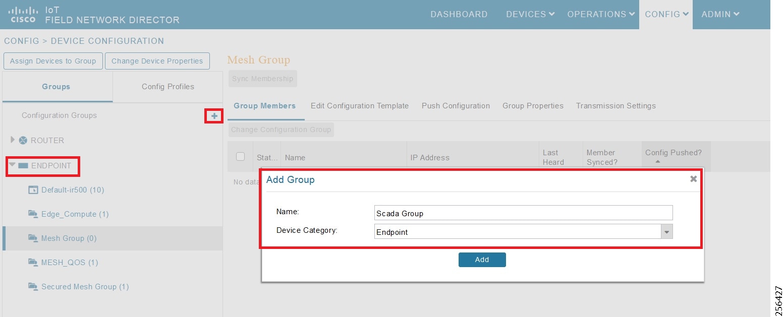
4.![]() Move some of the mesh nodes from the default endpoint group to the newly created group based on the deployment.
Move some of the mesh nodes from the default endpoint group to the newly created group based on the deployment.
5.![]() Navigate to the default endpoint group, select the nodes of interest and click Change Configuration Group.
Navigate to the default endpoint group, select the nodes of interest and click Change Configuration Group.
6.![]() Then select the newly created config group in the drop-down menu as shown in Figure 51.
Then select the newly created config group in the drop-down menu as shown in Figure 51.
Figure 51 Moving IR510 to the New Configuration Group
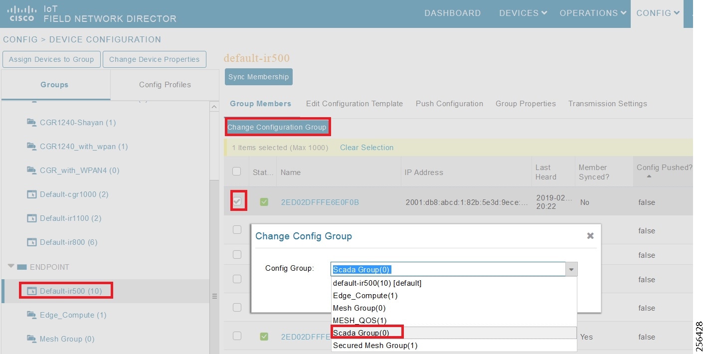
7.![]() Once devices are moved to the newly created configuration group, from the Edit configuration template, select the MAP-T and NAT44 profiles created earlier.
Once devices are moved to the newly created configuration group, from the Edit configuration template, select the MAP-T and NAT44 profiles created earlier.
8.![]() Click Save Changes for these settings to be applied to the devices part of this group, as shown in Figure 52.
Click Save Changes for these settings to be applied to the devices part of this group, as shown in Figure 52.
Figure 52 Editing the Configuration Template
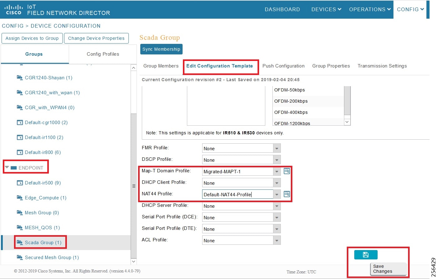
9.![]() Finally, push the configuration to the devices in this group by navigating to the Push Configuration tab, selecting Push Endpoint Configuration.
Finally, push the configuration to the devices in this group by navigating to the Push Configuration tab, selecting Push Endpoint Configuration.
10.![]() Click Start as shown in Figure 53.
Click Start as shown in Figure 53.
Figure 53 Push Configuration Operation
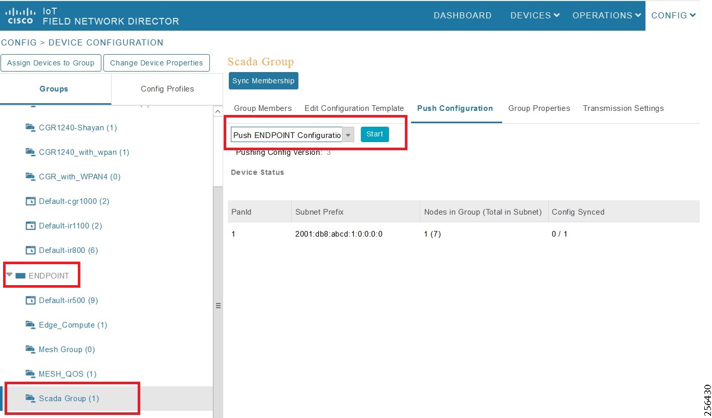
This completes the configuration settings from FND to the mesh node that are needed to operate as a DA gateway.
11.![]() The final step is to verify that all the configuration settings are properly applied to the IR510. Click on the node inside the configuration group and navigate to the Device Info tab, as shown in Figure 54.
The final step is to verify that all the configuration settings are properly applied to the IR510. Click on the node inside the configuration group and navigate to the Device Info tab, as shown in Figure 54.
Figure 54 Verify Configuration Settings on IR510 (1)
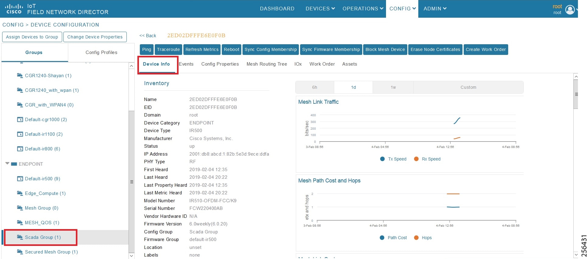
12.![]() On scrolling further down, the MAP-T settings applied to the device can be verified, as shown in Figure 55.
On scrolling further down, the MAP-T settings applied to the device can be verified, as shown in Figure 55.
Figure 55 Verify Configuration Settings on IR510 (2)
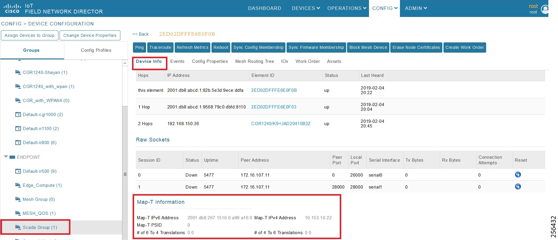
Routing Advertisements from FAR to HER
Note: HER advertises a default route to all the FARs in order to provide connectivity to control center components.
Advertising Summary Route of LoWPAN Prefix
Once the CR Mesh has been formed, the IR510 nodes have reachability only to the FAR. The mesh nodes need a way to communicate all the way to control center components like IoT FND for management purposes. To achieve this, the IPv6 LoWPAN address subnet assigned to the mesh endpoints is advertised to the HER (which has reachability to the control center components) using the IKEv2 prefix injection over the FlexVPN tunnel. Specifically, the mesh prefix is advertised as part of the IPv6 ACL, which is part of the FlexVPN authorization policy as shown below.
Note: The config shown below is for reference purposes only since ZTD takes addresses it.
Advertising MAP-T BMR IPv6 Prefix using Snapshot Routing
As discussed above, besides advertising the Mesh LoWPAN prefix of the IR510 nodes to the HER, even the MAP-T BMR IPv6 prefix of the nodes needs to be reachable from the control center to communicate with the SCADA clients connected to the IR510. To achieve this, the IKEv2 snapshot routing feature is implemented wherein the BMR IPv6 prefix assigned to the mesh endpoints is included in the route map redistributed inside the FlexVPN authorization policy, as shown below.
Note: The config shown below is for reference purposes only since ZTD takes addresses it. Basically, the BMR IPv6 /128 address of the nodes that appear/disappear from the HER routing table are the ones that match the route-map snapshot shown below.
Application Traffic Communication Enablement
This chapter includes the implementation of the following major topics:
■![]() SCADA Control Center Point-to-Point Implementation Scenarios Over Cellular Gateways
SCADA Control Center Point-to-Point Implementation Scenarios Over Cellular Gateways
■![]() SCADA Communication with IP Intelligent Devices
SCADA Communication with IP Intelligent Devices
■![]() SCADA Communication Scenarios over CR Mesh Network (IEEE 802.15.4)
SCADA Communication Scenarios over CR Mesh Network (IEEE 802.15.4)
■![]() SCADA Communication with Serial-based SCADA using Raw Socket UDP
SCADA Communication with Serial-based SCADA using Raw Socket UDP
■![]() SCADA Communication with Serial-based SCADA using Raw Socket TCP
SCADA Communication with Serial-based SCADA using Raw Socket TCP
■![]() Legacy SCADA (Raw Socket TCP Server)
Legacy SCADA (Raw Socket TCP Server)
In order to ensure the proper functioning of substations and related equipment, such as line-mounted switches and CBCs, most utilities use SCADA systems to automate monitoring and control. New sites typically implement a SCADA system to monitor and control substations and related equipment and devices positioned along the feeder. However, older facilities can also benefit by adding a SCADA system or by upgrading an existing SCADA system to take advantage of newer technologies like IP-capable SCADA systems
The Distributed Automation Solution supports the SCADA service models shown in Table 17.
SCADA Control Center Point-to-Point Implementation Scenarios Over Cellular Gateways
In this scenario, the DSO will be hosting SCADA applications (Master) in a Control Center. The SCADA Slave is connected to the DA Gateway via the serial or Ethernet interface. The SCADA Master residing in the DSO Control Center can communicate with the Slave using the DNP3 or DNP3 IP protocol.
Operations that can be executed when the communication protocol is DNP3, DNP3 IP. or DNP3-DNP3 IP translation are as follows:
■![]() Unsolicited Reporting (Slave > Master) - Notification
Unsolicited Reporting (Slave > Master) - Notification
The operations have been executed using a SCADA simulator known as the Distributed Test Manager (DTM), which has the capability of simulating both the Master and the Slave devices.
■![]() If the endpoint is connected to the DA Gateway via the Ethernet port, then it is pure IP traffic. The IP address of the endpoint (i.e., IED) can be NAT'd so that the same subnet between the IED and the Ethernet interface of the DA Gateway can be re-used. This approach will ease the deployment.
If the endpoint is connected to the DA Gateway via the Ethernet port, then it is pure IP traffic. The IP address of the endpoint (i.e., IED) can be NAT'd so that the same subnet between the IED and the Ethernet interface of the DA Gateway can be re-used. This approach will ease the deployment.
■![]() If the endpoint is connected using asynchronous serial (RS-232 or RS-485), then the DNP3 could be tunneled to the control center using Raw Socket, and the SCADA Master would consume as DNP3 or DNP3 to be converted to DNP3 IP at the gateway and the SCADA Master would consume as DNP3/IP.
If the endpoint is connected using asynchronous serial (RS-232 or RS-485), then the DNP3 could be tunneled to the control center using Raw Socket, and the SCADA Master would consume as DNP3 or DNP3 to be converted to DNP3 IP at the gateway and the SCADA Master would consume as DNP3/IP.
This document focuses on SCADA protocols such as the DNP3, DNP3 IP, and DNP3-DNP3 IP translation protocols widely used in the U.S. Region with a Control Center.
Figure 56 Feeder Automation Lab Topology
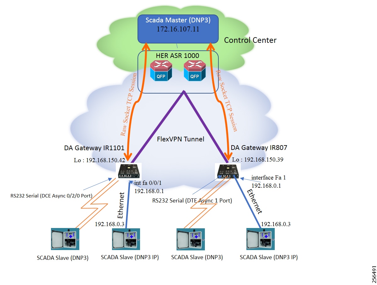
IR1101 and IR807 are implemented as Cellular DA Gateways. ASR 1000s implemented in clustering mode act as a HER, which terminates FlexVPN tunnels from DA Gateways.
The following sections focus upon:
1.![]() SCADA Communication with IP intelligent devices
SCADA Communication with IP intelligent devices
SCADA Communication with IP Intelligent Devices
Protocols Validated
Flow Diagram
Figure 57 DNP3 IP Control Flow

As shown in Figure 57, the SCADA Master DTM can perform a read and write operation to a remote Slave via the DA Gateway. The Slave can send the Unsolicited Reporting to the SCADA Master via the DA Gateway over the IP network.
As per the topology, the interface connected to SCADA Slave has the following configuration. This configuration is only for reference purpose only since ZTD of Cellular gateways will address it. Please refer to Appendix D: SCADA ICT Enablement Profiles.
IR807 DA Gateway Configuration
IR1101 DA Gateway Configuration
SCADA Master Configuration
As per the topology, the SCADA Master is residing in the Control Center. The following configuration must be required for the SCADA Master to communicate with SCADA Slave.
1.![]() Open the SCADA Master Application and add a new DNP3 Master.
Open the SCADA Master Application and add a new DNP3 Master.
2.![]() From the Channel tab, configure the SCADA Master, as per Figure 58.
From the Channel tab, configure the SCADA Master, as per Figure 58.
3.![]() SCADA Master, in this case, is configured as a TCP Client interacting with the SCADA Slave, which is configured to act as TCP Server.
SCADA Master, in this case, is configured as a TCP Client interacting with the SCADA Slave, which is configured to act as TCP Server.
4.![]() Populate the remote address field with the Loopback IP of the Cellular gateway.
Populate the remote address field with the Loopback IP of the Cellular gateway.
5.![]() Populate the port with 20000, which is the port used in the Cisco IOS configuration.
Populate the port with 20000, which is the port used in the Cisco IOS configuration.
Figure 58 SCADA Master Configuration
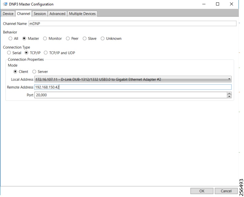
SCADA Slave Configuration
As per the topology, the SCADA Slave resides in the field area. The following configuration must be required for the SCADA Slave to communicate with the SCADA Master.
1.![]() Open the SCADA Slave Application and add a new DNP3 Slave.
Open the SCADA Slave Application and add a new DNP3 Slave.
2.![]() From the Channel tab, configure the SCADA Master, as per Figure 59.
From the Channel tab, configure the SCADA Master, as per Figure 59.
3.![]() Populate the remote address field with SCADA Master IP.
Populate the remote address field with SCADA Master IP.
4.![]() Populate the port with 20000, which is the port used in SCADA Master.
Populate the port with 20000, which is the port used in SCADA Master.
Figure 59 SCADA Slave Configuration
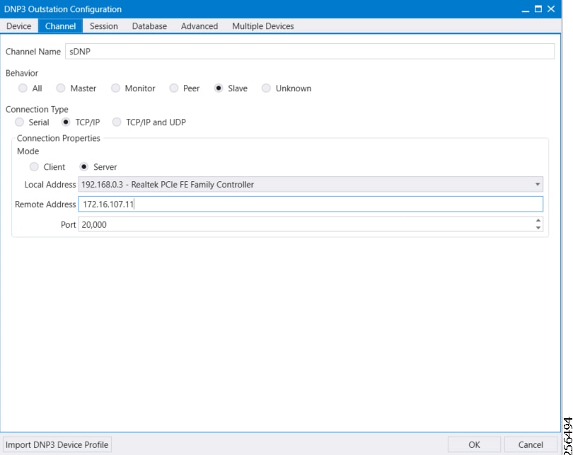
SCADA Operations
The Master and the Slave can communicate via Poll, Control, and Unsolicited Reporting. Poll and Control operations are initiated from the Master. Unsolicited Reporting is sent to the Master from the Slave. Figure 60 and Figure 61 show the Poll operation from the SCADA Master. Similarly, Control and Unsolicited Reporting can be seen on the Master Analyzer logs.
The Poll operation is performed by the Master. The Master can execute a general Poll in which all the register values are read and sent to the Master. In Figure 60 and Figure 61, we see a general Poll executed on the Master side. As Figure 60 shows, the Master Analyzer is initially empty.
Figure 60 Master Analyzer Logs before Poll Operation

However, when the General Interrogation command is executed, the values of all the registers are displayed on the Master Analyzer, as shown in Figure 61.
Figure 61 Master Analyzer Logs after Poll Operation

The Control operation basically sends the control command from the SCADA Master to the SCADA Slave in order to control the operation of end devices. The control command can be executed and the results can be seen on the analyzer. The value of Control Relay Output is changed and is notified to the Master. Figure 62 shows control relay output status before sending the control command to the Slave.
Figure 62 Slave Register before Control Operation
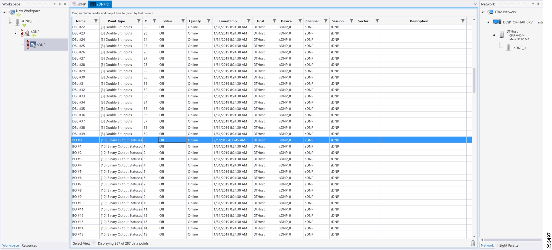
Figure 63 shows how SCADA Master sends the control command.
Figure 63 Master Control Operation

Figure 64 show the Control Command and Control Relay Output status changed on the SCADA Master.
Figure 64 Slave Register after Control Operation
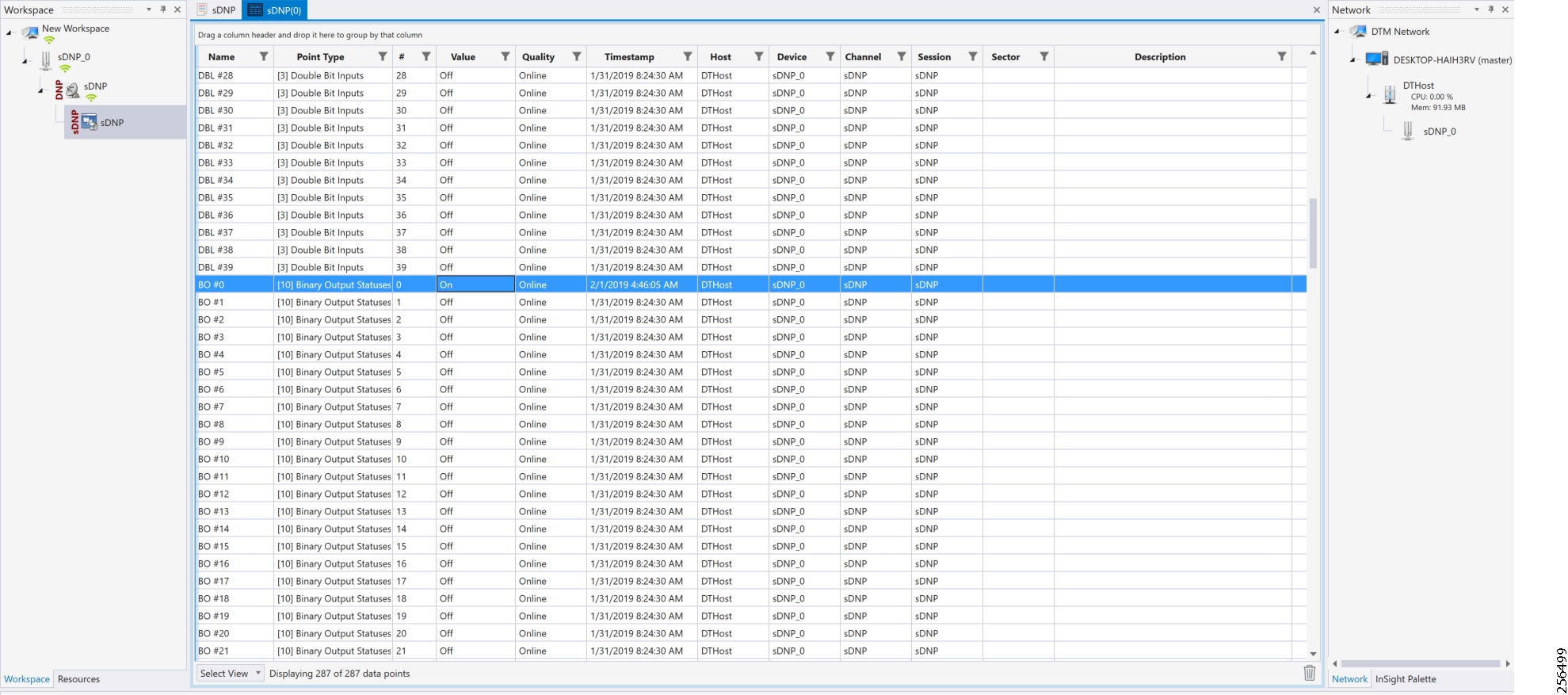
Unsolicited Reporting is initiated by the Slave, which is connected to the DA Gateway. Changes to the value of the Slave register are notified to the SCADA Master. This notification can be seen on the Master Analyzer. Figure 65 shows the SCADA Master Analyzer before any unsolicited reporting.

Figure 66 shows that the binary input of the Slave is going to change. Initially the value of binary input is OFF.

Figure 67 shows that the binary input of the Slave is changed from OFF to ON.
Figure 67 Change in Slave Register Value
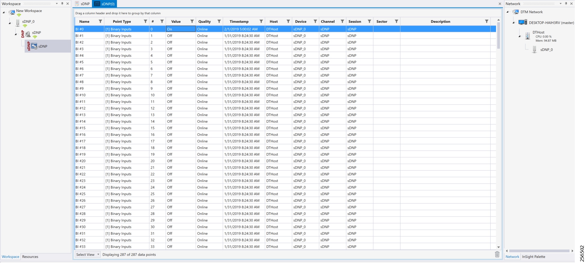
Figure 68 show the Unsolicited Reporting on the analyzer. The value of Binary Inputs is changed and the same is notified to the Master.
Figure 68 Master Analyzer after Change in Register Value

Legacy SCADA (Raw Socket TCP)
Protocols Validated
Flow Diagram
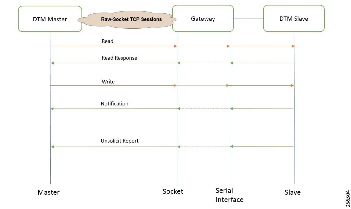
As shown in Figure 69, the DTM Master can read and write the Slave via the DA Gateway using TCP Raw Socket. In addition, the Slave can send the Unsolicited Reporting to the Master via the DA Gateway using TCP Raw Socket. For more details about Raw Socket, refer to the Distribution Automation - Feeder Automation Design Guide.
IR807 DA Gateway Raw Socket Configuration
As per the topology, the interface connected to SCADA Slave has the following configuration:
IR1101 DA Gateway Raw Socket Configuration
As per the topology, the interface connected to SCADA Slave has the following configuration:
SCADA Master Configuration
As per the topology, the SCADA Master is residing in the Control Center. The following configuration is required for the SCADA Master to communicate with SCADA Slave. In this implementation, we used the SCADA DTMW simulator instead of a real SCADA device.
1.![]() Open the SCADA Master Application and click Add a new DNP3 Master.
Open the SCADA Master Application and click Add a new DNP3 Master.
2.![]() From the Channel tab, configure the SCADA Master as per Figure 70.
From the Channel tab, configure the SCADA Master as per Figure 70.
3.![]() On the SCADA Master, select the appropriate serial port, baud rate, data bits, stop bits, and parity matching for your device configuration.
On the SCADA Master, select the appropriate serial port, baud rate, data bits, stop bits, and parity matching for your device configuration.
Figure 70 Master Configuration
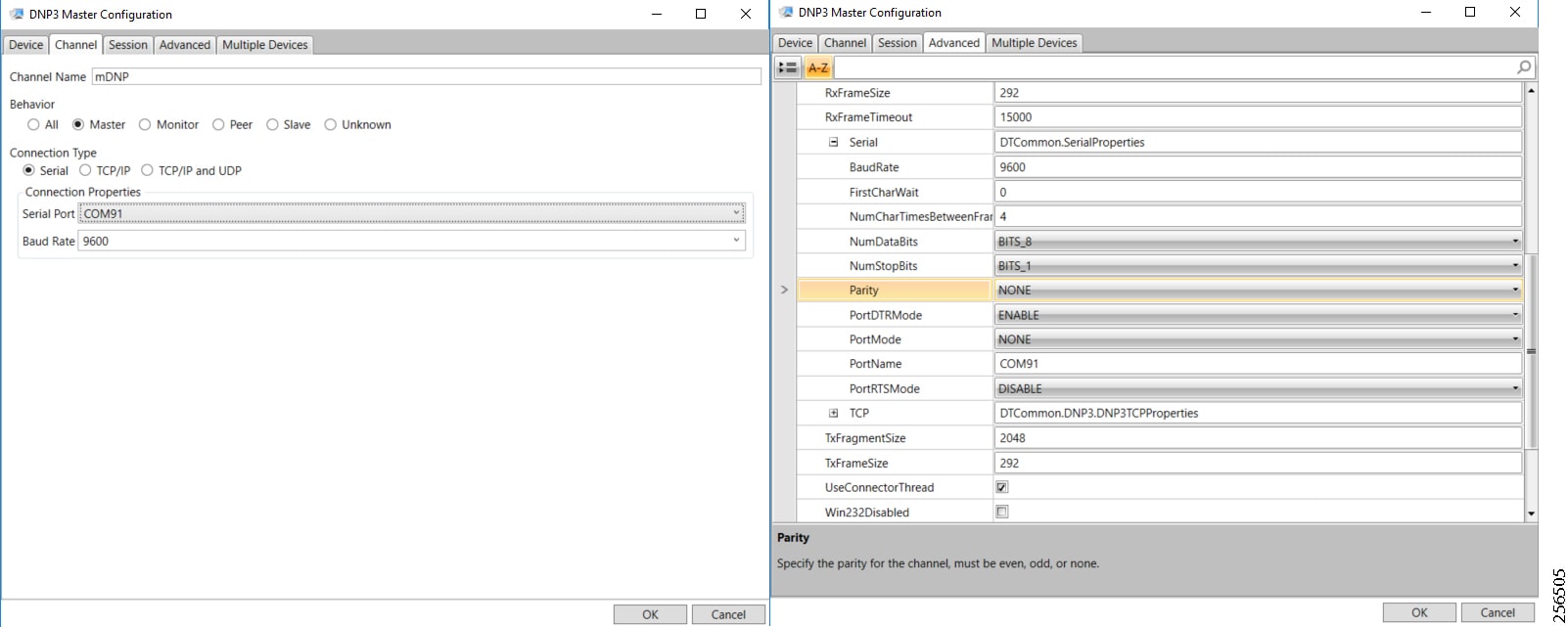
SCADA Slave Configuration
As per the topology, the SCADA Slave is residing in the field area. The following configuration must be required for the SCADA Slave to communicate with the SCADA Master. In this implementation, we used the SCADA DTMW simulator instead of a real SCADA device.
1.![]() Open the SCADA Slave Application and click Add a new DNP3 Slave.
Open the SCADA Slave Application and click Add a new DNP3 Slave.
2.![]() From the Channel tab, configure the SCADA Master as per Figure 71.
From the Channel tab, configure the SCADA Master as per Figure 71.
3.![]() On the SCADA Slave, select the appropriate serial port, baud rate, data bits, stop bits and parity matching for your device configuration.
On the SCADA Slave, select the appropriate serial port, baud rate, data bits, stop bits and parity matching for your device configuration.
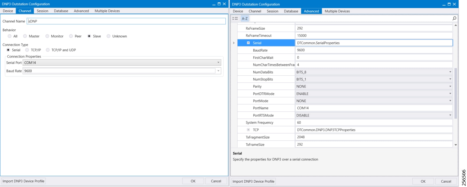
SCADA Operations
The Master and the Slave can communicate via the network. Poll and Control operations are initiated from the Master. Unsolicited Reporting is sent to the Master from the Slave. Figure 72 and Figure 73 show the Poll operation from the SCADA Master. Similarly, Control and Unsolicited Reporting can also be seen on the Master Analyzer logs.
The Poll operation is performed by the Master, which can execute a general Poll in which all the register values are read and sent to the Master. In Figure 72 and Figure 73, we see a general Poll executed on the Master side. As Figure 72 shows, the Master Analyzer is initially empty.
Figure 72 Master Analyzer Logs before Poll Operation
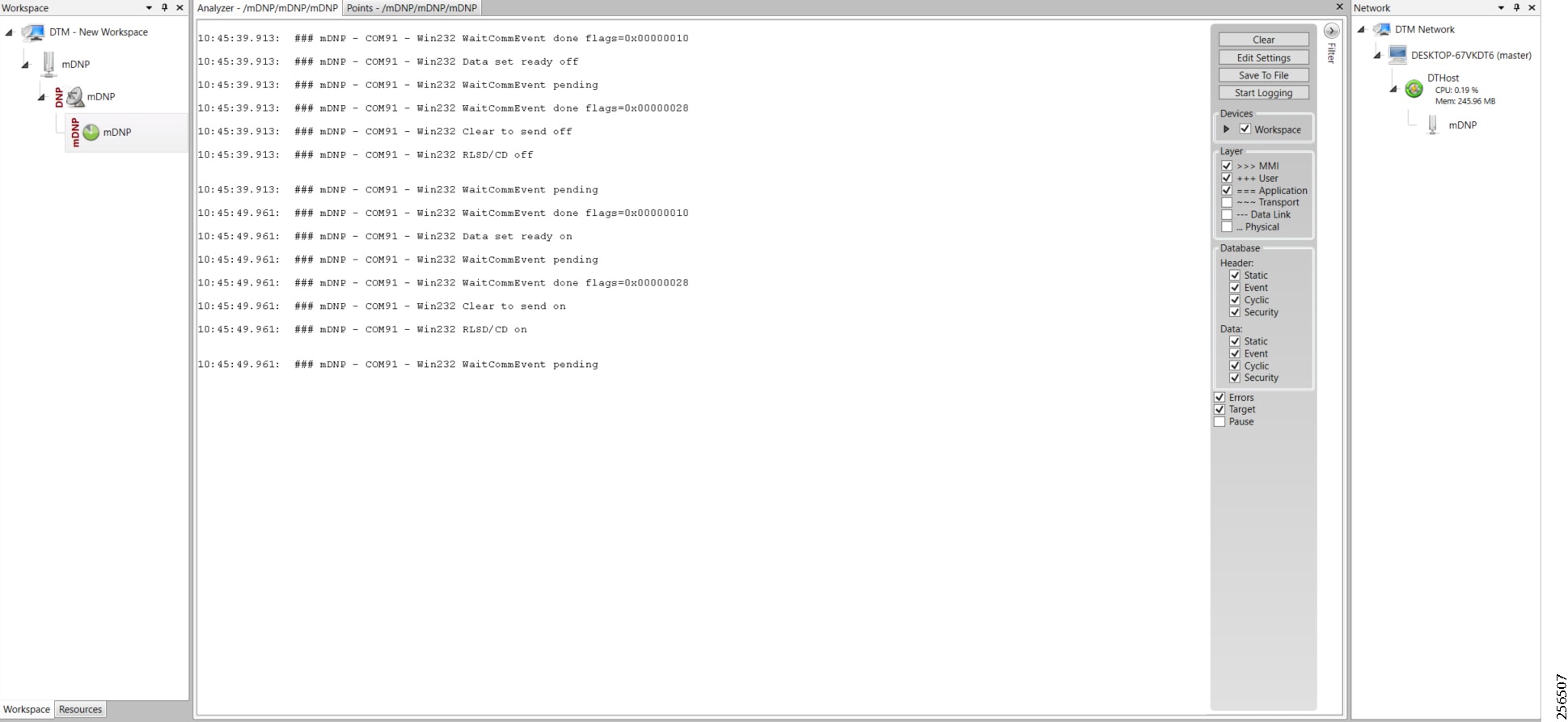
However, when the General Interrogation command is executed, the values of all the registers are displayed on the Master Analyzer shown in Figure 73.
Figure 73 Master Analyzer Logs after Poll Operation
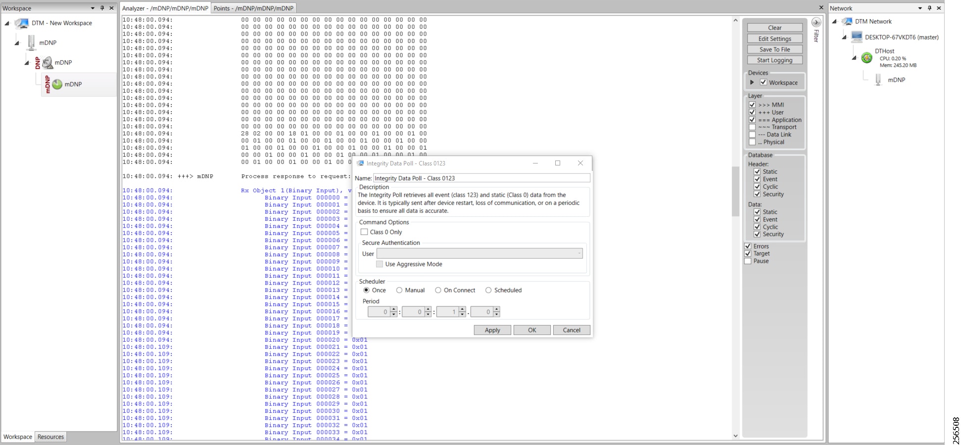
The Control operation basically sends the control command from the SCADA Master to SCADA Slave for the purpose of controlling the operation of end devices. The control command can be executed and the results can be seen on the analyzer. The value of Control Relay Output is changed, which is notified to the Master. Figure 74 shows control relay output status before sending the control command to the Slave.
Figure 74 Slave Register before Control Operation
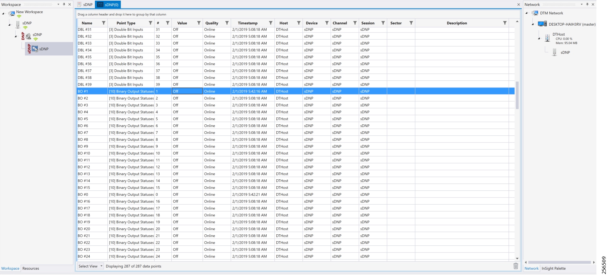
Figure 75 shows how SCADA Master sends the control command.
Figure 75 Master Control Operation
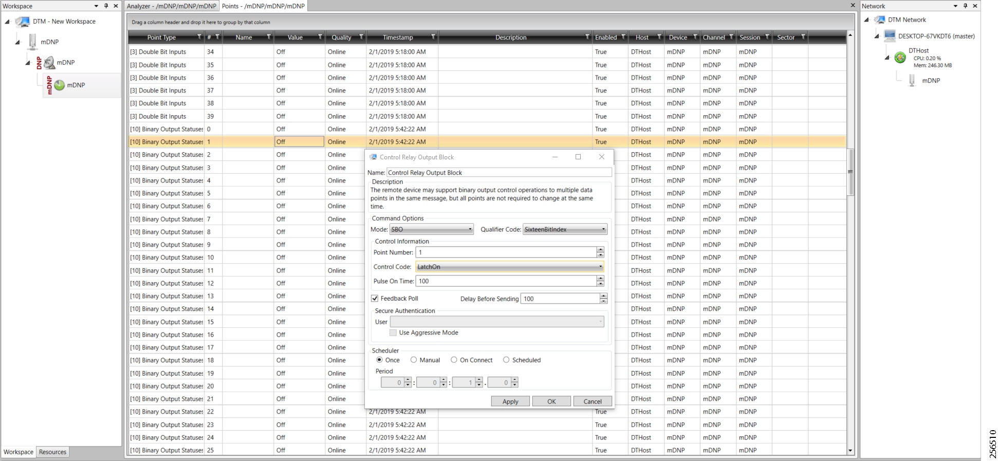
Figure 76 shows the Control Relay Output status changed on SCADA Master.
Figure 76 Slave Register after Control Operation

Unsolicited Reporting is initiated by the Slave, which is connected to the DA Gateway. Changes to the value of the Slave register are reported to the SCADA Master. This notification can be seen on the Master Analyzer. Figure 77 shows an empty screen of the SCADA Master Analyzer before any unsolicited reporting.

Figure 78 shows that the binary input of the Slave is going to change. Initially the value of binary input is OFF.
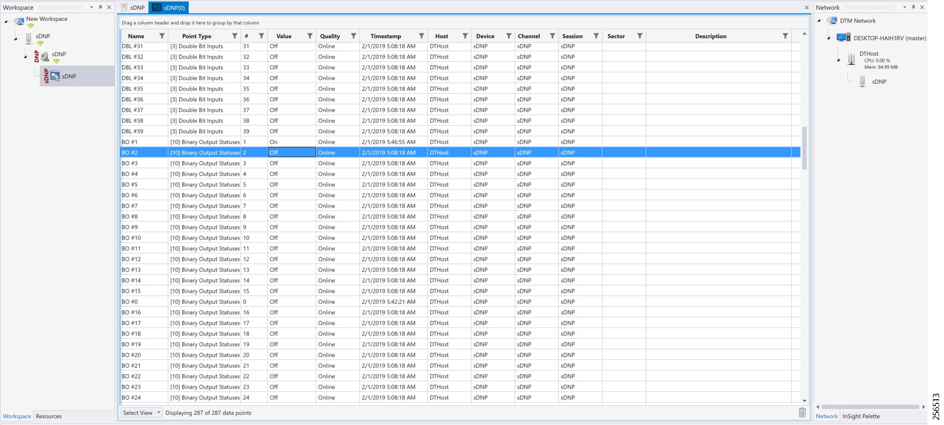
Figure 79 shows the binary input of the Slave is changed from OFF to ON.
Figure 79 Change in Slave Register Value

Figure 80 show the Unsolicited Reporting on the analyzer. The value of Binary Inputs is changed and the same is notified to the Master.
Figure 80 Master Analyzer after Change in Register Value
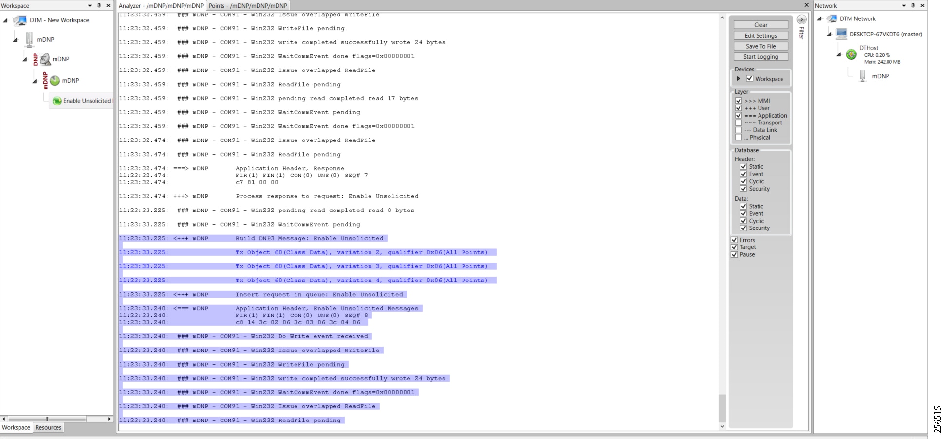
SCADA Gateway
Protocols Validated
The protocols we have validated for this release are DNP3 and DNP3 IP.
Flow Diagram
Figure 81 DNP3-to-DNP3 IP Protocol Translation Control Flow
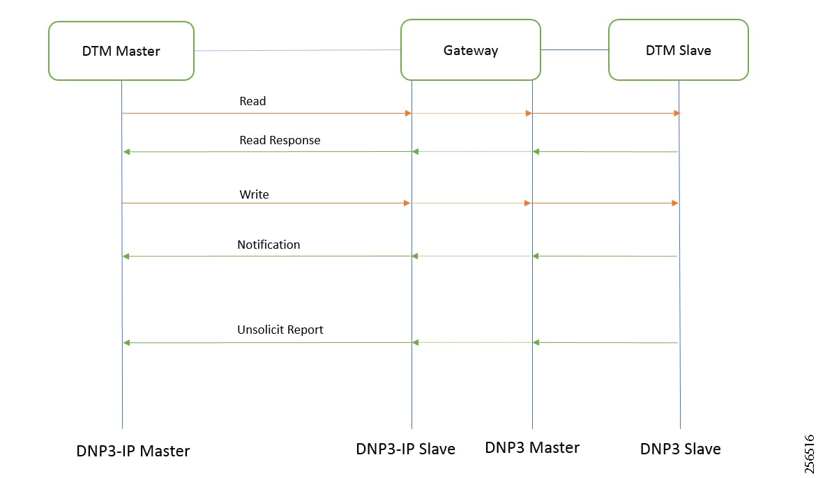
As shown in Figure 81, the DTM Master can read and write the Slave via the DA Gateway using protocol translation. The Slave can send the Unsolicited Reporting to the Master via the DA Gateway using protocol translation.
IR807 DA SCADA Gateway Configuration
As per the topology, the interface connected to SCADA Slave has the following configuration:
IR1101 DA SCADA Gateway Configuration
As per the topology, the interface connected to SCADA Slave has the following configuration:
SCADA Master Configuration
As per the topology, the SCADA Master is residing in the Control Center. The following configuration is required in order for the SCADA Master to communicate with SCADA Slave:
1.![]() Open the SCADA Master Application and click Add a new DNP3 Master.
Open the SCADA Master Application and click Add a new DNP3 Master.
2.![]() From the Channel tab, configure the SCADA Master as per Figure 82.
From the Channel tab, configure the SCADA Master as per Figure 82.
3.![]() SCADA Master (in this case configured as TCP Client), interacts with the SCADA Slave, which is configured to act as a TCP Server.
SCADA Master (in this case configured as TCP Client), interacts with the SCADA Slave, which is configured to act as a TCP Server.
4.![]() Populate the remote address field with the Loopback IP of Cellular Gateway.
Populate the remote address field with the Loopback IP of Cellular Gateway.
5.![]() Populate the port with 21000, which is the port used in Cisco IOS Configuration.
Populate the port with 21000, which is the port used in Cisco IOS Configuration.
Figure 82 Master Configuration
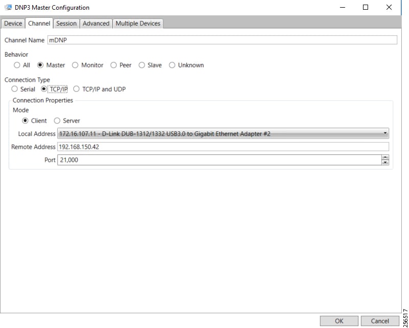
SCADA Slave Configuration
As per the topology, the SCADA Slave is residing in the field area. The following configuration must be required for the SCADA Slave to communicate with SCADA Master. In this implementation, we used SCADA DTMW simulator instead of a real SCADA device.
1.![]() Open the SCADA Slave Application and click Add a new DNP3 Slave.
Open the SCADA Slave Application and click Add a new DNP3 Slave.
2.![]() From the Channel tab, configure the SCADA Master, as per Figure 83.
From the Channel tab, configure the SCADA Master, as per Figure 83.
3.![]() On the SCADA Slave, select the appropriate serial port, baud rate, data bits, stop bits, and parity matching your device configuration.
On the SCADA Slave, select the appropriate serial port, baud rate, data bits, stop bits, and parity matching your device configuration.
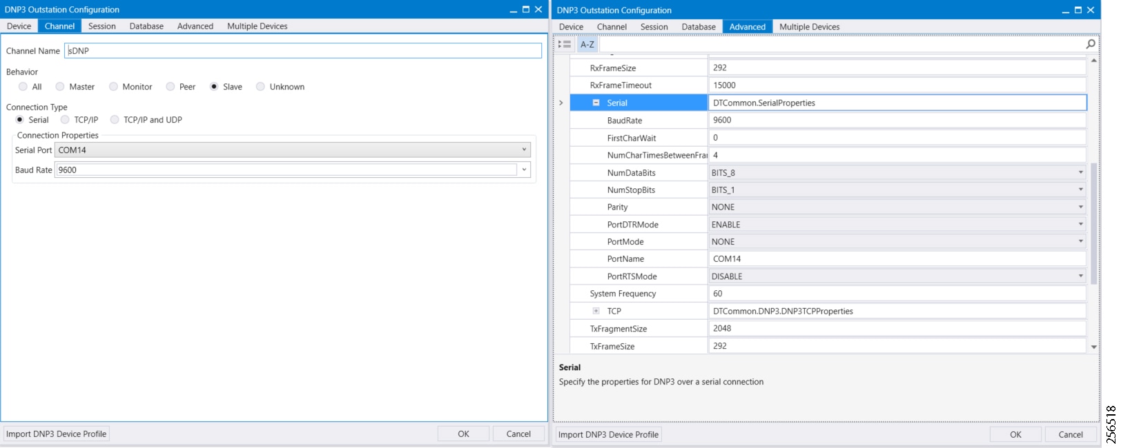
SCADA Operations
The Master and the Slave can communicate via the network. Poll and Control operations are initiated from the Master. Unsolicited Reporting is sent to the Master from the Slave. Figure 84 and Figure 85 show the Poll operation from the SCADA Master. Control and Unsolicited Reporting can also be seen on the Master Analyzer logs.
The Poll operation is performed by the Master, which can execute a general Poll in which all the register values are read and sent to the Master. In Figure 84 and Figure 85, we see a general Poll executed on the Master side.
As Figure 84 shows, the Master Analyzer is initially empty.
Figure 84 Master Analyzer Logs before Poll Operation

However, when the General Interrogation command is executed, the values of all the registers are displayed on the Master Analyzer, as shown in Figure 85.
Figure 85 Master Analyzer Logs after Poll Operation
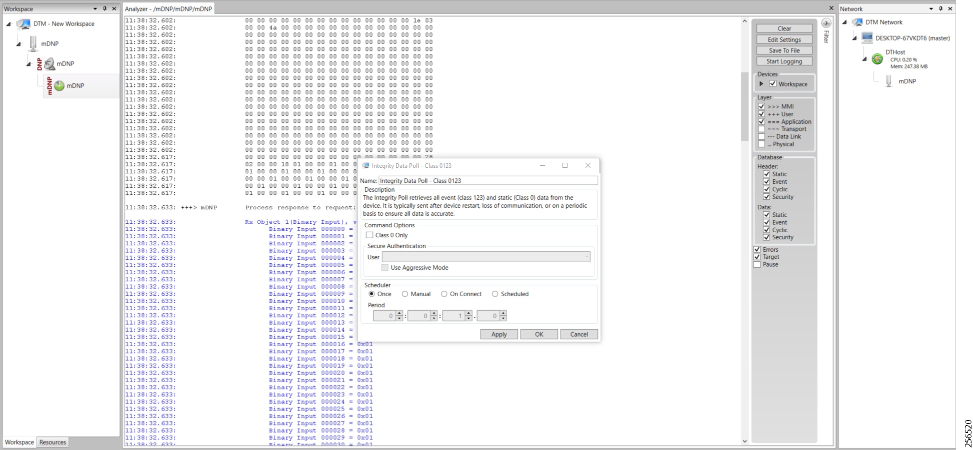
The Control operation basically sends the control command from the SCADA Master to SCADA Slave for the purpose of controlling the operation of end devices. The control command can be executed, and the results can be seen on the analyzer. The value of Control Relay Output is changed and the same is notified to the Master. Figure 86 shows the control relay output status before sending the control command to the Slave.
Figure 86 Slave Register before Control Operation

Figure 87 shows how the SCADA Master sends the control command.
Figure 87 Master Control Operation
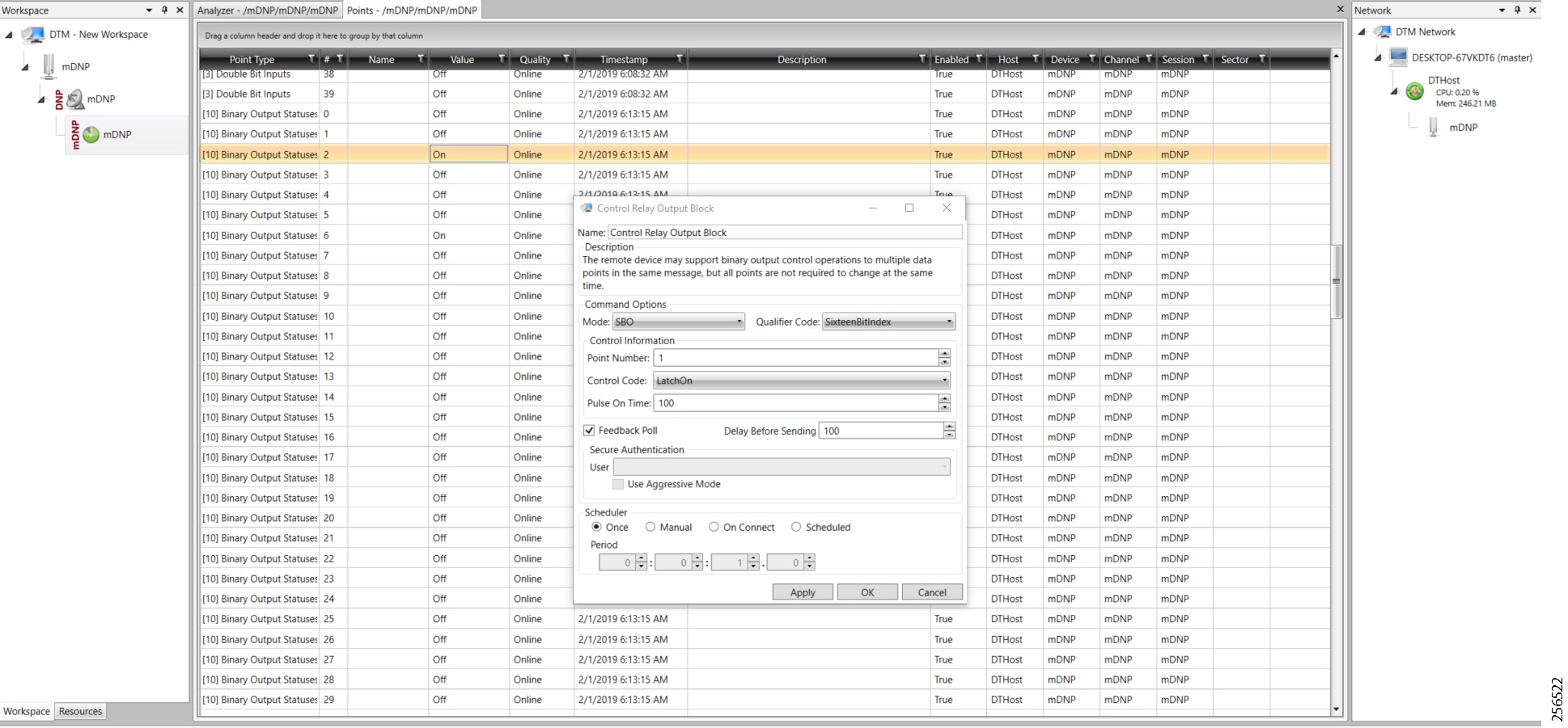
Figure 88 shows the Control Relay Output status changed on the SCADA Master.
Figure 88 Slave Register after Control Operation
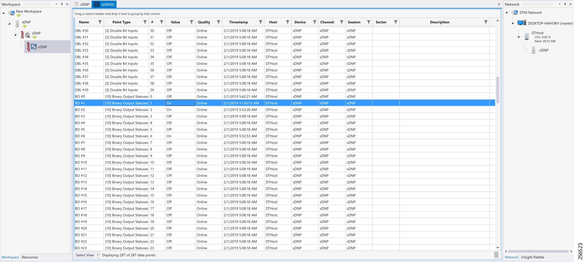
Unsolicited Reporting is initiated by the Slave, which is connected to the DA Gateway. Changes to the value of the Slave register changes are notified to the SCADA Master. This notification can be seen on the Master Analyzer. Figure 89 shows an empty screen of the SCADA Master Analyzer before any unsolicited reporting.
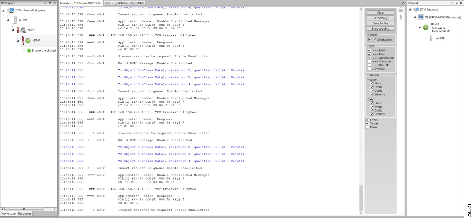
Figure 90 shows the binary input of the Slave that is going to change. Initially the value of binary input is OFF.
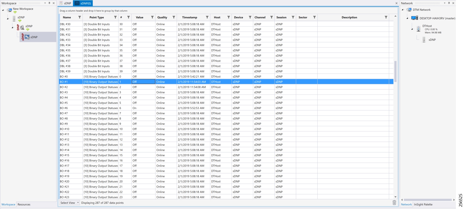
Figure 91 shows the binary input of the Slave is changed from OFF to ON.
Figure 91 Change in Slave Register Value
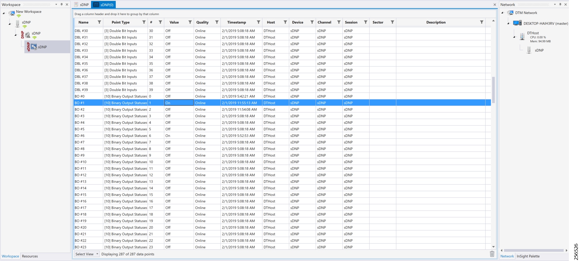
Figure 92 show the Unsolicited Reporting on the analyzer. The value of Binary Inputs is changed and the same is notified to the Master.
Figure 92 Master Analyzer after Change in Register Value
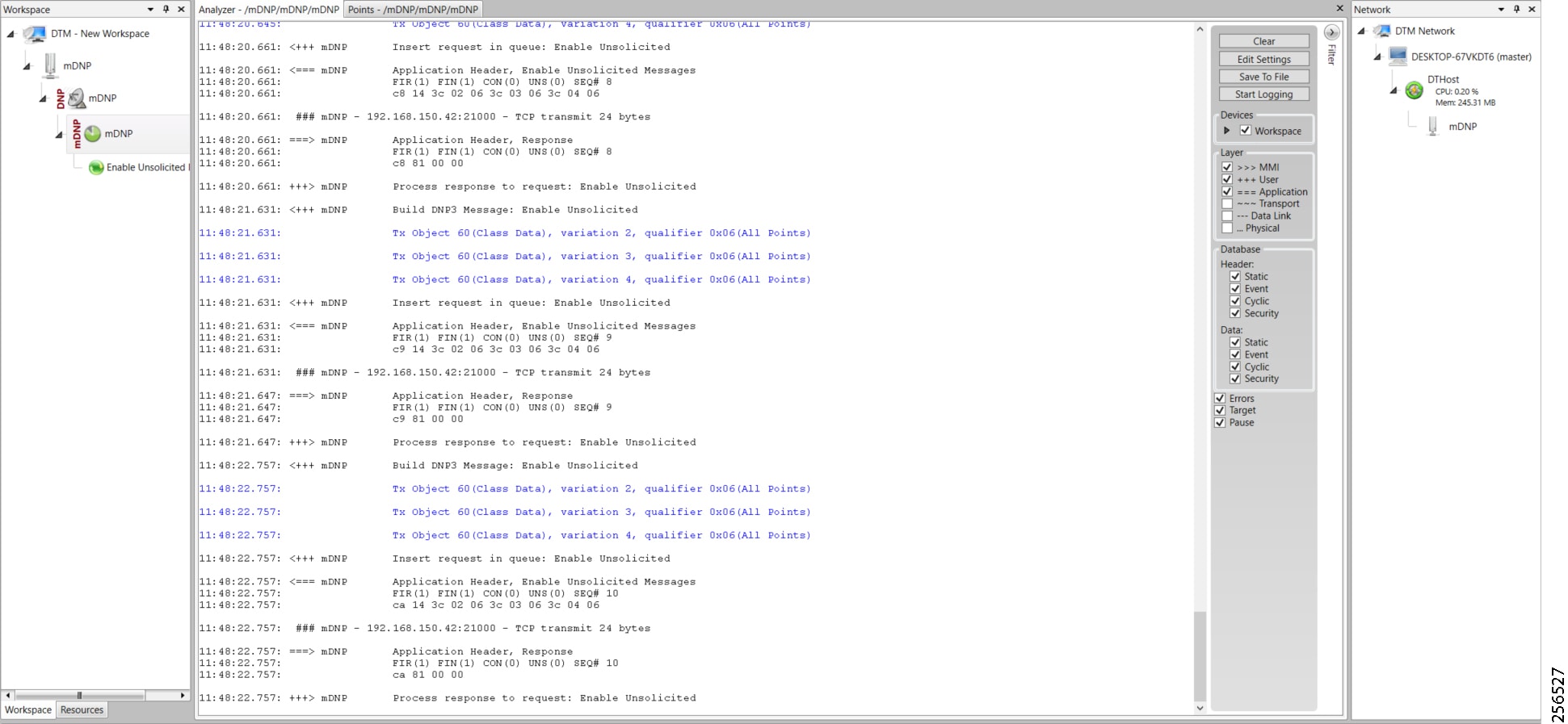
SCADA Communication Scenarios over CR Mesh Network (IEEE 802.15.4)
In this scenario, the DSO will be hosting SCADA applications (Master) in a Control Center. The SCADA Slave is connected to the mesh node via the serial or Ethernet interface. The SCADA Master residing in the DSO Control Center can communicate with the Slave using the DNP3 or DNP3 IP protocol.
Operations that can be executed when the communication protocol is DNP3 or DNP3 IP are as follows:
■![]() Unsolicited Reporting (Slave > Master) - Notification
Unsolicited Reporting (Slave > Master) - Notification
The operations have been executed using a SCADA simulator known as the DTM and Test Harness tool, which has the capability of simulating both the Master and the Slave devices.
■![]() If the endpoint is connected to the mesh node via the Ethernet port, then it is pure IP traffic. The IP address of the endpoint (i.e., IED) can be NAT'd so that the same subnet between the IED and the Ethernet interface of the DA Gateway can be re-used. This approach will ease the deployment.
If the endpoint is connected to the mesh node via the Ethernet port, then it is pure IP traffic. The IP address of the endpoint (i.e., IED) can be NAT'd so that the same subnet between the IED and the Ethernet interface of the DA Gateway can be re-used. This approach will ease the deployment.
■![]() If the endpoint is connected using asynchronous serial (RS-232 or RS-485), then tunneling of serial traffic using Raw Sockets (DNP3) must happen at the mesh node only.
If the endpoint is connected using asynchronous serial (RS-232 or RS-485), then tunneling of serial traffic using Raw Sockets (DNP3) must happen at the mesh node only.
This document focuses on SCADA protocols such as DNP3 and DNP3 IP protocols widely used in the Americas Region with a Control Center.
Figure 93 Feeder Automation CR Mesh Lab Topology
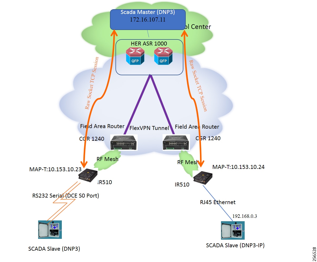
The IR510 is implemented as a mesh node, The CGR1240 is implemented as a FAR, and the ASR 1000s implemented in clustering mode act as a HER, which terminates FlexVPN tunnels from the FAR and the HER.
IP-Enabled SCADA
Protocols Validated
Flow Diagram
Figure 94 DNP3 IP Control Flow
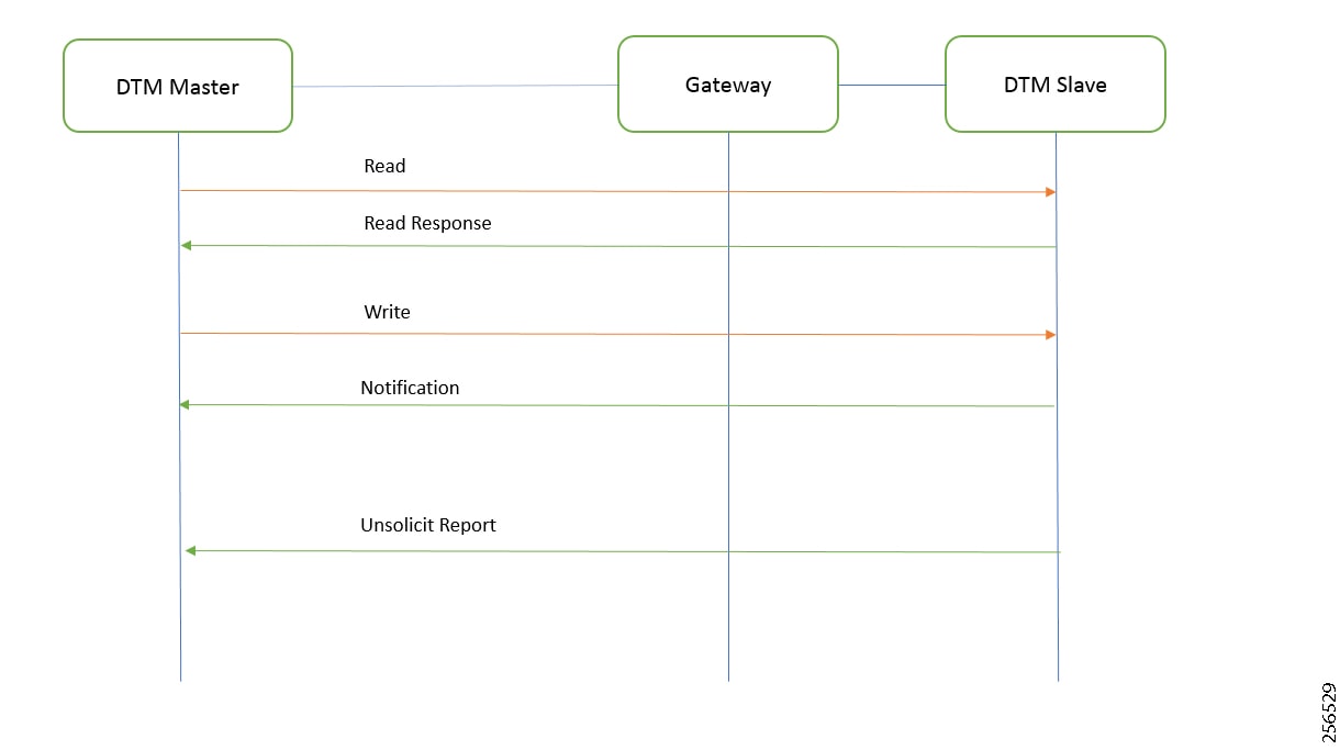
As shown in Figure 94, the SCADA Master can perform a read and write operation to a remote Slave via the DA Gateway. The Slave can send the Unsolicited Reporting to the SCADA Master via the DA Gateway over the IP network.
This section describes the NAT44 configuration of the IR510 device. Basically IPv4 address assignment of the SCADA Slave and the gateway IPv4 address and the port SCADA Slave listens.
Figure 95 IR510 Mesh Node Configuration
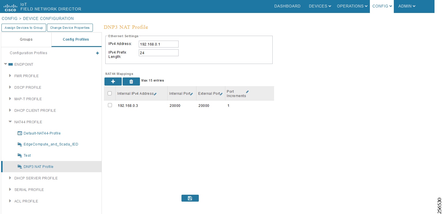
Note: Enable the front panel Ethernet Port on the Configuration template.
For information on NMS management and MAP-T, please refer to Zero Touch Enrollment of Cisco Resilient Mesh Endpoints.
SCADA Master Configuration
As per the topology, the SCADA Master is residing in the Control Center. The following configuration must be required for the SCADA Master to communicate with the SCADA Slave.
1.![]() Open the SCADA Master Application and click Add a new DNP3 Master.
Open the SCADA Master Application and click Add a new DNP3 Master.
2.![]() From the Channel tab, configure the SCADA Master as per Figure 96.
From the Channel tab, configure the SCADA Master as per Figure 96.
The SCADA Master, in this case, is configured as TCP Client, interacting with SCADA Slave, which is configured to act as the TCP Server.
3.![]() Populate the Remote Address field with the Loopback IP of the Cellular Gateway.
Populate the Remote Address field with the Loopback IP of the Cellular Gateway.
4.![]() Populate the port with 20000, which is the port used in Cisco IOS Configuration.
Populate the port with 20000, which is the port used in Cisco IOS Configuration.
For information on MAP-T, please refer to Zero Touch Enrollment of Cisco Resilient Mesh Endpoints.
Figure 96 SCADA Master Configuration
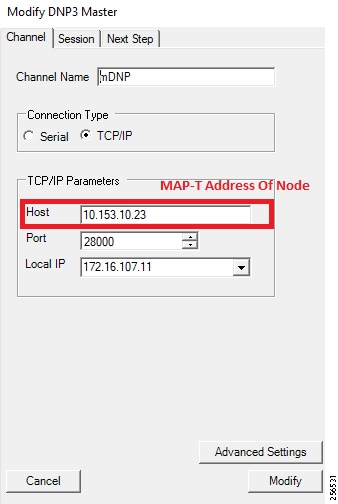
SCADA Slave Configuration
As per the topology, the SCADA Slave is residing in the field area. The following configuration is required for the SCADA Slave to communicate with SCADA Master.
1.![]() Open the SCADA Slave Application and click Add a new DNP3 Slave.
Open the SCADA Slave Application and click Add a new DNP3 Slave.
2.![]() From the Channel tab, configure the SCADA Master as per Figure 97.
From the Channel tab, configure the SCADA Master as per Figure 97.
3.![]() Populate the Remote Address field with the SCADA Master IP.
Populate the Remote Address field with the SCADA Master IP.
4.![]() Populate the port with 20000, which is the port used in the SCADA Master.
Populate the port with 20000, which is the port used in the SCADA Master.
Figure 97 SCADA Slave Configuration
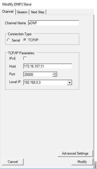
SCADA Operations
The Master and the Slave can communicate via the network. Poll and Control operations are initiated from the Master. Unsolicited Reporting is sent to the Master from the Slave. Figure 98 and Figure 99 show the Poll operation from the SCADA Master. Control, and Unsolicited Reporting can also be seen on the Master Analyzer logs.
The Poll operation is performed by the Master. The Master can execute a general Poll in which all the register values are read and sent to the Master. In Figure 98 and Figure 99, we see a general Poll executed on the Master side.
As per Figure 98 shows, the Master Analyzer is initially empty.
Figure 98 Master Analyzer Logs before Poll Operation
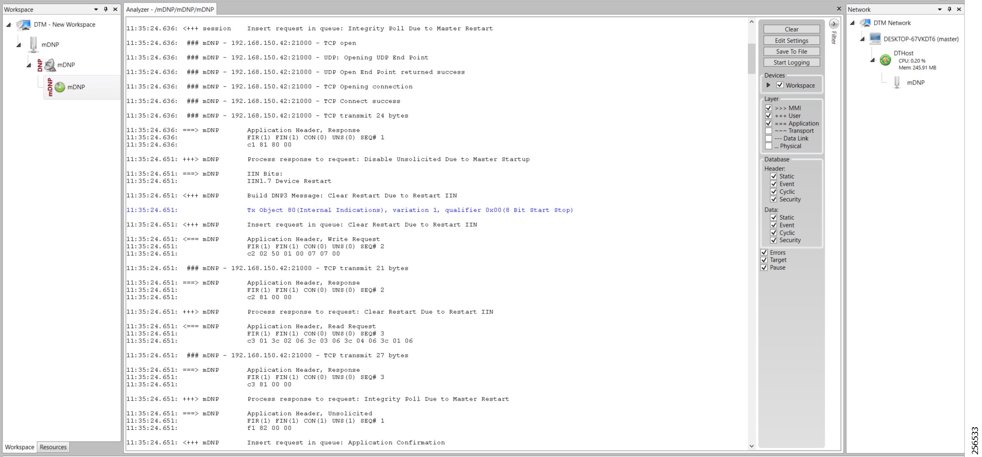
However, when the General Interrogation command is executed, the values of all the registers are displayed on the Master Analyzer, as shown in Figure 99.
Figure 99 Master Analyzer Logs after Poll Operation
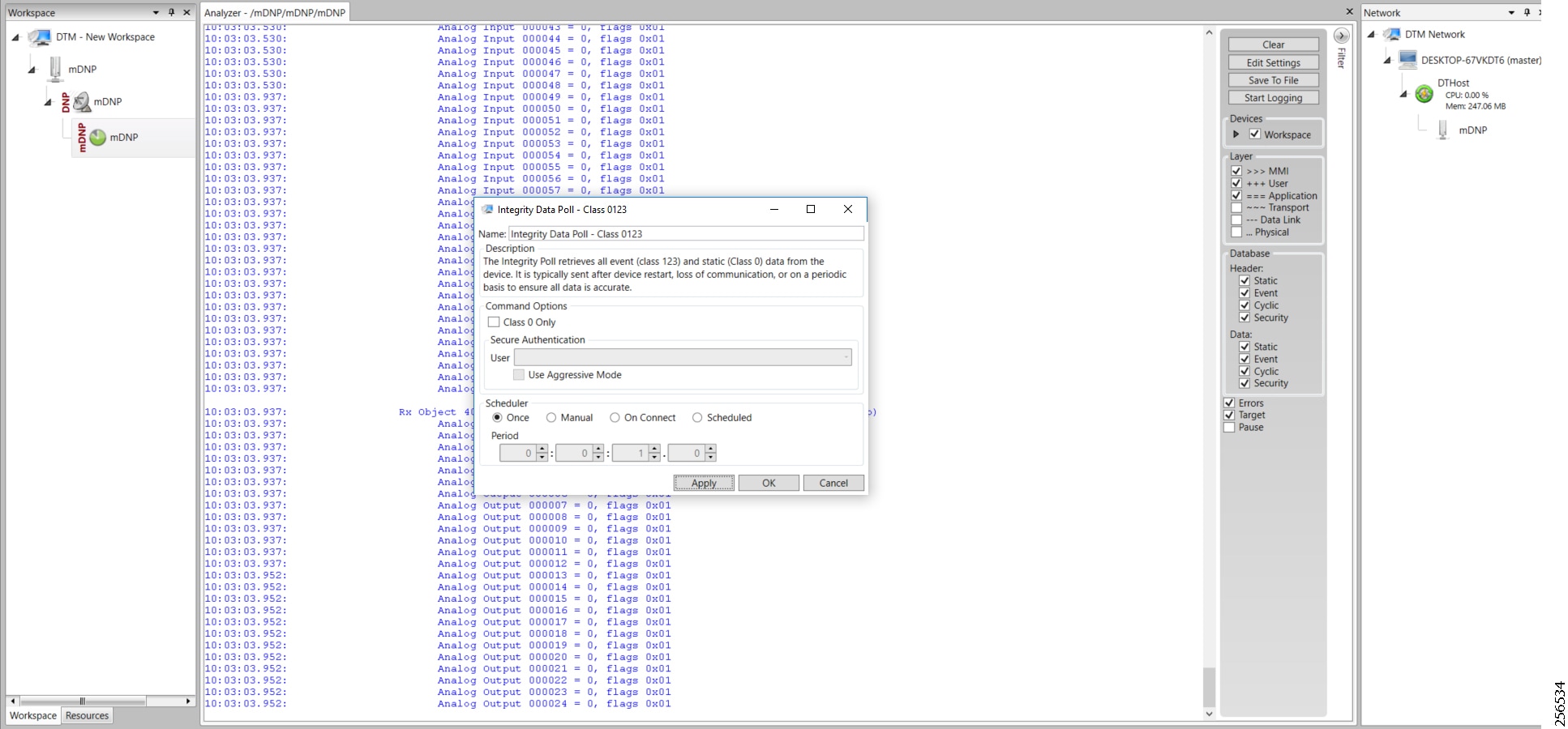
The Control operation basically sends the control command from the SCADA Master to SCADA Slave for the purpose of controlling the operation of end devices. The control command can be executed, and the results can be seen on the analyzer. The value of Control Relay Output is changed and the same is notified to the Master. The SCADA Control operation has been validated in the following sequence of steps.
The Initial Control Relay Output status would be noted on the SCADA Slave.
Figure 100 shows the control relay output status before sending the control command to the Slave.
Figure 100 Slave Register before Control Operation

As Figure 101 shows, a control operation is then performed to modify the value of the control relay output register on the SCADA Slave. This operation is performed from the SCADA Master on the SCADA Slave.
Figure 101 Master Control Operation
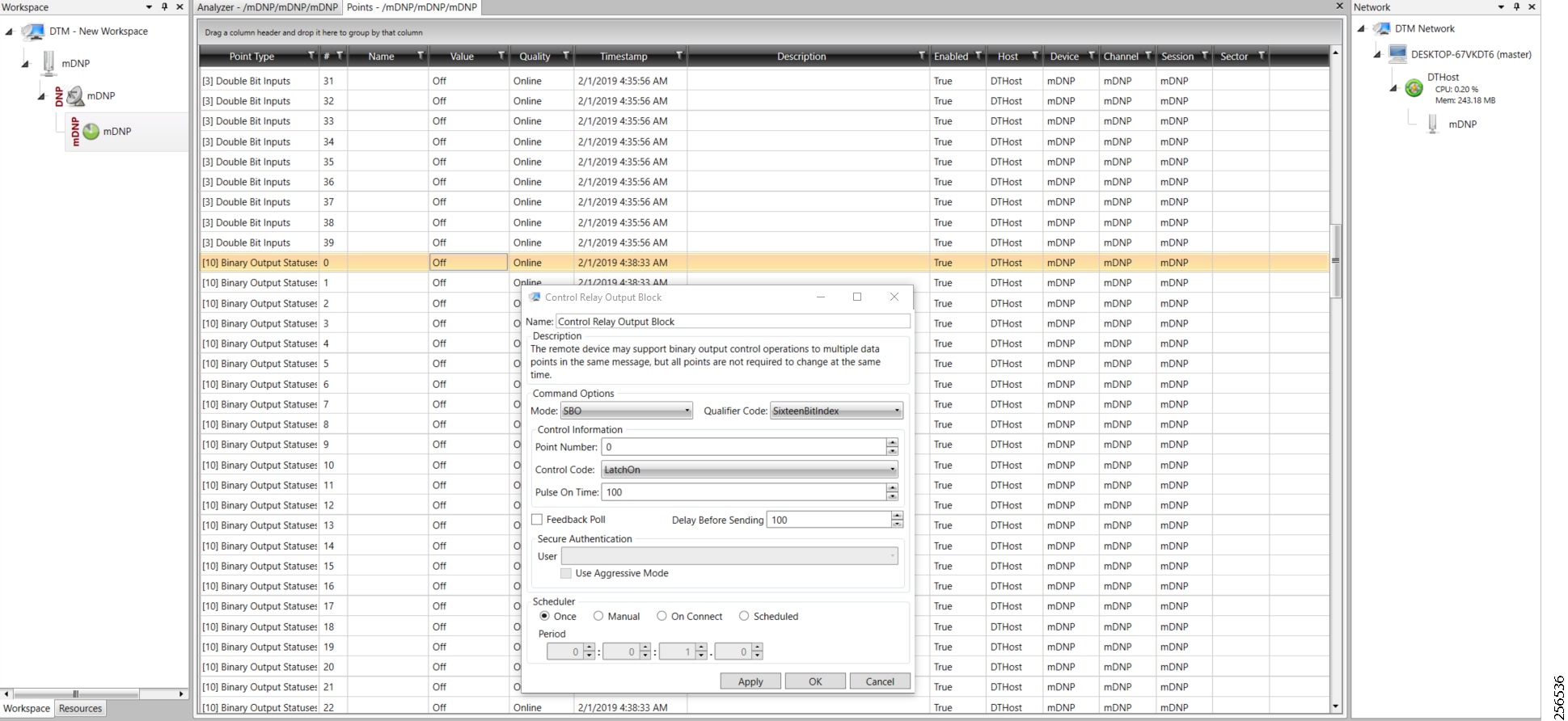
After the control operation is issued from the SCADA Master, the control relay output register of the SCADA Slave is noted. As Figure 102 shows, successful modification of the register value on the SCADA Slave signifies the successful Control operation.
Figure 102 Slave Register after Control Operation
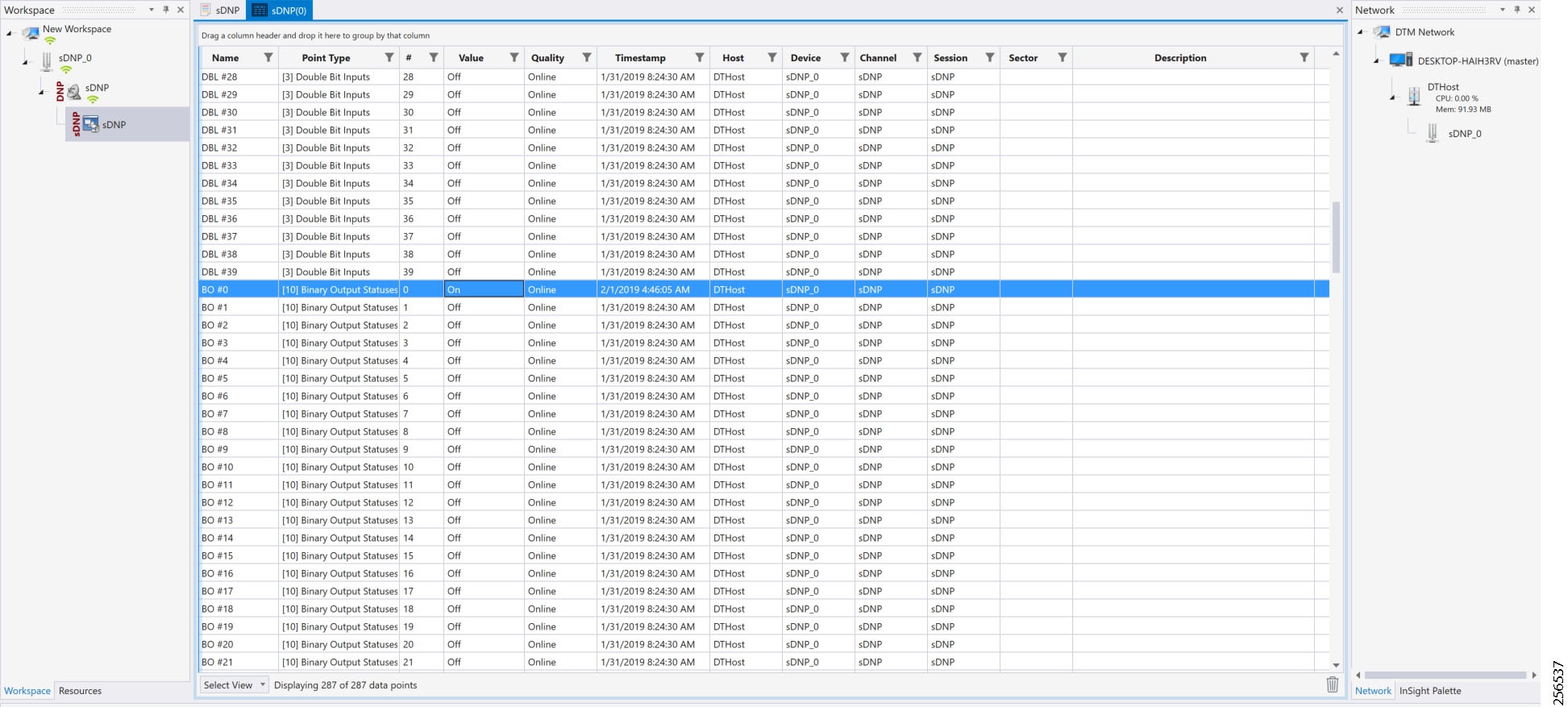
Unsolicited Reporting is initiated by the Slave, which is connected to the DA Gateway. Changes to the value of the Slave register are reported to the SCADA Master. This notification can be seen on the Master Analyzer. Figure 103 shows an empty screen of the SCADA Master Analyzer before any unsolicited reporting.
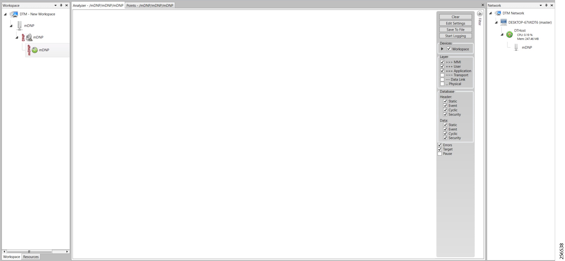
Figure 104 shows binary input of the Slave that is going to change. Initially the value of binary input is OFF.
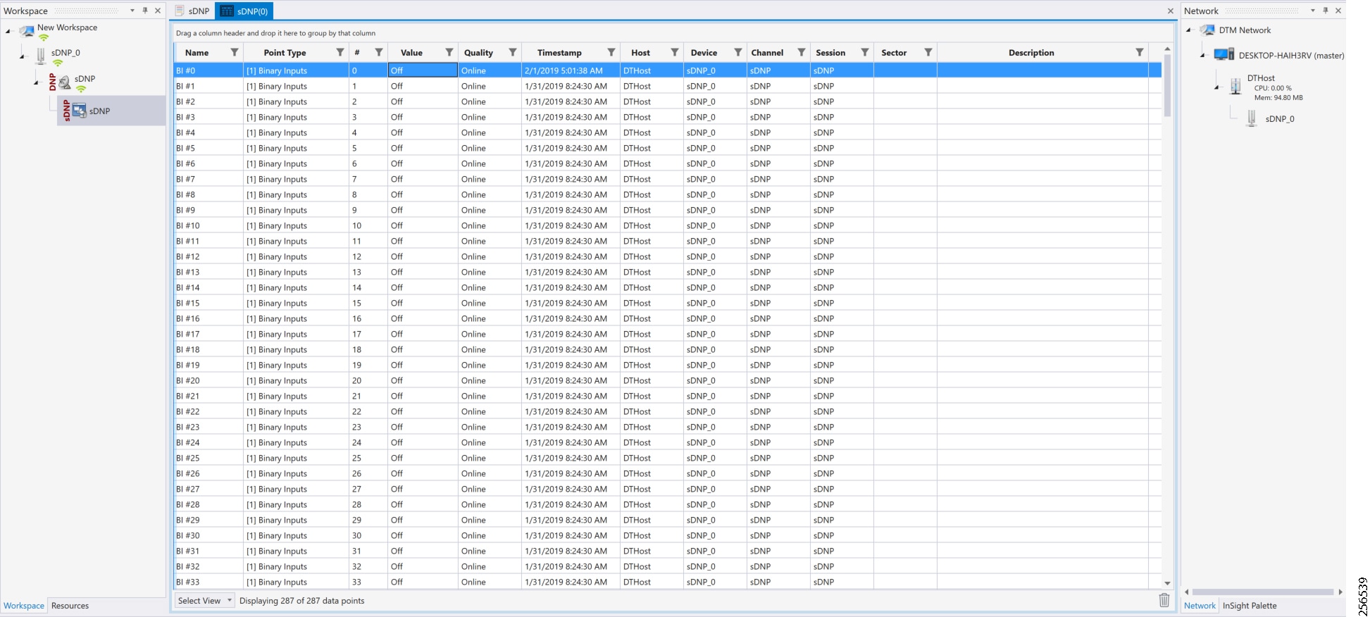
Figure 105 shows the binary input of the Slave is changed from OFF to ON.
Figure 105 Change in Slave Register Value

Figure 106 show the Unsolicited Reporting on the analyzer. The value of Binary Inputs is changed and the same is notified to the Master.
Figure 106 Master Analyzer after Change in Register Value
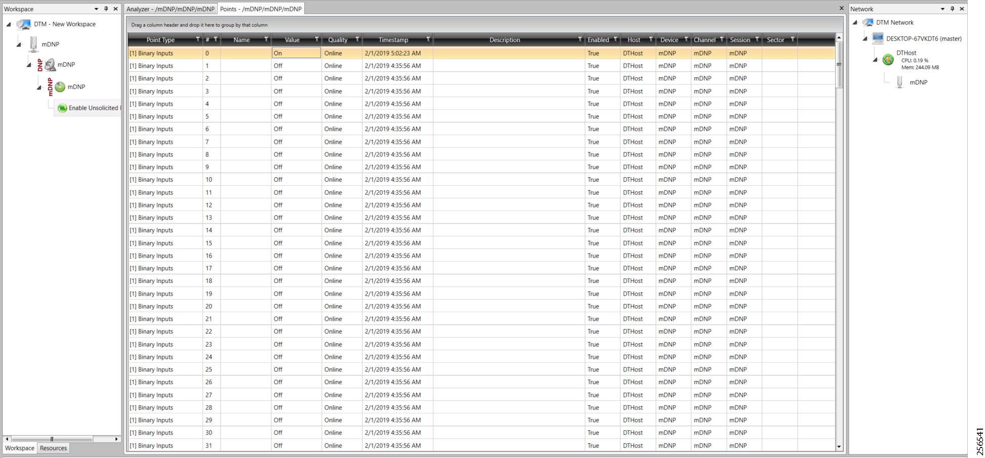
SCADA Communication with Serial-based SCADA using Raw Socket UDP
Protocols Validated
Flow Diagram
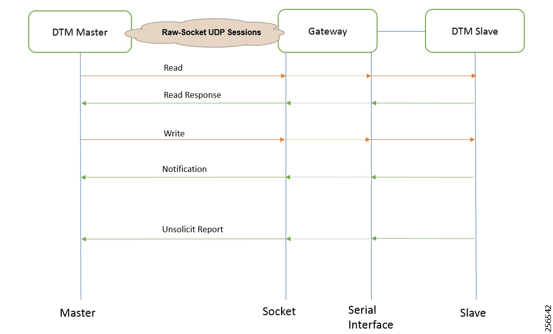
As shown in Figure 107, the SCADA Master can poll and control the Slave via the DA Gateway using UDP Raw Socket. The Slave can send the Unsolicited Reporting to the Master via the DA Gateway using UDP Raw Socket.
IR510 Mesh Node Raw Socket UDP Configuration
As per the topology, the SCADA Master resides in the Control Center. Three step configurations on FND:
2.![]() Linking of the serial profile to the configuration template
Linking of the serial profile to the configuration template
3.![]() Configuration push to the device
Configuration push to the device
The following serial configuration profile requires the mesh node to communicate with the SCADA Master.
■![]() Peer IP Address—SCADA Master IP Address.
Peer IP Address—SCADA Master IP Address.
■![]() Peer Port—SCADA Master Port Address, where SCADA Master is listening.
Peer Port—SCADA Master Port Address, where SCADA Master is listening.
■![]() Local Port—This Port signifies the Raw Socket initiator port number. In this case, the IR510 node is the Raw Socket initiator.
Local Port—This Port signifies the Raw Socket initiator port number. In this case, the IR510 node is the Raw Socket initiator.
■![]() Packet Length & Packet Timer—Any integer value.
Packet Length & Packet Timer—Any integer value.
■![]() Special Character—You can specify a character that will trigger the IR510 to packetize the data accumulated in its buffer and send it to the Raw Socket peer. When the special character (for example, a CR/LF) is received, the IR510 packetizes the accumulated data and sends it to the Raw Socket peer.
Special Character—You can specify a character that will trigger the IR510 to packetize the data accumulated in its buffer and send it to the Raw Socket peer. When the special character (for example, a CR/LF) is received, the IR510 packetizes the accumulated data and sends it to the Raw Socket peer.
Figure 108 IR510 Mesh Node Raw Socket UDP Configuration
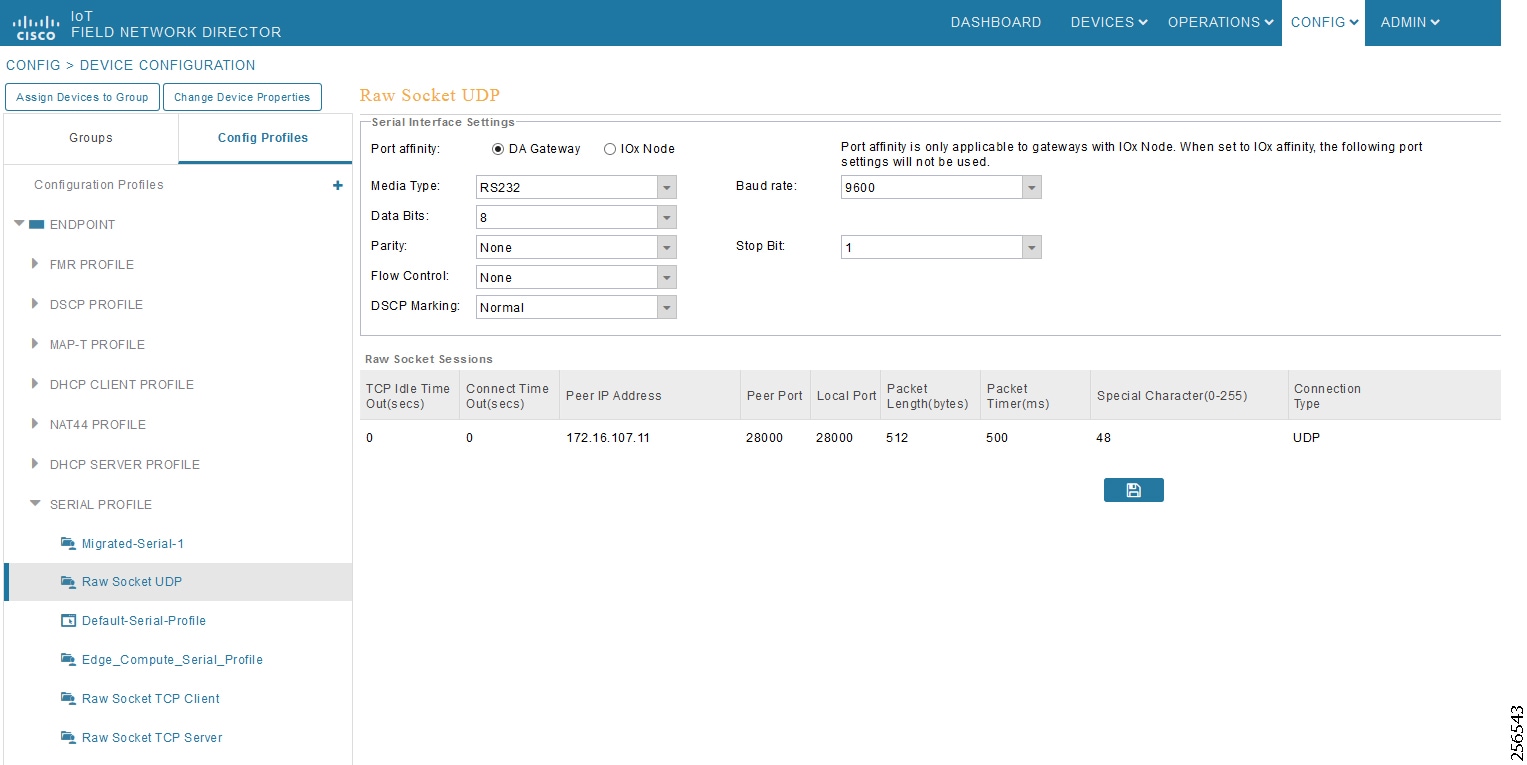
SCADA Master Configuration
As per the topology, the SCADA Master resides in the Control Center. The following configuration is required for the SCADA Master to communicate with the SCADA Slave. In this implementation, DNP3-IP acted as a SCADA Master instead of the DNP3 Raw Socket Server. The configuration provided below is specific to DNP3-IP.
1.![]() Open the SCADA Master application and click Add a new DNP3 Master.
Open the SCADA Master application and click Add a new DNP3 Master.
2.![]() From the Channel tab, configure the SCADA Master as per Figure 109.
From the Channel tab, configure the SCADA Master as per Figure 109.
–![]() Network Type—To configure a Master or Slave as a UDP only device, NetworkType should be set to UDP_ONLY.
Network Type—To configure a Master or Slave as a UDP only device, NetworkType should be set to UDP_ONLY.
–![]() Type—This can be configured as UDP_TCP.
Type—This can be configured as UDP_TCP.
–![]() DestUDPPort—Port Address of Raw Socket initiator or client.
DestUDPPort—Port Address of Raw Socket initiator or client.
–![]() LocalUDPPort—Port Address of the SCADA Master.
LocalUDPPort—Port Address of the SCADA Master.
–![]() WinTCPinAddress—MAP-T Address of the Node.
WinTCPinAddress—MAP-T Address of the Node.
–![]() WinTCPipPort—TCP Parameter 'WinTCPipPort' will be the local port number on which datagrams will be received.
WinTCPipPort—TCP Parameter 'WinTCPipPort' will be the local port number on which datagrams will be received.
–![]() WinTCPmode—To configure a Master or Slave as a UDP-only device, WinTCPmode should be changed to UDP.
WinTCPmode—To configure a Master or Slave as a UDP-only device, WinTCPmode should be changed to UDP.
Figure 109 SCADA Master Configuration
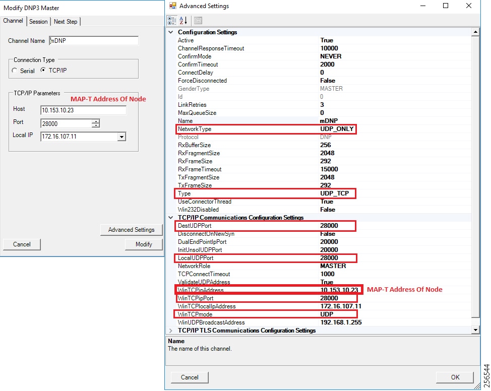
SCADA Slave Configuration
As per the topology, the SCADA Slave resides in the field area. The following configuration is required for the SCADA Slave to communicate with the SCADA Master. In this implementation, we used the SCADA DTMW simulator instead of a real SCADA device.
1.![]() Open the SCADA Slave application and click Add a new DNP3 Slave.
Open the SCADA Slave application and click Add a new DNP3 Slave.
2.![]() From the Channel tab, configure the SCADA Master as per Figure 110.
From the Channel tab, configure the SCADA Master as per Figure 110.
3.![]() On the SCADA Slave, select the appropriate serial port, baud rate, data bits, stop bits and parity matching of your device configuration.
On the SCADA Slave, select the appropriate serial port, baud rate, data bits, stop bits and parity matching of your device configuration.
Figure 110 SCADA Slave Configuration

SCADA Operations
The Master and the Slave can communicate via the network. Poll and Control operations are initiated from the Master. Unsolicited Reporting is sent to the Master from the Slave. Figure 111 and Figure 112 show the Poll operation from the SCADA Master. Control and Unsolicited Reporting can also be seen on the Master Analyzer logs.
Poll
The Poll operation is performed by the Master. The Master can execute a general Poll in which all the register values are read and sent to the Master. In Figure 111 and Figure 112, we see a general Poll executed on the Master side.
As Figure 111 shows, the Master Analyzer is initially empty.
Figure 111 Master Analyzer Logs before Poll Operation
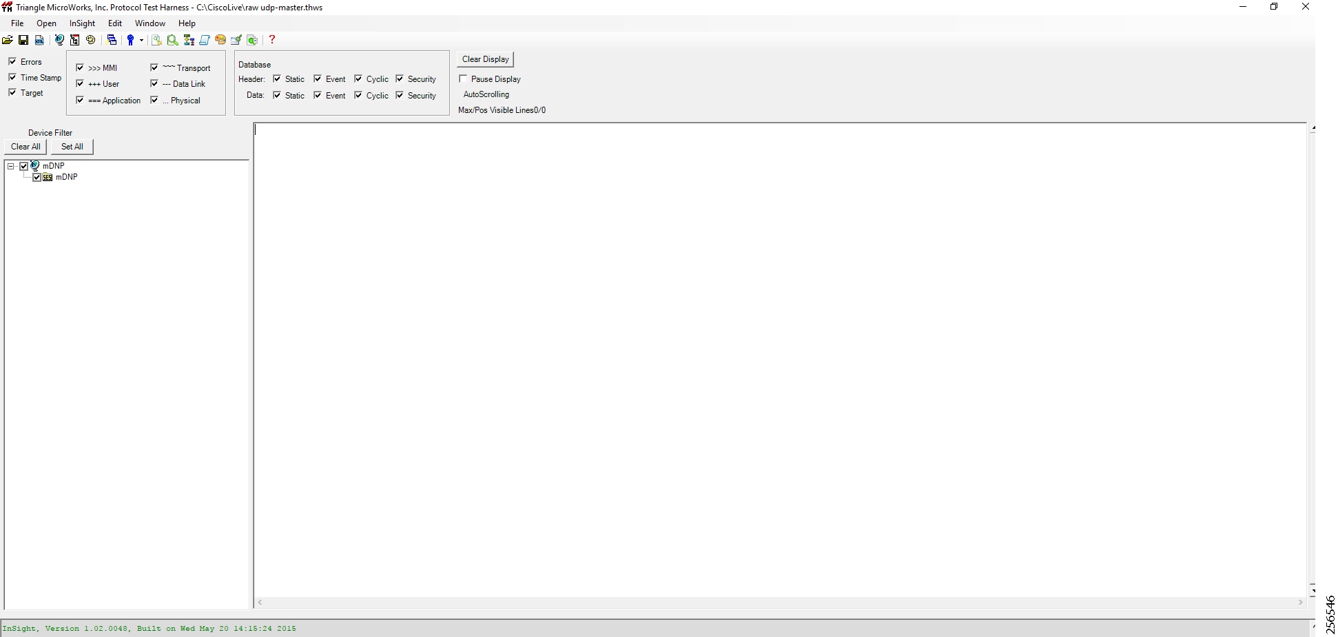
However, when the General Interrogation command is executed, the values of all the registers are displayed on the Master Analyzer shown in Figure 112.
Figure 112 Master Analyzer Logs after Poll Operation
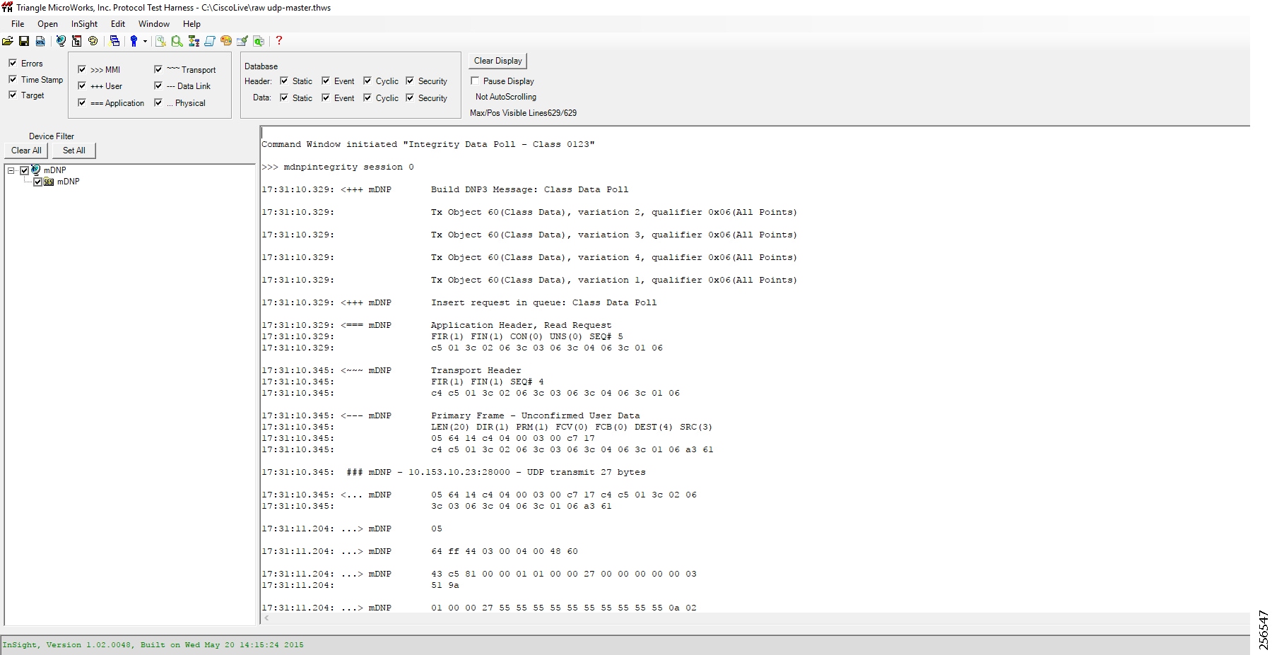
Control
The Control operation basically sends the control command from the SCADA Master to the SCADA Slave for the purpose of controlling the operation of end devices. The control command can be executed, and the results can be seen on the analyzer. The value of Control Relay Output is changed and the same is notified to the Master. SCADA Control operation has been validated in the following sequence of steps:
1.![]() The Initial Control Relay Output status would be noted down on SCADA Slave. Figure 113 shows the control relay output status before sending the control command to the Slave.
The Initial Control Relay Output status would be noted down on SCADA Slave. Figure 113 shows the control relay output status before sending the control command to the Slave.
Figure 113 Slave Register before Control Operation
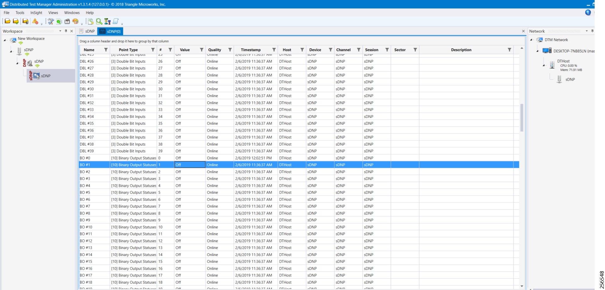
2.![]() As Figure 114 shows, a control operation is then performed to modify the value of the control relay output register on the SCADA Slave. This operation is performed from the SCADA Master on the SCADA Slave.
As Figure 114 shows, a control operation is then performed to modify the value of the control relay output register on the SCADA Slave. This operation is performed from the SCADA Master on the SCADA Slave.
Figure 114 Master Control Operation
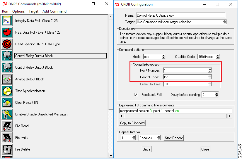
3.![]() After the control operation is issued from the SCADA Master, the control relay output register of the SCADA Slave is noted down. As Figure 115 shows, successful modification of the register value on the SCADA Slave signifies the successful Control operation.
After the control operation is issued from the SCADA Master, the control relay output register of the SCADA Slave is noted down. As Figure 115 shows, successful modification of the register value on the SCADA Slave signifies the successful Control operation.
Figure 115 Slave Register after Control Operation
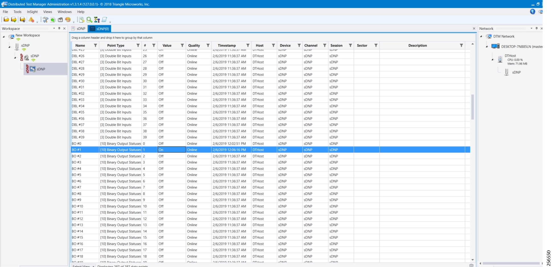
Unsolicited Reporting
Unsolicited Reporting is initiated by the Slave, which is connected to the DA Gateway. Changes to the value of the Slave register are reported to the SCADA-Master. This notification can be seen on the Master Analyzer. Figure 116 shows the SCADA Master Analyzer before any unsolicited reporting of binary input is in the OFF state.
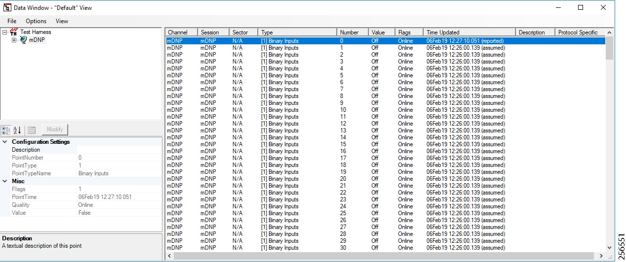
1.![]() Figure 117 shows that the binary input of the Slave is going to change. Initially, the value of binary input is OFF.
Figure 117 shows that the binary input of the Slave is going to change. Initially, the value of binary input is OFF.
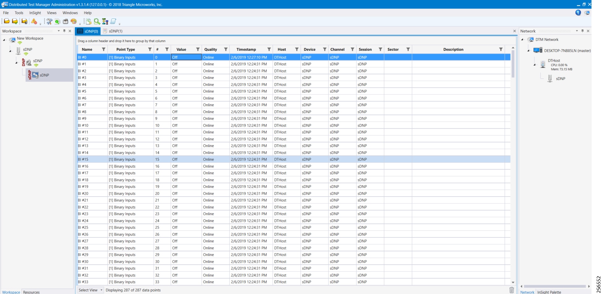
2.![]() Figure 118 shows that the binary input of the Slave is changed from OFF to ON.
Figure 118 shows that the binary input of the Slave is changed from OFF to ON.
Figure 118 Change in Slave Register Value
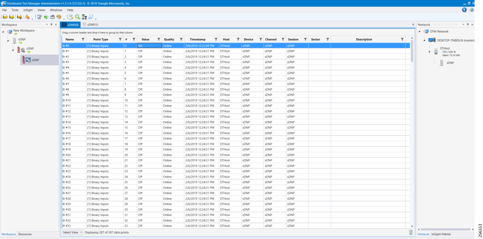
3.![]() Figure 119 show the Unsolicited Reporting on the analyzer. The value of Binary Inputs is changed and the same is reported to the Master.
Figure 119 show the Unsolicited Reporting on the analyzer. The value of Binary Inputs is changed and the same is reported to the Master.
Figure 119 Master Analyzer after Change in Register Value
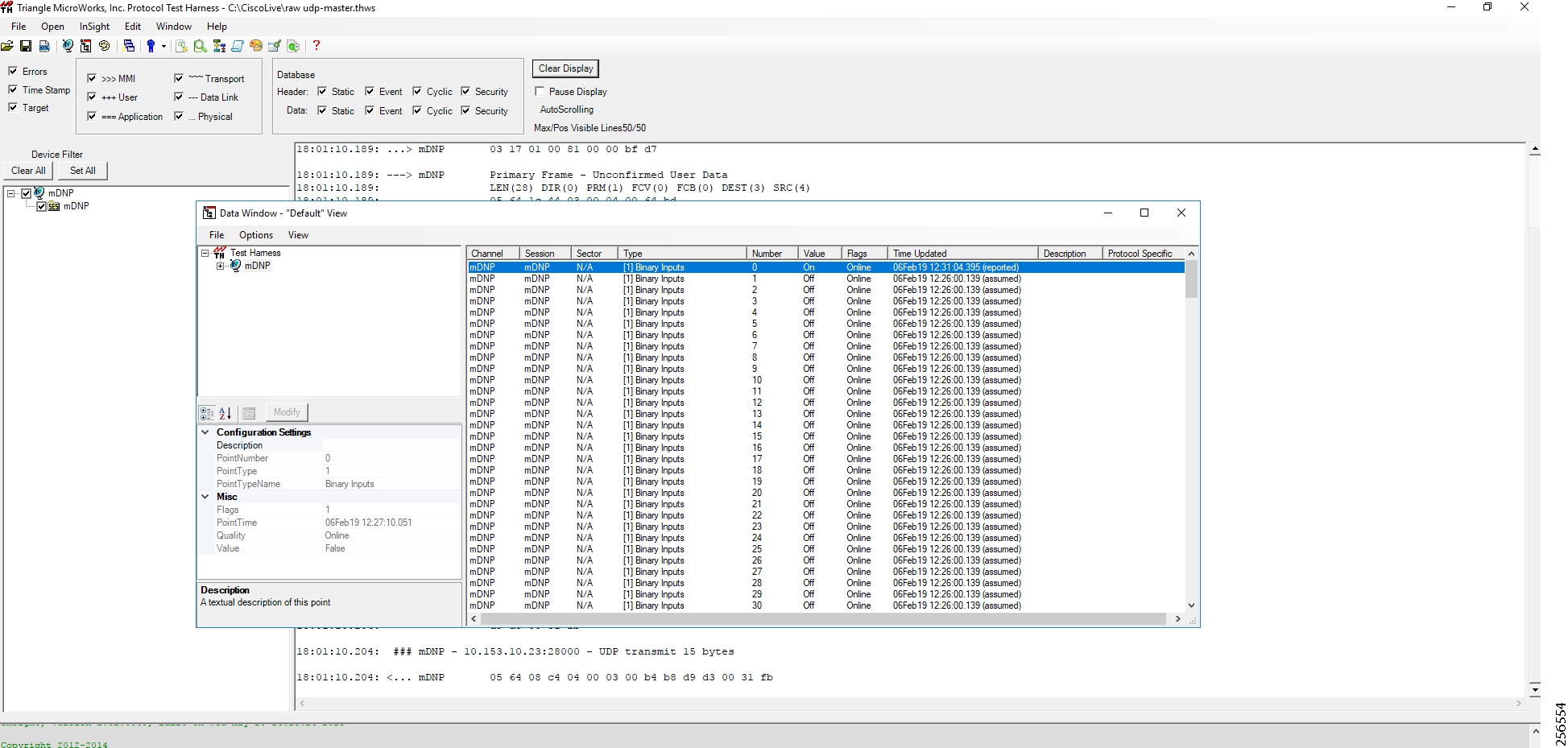
SCADA Communication with Serial-based SCADA using Raw Socket TCP
IR510 Mesh Node Raw Socket TCP Client Configuration
As per the topology, the SCADA Master resides in the Control Center. Three step configurations on FND???
1.![]() Creating the serial profile.
Creating the serial profile.
2.![]() Linking the serial profile to the configuration template.
Linking the serial profile to the configuration template.
3.![]() Pushing the configuration to the device.
Pushing the configuration to the device.
The following serial configuration profile requires a mesh node to communicate with the SCADA Master.
■![]() Peer IP Address—SCADA Master IP Address.
Peer IP Address—SCADA Master IP Address.
■![]() Peer Port—SCADA Master Port Address, where SCADA Master is listening.
Peer Port—SCADA Master Port Address, where SCADA Master is listening.
■![]() Local Port—This Port signifies the Raw Socket initiator port number. In this case, the IR510 node is the Raw Socket initiator.
Local Port—This Port signifies the Raw Socket initiator port number. In this case, the IR510 node is the Raw Socket initiator.
■![]() Packet Length & Packet Timer—Any integer value.
Packet Length & Packet Timer—Any integer value.
■![]() Special Character—You can specify a character that will trigger the IR510 to packetize the data accumulated in its buffer and send it to the Raw Socket peer. When the special character (for example, a CR/LF) is received, the IR510 packetizes the accumulated data and sends it to the Raw Socket peer.
Special Character—You can specify a character that will trigger the IR510 to packetize the data accumulated in its buffer and send it to the Raw Socket peer. When the special character (for example, a CR/LF) is received, the IR510 packetizes the accumulated data and sends it to the Raw Socket peer.
Figure 120 IR510 Mesh Node Raw Socket Configuration
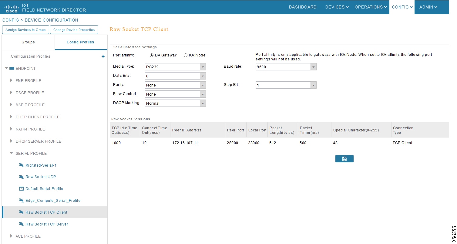
Legacy SCADA (Raw Socket TCP Server)
IR510 Mesh Node Raw Socket UDP Configuration
As per the topology, the SCADA Master is residing in the Control Center. Three step configurations on FND.??
1.![]() Creating the serial profile.
Creating the serial profile.
2.![]() Linking the serial profile to the configuration template.
Linking the serial profile to the configuration template.
3.![]() Pushing configuration to the device.
Pushing configuration to the device.
The following serial configuration profile requires the mesh node to communicate with the SCADA Master:
■![]() Peer IP Address—SCADA Master IP Address.
Peer IP Address—SCADA Master IP Address.
■![]() Peer Port—SCADA Master Port Address, where SCADA Master is listening.
Peer Port—SCADA Master Port Address, where SCADA Master is listening.
■![]() Local Port—This Port signifies the Raw Socket initiator port number. In this case IR510 node is the Raw Socket initiator.
Local Port—This Port signifies the Raw Socket initiator port number. In this case IR510 node is the Raw Socket initiator.
■![]() Packet Length & Packet Timer—Any integer value.
Packet Length & Packet Timer—Any integer value.
■![]() Special Character—You can specify a character that will trigger the IR510 to packetize the data accumulated in its buffer and send it to the Raw Socket peer. When the special character (for example, a CR/LF) is received, the IR510 packetizes the accumulated data and sends it to the Raw Socket peer.
Special Character—You can specify a character that will trigger the IR510 to packetize the data accumulated in its buffer and send it to the Raw Socket peer. When the special character (for example, a CR/LF) is received, the IR510 packetizes the accumulated data and sends it to the Raw Socket peer.
Figure 121 IR510 Mesh Node Raw Socket TCP Server Configuration
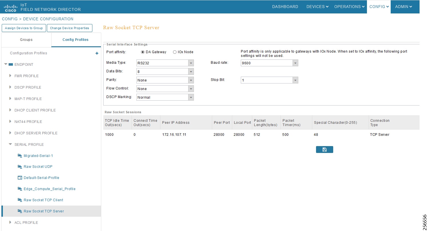
End-to-End Application Use Case Scenarios
This chapter includes the following major topics:
■![]() VAR Control (Power Factor Regulation)
VAR Control (Power Factor Regulation)
■![]() Voltage Control (Conservation Voltage Reduction)
Voltage Control (Conservation Voltage Reduction)
■![]() Fault Location, Isolation, and Service Restoration (FLISR)
Fault Location, Isolation, and Service Restoration (FLISR)
Volt/VAR
The main purpose of Volt/VAR Control (VVC) is to maintain acceptable voltage level at all points along the distribution feeder under all loading conditions. For optimizing the movement of electric energy, it is necessary to minimize the reactive power flows, which is done locally by reactive power compensation equipment such as capacitor banks.
The advanced VVO (Volt/VAR Optimization) application will be using a two-way communication infrastructure and remote control capability for capacitor banks and voltage-regulating transformers to optimize the energy delivery efficiency at distribution level. In fact, the reactive power flow creates a voltage drop on inductive element of wires. Therefore, in order to keep the voltage always within certain limits, the reactive power flow and voltage control must be considered together, as we call it VVC (Volt/VAR Control). For the voltage and reactive power control, load tap changer (LTC) transformers, switched shunt capacitors, and step voltage regulators are used. A minimum requirement for voltage control is the possibility for the operator to maintain the voltage on the feeder at an acceptable range by changing the position of the movable tap changer on a voltage regulator.
Note: Volt/VAR Control = Power Factor Regulation + Conservation Voltage Regulation
Please refer to the Design Guide for more information about the Volt/VAR architecture and infrastructure setup.
For this implementation guide, we have chosen the radical feeder setup for simulating the Volt/VAR use case.
Volt/VAR Devices
All the devices involved in Volt/VAR use case are listed in Table 19.
Data Points
All the data points involved in Volt/VAR use case are listed in Table 20:
Volt/VAR Use Case Simulation Components
The Volt/VAR use case is simulated using TMW's DTM application and the entire event sequence of the Volt/VAR use case is simulated using Java script. Table 21 describes the components involved in the Volt/VAR simulation:
Triangle Microwork's DTM application is used to simulate the SCADA Control Center functionality. |
|||
Triangle Microwork's DTM application is used to simulate the Outstation/IED devices. |
SCADA Control Center General Configuration
The following steps detail the common SCADA Control Center Configuration for Volt/VAR Control and FLISR use cases.
1.![]() Choose the DTM Role as DTM Master from the Tools > Configure DTM Services menu.
Choose the DTM Role as DTM Master from the Tools > Configure DTM Services menu.
Figure 122 DTM SCADA Control Server Role
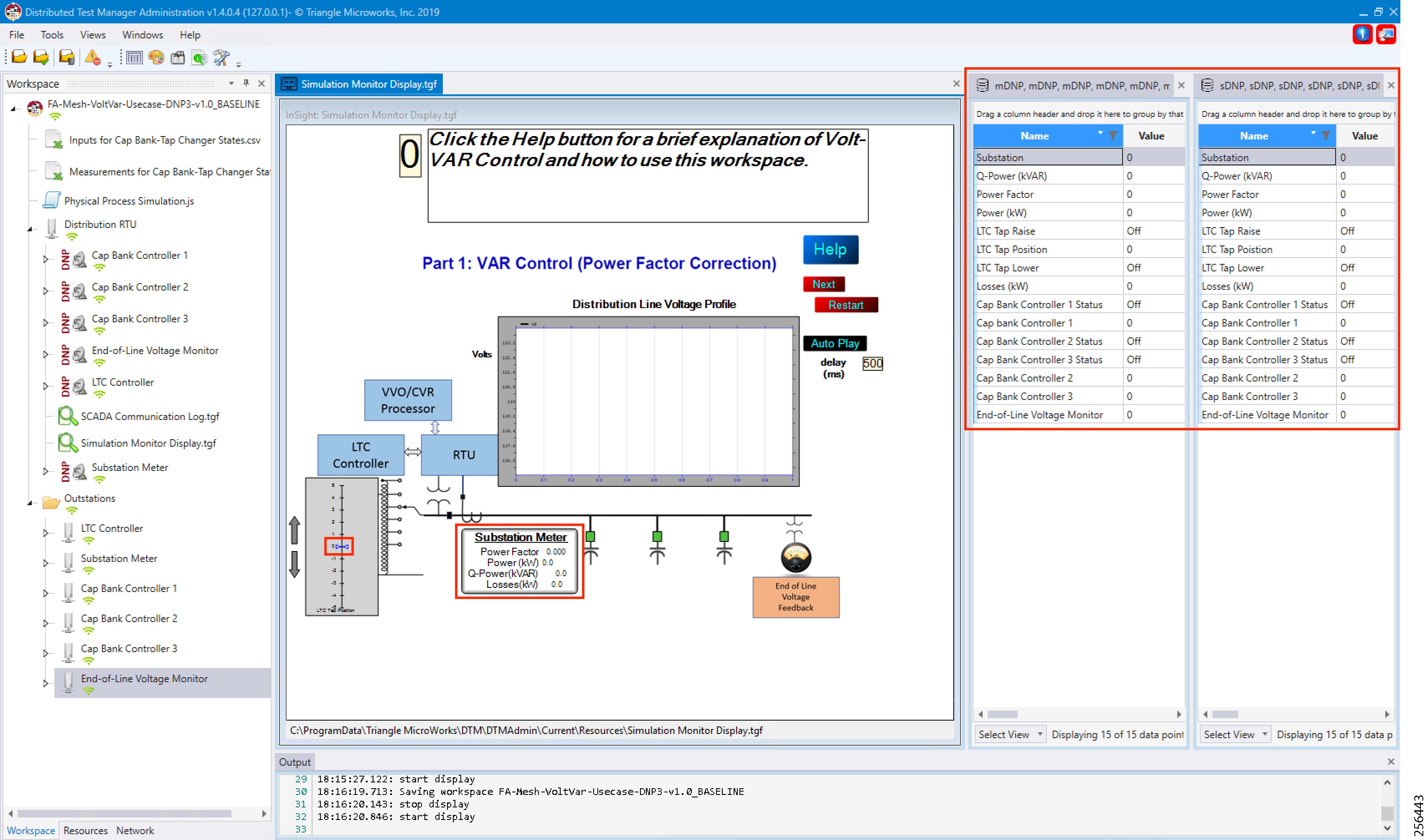
2.![]() Choose the correct network interface adapter in the Adapters tab.
Choose the correct network interface adapter in the Adapters tab.
Figure 123 DTM SCADA Control Center Adapter Configuration
The chosen network interface adapter would be used for communication between the DTM Master and the DTM Slave/Client PC.
Outstation General Configuration
Outstation or IEDs are configured in the DTM machine. There are five IEDs and one substation-monitoring device. All six devices are simulated in TMW's DTM application.
1.![]() Start the DTM service in the client machine with the role as Client, and the Master IP pointing to the SCADA Control Center.
Start the DTM service in the client machine with the role as Client, and the Master IP pointing to the SCADA Control Center.
Figure 124 DTM Outstation Role
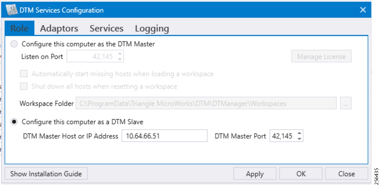
Note: When the DTM Master is loaded with the Volt/VAR workspace and the DTM service is started in the Client, then the outstation configuration is also automatically loaded into the client machine.
Outstation or IEDs data points per the following details.??
Figure 125 DTM Outstation Data Points
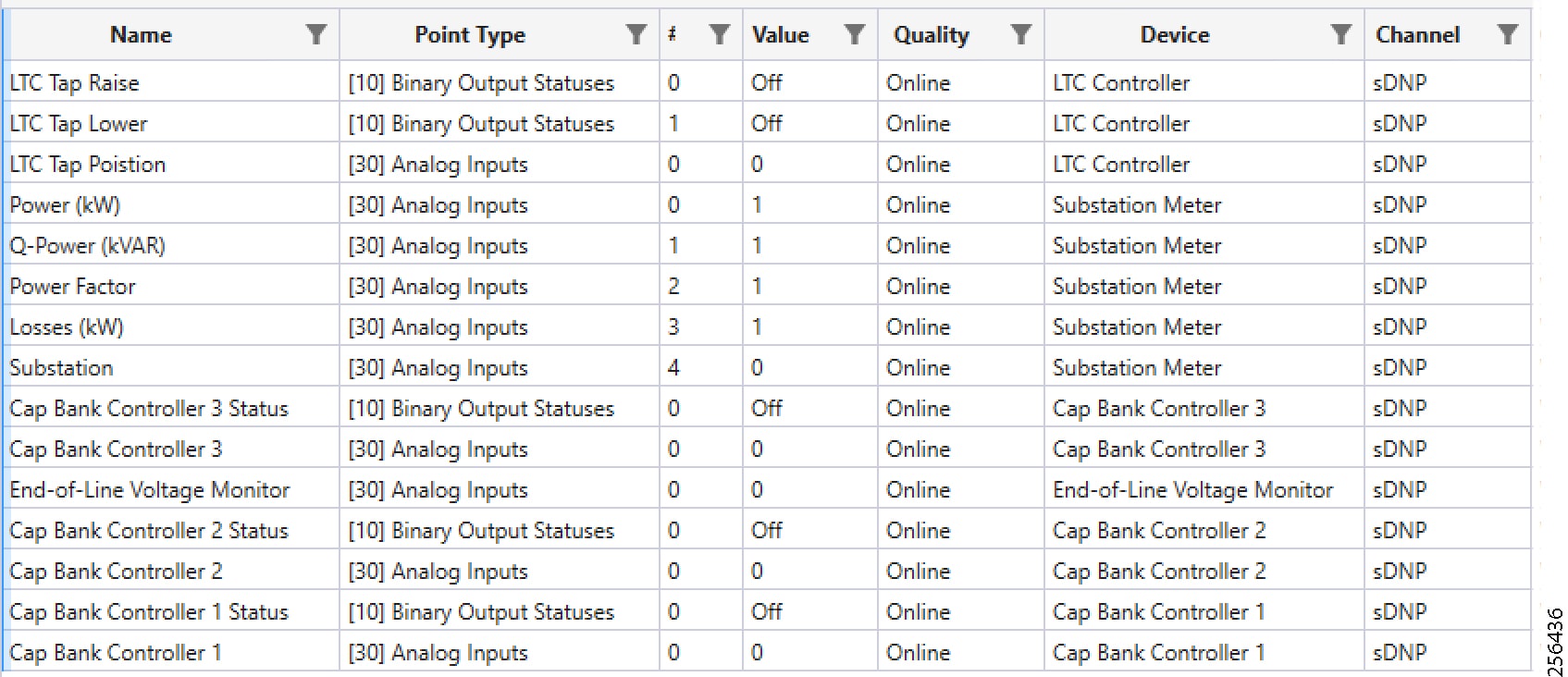
VAR Control (Power Factor Regulation)
Event Sequence Diagram
Use Case Steps
1.![]() Event class data poll to the following devices from RTU:
Event class data poll to the following devices from RTU:
–![]() Substation meter, poll Measured Value (Analog Input) registers.
Substation meter, poll Measured Value (Analog Input) registers.
–![]() All CBC(s), poll Measured Value (Analog Input), and Binary Output Statuses Point registers.
All CBC(s), poll Measured Value (Analog Input), and Binary Output Statuses Point registers.
–![]() End-of-Line voltage monitor, poll Measured Value (Analog Input) register.
End-of-Line voltage monitor, poll Measured Value (Analog Input) register.
2.![]() The Volt/VAR Optimization processor processes the data received from the devices and makes a control command decision based on the power factor calculation.
The Volt/VAR Optimization processor processes the data received from the devices and makes a control command decision based on the power factor calculation.
3.![]() The control command sent to RTU via SCADA to capacitor banks to close CBC N by writing in a Control Relay Output Block (CROB) command register in DNP3.
The control command sent to RTU via SCADA to capacitor banks to close CBC N by writing in a Control Relay Output Block (CROB) command register in DNP3.
4.![]() Event class data poll to the following devices from RTU:
Event class data poll to the following devices from RTU:
–![]() Substation meter, poll Measured Value (Analog Input) registers
Substation meter, poll Measured Value (Analog Input) registers
–![]() All CBC(s), poll Measured Value (Analog Input) and Binary Output Statuses Point registers
All CBC(s), poll Measured Value (Analog Input) and Binary Output Statuses Point registers
–![]() End-of-Line voltage monitor, poll Measured Value (Analog Input) register
End-of-Line voltage monitor, poll Measured Value (Analog Input) register
5.![]() The above steps are repeated to the CBC on the feeder line to maintain Power Factor value always close to value 1.
The above steps are repeated to the CBC on the feeder line to maintain Power Factor value always close to value 1.
VAR Control Use Case Simulation
1.![]() Import the Volt/VAR workspace, which is available in Appendix E: HER and CGR Configurations.
Import the Volt/VAR workspace, which is available in Appendix E: HER and CGR Configurations.
Figure 127 DTM Import Workspace
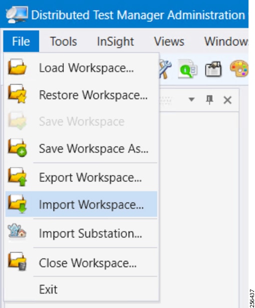
2.![]() Start all the host machines.
Start all the host machines.
Figure 128 DTM VVC Start All Hosts
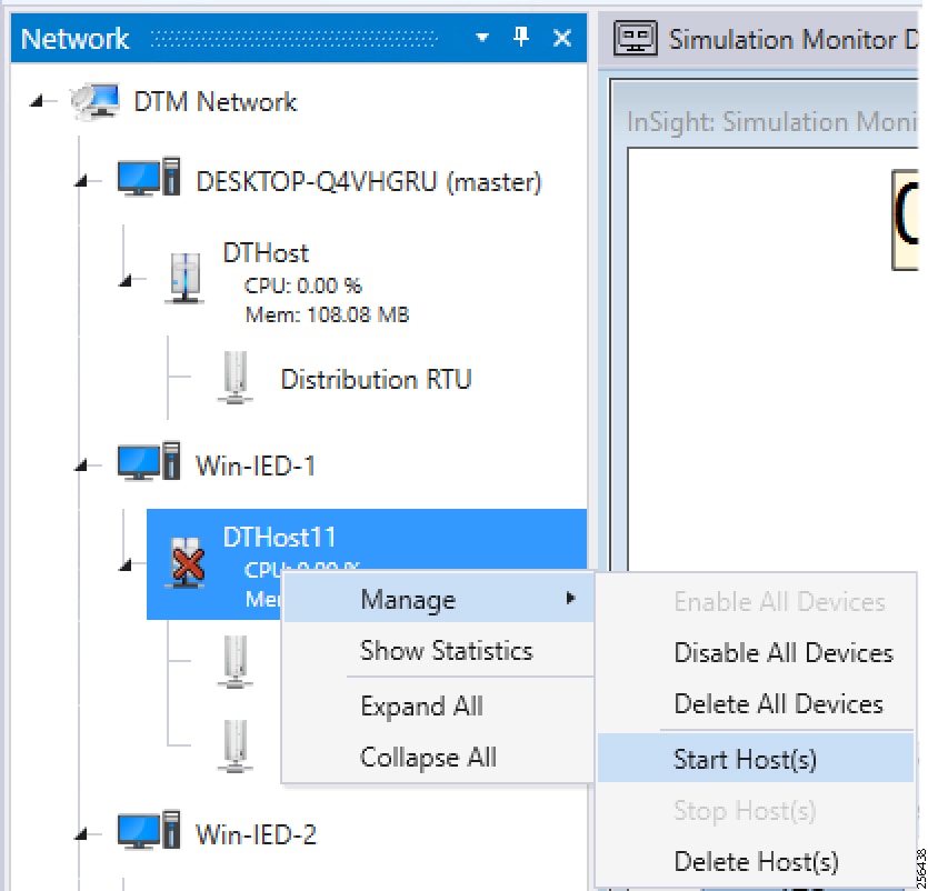
3.![]() Update the Remote IP address of all the RTU devices.
Update the Remote IP address of all the RTU devices.
Figure 129 DTM VVC Channel IP Config
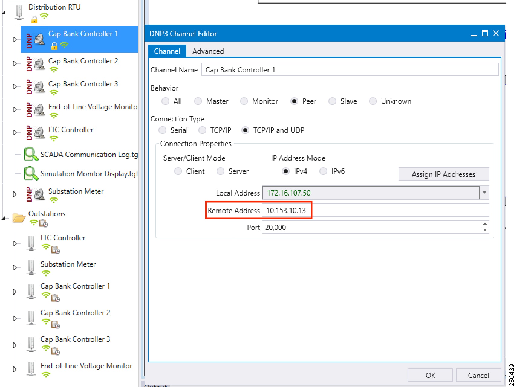
4.![]() Make sure all the channels are connected.
Make sure all the channels are connected.
Figure 130 DTM VVC Channel Status
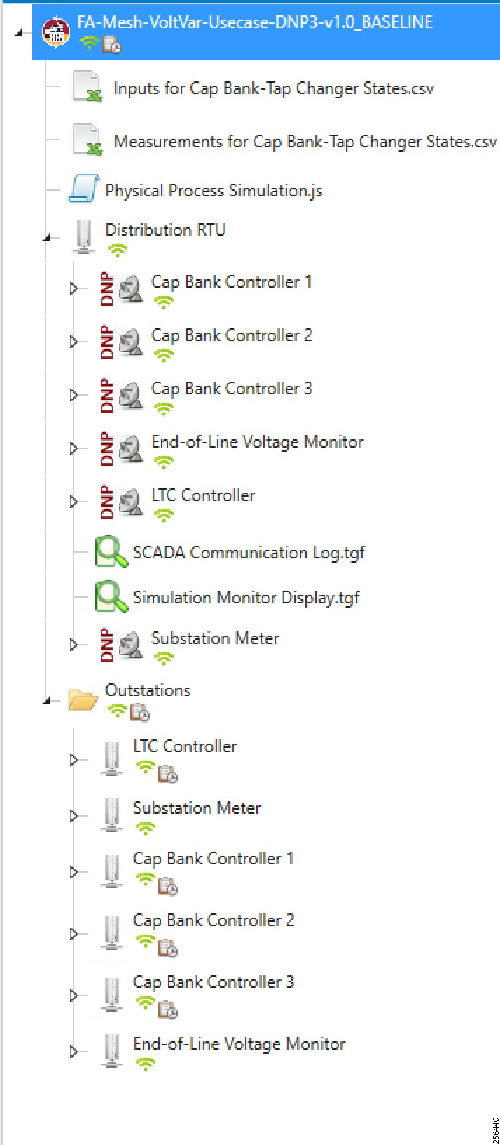
Figure 131 DTM VVC Start All Scripts
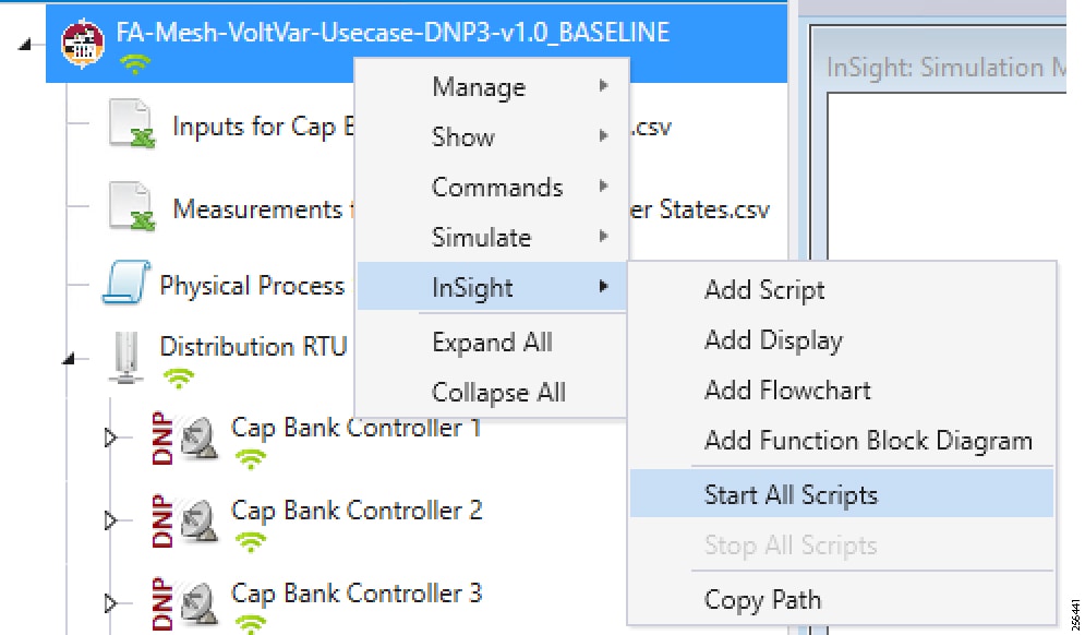
6.![]() Start the simulation by clicking Auto Play or Next.
Start the simulation by clicking Auto Play or Next.
Figure 132 DTM VVC Simulation Auto Playscript
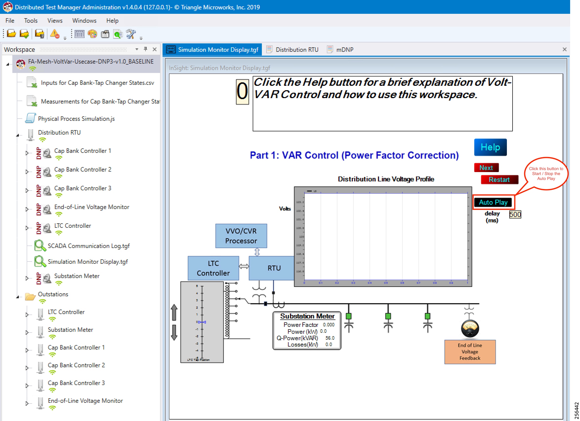
7.![]() Initialize the Outstation data points to default values.
Initialize the Outstation data points to default values.
Figure 133 DTM VVC Data Points Initialization
The substation meter data are initialized to zero before starting the VVC simulation.
8.![]() Data points from the two CSV files are applied appropriately by the simulation script to simulate the real time Volt/VAR events sequence.
Data points from the two CSV files are applied appropriately by the simulation script to simulate the real time Volt/VAR events sequence.
Figure 134 DTM VVC Event Class Polling
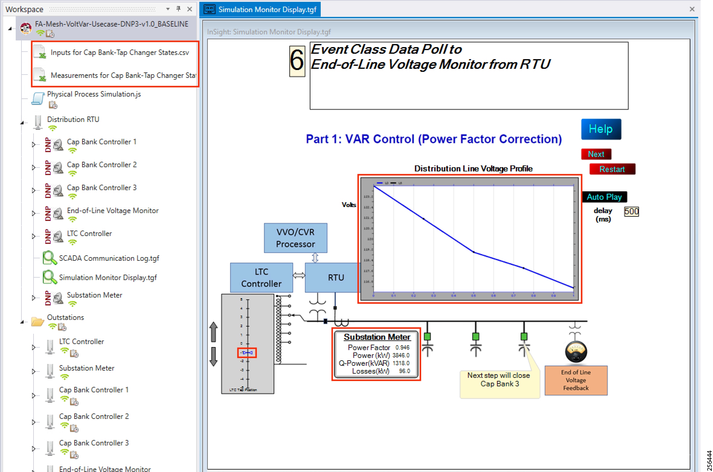
9.![]() Verify the voltage drops along the feeder line, as shown in Figure 134. Also, verify that substation meter values are not zero values.
Verify the voltage drops along the feeder line, as shown in Figure 134. Also, verify that substation meter values are not zero values.
10.![]() The Volt/VAR Optimization processor processes the data received from the devices and makes a control command decision based on the power factor calculation.
The Volt/VAR Optimization processor processes the data received from the devices and makes a control command decision based on the power factor calculation.
11.![]() The control command is sent to RTU via SCADA to capacitor banks to close the CBC3.
The control command is sent to RTU via SCADA to capacitor banks to close the CBC3.
Figure 135 DTM VVC CBC Closing
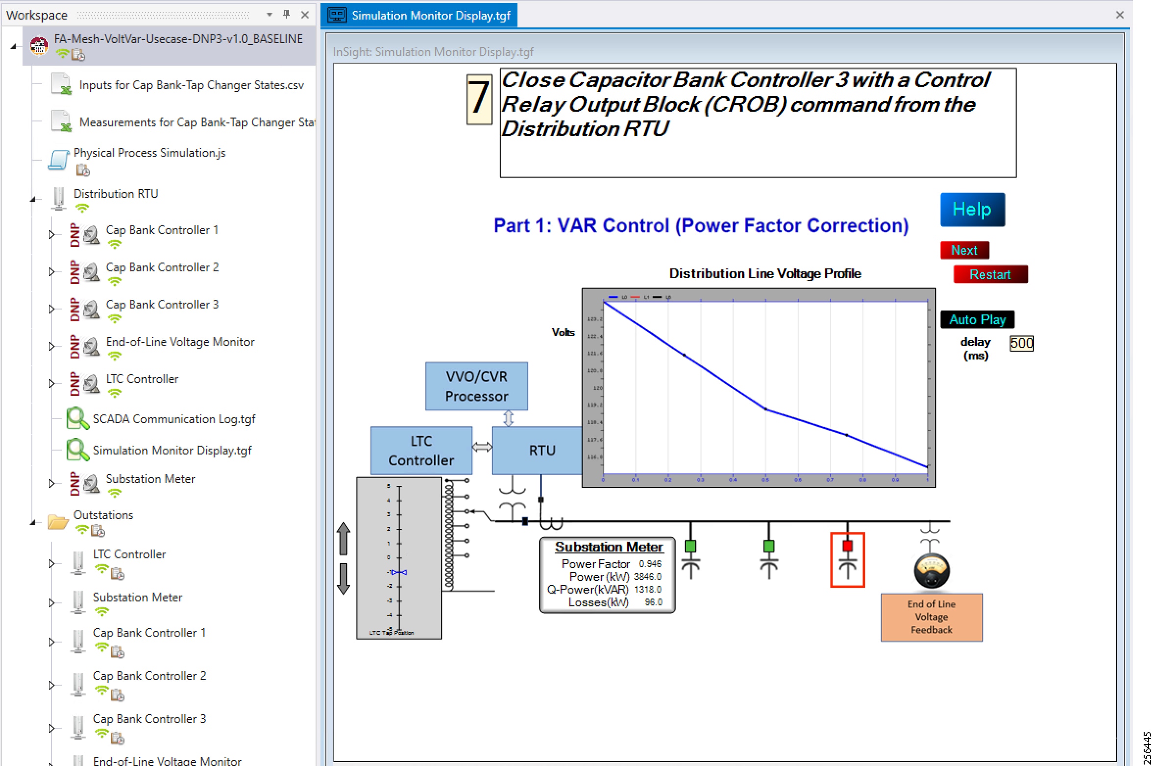
12.![]() Verify the CapBank is ON, as shown in Figure 135.
Verify the CapBank is ON, as shown in Figure 135.
13.![]() Event class data poll to the following devices from RTU:
Event class data poll to the following devices from RTU:
–![]() Substation meter, poll Measured Value (Analog Input) registers
Substation meter, poll Measured Value (Analog Input) registers
–![]() All CBC(s), poll Measured Value (Analog Input) and Binary Output Statuses Point registers
All CBC(s), poll Measured Value (Analog Input) and Binary Output Statuses Point registers
–![]() End-of-Line voltage monitor, poll Measured Value (Analog Input) register
End-of-Line voltage monitor, poll Measured Value (Analog Input) register
Figure 136 DTM VVC Event Class Polling with CBC3 Closed
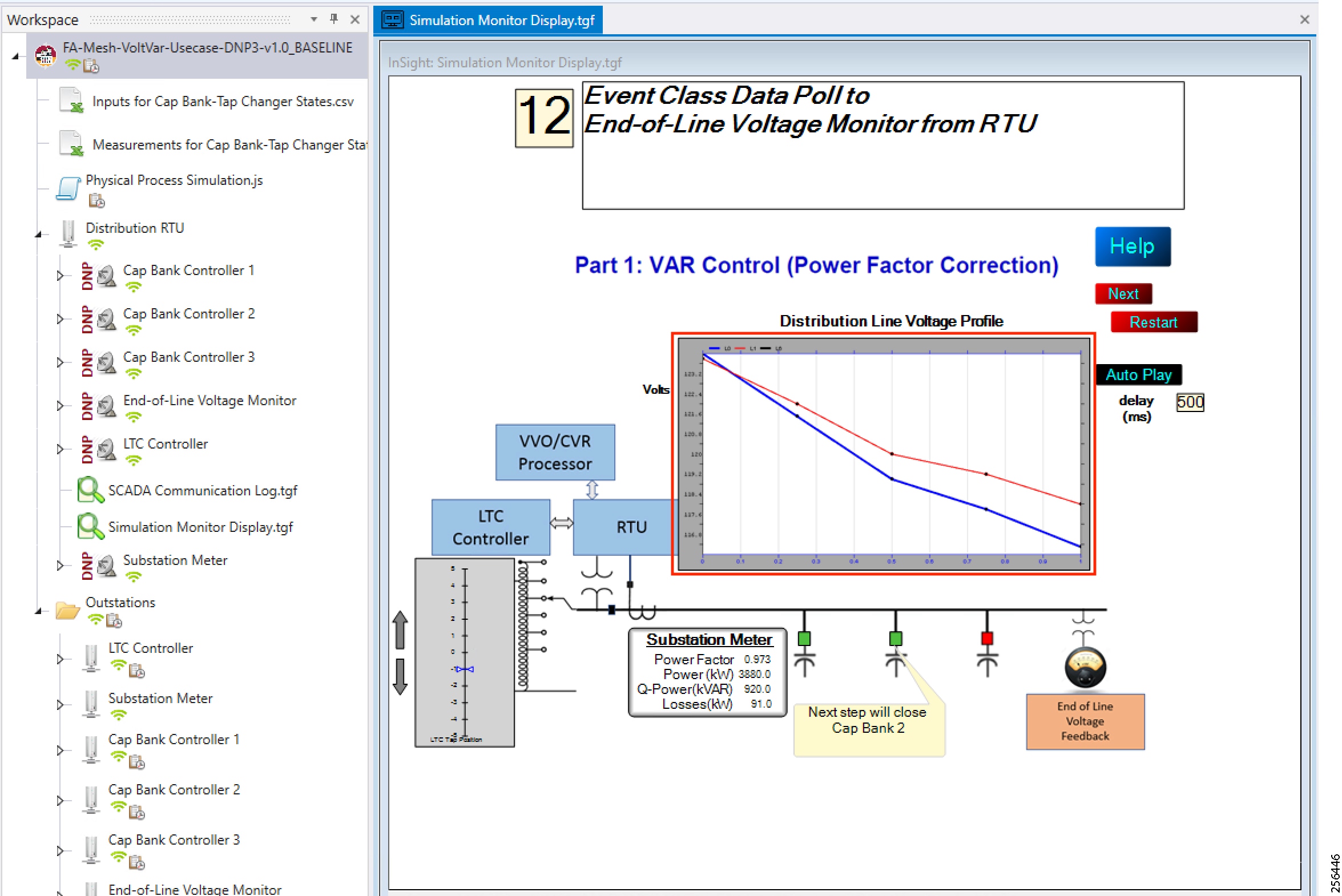
With CBC N On, voltage drop level decreased and power factor value increased.
14.![]() All the above steps are repeated to all the CBCs on the feeder line to maintain a Power Factor value always close to 1 at all the points in the feeder line.
All the above steps are repeated to all the CBCs on the feeder line to maintain a Power Factor value always close to 1 at all the points in the feeder line.
Figure 137 DTM VVC All 3 CBC Closed
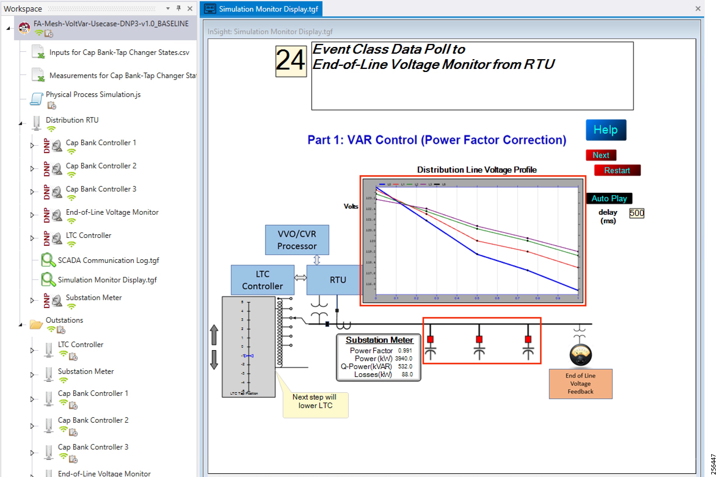
15.![]() Verify that all the CBCx are ON and power factor is increased to 99.1%.
Verify that all the CBCx are ON and power factor is increased to 99.1%.
Voltage Control (Conservation Voltage Reduction)
Conservation Voltage Reduction (CVR) can be achieved by moving the LTC up or down to maintain the Power Factor close to 1.
Event Sequence Diagram
Figure 138 Volt/VAR—CVR Sequence Diagram
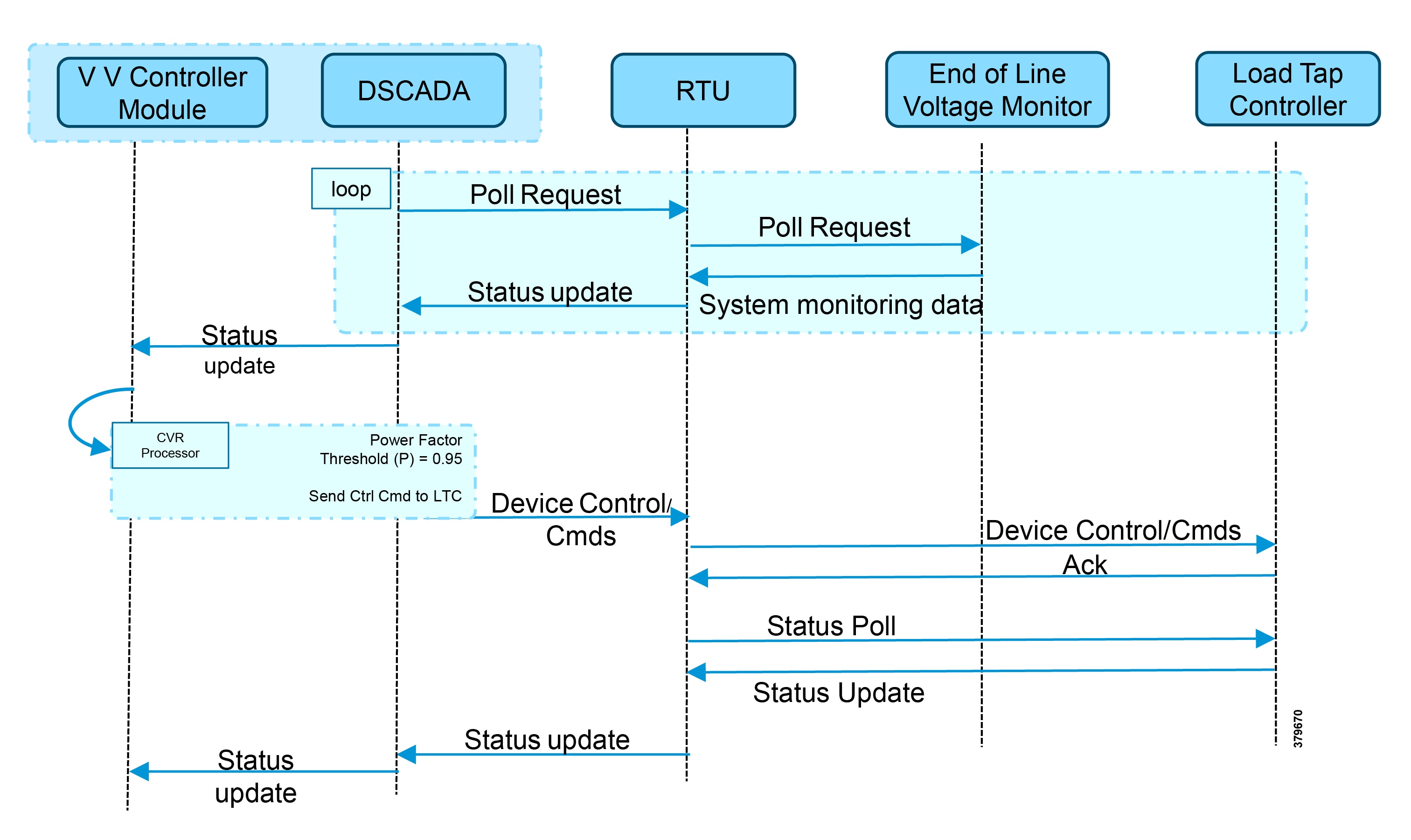
Use Case Steps
1.![]() Event class data poll to the following devices from RTU:
Event class data poll to the following devices from RTU:
–![]() Substation meter, poll Measured Value (Analog Input) registers
Substation meter, poll Measured Value (Analog Input) registers
–![]() All CBC(s), poll Measured Value (Analog Input) and Binary Output Statuses Point registers
All CBC(s), poll Measured Value (Analog Input) and Binary Output Statuses Point registers
–![]() End-of-Line voltage monitor, poll Measured Value (Analog Input) register
End-of-Line voltage monitor, poll Measured Value (Analog Input) register
2.![]() The Volt/VAR Optimization processor processes the data received from the devices and makes a control command decision based on the power factor calculation.
The Volt/VAR Optimization processor processes the data received from the devices and makes a control command decision based on the power factor calculation.
3.![]() Control command sent to RTU via SCADA to the LTC to lower/raise LTC.
Control command sent to RTU via SCADA to the LTC to lower/raise LTC.
4.![]() Event class data poll to the following devices from RTU:
Event class data poll to the following devices from RTU:
–![]() Substation meter, poll Measured Value (Analog Input) registers
Substation meter, poll Measured Value (Analog Input) registers
–![]() All CBC(s), poll Measured Value (Analog Input) and Binary Output Statuses Point registers
All CBC(s), poll Measured Value (Analog Input) and Binary Output Statuses Point registers
–![]() End-of-Line voltage monitor, poll Measured Value (Analog Input) register
End-of-Line voltage monitor, poll Measured Value (Analog Input) register
5.![]() All the above steps are repeated to maintain Power Factor value always close to value 1.
All the above steps are repeated to maintain Power Factor value always close to value 1.
CVR Use Case Simulation
1.![]() Follow Steps 1 to 8, under CVR use case simulation.??
Follow Steps 1 to 8, under CVR use case simulation.??
2.![]() The Volt/VAR Optimization processor processes the data received from the devices and makes a control command decision based on the power factor calculation.
The Volt/VAR Optimization processor processes the data received from the devices and makes a control command decision based on the power factor calculation.
3.![]() Control command sent to RTU via SCADA to the LTC to lower/raise the LTC by writing in a command register. The LTC is lowered to -2, by the script.
Control command sent to RTU via SCADA to the LTC to lower/raise the LTC by writing in a command register. The LTC is lowered to -2, by the script.
Figure 139 DTM CVR LTC Lowering
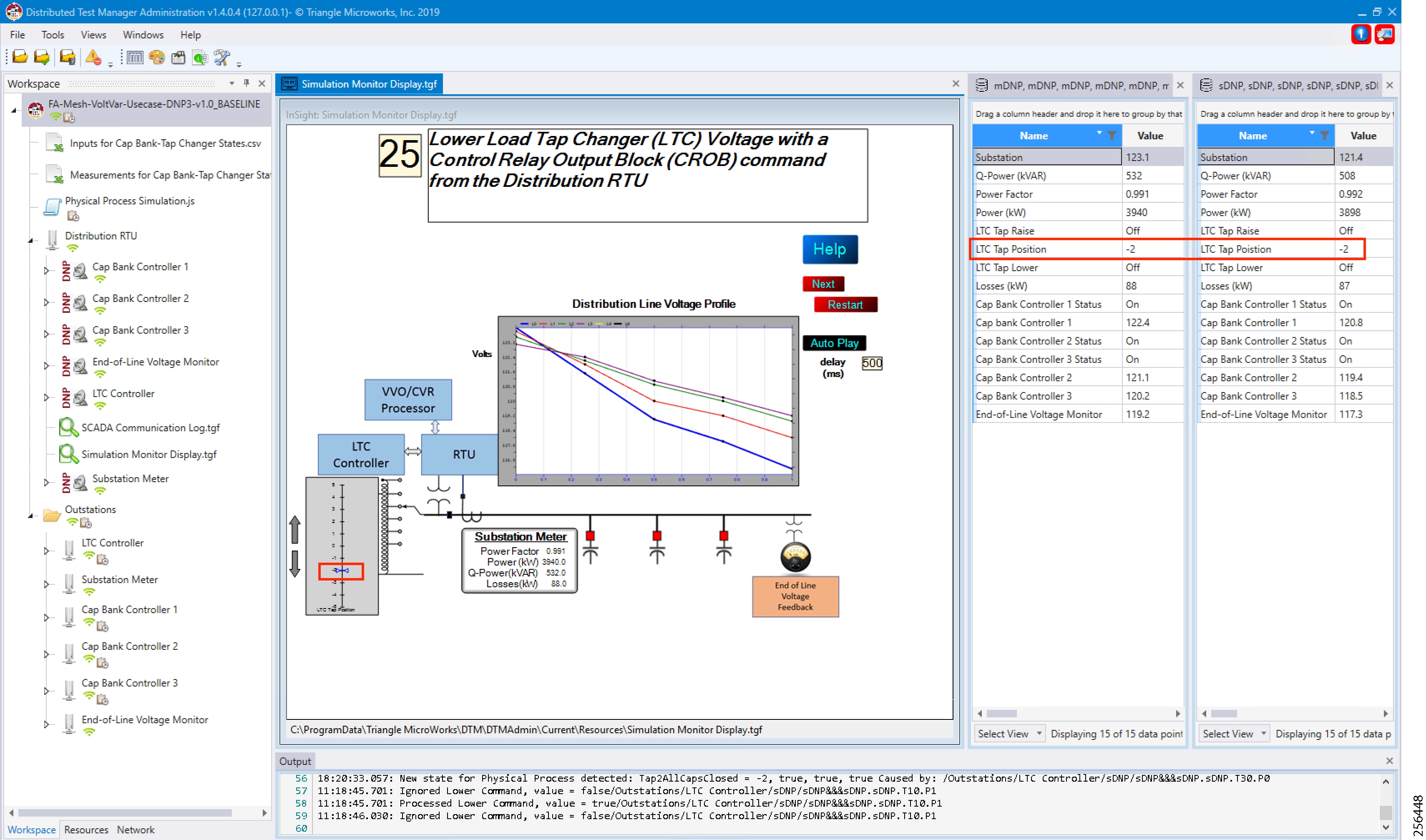
4.![]() Event class data poll to the following devices from RTU:
Event class data poll to the following devices from RTU:
–![]() Substation meter, poll Measured Value (Analog Input) registers
Substation meter, poll Measured Value (Analog Input) registers
–![]() All CBC(s), poll Measured Value (Analog Input) and Binary Output Statuses Point registers
All CBC(s), poll Measured Value (Analog Input) and Binary Output Statuses Point registers
–![]() End-of-Line voltage monitor, poll Measured Value (Analog Input) register
End-of-Line voltage monitor, poll Measured Value (Analog Input) register
Figure 140 DTM CVR Event Class Polling
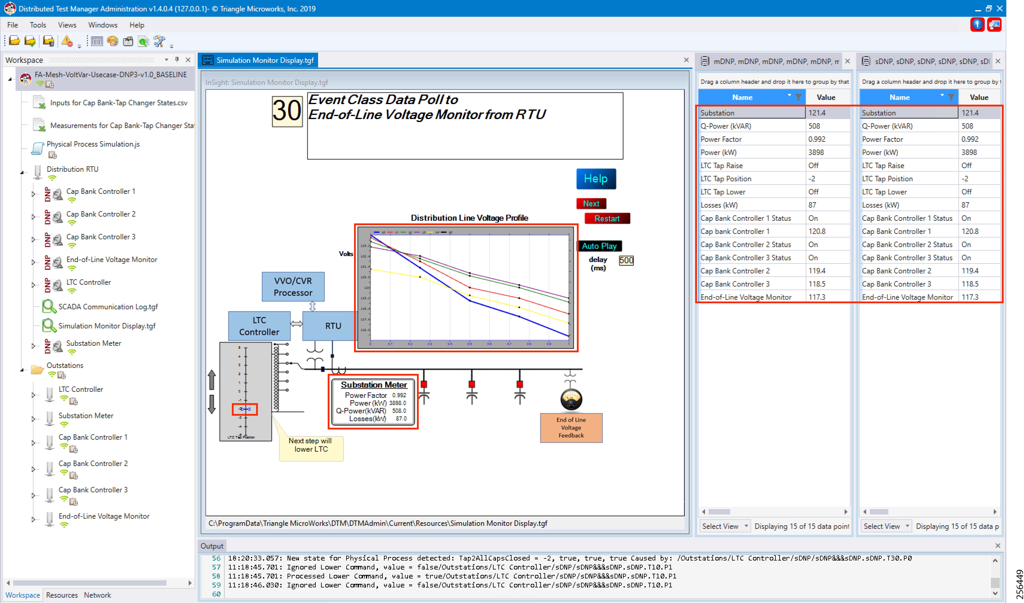
5.![]() Verify that the data from feeder devices (extreme right window) are updated in SCADA control center and that graphs and substation meter values are displayed.
Verify that the data from feeder devices (extreme right window) are updated in SCADA control center and that graphs and substation meter values are displayed.
All the above steps are repeated to maintain Power Factor value always close to 1 at all points in the feeder line.
Figure 141 DTM CVR End of Simulation
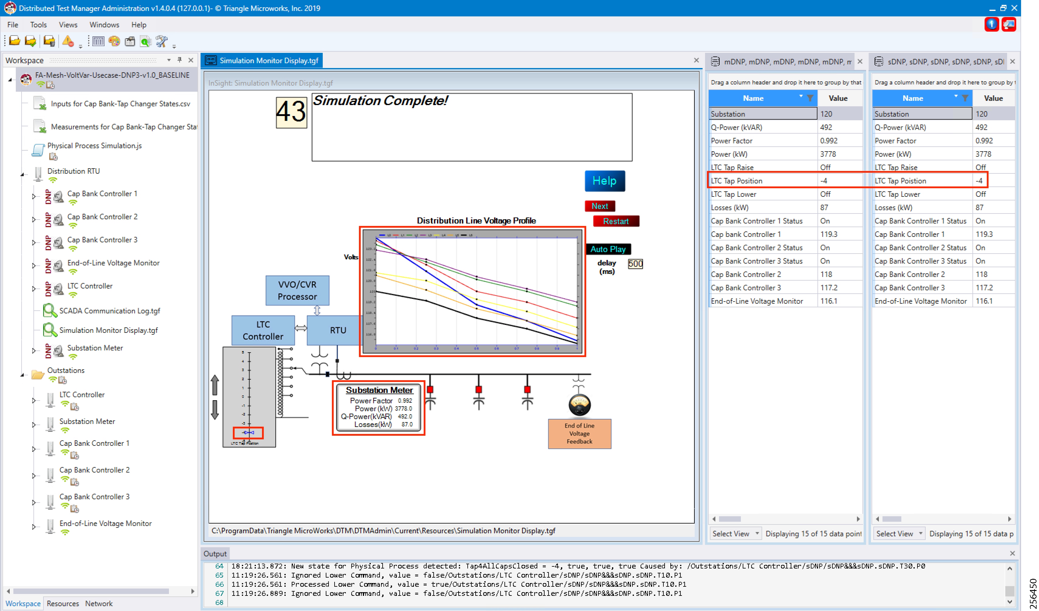
6.![]() Verify that the outstation device data are updated to SCADA Control Center and the Power Factor values to 1; in the above example, the Power Factor value is 0.992(99.2%).
Verify that the outstation device data are updated to SCADA Control Center and the Power Factor values to 1; in the above example, the Power Factor value is 0.992(99.2%).
Distribution Automation Use Case Scenario – FLISR
Fault Location, Isolation, and Service Restoration (FLISR)
Fault Location, Isolation, and Service Restoration (FLISR) is the process for dealing with fault conditions on the electrical grid. When a fault occurs in a section of the grid, first identify fault location and isolate the smallest possible section affected by the fault. Then restore the power to larger possible section of the grid.
The goal of the FLISR to minimize the fault affected area with very short turnaround time by identifying the fault location, isolating the fault section, and restoring the power to the remaining section of the grid within a short turnaround time.
Note: Prerequisite for executing the FLISR use case is stable CR mesh in which two-way communication between Headend to DA gateway IR510 device. Refer section “Solution Network Topology and Addressing for FLISR validation” in this document.
Schweitzer Engineering Laboratories (SEL) Devices
SEL FLISR products works reliably with the Cisco Resilient Mesh network, in aspects of tripping time, data alignment, service restoration and operation consistency on ISM 902-928MHz and IEEE802.15.4g/e standard using OFDM modulation with a physical data rate up to 1.2 Mbps can support the performance requirements of FLISR application.
This guide captures the configuration and simulation of SEL FLISR application on Cisco Resilient Mesh with physical data rate of 800kbps, over a variety of topologies and places in the network.
All SEL devices and application involved in simulating the FLISR use case are listed in the below table.
|
|
|
|
|
|
|
|
|
|
|
|
Urban topology
Electrical line diagram
The one-line diagram for the urban topology, including four feeders that were interconnected between them with reclosers in Normal Open state (green box) is shown in the figure below.
Figure 142 FLISR Urban electrical line diagram
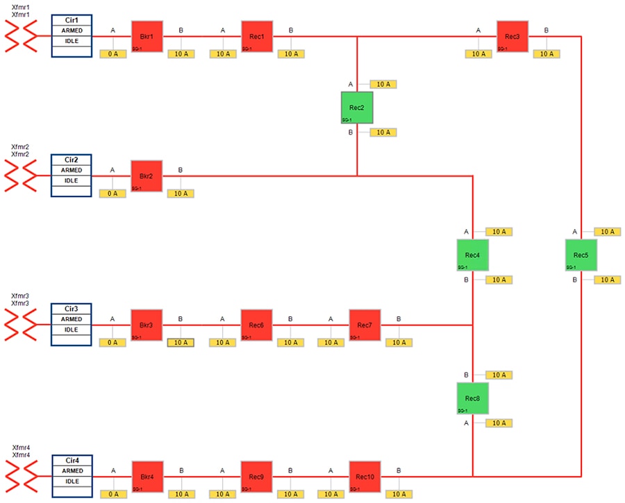
The legend for the FLISR electrical line diagram is below.
Figure 143 FLISR electrical line diagram legend
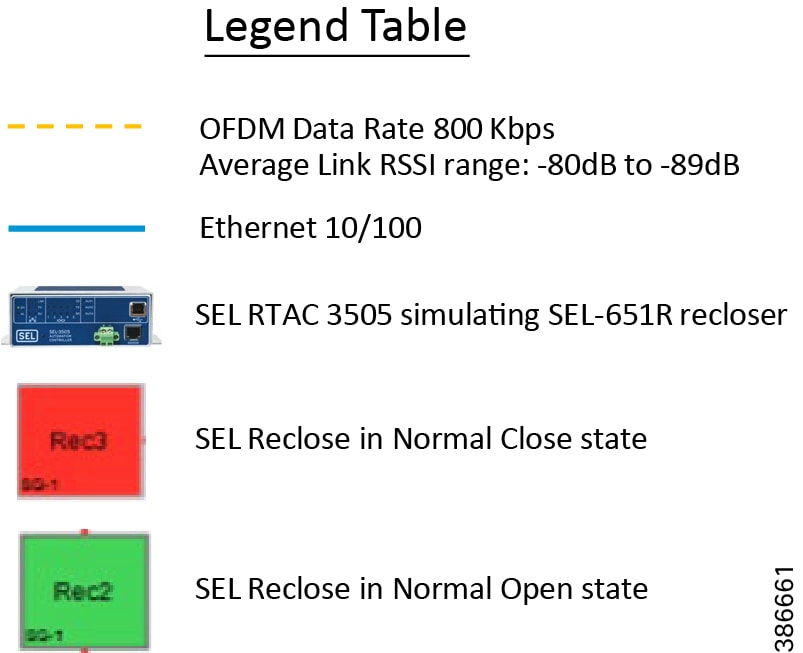
Each feeder capacity was designed for 540A and it was sourced from an independent transformer. Substation breakers located at the beginning of each feeder offered protection for the entire distribution line. Different loads were placed on the feeders so that the SEL FLISR controller can select the most optimal feeder as the next power source during an outage and service restoration phase.
Aggregate topology lab setup
Below topology captures the 1 to 1 mapping of SEL recloser devices to Cisco’s IR510 devices. The controller device is located in the Primary control center. CR Mesh is aggregated at the Field Area Network aggregator (using CGR1000 series of router) which could be located in the substation. The communication between substation and control center could happen over public/private WAN. The SEL device is positioned behind IR510 and connected using Ethernet.
Figure 144 FLISR Aggregate lab topology
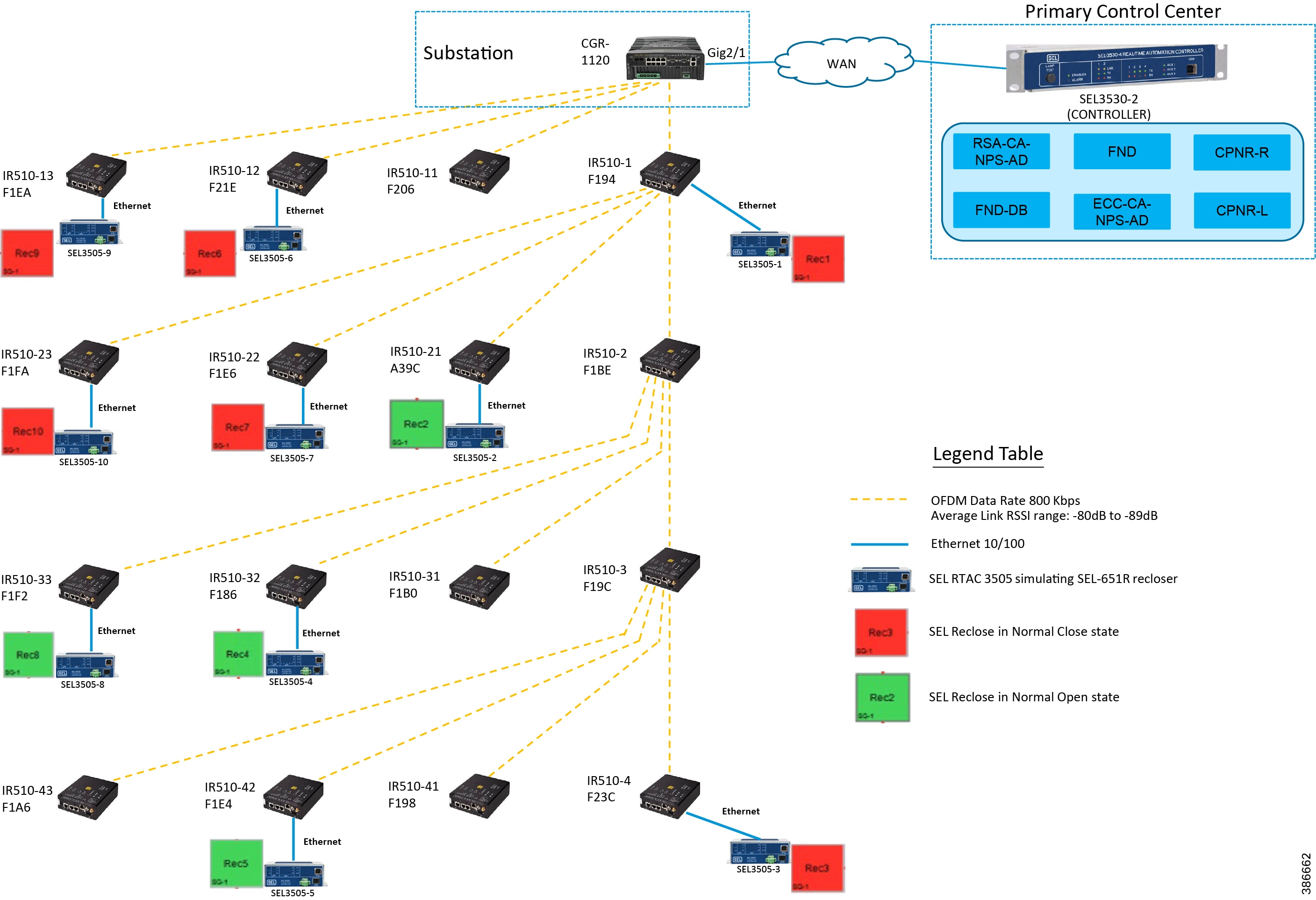
Table 24 FLISR Urban Topology Components
Rural topology
Electrical line diagram
This section explains the linear CR mesh deployment scenario, the below electrical diagram depicts the linear deployment scenarios, which is simulated over 10 SEL reclosers between two substations where the recloser Rec6 was in Normal Open state (NO) while all other reclosers were in Normal Close state (NC).
Figure 145 FLISR Rural electrical line diagram
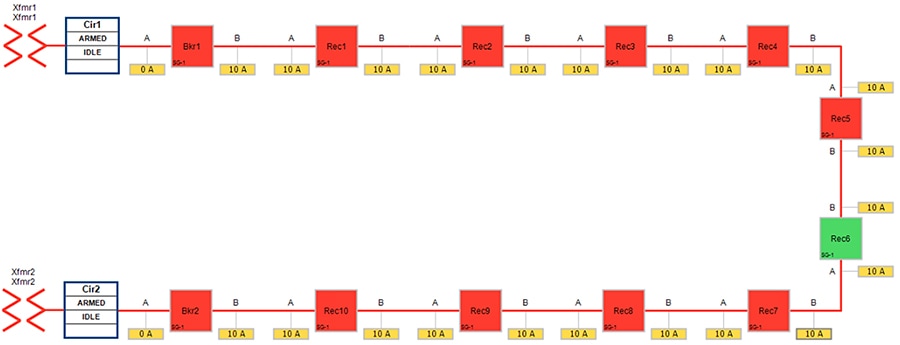
Linear topology lab setup
The SEL reclosers were still connected via the Ethernet to each Cisco IR510 and all the IR510 devices are connected in linear CR mesh with following configuration.
Figure 146 FLISR linear topology lab diagram
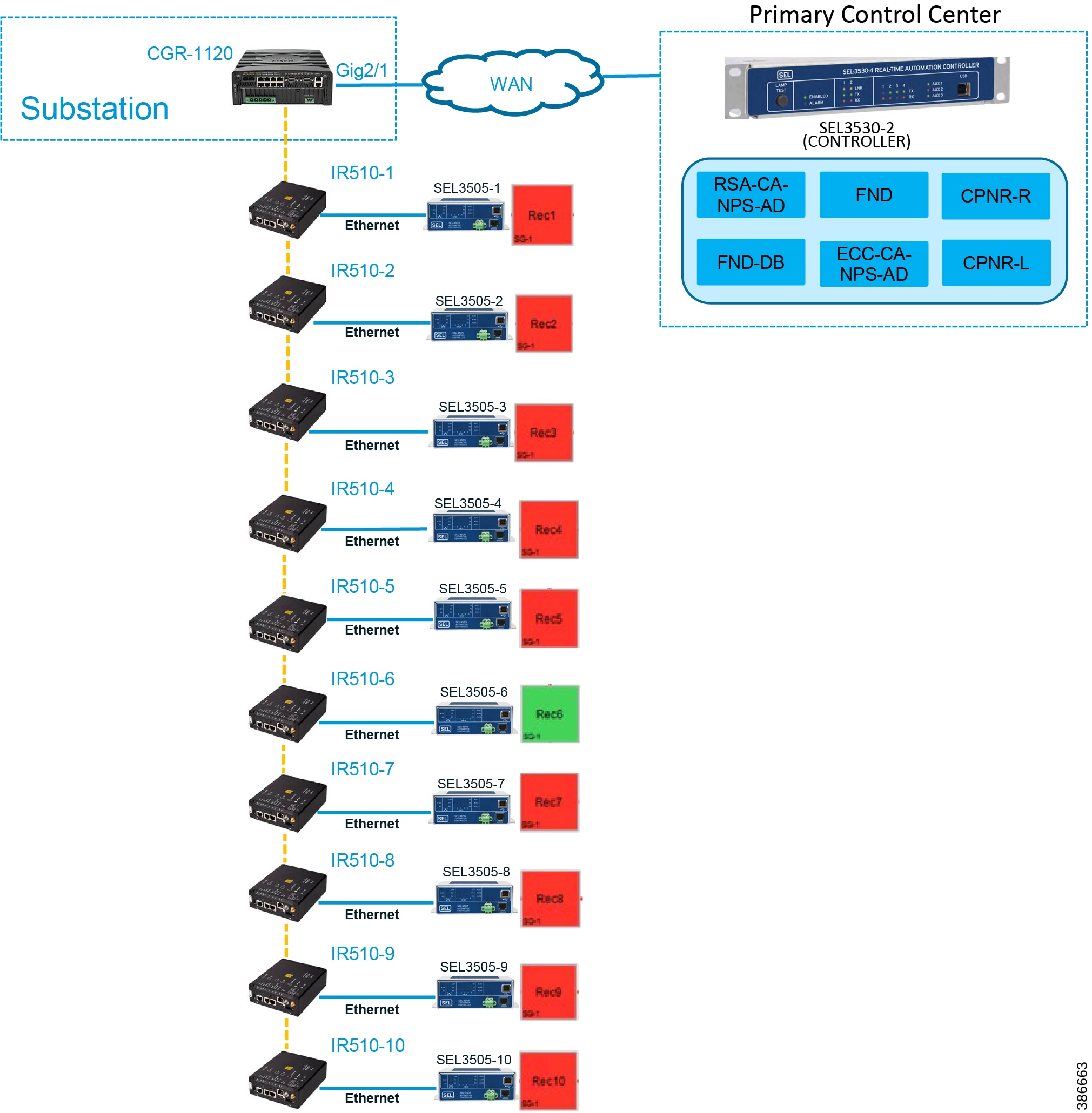
Refer to Linear Mesh lab topology for FLISR section of this document for more details about this lab topology.
FLISR simulation network
FLISR simulation network is used for transporting FLISR events simulation traffic SEL RTAC 3505 and SEL RTAC 3530, which act as a DA Controller.
SEL RTAC 3530 was installed in the Control Center. The FLISR controller (DA FLISR Controller) was configured to communicate with each SEL RTAC3505 and work as a system to perform Service Restoration also known as Circuit Reconfiguration during a grid outage event.
A second SEL RTAC3530 (DA Simulator) was used to simulate different grid conditions and to create different failures over a dedicated network called Simulator Ethernet Network, which is depicted as red line. A laptop running the SEL AcSELerator software is used for SEL device configuration, FLISR topology monitoring and fault simulation.
The red line in below figure represents the Ethernet network, which is used for out-of-band communication for FLISR events simulation. The OT traffic of actual FLISR events are communicated through in-band via Cisco CR mesh to DAC and vice versa. All in-band communication is via Cisco CR mesh and FLISR events simulation uses out-of-band communication via Ethernet.
Figure 147 FLISR simulation network
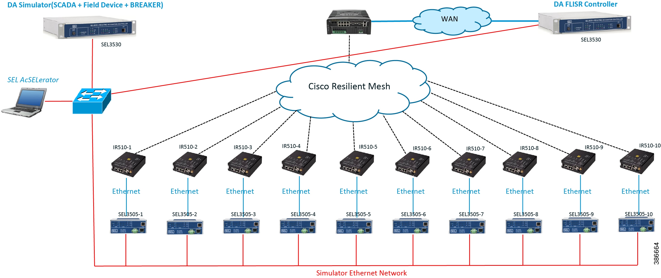
The SEL RTAC 3505 controllers are used in our lab validation instead of real SEL-651R reclosure electrical device. The SEL 651R device functionality and features are emulated in SEL RTAC-3505 devices to generate typical FLISR events and OT communication traffic in our lab environment, without connecting to actual electrical power grid.
FLISR Event Sequence Diagram
Figure 148 FLISR event sequence diagram
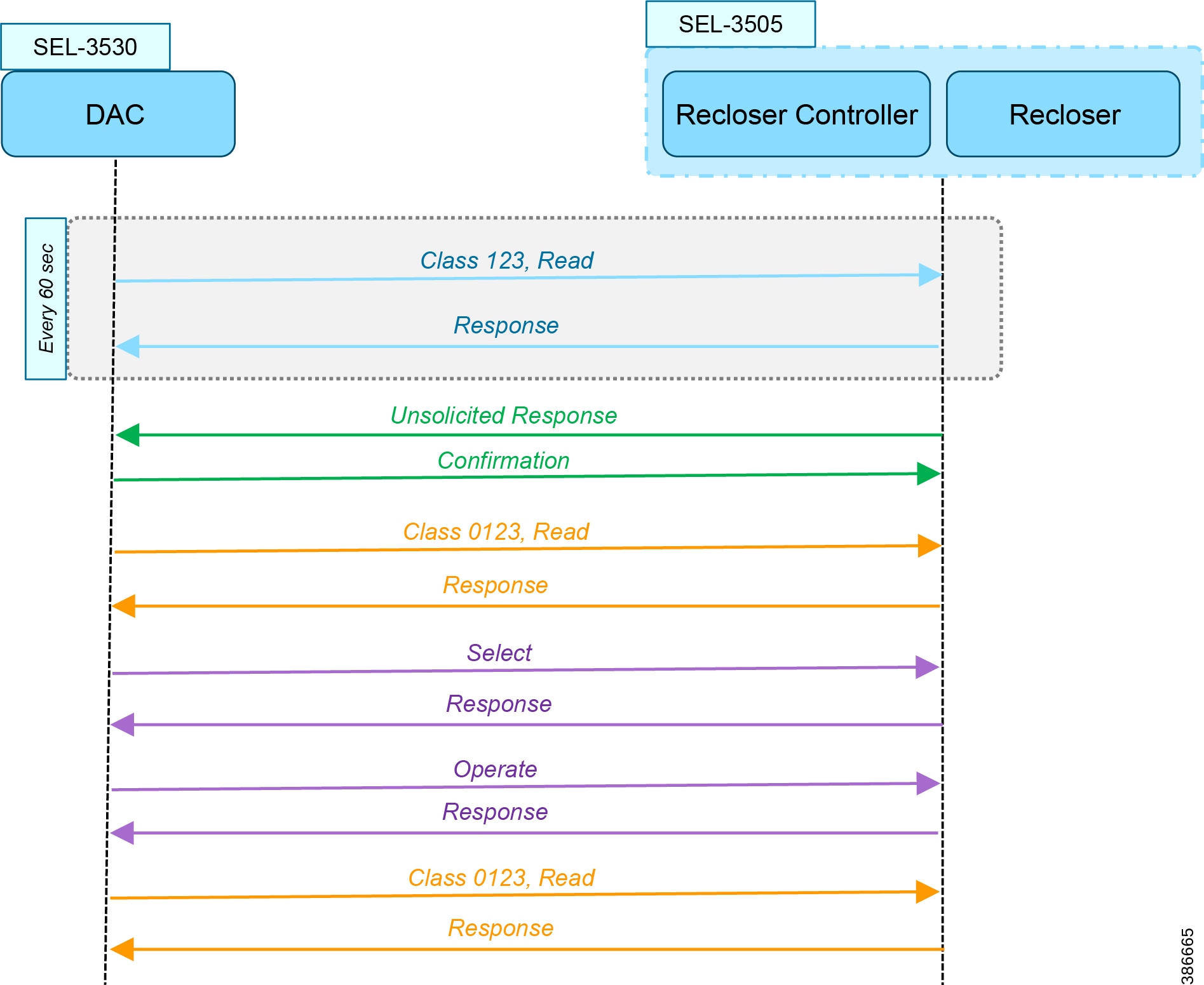
Use Case Steps
1.![]() Class 123 Read happens every 60 seconds. For each Class read, there is a Response from IED. There is also Class0123 periodic poll, but with a longer duration than the class 123. This Class 0123 polling may or may not fall within the time duration of actual FLISR event sequence.
Class 123 Read happens every 60 seconds. For each Class read, there is a Response from IED. There is also Class0123 periodic poll, but with a longer duration than the class 123. This Class 0123 polling may or may not fall within the time duration of actual FLISR event sequence.
2.![]() Unsolicited Response happens whenever any change in value of DNP3 point list in IED. For each Unsolicited Response from IED, there is a Confirmation message from DAC.
Unsolicited Response happens whenever any change in value of DNP3 point list in IED. For each Unsolicited Response from IED, there is a Confirmation message from DAC.
3.![]() On receiving the Unsolicited Response from IED, the DAC sends a Control Command Select to selective recloser(s) to block for sending the actual control command. For each Select command, there is a Response from IED/Recloser.
On receiving the Unsolicited Response from IED, the DAC sends a Control Command Select to selective recloser(s) to block for sending the actual control command. For each Select command, there is a Response from IED/Recloser.
4.![]() After successful Select command, the DAC sends the Control Command Operate to selective recloser(s) to Open/Close. For each Operate command, there is a Response from IED/Recloser.
After successful Select command, the DAC sends the Control Command Operate to selective recloser(s) to Open/Close. For each Operate command, there is a Response from IED/Recloser.
5.![]() After successful control command operation, confirmation of IED/Recloser status shall be updated by Unsolicited Response and overall grid status is updated by another Class 0123 Read operation. For each Class Read, there is a Response from IED/Recloser.
After successful control command operation, confirmation of IED/Recloser status shall be updated by Unsolicited Response and overall grid status is updated by another Class 0123 Read operation. For each Class Read, there is a Response from IED/Recloser.
FLISR USE CASE SIMULATION using SEL AcSELerator application
This section describes the validation efforts conducted indoor for testing Fault Location, Isolation, Service Restoration (FLISR) using Schweitzer Engineering Laboratories (SEL) equipment. SEL is one of the major utility grid equipment and DA solution vendor in North America.
SEL RTAC 3530/3505 initial configurations Schweitzer Electric Laboratories (SEL) has a comprehensive solution for the DA FLISR application that can be deployed in distributed or centralized architectures. The solution uses a controller device to provide advanced restoration capabilities that can be located in the distribution substation or control center. Combined with Cisco Resilient Mesh communication infrastructure the FLISR application can operate in fully automatic mode.
The SEL reclosers connect to the Cisco Resilient Mesh Industrial Routers (IR510) via ethernet port.
The SEL FLISR was tested in a Centralized configuration where a SEL RTAC 3530 was installed in the Control Center. The FLISR controller (DA FLISR Controller) was configured to communicate with each SEL RTAC3505 and to work as a system to perform Service Restoration also knows as Circuit Reconfiguration during a grid outage event. A second SEL RTAC3530 (DA Simulator) was used to simulate different grid conditions and to create different failures over a dedicated network called Simulator Ethernet Network. A laptop running the SEL AcSELerator software was used for SEL device configuration, FLISR topology monitoring and fault insertion.
Refer to the Design document for more information about the FLISR architecture and infrastructure setup.
Note: For additional information on the SEL RTAC product family, visit: https://selinc.com/products/3530/
When SEL devices are not available FLISR use case shall be simulated using the TMW DTM application, refer to Appendix F: FLISR Simulation using DTM for more detail.
SEL RTAC Ethernet Interface Configuration
1.![]() Use the included USB cable to connect your computer to the type-B USB port on the front of the RTAC.
Use the included USB cable to connect your computer to the type-B USB port on the front of the RTAC.
2.![]() Follow the prompts to install the USB driver. The USB driver provides an Ethernet connection to the RTAC.
Follow the prompts to install the USB driver. The USB driver provides an Ethernet connection to the RTAC.
3.![]() Type the USB default IP address https://172.29.131.1 to access the secure RTAC web interface using any web browser.
Type the USB default IP address https://172.29.131.1 to access the secure RTAC web interface using any web browser.
Figure 149 SEL RTAC Web page login
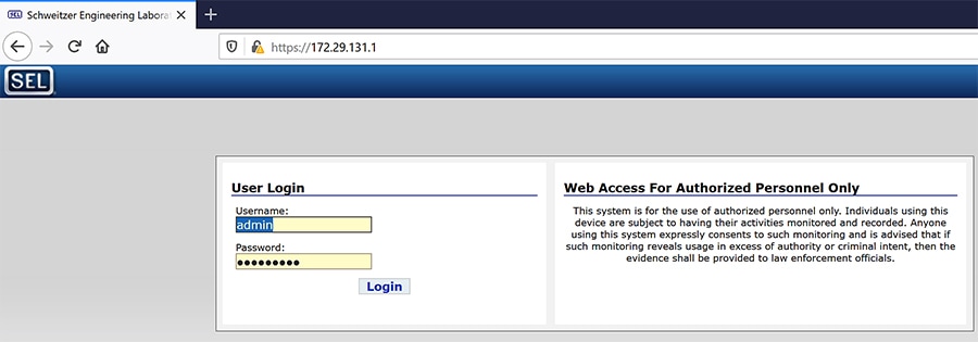
If accessing the web page of the device for the first time, the web page prompts the user to create username and password. After the username and password are created, the same credentials can be used to access the web page on subsequent visits.
4.![]() Click the Interface Under Network tab on the left panel.
Click the Interface Under Network tab on the left panel.
Figure 150 SEL RTAC Ethernet interface details
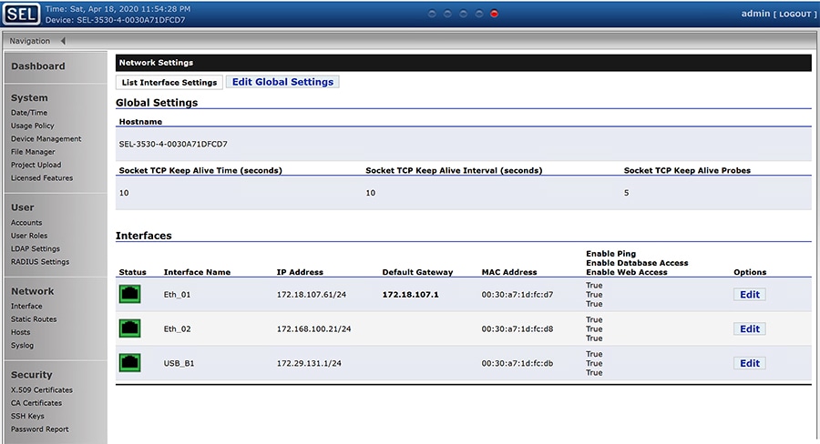
There are three ethernet interfaces available in the SEL-RTAC device, one is used for USB console port, which the user using it to configure the device via the web page. On the other two ethernet ports, Eth1 is used to connect to IR510 and Eth2 is connected to the FLISR simulation network.
5.![]() Click on Edit button against the Eth1 interface, to edit the network information for that interface.
Click on Edit button against the Eth1 interface, to edit the network information for that interface.
6.![]() Edit the first interface with Control Center IP/ IED IP.
Edit the first interface with Control Center IP/ IED IP.
Figure 151 SEL RTAC IPv4 settings for CR Mesh
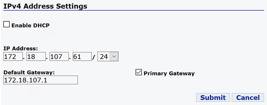
Configure the Control Center IP for the SEL RTAC 3530 device, which acts are a DAC Controller.
For the other SEL RTAC 3530 device which acts as a Simulator, no configuration is required.
For all SEL RTAC 3505 devices, configure this interface with CR Mesh IP network address and gateway as the IR510 interface IP.
7.![]() Edit the second interface with FLISR simulation IP subnets.
Edit the second interface with FLISR simulation IP subnets.
Figure 152 SEL RTAC IPv4 settings for FLISR simulation
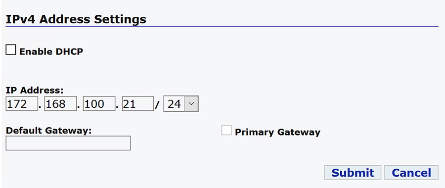
Configure the second Ethernet interface Eth2 with the FLISR simulator network interface for all the SEL RTAC devices.
FLISR Project setup
SEL developed a comprehensive FLISR projects for the two topologies, Urban and Rural topologies. SEL provides set of project files for both these topologies, which needs to be pushed to the SEL RTAC devices before executing the FLISR use case simulation. The details and usage of these project files are listed below in the table
Table 25 SEL Project files details
These project files shall be provided by the SEL team.
User should push all Recloser files to all the SEL RTAC devices, the Recloser project is same for both the topologies. But the DAC and Simulator file are loaded based on the topologies under testing.
To push the project file to the SEL RTAC devices, follow the steps described in the Simulation Go Online section.
1.![]() AcSELerator Application login.
AcSELerator Application login.
Figure 153 SEL AcSELerator application login
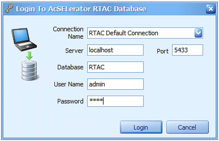
By default, the username is admin and password shall be shared by SEL team.
2.![]() To import FLISR projects into the application, click on SEL icon and select Import.
To import FLISR projects into the application, click on SEL icon and select Import.
Figure 154 FLISR Project Import menu
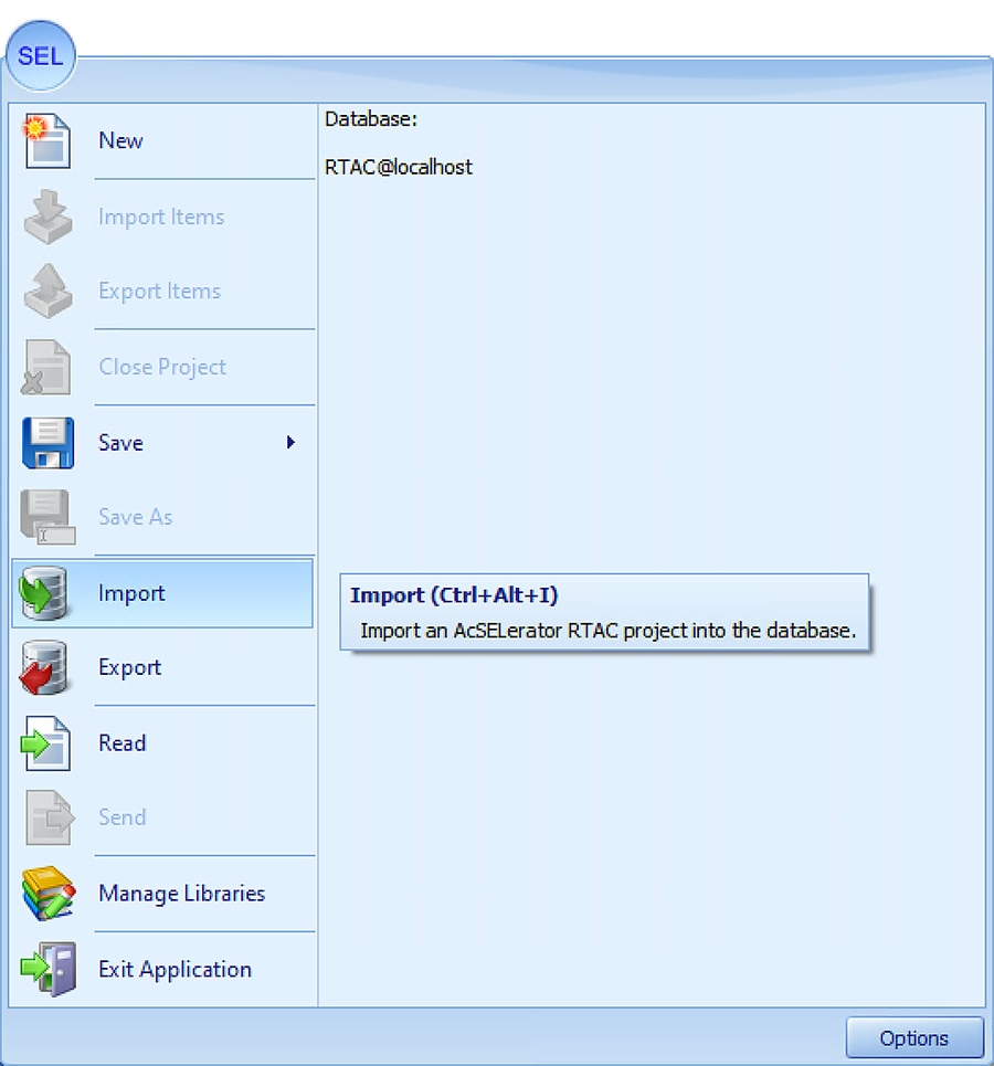
3.![]() Choose SEL project files from the local machine to import into the application. Multiple files can be selected and imported all at once.
Choose SEL project files from the local machine to import into the application. Multiple files can be selected and imported all at once.
Figure 155 SEL FLISR project import files
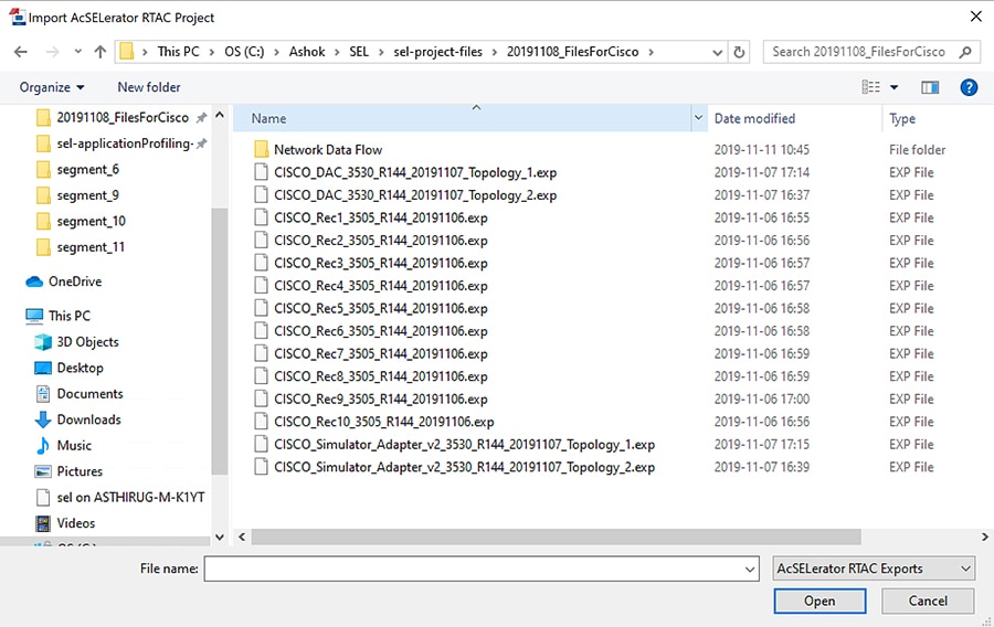
4.![]() To import DAC Libraries into application, click on SEL icon and then select Manage Libraries.
To import DAC Libraries into application, click on SEL icon and then select Manage Libraries.
Figure 156 FLISR DAC Manage Library menu item
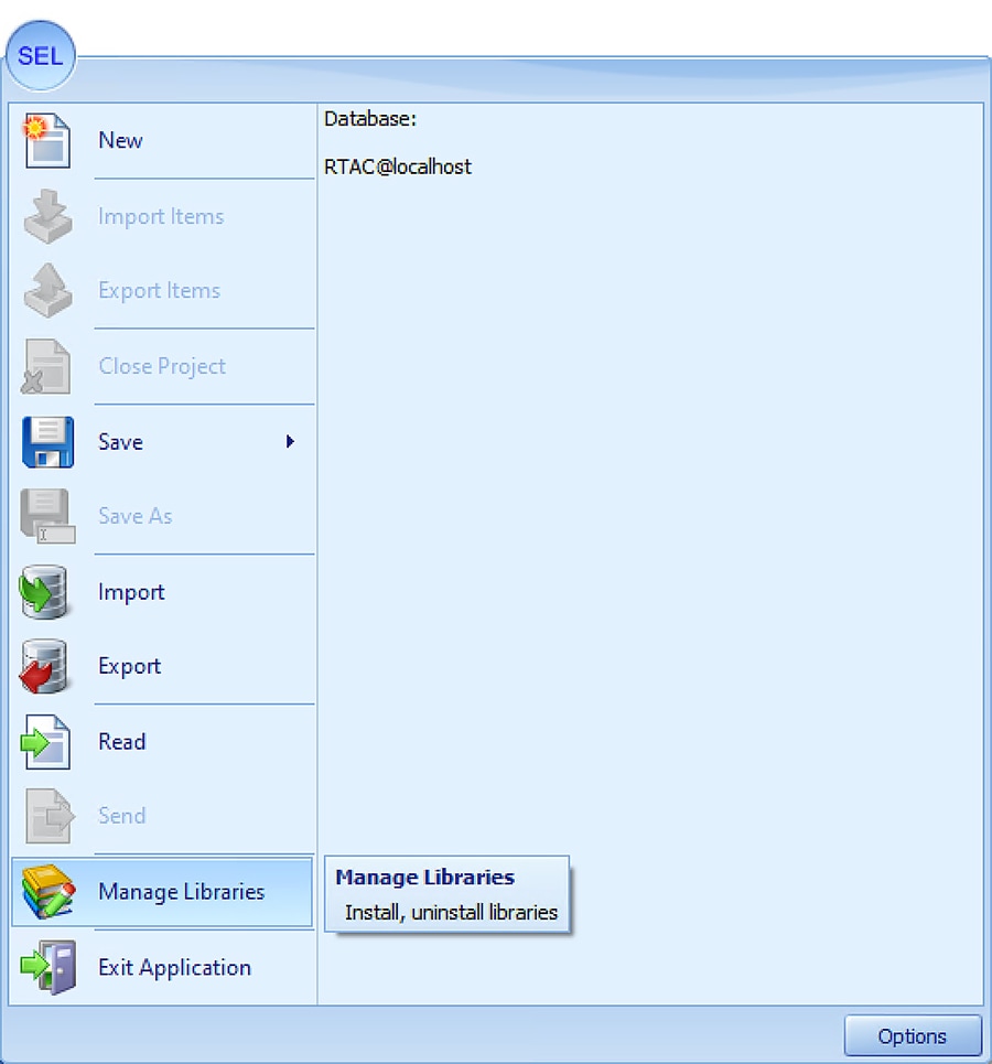
Libraries can only be imported one at time. Multiple file import is not supported. User need to wait for the first file import to complete, before importing the second file.
Figure 157 DAC Library installation
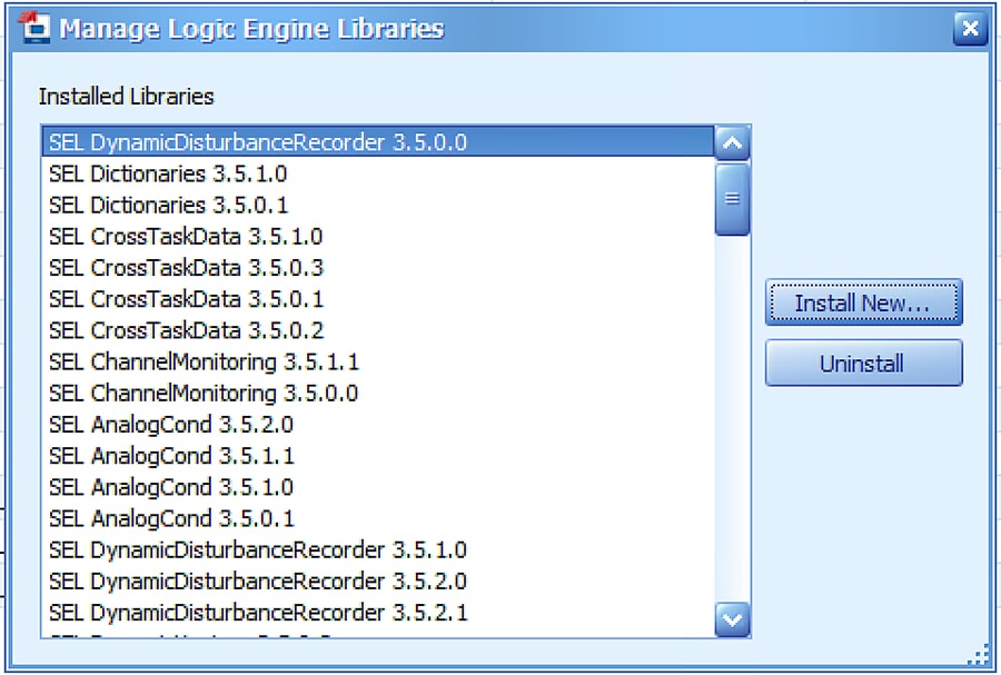
Note: Initially, there are not any SEL DAC library selections in the window. The user must click Install New to install new DAC libraries into the SEL application and make them available in the Manage Library window.
6.![]() Choose library files to Import.
Choose library files to Import.
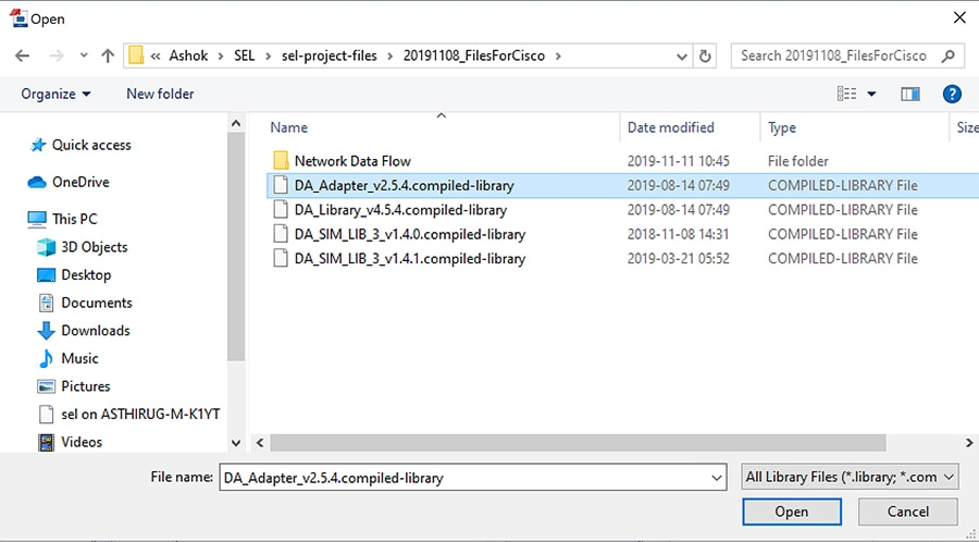
The four library files in the table below must be selected and installed one at a time.
Table 26 SEL DAC Library details
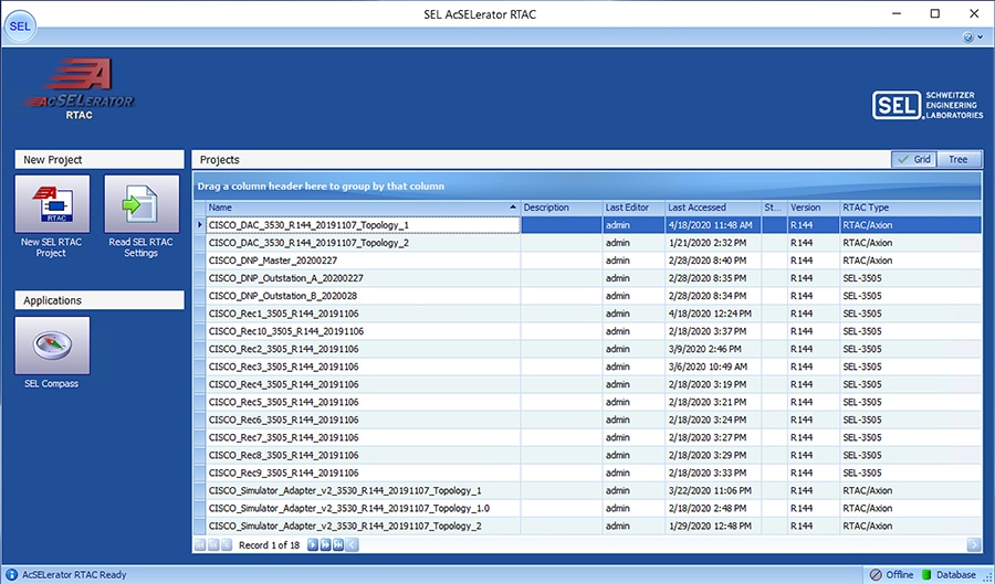
When the user opens the SEL AcSELerator application after importing the projects and libraries files, the user is presented with list of available projects to load, as shown above.
Select the required project to load on the application workspace.
SEL 3530 DAC configuration
One of the SEL RTACs 3530 is used as a DAC Controller and the other one used as a FLISR simulator, which simulates the SCADA Server, Breaker switches and also FLISR use case events to all SEL-RTAC devices.
The following section describes on how to configure DAC and Recloser for DNP3 communication protocol.
1.![]() Navigate to the DAC project folder structure shown below.
Navigate to the DAC project folder structure shown below.
Figure 160 SEL3530 RTAC project folder structure
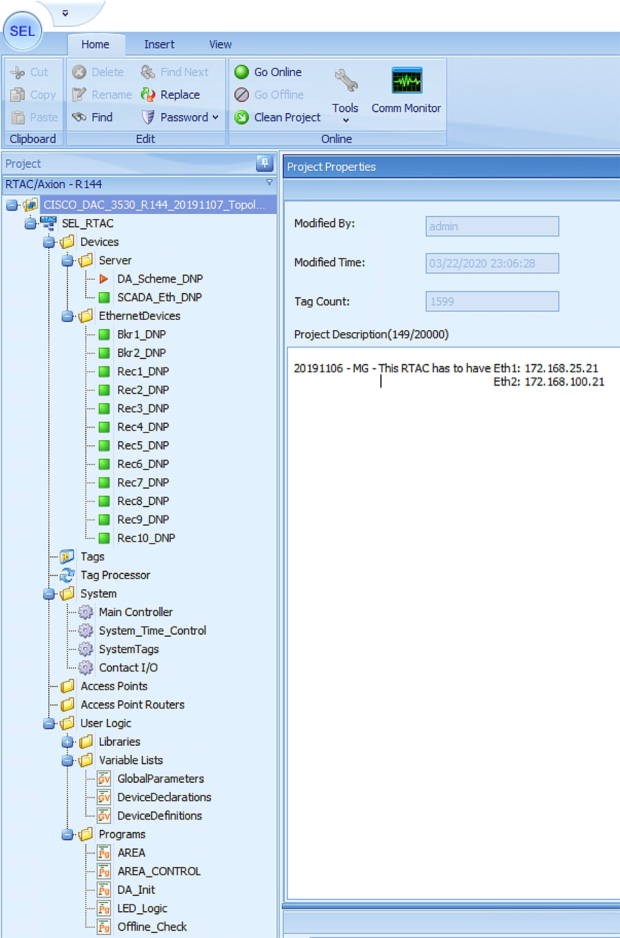
When the user loads the project, the left panel displays the complete folder structure of the projects loaded. The two major configurations which requires modification with respect to the deployment or test bed configuration are Server (explained in Step2) and IED configurations details (explained in Step3).
2.![]() Click on the SCADA_Eth_DNP under Server menu item on left panel.
Click on the SCADA_Eth_DNP under Server menu item on left panel.
Figure 161 SEL3530 RTAC SCADA DNP configuration
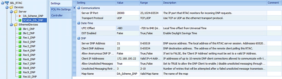
When the user loads the project, the left panel display the complete folder structure of the projects loaded. The two major configurations which requires modification with respect to the deployment or test bed configuration are Server and IED configurations details.
Update the configuration as shown in the table below.
Table 27 SEL RTAC 3530 DNP Server configuration
|
|
|
|
|
|
|
|
|
|
|
|
|
|
|
|
|
|
|
|
|
|
|
|
|
|
|
|
|
|
|
|
3.![]() Click Rec1_DNP under EthernetDevices menu item.
Click Rec1_DNP under EthernetDevices menu item.
Under the Ethernet Devices, DNP3 configuration for Reclosers and Breakers are listed in Figure 27.
Figure 162 SEL3530 RTAC Recloser configuration
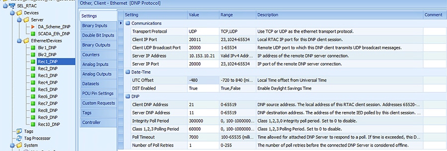
Update the configuration as shown in the table below.
Update all ten Reclosers with the configuration details shown below. The two Breaker switches typically do not require an update.
Table 28 SEL RTAC 3530 Recloser configuration
SEL 3505 Recloser configuration
There are ten SEL RTAC 3505 in this FLISR test setup. Each of these ten devices emulates Recloser and Recloser controller functionalities.
All ten Recloser project configurations need to be updated for the deployment or testbed setup.
The following section describes on how to configure the Reclosers for DNP3 communication protocol.
1.![]() Recloser Project Folder Structure
Recloser Project Folder Structure
Figure 163 SEL3505 Recloser folder structure
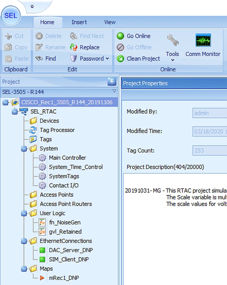
When the user loads the project, the left panel display the complete folder structure of the projects loaded. The two major configurations which requires modification with respect to the deployment or test bed configuration are DAC Server (explained in Step 2) and SIM Client configurations (explained in Step 3) details.
2.![]() Click on DAC_Server_DNP under EthernetConnections menu item on left panel.
Click on DAC_Server_DNP under EthernetConnections menu item on left panel.
Figure 164 SEL3505 DAC Server configurations
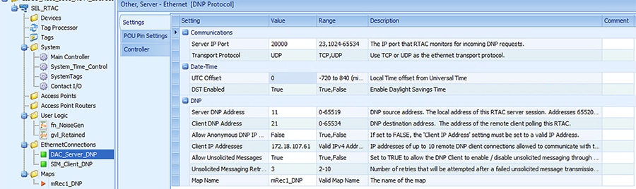
Update the configuration as shown in the table below.
Table 29 SEL RTAC 3530 DNP Server configuration
|
|
|
|
|
|
|
|
|
|
|
|
|
|
|
|
|
|
|
|
|
|
|
|
|
|
|
|
|
|
|
|
3.![]() Click on SIM_Client_DNP under EthernetConnections
Click on SIM_Client_DNP under EthernetConnections
Figure 165 SEL3505 Client Configuration
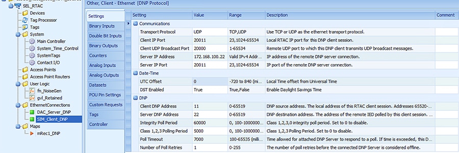
Update the configuration as shown in the table below.
Table 30 SEL RTAC 3530 Recloser configuration
Pushing Configuration Changes to the devices
The SEL FLISR project needs to be pushed into each SEL device for the simulation to work. The following steps describes on how to push the configuration or update the configuration of SEL devices. The steps are common for all types of SEL devices, whether it is SEL RTAC 3530 or 3505.
There are four stage process for pushing the configuration to the devices,
Load the Project Click Go Online Enter CredentialsConfirm Go Online
1.![]() Load the FLISR Simulation project file. Select the project to load by double clicking on the project file name.
Load the FLISR Simulation project file. Select the project to load by double clicking on the project file name.
Figure 166 Load project into application workspace
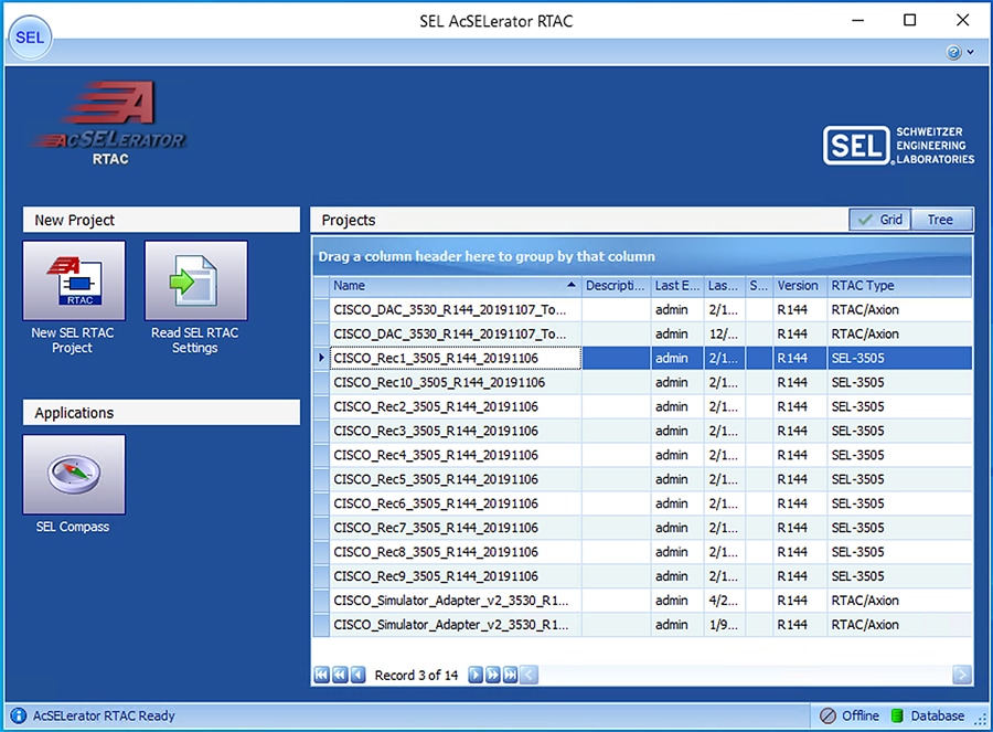
2.![]() Click Go Online. Go online with SEL RTAC devices by clicking Go Online. This action will push the configuration or update configuration on SEL RTAC device with the latest configuration in the SEL application workspace.
Click Go Online. Go online with SEL RTAC devices by clicking Go Online. This action will push the configuration or update configuration on SEL RTAC device with the latest configuration in the SEL application workspace.
Figure 167 Push configuration to SEL device by Going Online
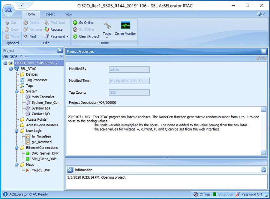
3.![]() Input SEL RTAC credentials and then click Login. Provide the SEL RTAC credentials to enable the application to access and updated the configuration on the device.
Input SEL RTAC credentials and then click Login. Provide the SEL RTAC credentials to enable the application to access and updated the configuration on the device.
Figure 168 SEL RTAC credentials window
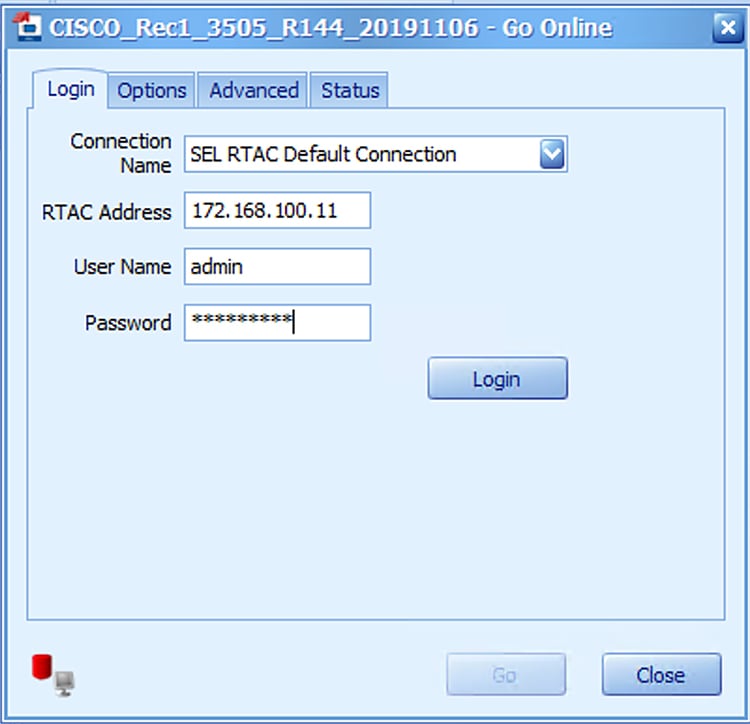
4.![]() Click Go. Details of connection status to the SEL device and the details of the project being pushed into the SEL display in this window.
Click Go. Details of connection status to the SEL device and the details of the project being pushed into the SEL display in this window.
Figure 169 Go Online confirmation window
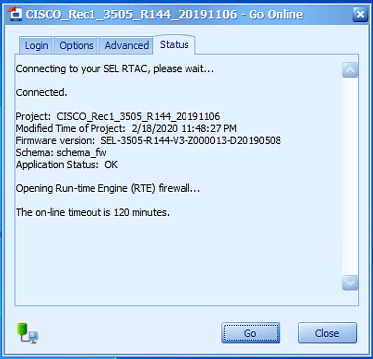
5.![]() Confirm the SEL device is online. Confirm the SEL RTAC device online status, by verifying the logs message has 0 errors and the status is Online with green dot on status bar.
Confirm the SEL device is online. Confirm the SEL RTAC device online status, by verifying the logs message has 0 errors and the status is Online with green dot on status bar.
Figure 170 SEL Device Online status
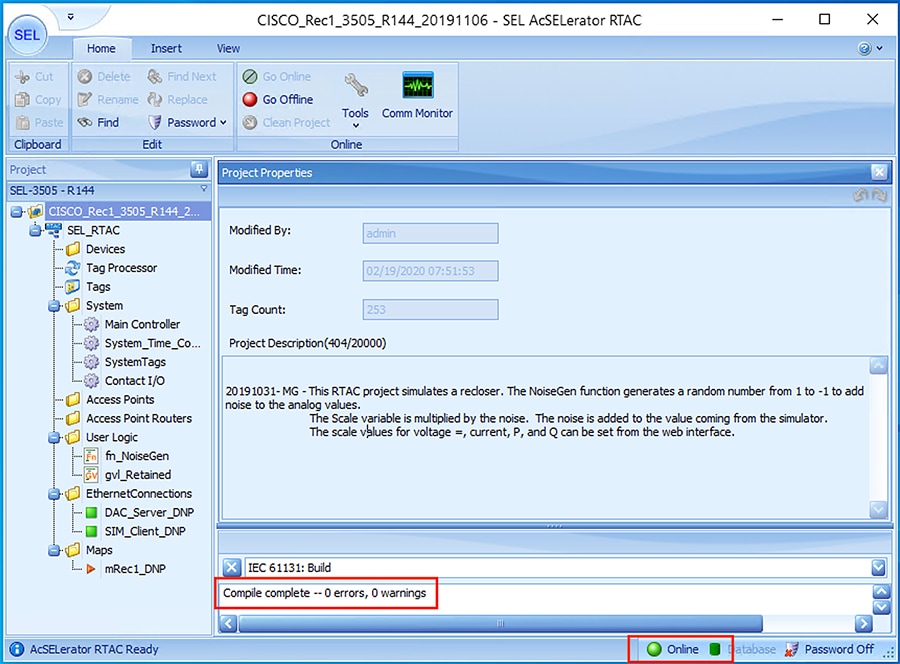
Simulation Go-Online for FLISR simulation
6.![]() Load the FLISR Simulation project file. The FLISR simulation filename starts with CISCO_Simulator. Double click the filename.
Load the FLISR Simulation project file. The FLISR simulation filename starts with CISCO_Simulator. Double click the filename.
Figure 171 Load FLISR simulation file
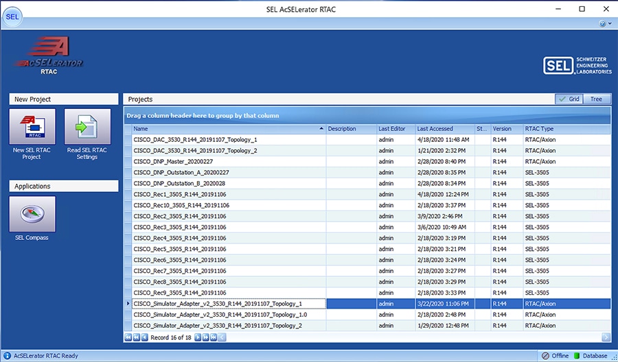
7.![]() Open Main Visualization. The Main Visualization GUI is a dashboard graphical user interface, providing a means for all FLISR user case events to be initiated, monitored, and visualized.
Open Main Visualization. The Main Visualization GUI is a dashboard graphical user interface, providing a means for all FLISR user case events to be initiated, monitored, and visualized.
Figure 172 Main Visualization menu item
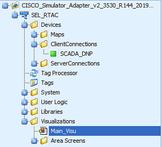
8.![]() Go Online, by clicking Go Online.
Go Online, by clicking Go Online.
The main visualization provides the electrical line diagram of the topology with the recloser, breakers and source of power. It also shows the details of status of each device, load points.
The GUI provide buttons to simulate a fault, restore, RTN events.
More details of this line diagram can be found in the DA Feeder Automation Design Guide.
Figure 173 Initial Offline state
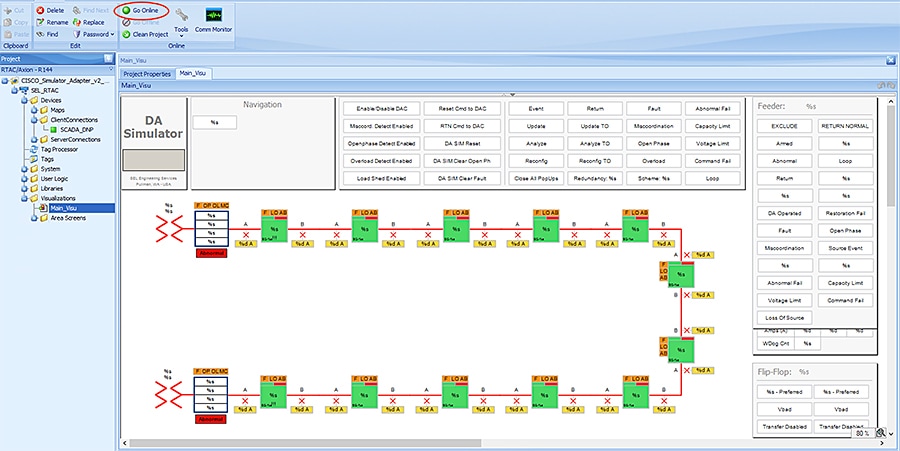
9.![]() Input SEL RTAC credentials and then click Login. Providing the SEL RTAC credentials enables the application to access and update the configuration on the device.
Input SEL RTAC credentials and then click Login. Providing the SEL RTAC credentials enables the application to access and update the configuration on the device.
Figure 174 FLISR Simulator credentials window
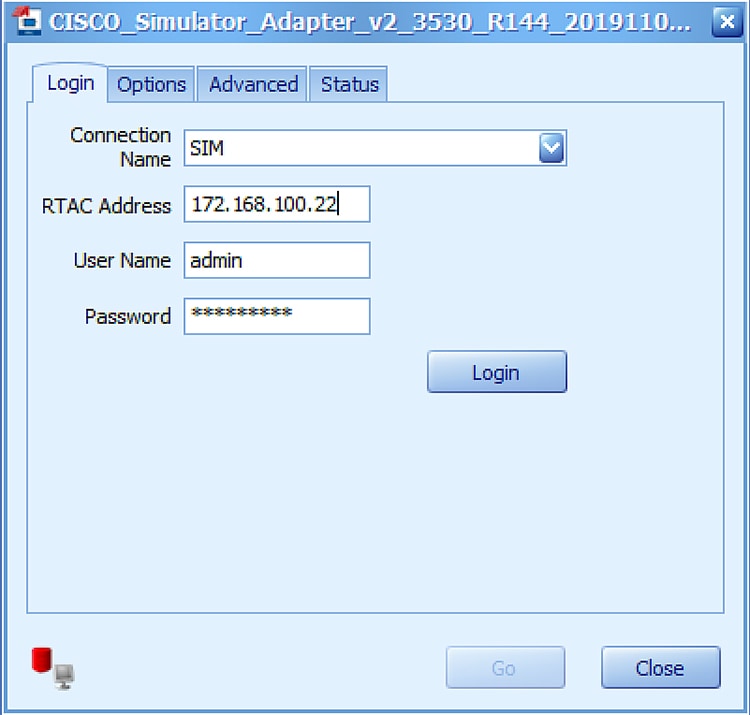
10.![]() Click Go. Details of connection status to the SEL device and the details of the project being pushed into the SEL display in this window.
Click Go. Details of connection status to the SEL device and the details of the project being pushed into the SEL display in this window.
Figure 175 FLISR simulation Going online
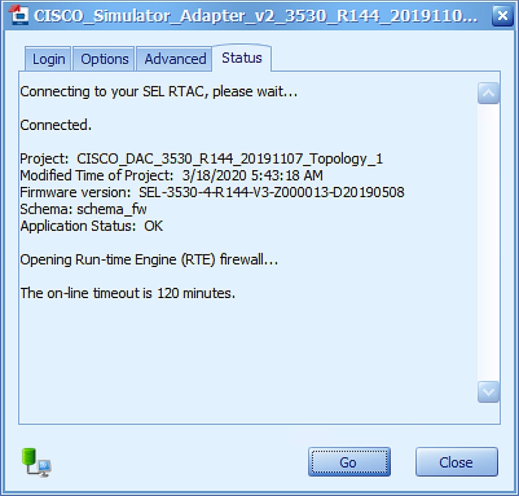
11.![]() If you need to make changes to the project, click Yes. This window appears only when there is change in the configuration between the device and current configuration being pushed into it.
If you need to make changes to the project, click Yes. This window appears only when there is change in the configuration between the device and current configuration being pushed into it.
Figure 176 FLISR send settings to simulator device
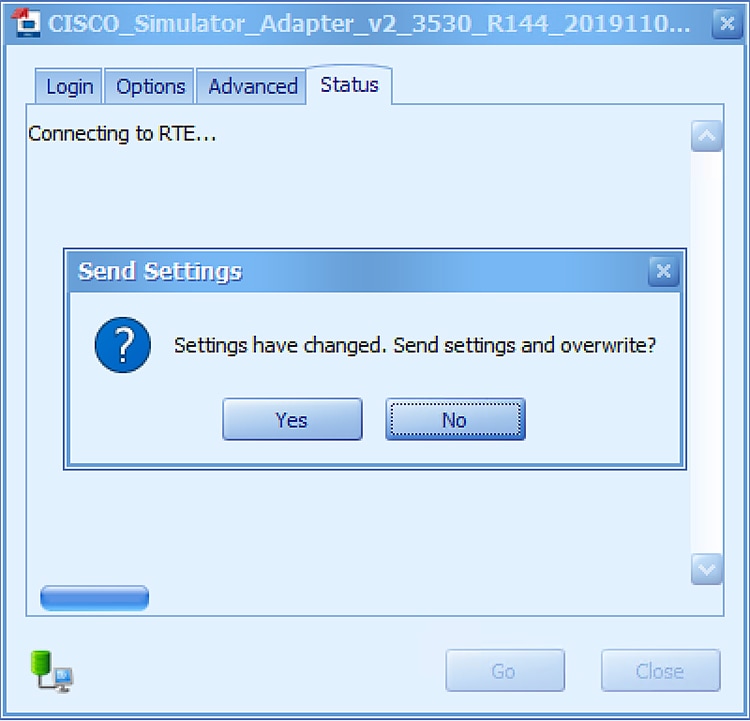
12.![]() Click Enable/Disable DAC to initiate the communications to all RTACs including the DAC and simulator.
Click Enable/Disable DAC to initiate the communications to all RTACs including the DAC and simulator.
By default, when the simulation goes online, the simulated electrical circuits remains unarmed, which means there is no flow of current in the circuit. To start the current flow and arm the circuit, the GUI provides an Enable/Disable DAC button. The status of electrical circuit can be verified by “UNARMED” in legend box and as well the Enable/Disable button color, white when it is Disabled and Green when it is Enabled.
Figure 177 FLISR simulation Disabled state
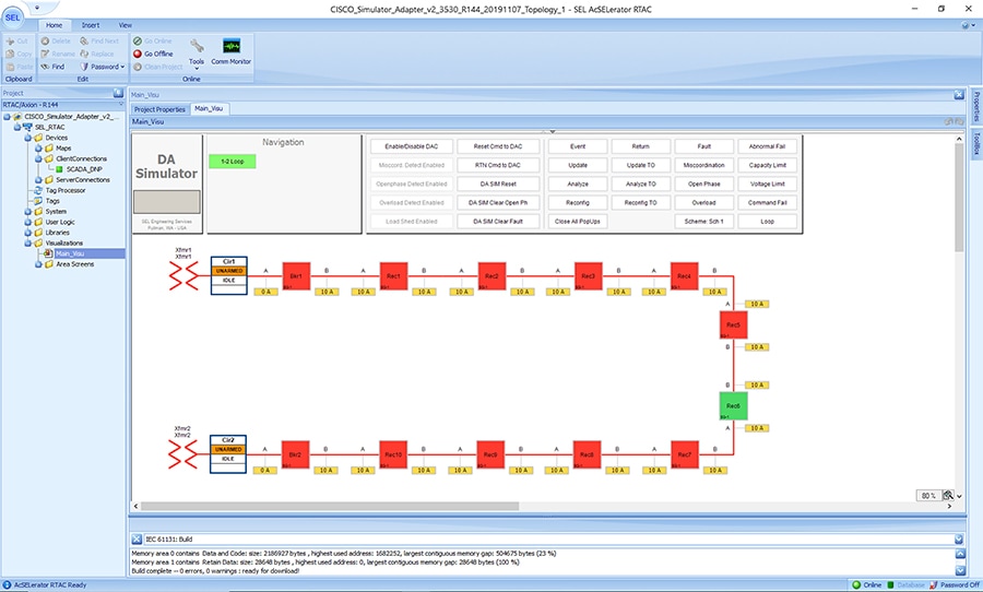
Figure 178 FLISR simulation Enabled state
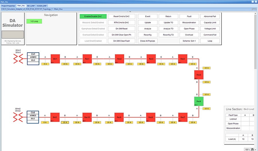
After enabling the DAC, verify that no “Abnormal” text box appears below the status box in the electrical line diagram. When “Abnormal” text appears, when there is a communication failure between one or more of the SEL RTAC devices. Fix the communication errors before proceeding to FLISR Use case simulation.
FLISR Fault Lockout simulation
Figure 179 FLISR Fault Lockout use case flow diagram
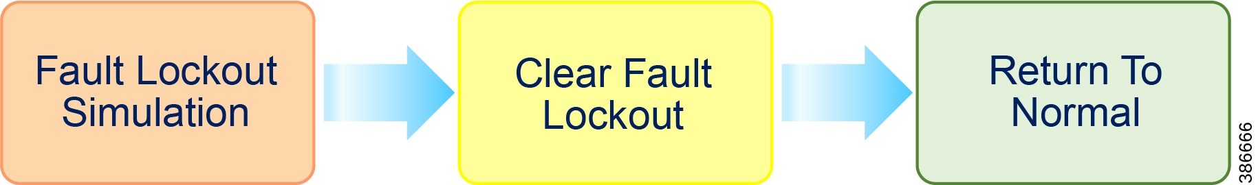
Fault Lockout Simulation, Simulate the fault between any two reclosers. Once the fault is inserted in a segment, the FLISR simulation recognizes the fault and initiates FLISR process in which, the first step is Identifying and Isolating the faulty segment by opening the Reclosers closest to the segment. And, the next step is Restoring the power to the other segments in the circuit from the other available source by closing the Normally Open Recloser6.
Clear Fault Lockout, Clear the fault created in the first step, which means in real deployment scenario the fault is fixed or resolved, but still the power is not restored to this segment.
Return to Normal, Reset the simulation to the normal state. Return to Normal process involves, resetting the circuits to its initial state before the fault occurrence. Typically, the power is restored to the faulty, which is fixed now segment by closing the Reclosers which are opened during Fault Isolation process and opening the Normally Open Recloser6.
For more details on FLISR use case, refer to Distribution Automation Feeder Automation Design Guide.
Fault Lockout simulation steps
1.![]() Click on the yellow colored load icon 10A, between the reclosers Rec2 and Rec3
Click on the yellow colored load icon 10A, between the reclosers Rec2 and Rec3
Figure 180 Fault Lockout normal state
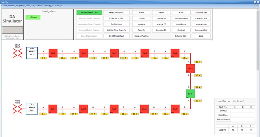
On clicking the load icon 10A, a table appears at bottom right corner of the GUI window, with the title as Line Section: Rec2-LineB. The table has fault type on first column and next three columns A, B & C represents the phases of current.
2.![]() To start simulating Fault lockout, click on the white box on second row, which has the Fault Type as Lockout.
To start simulating Fault lockout, click on the white box on second row, which has the Fault Type as Lockout.
Figure 181 Fault Lockout fault simulation
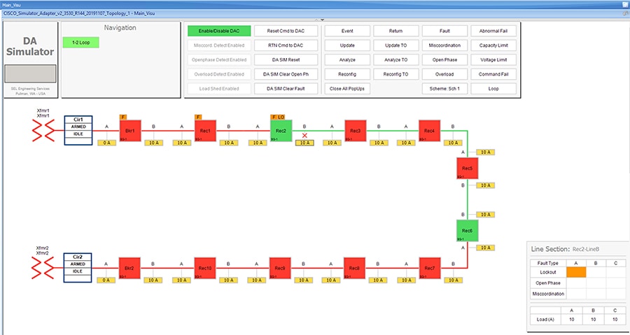
For the simulation, there is no difference between column A, B or C. So choosing any box on these columns produce the same results. The Fault Type is a more important factor parameter when deciding which FLISR use case needs to be executed in the setup.
3.![]() Wait for the simulation events to be executed by the application. When the Fault simulation is successfully completed the Fault button is highlighted in orange color and there are no errors displayed on the simulation window.
Wait for the simulation events to be executed by the application. When the Fault simulation is successfully completed the Fault button is highlighted in orange color and there are no errors displayed on the simulation window.
Figure 182 Fault lockout FLISR state
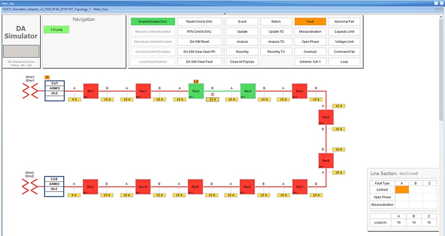
Verify the simulation has created a Fault in between reclosers Rec2 and Rec3, then the Fault is identified by the simulation, based on the fault the circuit is reconfigured to isolate the faulty section and power is restored to the other section of the circuit from the available power source.
In this example, the fault is created in between reclosers Rec2 and Rec3, this fault is Identified by the DAC controller and this section is Isolated by opening reclosers Rec2 and Rec3. Finally, the power is restored from Source2 by closing the Normally open recloser Rec6.
For more details on FLISR events, please refer to the FLISR Event Sequence Diagram section.
4.![]() Click on the DA SIM Clear Fault button on the top panel.
Click on the DA SIM Clear Fault button on the top panel.
Figure 183 Clear Fault Lockout
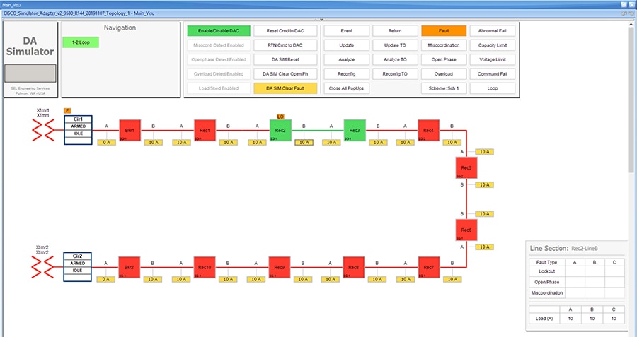
Verify that fault icon, the red x on load line between Rec2 and Rec3 disappears and also the orange color disappears on row two against the Lockout fault type, which is displayed on the Line Section box at the bottom right corner of the GUI window.
5.![]() Return to Normal command, to reset the simulator and all SEL RTAC device setting to the Normal state, click on RTN Cmd to DAC.
Return to Normal command, to reset the simulator and all SEL RTAC device setting to the Normal state, click on RTN Cmd to DAC.
Figure 184 Fault Lockout Return To Normal
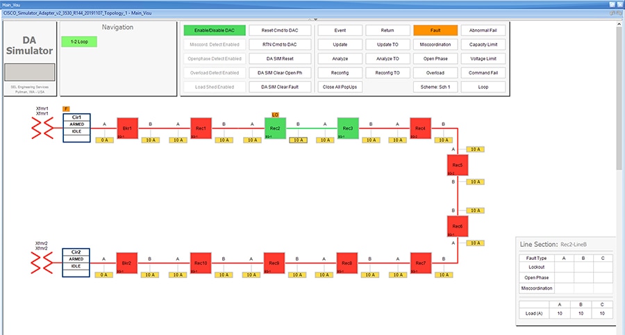
The RTN command to DAC resets the simulator and as well as all SEL RTAC device settings to normal state, which is prior to the FLISR event.
6.![]() Verify the setup has returned to Normal state.
Verify the setup has returned to Normal state.
Verify the circuit returned to Normal state by confirming that all Normally closed reclosers are Closed, in this example Rec1 to Rec2 are Closed. And, all Normally opened reclosers are Opened, in this example, the Rec6 is Open.
Also, verify that both Breakers are in Closed state and there are no errors displayed.
The total time taken for successful Fault Isolation and Restoration over CR mesh is well within the recommended industry standard. The time take by the FLISR events can be viewed from the event duration time from FLISR events logs. Refer to the section “Events HTML file”.
Figure 185 Fault Lockout back to normal state

FLISR Open Phase simulation
Figure 186 FLISR Open Phase use case flow diagram
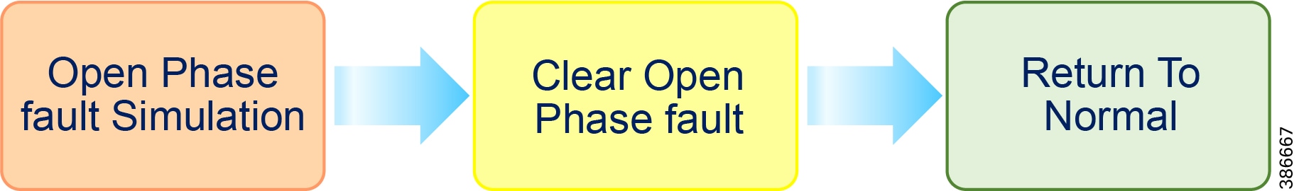
Open Phase Fault Simulation, Simulate the fault between any two reclosers. Once the fault is inserted in a segment, the FLISR simulation recognizes the Open Phase in the circuit and initiates FLISR process in which, the first step is Identifying and Isolating the faulty segment by opening the Reclosers closest to the segment. And, the next step is Restoring the power to the other segments in the circuit from the other available source by closing the Normally Open Recloser6.
Clear Open Phase Fault, Clear the open phase fault created in the first step, which means in real deployment scenario the fault is fixed or resolved, but still the power is not restored to this segment.
Return to Normal, Reset the simulation to the normal state. Return to Normal process involves, resetting the circuits to its initial state before the fault occurrence. Typically, the power is restored to the faulty, which is fixed now segment by closing the Reclosers which are opened during Fault Isolation process and opening the Normal Open Recloser6.
Open Phase Fault simulation steps
1.![]() To simulate the Open phase, click on the yellow load icon 10A, between the reclosers Rec8 and Rec9.
To simulate the Open phase, click on the yellow load icon 10A, between the reclosers Rec8 and Rec9.
Figure 187 Open Phase normal state
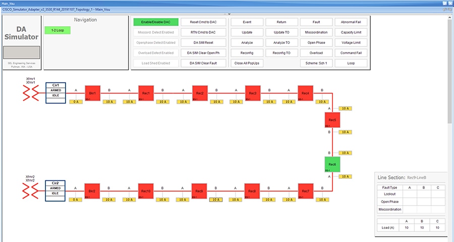
On clicking the load icon 10A, a table appears at bottom right corner of the GUI window, with the title as Line Section: Rec9-LineB. The table has fault type on first column and next three columns A, B & C represents the phases of current.
2.![]() To start simulating Open Phase fault, click on the white box on the third row, which has the Fault Type as Open Phase.
To start simulating Open Phase fault, click on the white box on the third row, which has the Fault Type as Open Phase.
Figure 188 Open Phase fault simulation

For the simulation, there is no difference between column A, B or C. So choosing any box on these columns produce the same results. Whereas, the Fault Type is more import factor parameter which decide which FLISR use case needs to be executed in the setup.
3.![]() Wait for the simulation events to be executed by the application. When the Fault simulation is successfully completed the Open Phase button is highlighted in orange color and there are no errors displayed on the simulation window.
Wait for the simulation events to be executed by the application. When the Fault simulation is successfully completed the Open Phase button is highlighted in orange color and there are no errors displayed on the simulation window.
Figure 189 Open Phase FLISR state
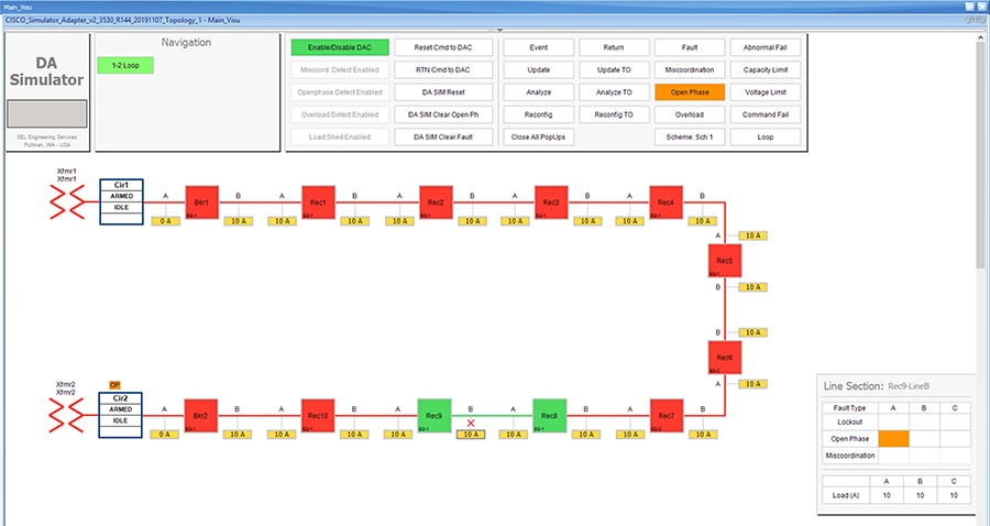
Verify the simulation has created an Open Phase fault in between reclosers Rec8 and Rec9, then the Fault is identified by the simulation, based on the fault the circuit is reconfigured to isolate the faulty section and power is restored to the other section of the circuit from the available power source.
In this example, the Open Phase fault is created in between reclosers Rec8 and Rec9, this fault is Identified by the DAC controller and this section is Isolated by opening reclosers Rec8 and Rec9. Finally, the power is restored from Source1 by closing the Normally open recloser Rec6.
For more details on FLISR events, please refer to the FLISR Event Sequence Diagram section.
4.![]() Click on the DA SIM Clear Open Ph button on the top panel, to clear the Open Phase fault on the circuit
Click on the DA SIM Clear Open Ph button on the top panel, to clear the Open Phase fault on the circuit
Figure 190 Open Phase clear fault

Verify that fault icon, the red x on load line between Rec8 and Rec9 disappears and also the orange color disappears on row three against the Open Phase fault type, which is displayed on the Line Section box at the bottom right corner of the GUI window.
5.![]() Return to Normal command, to reset the simulator and all SEL RTAC device setting to the Normal state, click on RTN Cmd to DAC button.
Return to Normal command, to reset the simulator and all SEL RTAC device setting to the Normal state, click on RTN Cmd to DAC button.
Figure 191 Open Phase Return To Normal
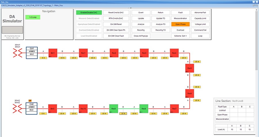
The RTN command to DAC resets the simulator and as well as all SEL RTAC device settings to normal state, which is prior to the FLISR event.
6.![]() Verify the setup has returned to normal state.
Verify the setup has returned to normal state.
Figure 192 Open Phase back to Normal state

Verify the circuit returned to Normal state by confirming that all Normally closed reclosers are Closed, in this example Rec8 to Rec9 are Closed. And, all Normally opened reclosers are Opened, in this example, the Rec6 is Open.
Also, verify that both Breakers are in Closed state and there are no errors displayed.
The total time taken for successful Fault Isolation and Restoration over CR mesh is well within the recommended industry standard. The time take by the FLISR events can be viewed from the event duration time from FLISR events logs. Refer section “Events HTML file”.
FLISR Loss of Source simulation
Figure 193 FLISR Loss of Source use case flow diagram

Loss of Source Fault Simulation, Simulate the Loss of Source, by simulating the Voltage Loss on one of the sources. Once the loss of voltage is inserted in a circuit, the DAC recognizes the voltage loss in the circuit and initiates FLISR process in which, the first step is to Identify and Isolate the Source by opening the Breakers closest to the Source, which lost the voltage. And, the next step is Restoring the power to other segments in the circuit from the available source by closing the Normally Open Recloser6.
Restore Voltage on Source, Clears the fault created in the first step, which means in real deployment scenario the fault is fixed or resolved, but still the power is not flowing to the circuit from the source.
Return to Normal, Reset the simulation to the normal state. Return to Normal process involves, resetting the circuits to its initial state before the fault occurrence. Typically, the voltage is restored from the faulty source, which is fixed now. Power is restored in the circuits by closing the Breakers, which are closed during Fault Isolation process and opening the Normally Open Recloser6.
Loss of Source Fault simulation steps
1.![]() Simulate Loss of Source on circuit 1 by clicking the source transformer xfmr1 icon.
Simulate Loss of Source on circuit 1 by clicking the source transformer xfmr1 icon.
Figure 194 Loss of Source Normal state
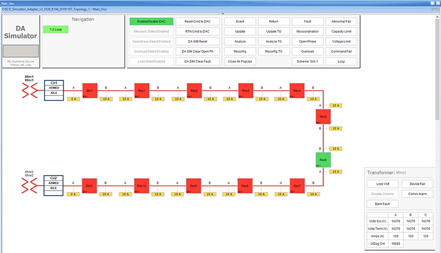
On clicking the transformer icon xmfmr1, a table appears at bottom right corner of the GUI window, with the title Transformer: Xfmr1. The table displays the status of the voltage on the circuit. One type of loss of source is due to fault in the transformer which fails to serve required voltage to the circuit resulting in a loss of source.
2.![]() Click on the Loss Volt button on table Transformer: Xfmr1, to simulate the Loss of Source.
Click on the Loss Volt button on table Transformer: Xfmr1, to simulate the Loss of Source.
Figure 195 Loss of Source lost voltage
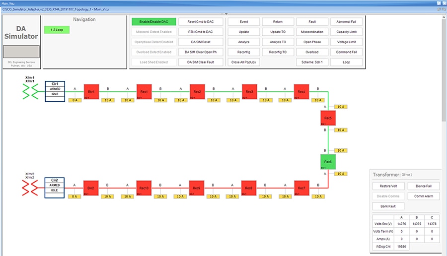
Verify the simulation has created a Loss of Source in transformer Xfmr1, by confirming the change of color of Xfrm1 icon from Red to Green. The electrical line also changes color from Red to Green representing there is no Voltage on the circuit.
For more details on FLISR events, refer to the FLISR Event Sequence Diagram section.
3.![]() Wait for the simulation events to be executed by the application. When the Loss of Source simulation is successfully completed, the Restore volt button appears and no error message is displayed on the simulation window.
Wait for the simulation events to be executed by the application. When the Loss of Source simulation is successfully completed, the Restore volt button appears and no error message is displayed on the simulation window.
Figure 196 Loss of Source FLISR state
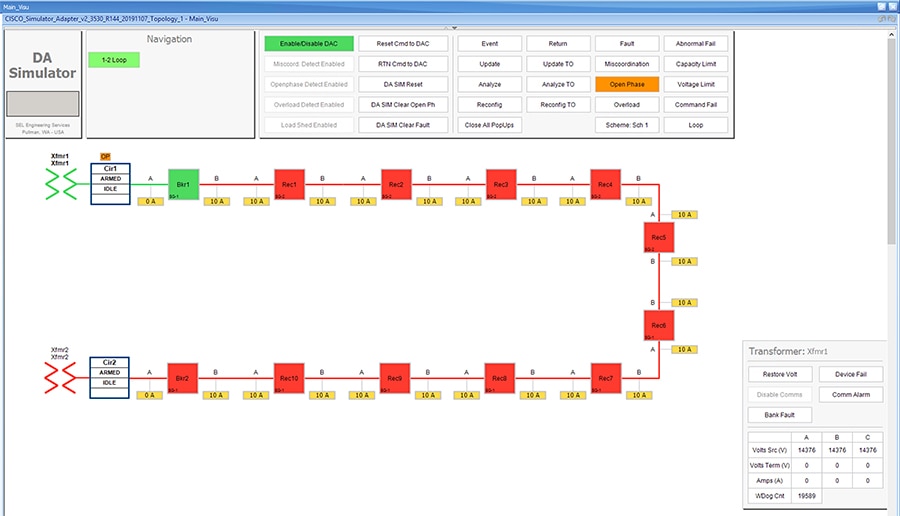
Verify the Loss of Source simulation successfully completed by confirming that Source Transformer Xfmr1 is isolated by opening the Breaker1 switch. Power is restored to circuit1 from the other source Transformer Xfmr2, by closing the Normally open Recloser Rec6.
4.![]() Click the Restore Volt button in the Transformer: Xfmr1 table, as shown in previous Figure 55.
Click the Restore Volt button in the Transformer: Xfmr1 table, as shown in previous Figure 55.
Figure 197 Loss of Source Restore voltage state
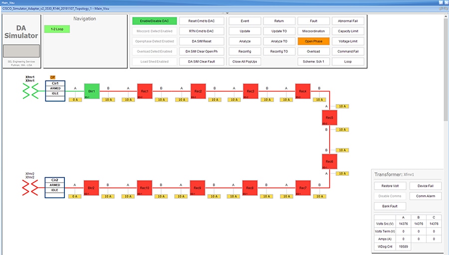
Verify the voltage is restored in source Transformer: Xfmr1, by the icon color change from green to red and Restore Volt toggles to Loss Volt.
5.![]() Return to Normal command, to reset the simulator and all SEL RTAC device setting to the Normal state, click on RTN Cmd to DAC button.
Return to Normal command, to reset the simulator and all SEL RTAC device setting to the Normal state, click on RTN Cmd to DAC button.
Figure 198 Loss of Source Return To Normal
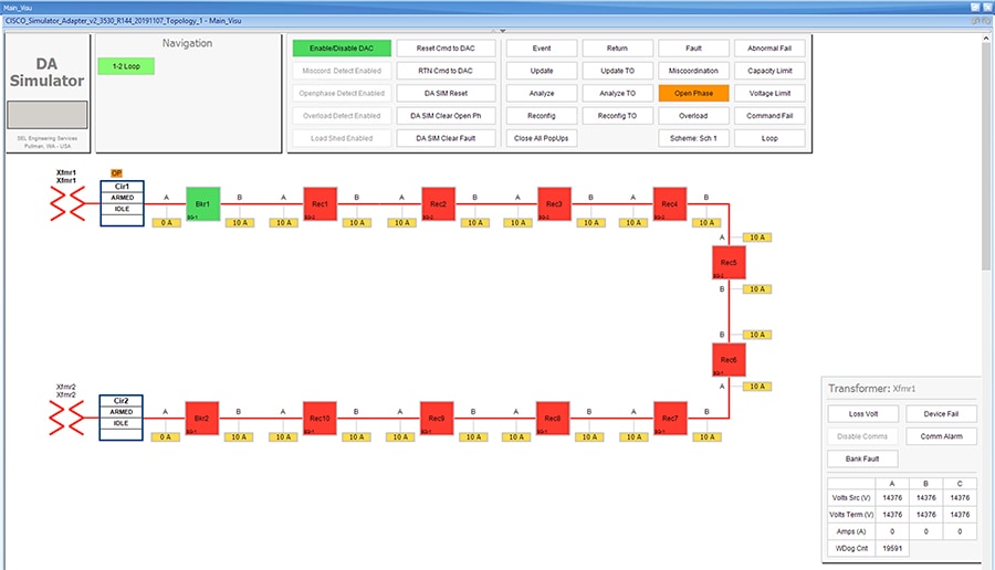
Verify the circuit returned to Normal state by confirming that all Breakers those are Normally closed are Closed, in this example Breaker1 is Closed. And, all Normally opened reclosers are Opened, in this example, the Rec6 is Open.
Also, verify that both the source Transformers are Red, which represents the Voltage flowing to the circuit from these transformers and confirm there are no errors displayed.
The total time taken for successful Fault Isolation and Restoration over CR mesh is well within the recommended industry standard. The time take by the FLISR events can be viewed from the event duration time from FLISR events logs. Refer to the section “Events HTML file”.
FLISR Event Logs
Sequence of Events
1.![]() Open https://172.29.131.1/home.sel
Open https://172.29.131.1/home.sel
using any web browser and the console cable is connected between the windows PC and the SEL device.
Click on the SOE menu item under the Reports tab on left panel.
Figure 199 FLISR Sequence of events
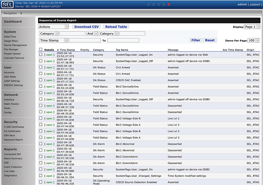
The above Sequence of Events table captures each and every event that occurred during the FLISR user case event. This table can be downloaded to local system as csv file, if further analysis is required on sequence of events or for debugging purpose.
FLISR Fault Report
Events HTML file
1.![]() Open the link https://172.29.131.1/home.sel using any web browser and the console cable is connected between the windows PC and the SEL device.
Open the link https://172.29.131.1/home.sel using any web browser and the console cable is connected between the windows PC and the SEL device.
2.![]() Click on the File Manager menu item under the System tab on left pane.
Click on the File Manager menu item under the System tab on left pane.
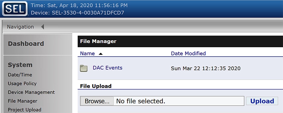
All FLISR events and their details are captured and stored in html file format. These html files are consolidated under the folder named DAC Events.
To view all DAC event files, click on the DAC Events folder link.
3.![]() Click on the DAC Events link.
Click on the DAC Events link.
Figure 201 DAC Events HTML files
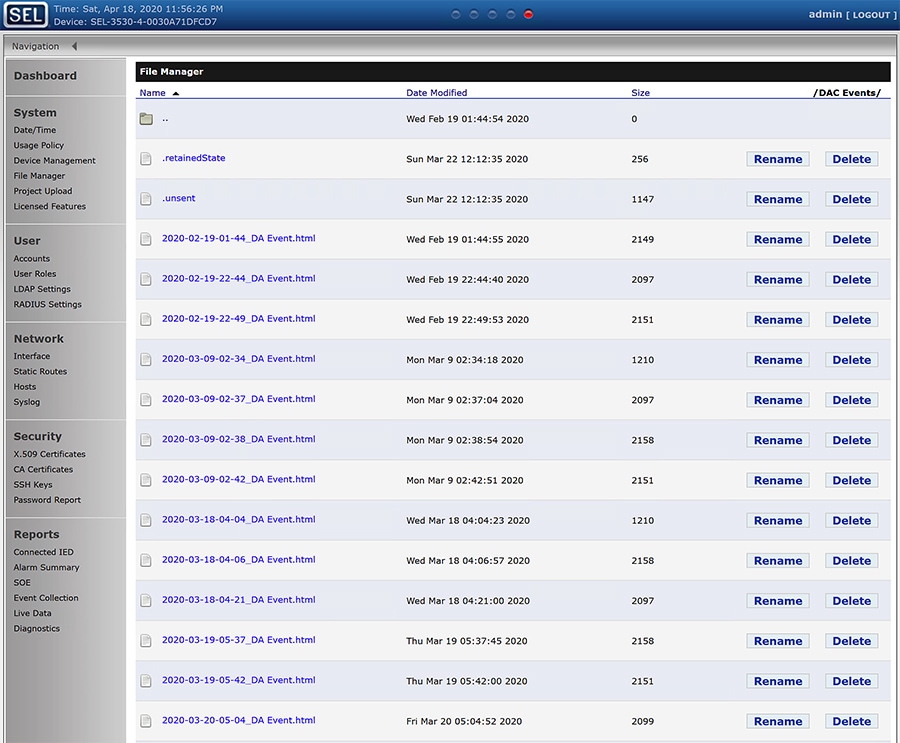
Each FLISR events are captured in an individual html file with time stamp appended to its file name.
4.![]() Click to download the FLISR events HTML file to the local machine.
Click to download the FLISR events HTML file to the local machine.
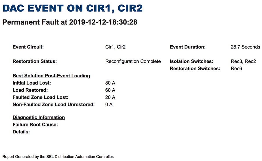
The file provides details of the FLISR events, especially time taken for the event and load details.
Edge Compute
The sample IOx Edge Compute application running on Mesh Gateway IR510 devices executes the following functions:
■![]() Sends an Unsolicited report from IED to Control Center through UDP.
Sends an Unsolicited report from IED to Control Center through UDP.
■![]() Receives request for an Integrity poll from Control Center and forwards the request to IED controller through serial communication. Also, reads the response for integrity polling and forwards the response to Control Center through UDP.
Receives request for an Integrity poll from Control Center and forwards the request to IED controller through serial communication. Also, reads the response for integrity polling and forwards the response to Control Center through UDP.
■![]() Receives a Control Command from the Control Center and forwards the command to IED controller through serial communication. Reads the response for the command and forwards the response to the Control Center through UDP.
Receives a Control Command from the Control Center and forwards the command to IED controller through serial communication. Reads the response for the command and forwards the response to the Control Center through UDP.
Figure 203 Edge Compute Schematic Drawing
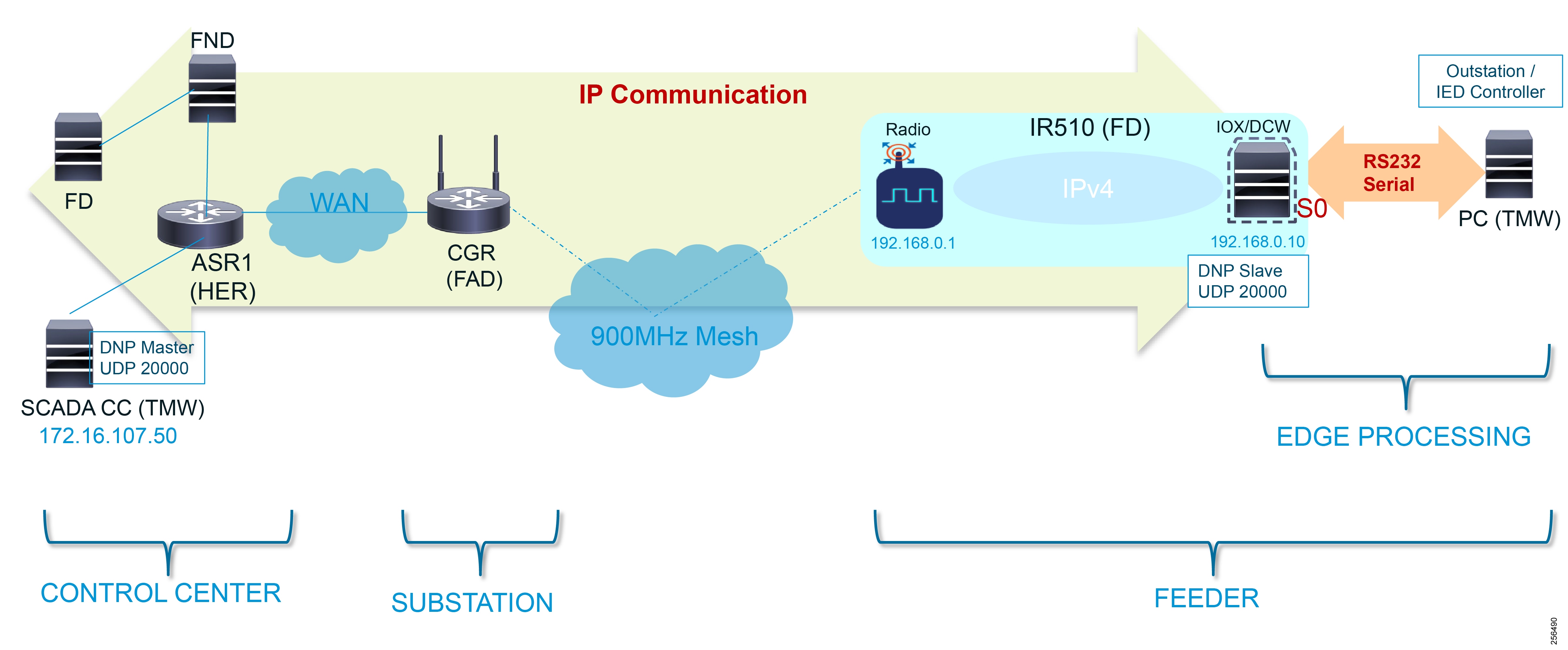
For more details on infrastructure and setup, please refer to Solution Network Topology and Addressing.
Refer to Appendix E: HER and CGR Configurations for details on how to get this pre-compiled sample Edge Compute application.
For details on IOx, IOx application development, and all information-related IOx and Edge Compute, refer to the following URL:
■![]() https://community.cisco.com/t5/cisco-iox-documents/getting-started-with-cisco-iox/ta-p/3619379
https://community.cisco.com/t5/cisco-iox-documents/getting-started-with-cisco-iox/ta-p/3619379
Application Life Cycle Management
Cisco Fog Director
Installing Cisco Fog Director
To install the Cisco Fog Director, refer to the Cisco Fog Director Reference Guide, Release 1.5 at the following URL:
■![]() https://www.cisco.com/c/en/us/td/docs/routers/access/800/software/guides/iox/fog-director/reference-guide/1-5/fog_director_ref_guide.html
https://www.cisco.com/c/en/us/td/docs/routers/access/800/software/guides/iox/fog-director/reference-guide/1-5/fog_director_ref_guide.html
Integration Steps on FND
Adding Mesh Gateway into Fog Director
Mesh Gateway is automatically imported into Fog Director (FD) from the FND. To enable this, complete the following configuration:
1.![]() Open FND and create a new user.
Open FND and create a new user.
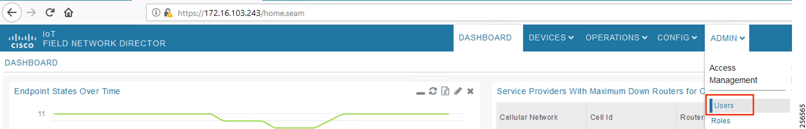
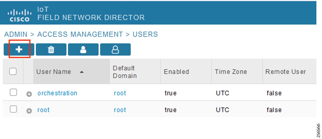
3.![]() Provide FD user details, user name as FD, password, and Time Zone as UTC.
Provide FD user details, user name as FD, password, and Time Zone as UTC.
Figure 206 Provide FD User Details
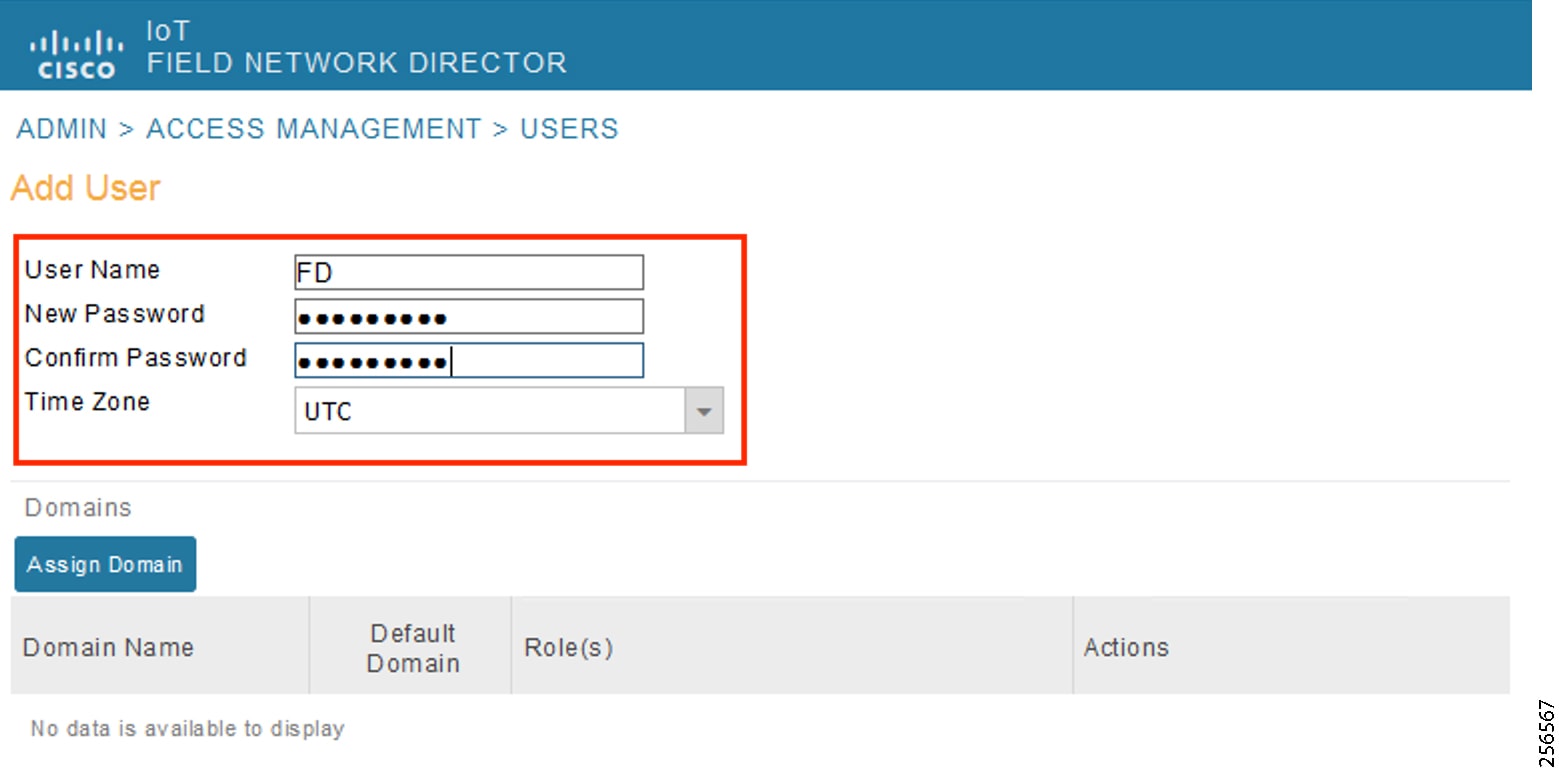
4.![]() Assign FD user role as NorthBound API.
Assign FD user role as NorthBound API.
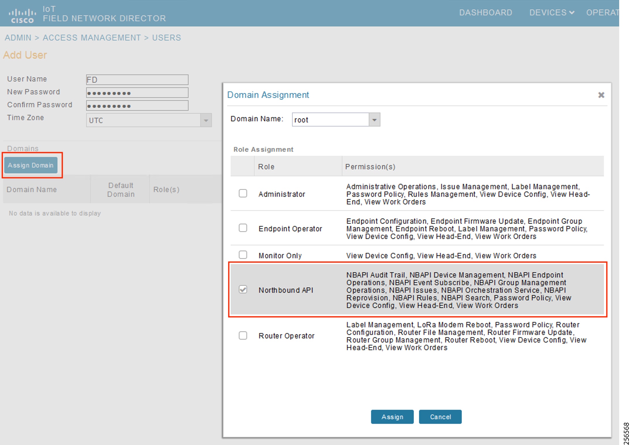
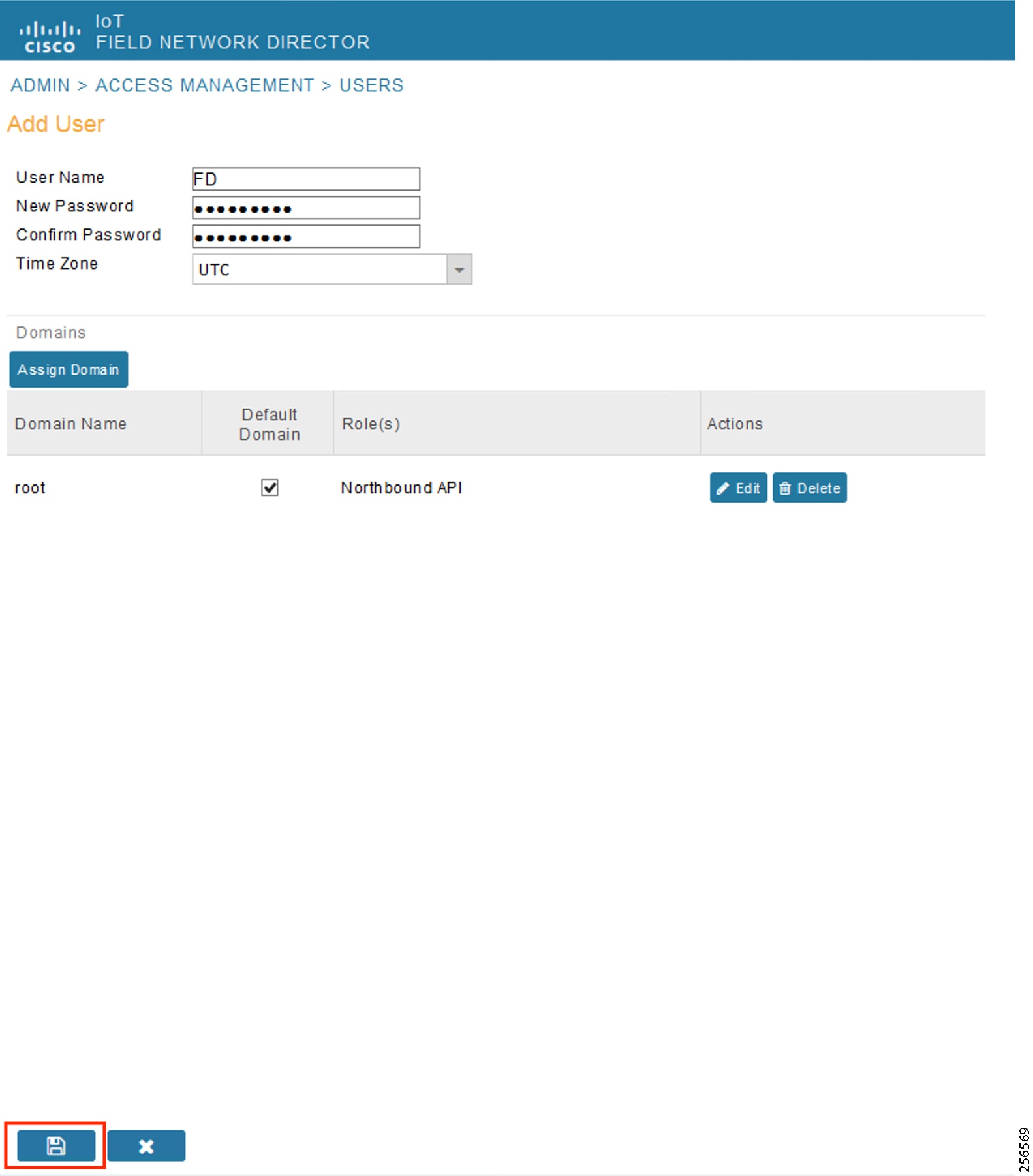
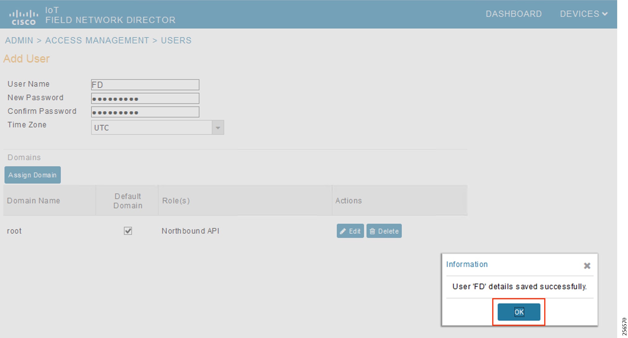
Enable Serial Communication on Endpoints
1.![]() Enable serial service in endpoints.
Enable serial service in endpoints.
Figure 210 Enable Serial Service from FND
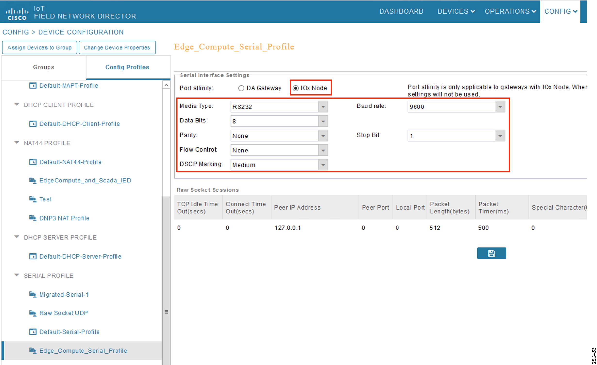
2.![]() Select IOx Node and verify that the serial settings are added as in Figure 210.
Select IOx Node and verify that the serial settings are added as in Figure 210.
Integration Steps on Fog Director
1.![]() Open FD, go to Settings > Extensions and click on the Configure link.
Open FD, go to Settings > Extensions and click on the Configure link.
Figure 211 Configure FND Extension
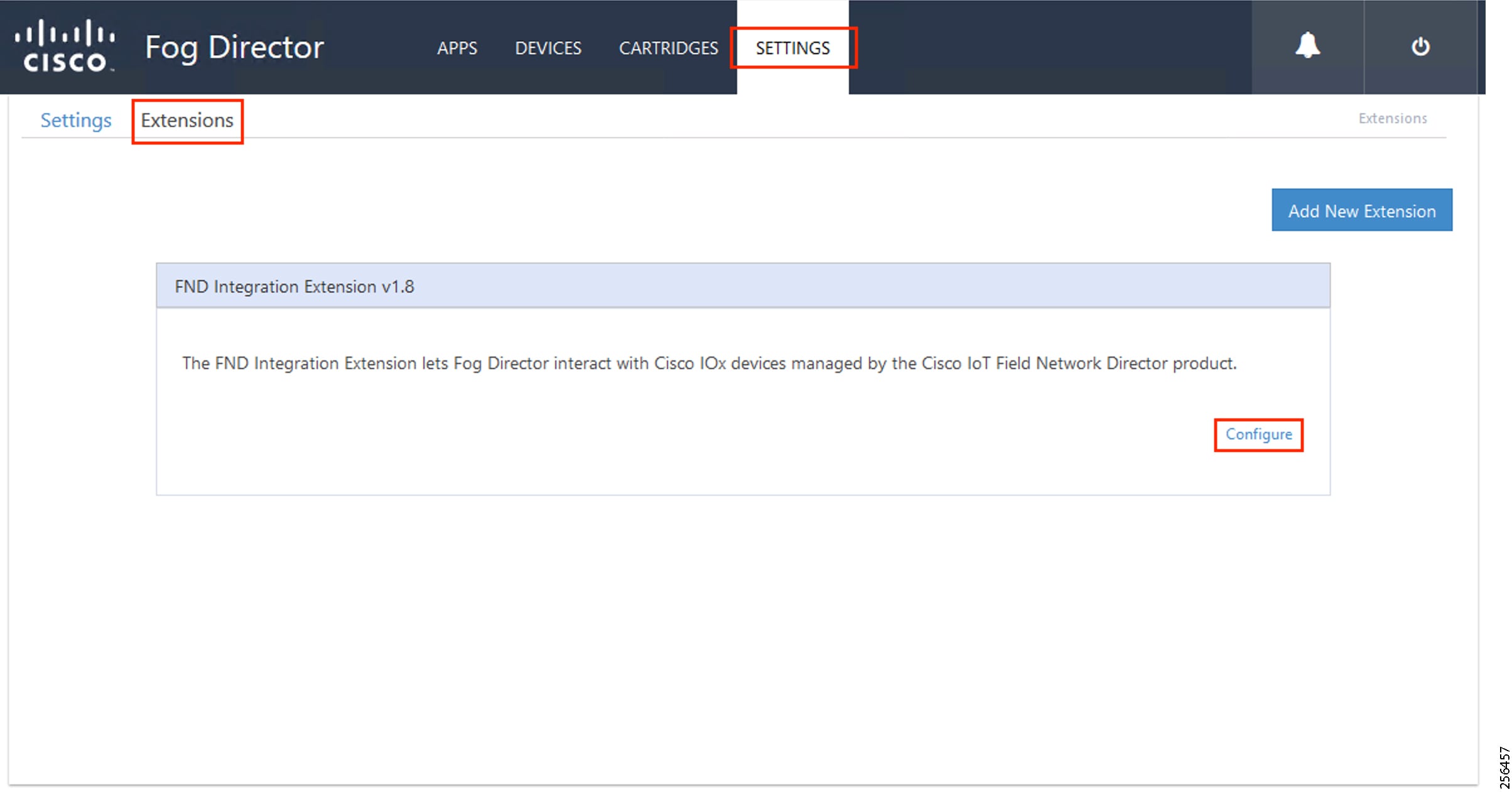
2.![]() Provide the required details in FND Integration Extension and then click Update Configuration.
Provide the required details in FND Integration Extension and then click Update Configuration.
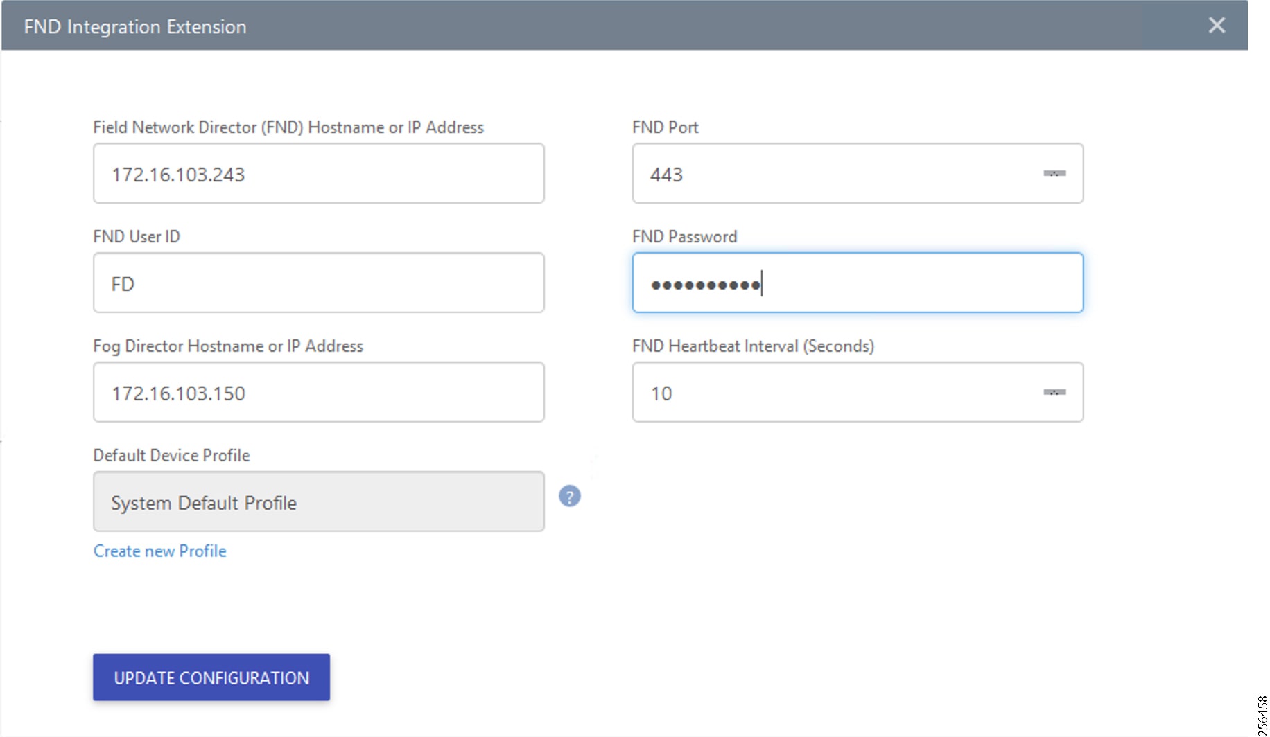
3.![]() Provide the FND IP, FNP port, FND User name, FND Password, and FD IP.
Provide the FND IP, FNP port, FND User name, FND Password, and FD IP.
4.![]() Go to Devices, click on more (…) link and select Profile menu item.
Go to Devices, click on more (…) link and select Profile menu item.
Figure 213 Choose Device Profiles
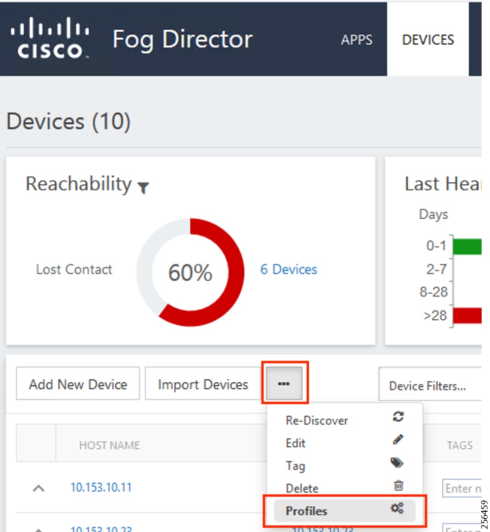
5.![]() Choose the profile to edit.
Choose the profile to edit.
Figure 214 Edit Device Profiles
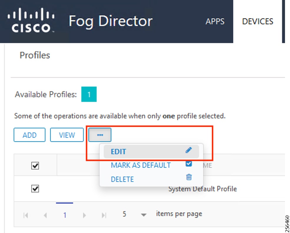
6.![]() From the Communication tab, provide the Proxy address as FND IP and Proxy port as 9094. Click Update to save the settings.
From the Communication tab, provide the Proxy address as FND IP and Proxy port as 9094. Click Update to save the settings.
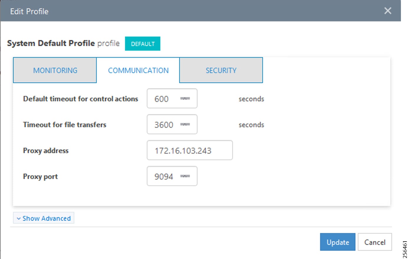
Application Installation
1.![]() Upload Edge Compute application in FD.
Upload Edge Compute application in FD.
Figure 216 Select Edge Compute Application Package
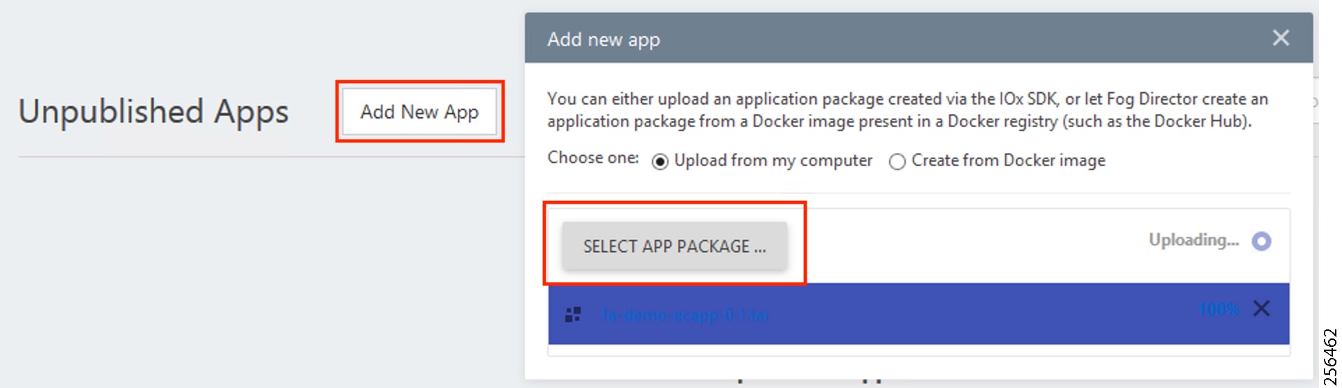
2.![]() To publish the application, click Publish.
To publish the application, click Publish.
Figure 217 Publish the Application
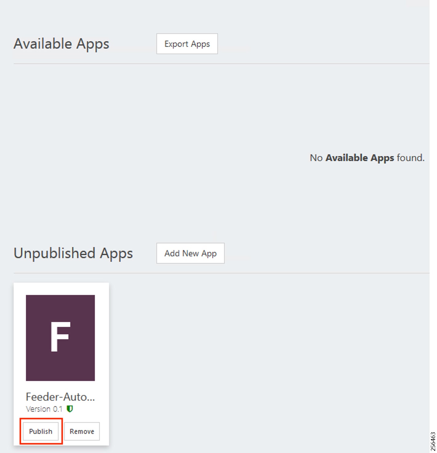
3.![]() To install the application, click the Application icon.
To install the application, click the Application icon.
Figure 218 Select the Edge Compute Application Package to Install
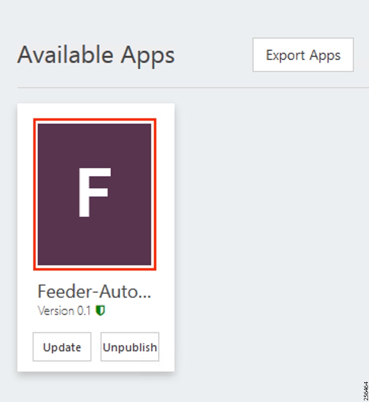
Figure 219 Install the Selected Edge Compute Application Package
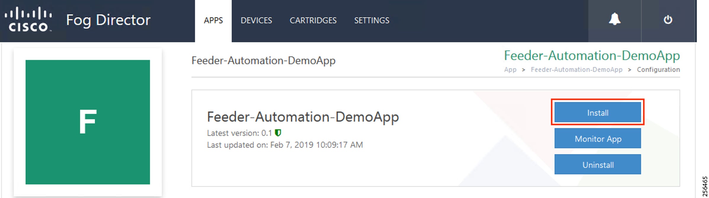
4.![]() Click Install to initiate the install of the application.
Click Install to initiate the install of the application.
5.![]() Select device(s) to install.
Select device(s) to install.
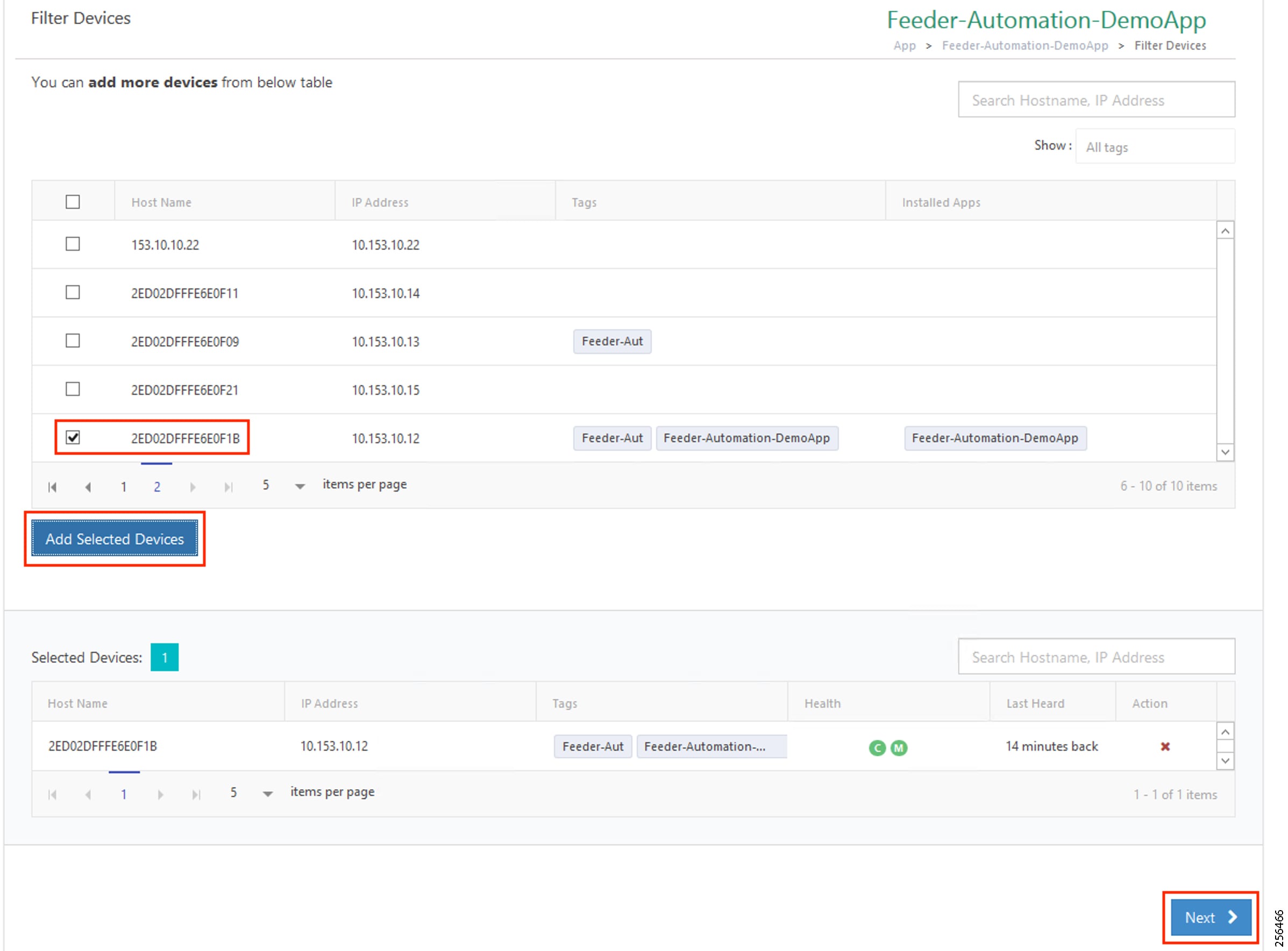
6.![]() Select all the devices on which the edge compute application needs to be installed.
Select all the devices on which the edge compute application needs to be installed.
Figure 221 Add Selected Device
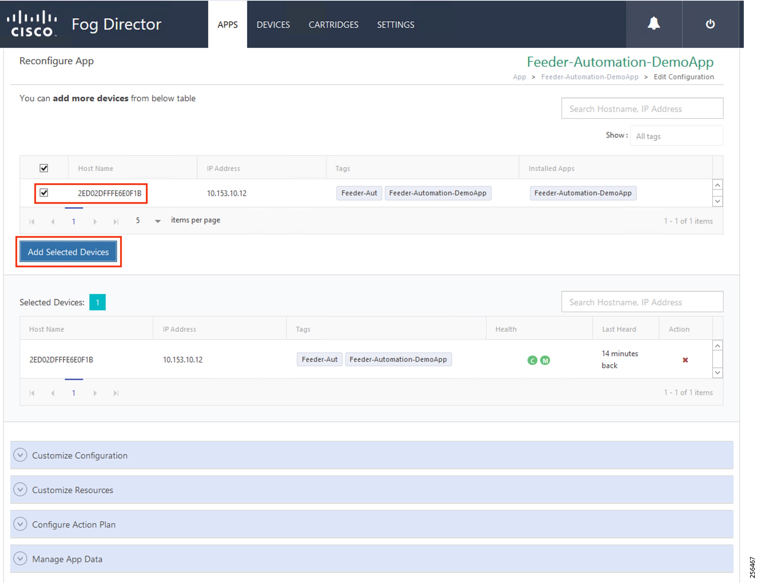
7.![]() Configure application parameters.
Configure application parameters.
Figure 222 Customize Application Configuration
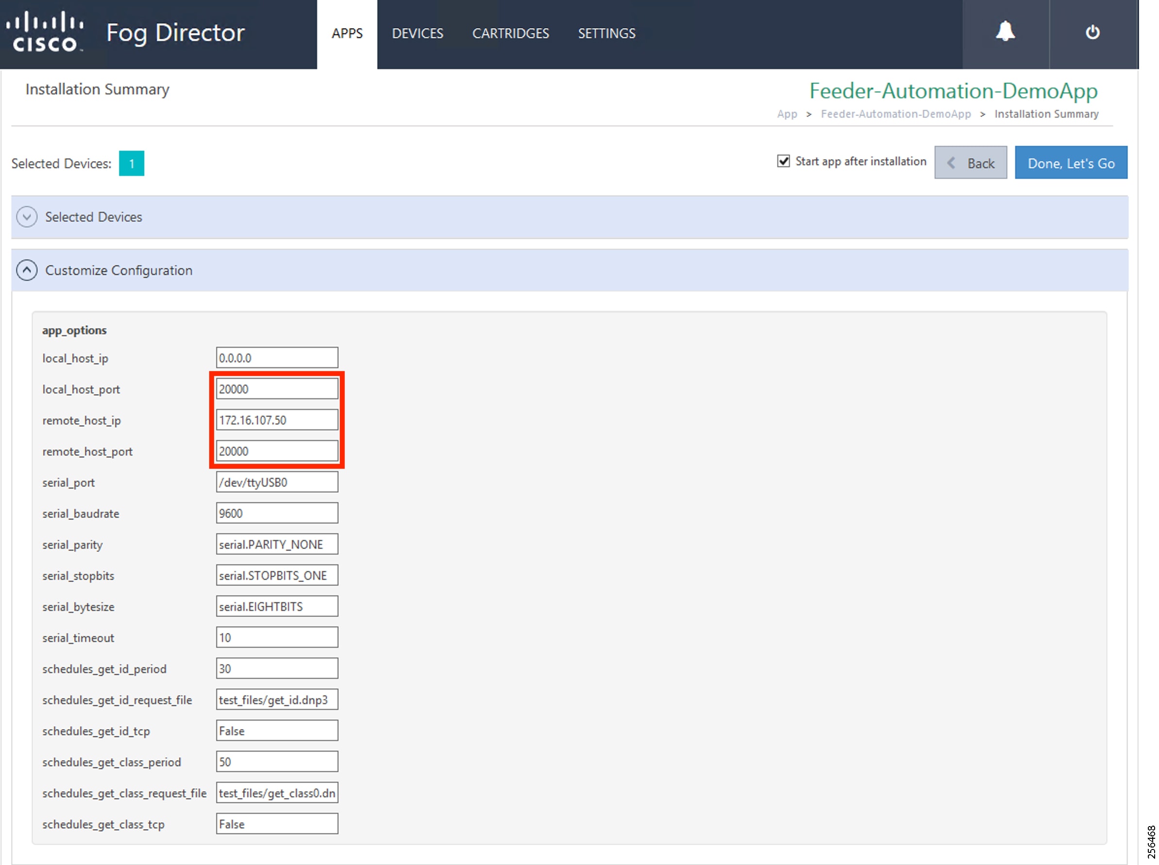
8.![]() Customize the SCADA Control Center IP address, DNP3 UDP port on Control Center, and Outstation/IED device.
Customize the SCADA Control Center IP address, DNP3 UDP port on Control Center, and Outstation/IED device.
Refer to Figure 203 for more details.
Figure 223 Edit Network Details
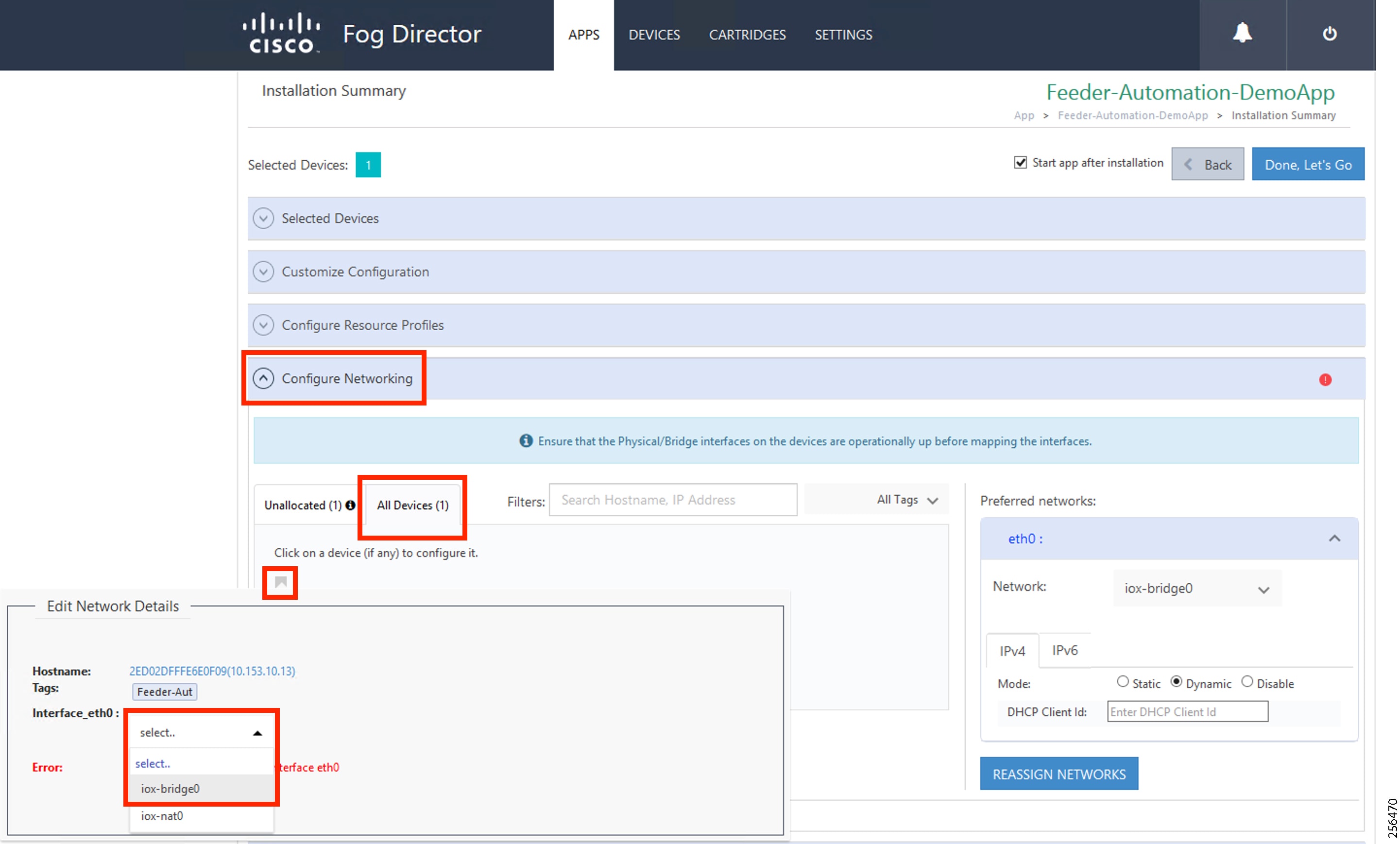
10.![]() Select the Network Mode as Bridge mode.
Select the Network Mode as Bridge mode.
11.![]() Configure the Edge Compute application IP.
Configure the Edge Compute application IP.
Figure 224 Configure Application IP Address
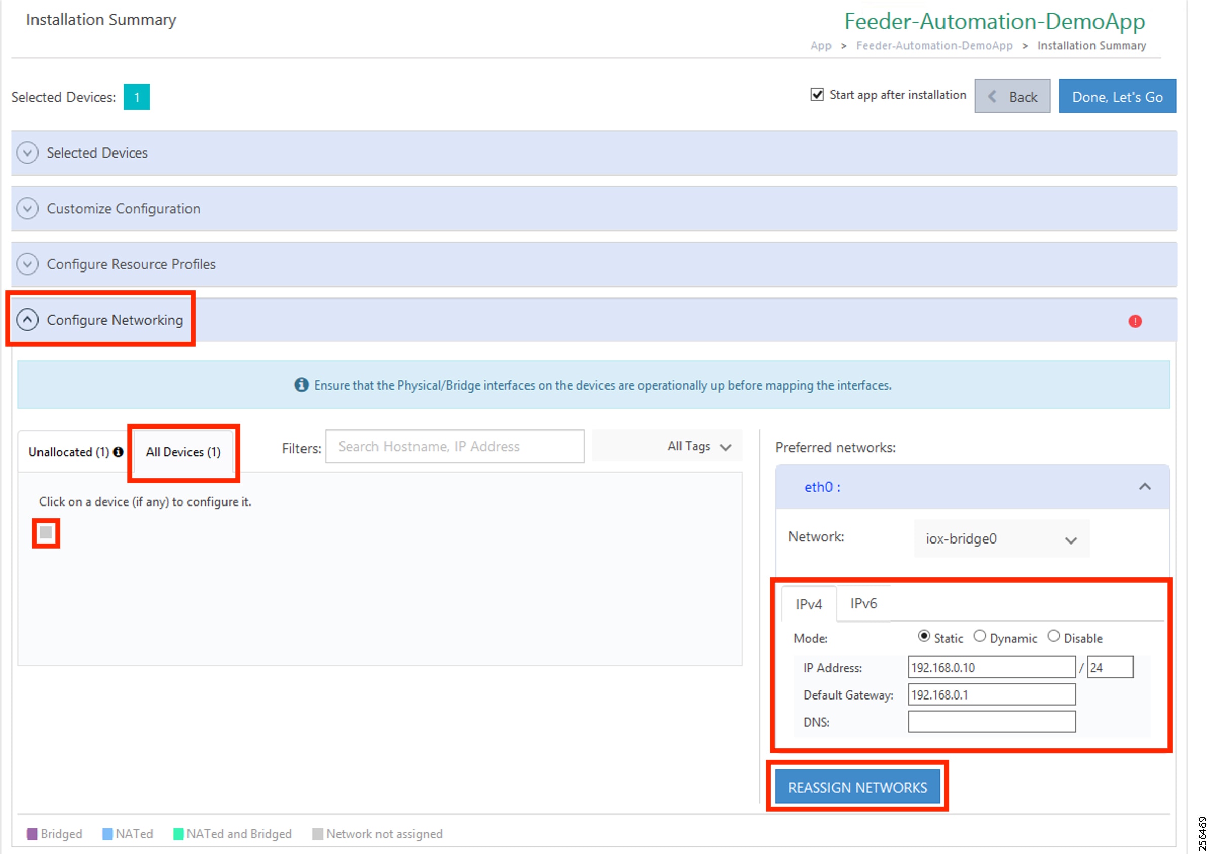
12.![]() Configure the Edge Compute application and its gateway.
Configure the Edge Compute application and its gateway.
13.![]() Configure the serial port.
Configure the serial port.
Figure 225 Configure Serial Port
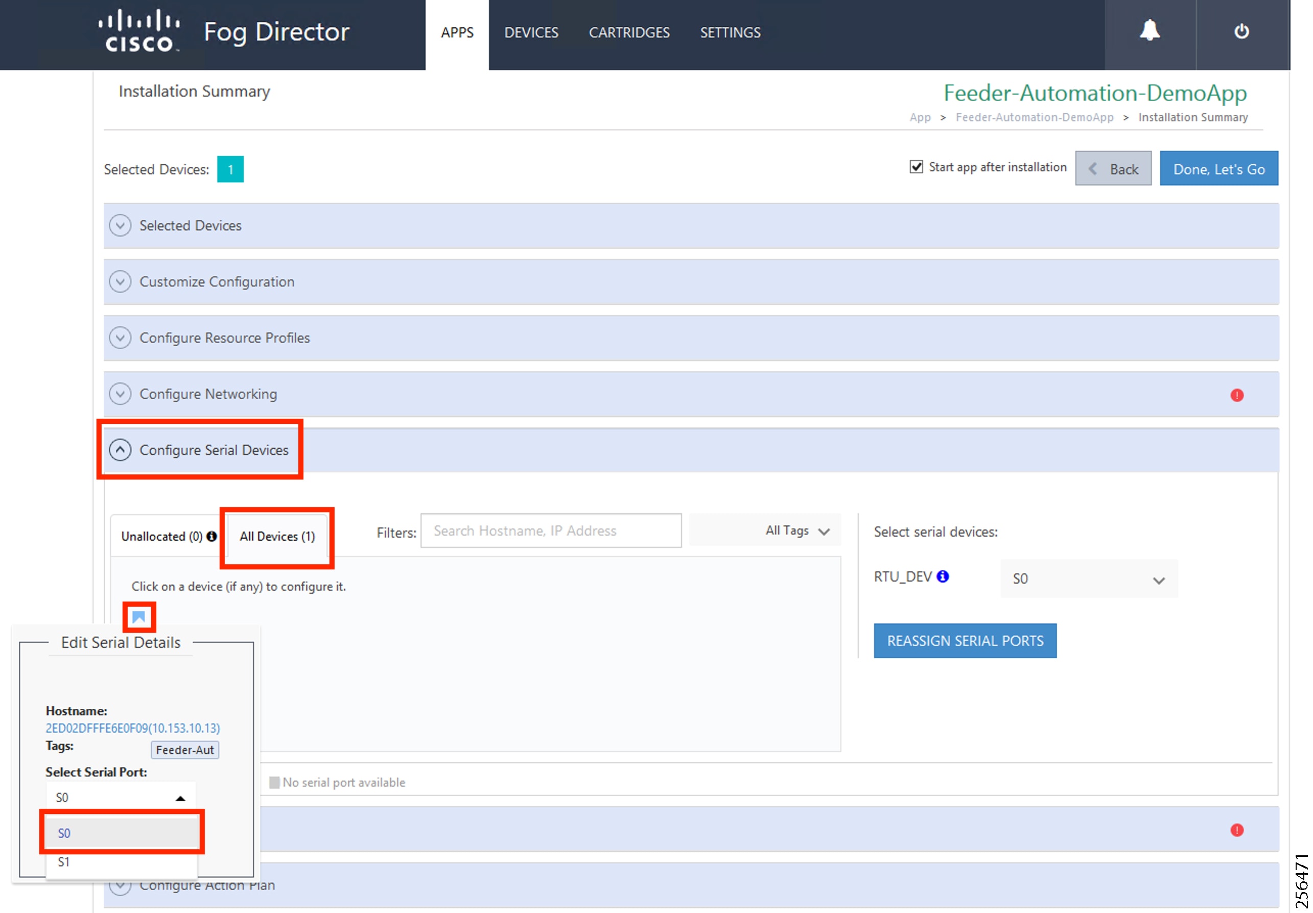
14.![]() Select the serial interface as S0.
Select the serial interface as S0.
15.![]() To install the application, click Install.
To install the application, click Install.
Figure 226 Application Installation Progress
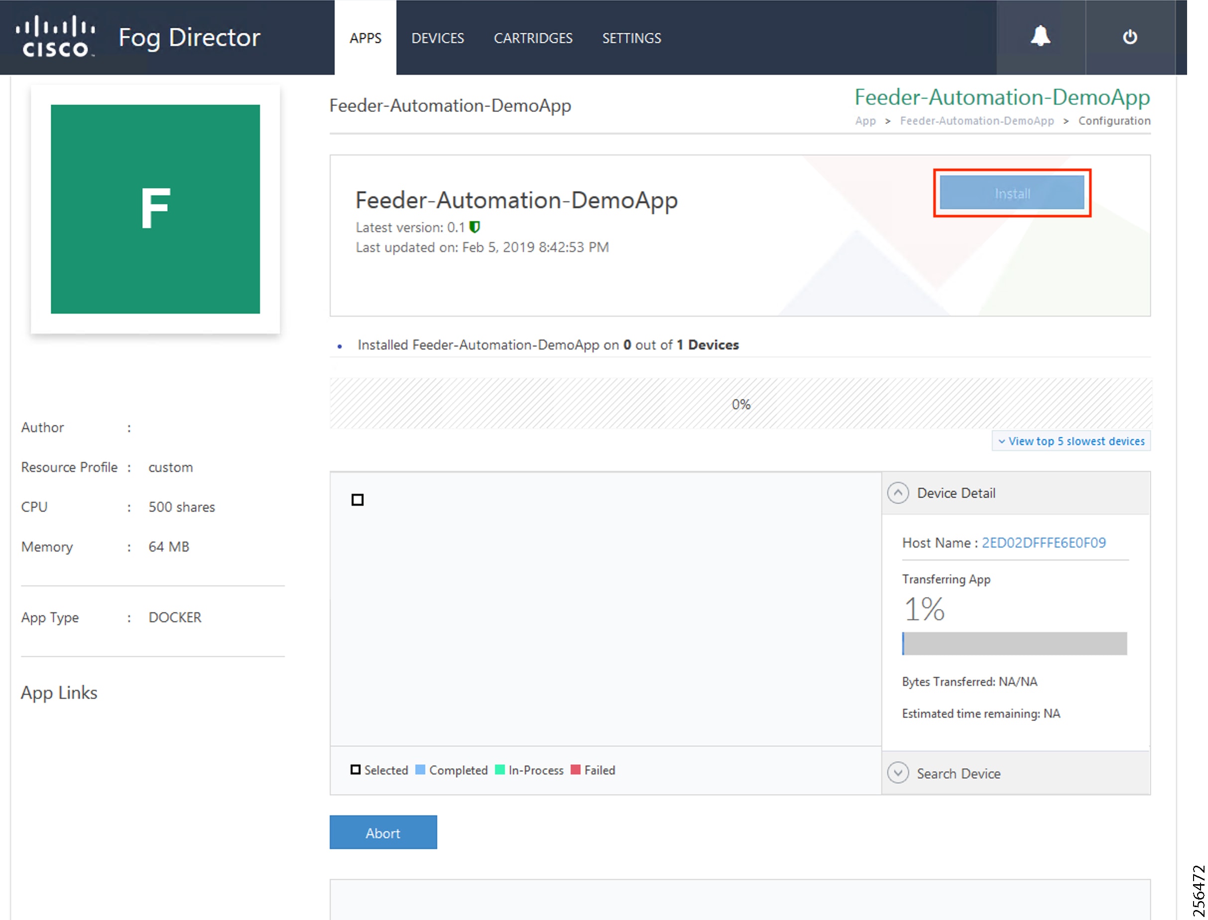
16.![]() Verify that the installation completed without any error.
Verify that the installation completed without any error.
Figure 227 Application Installation Complete
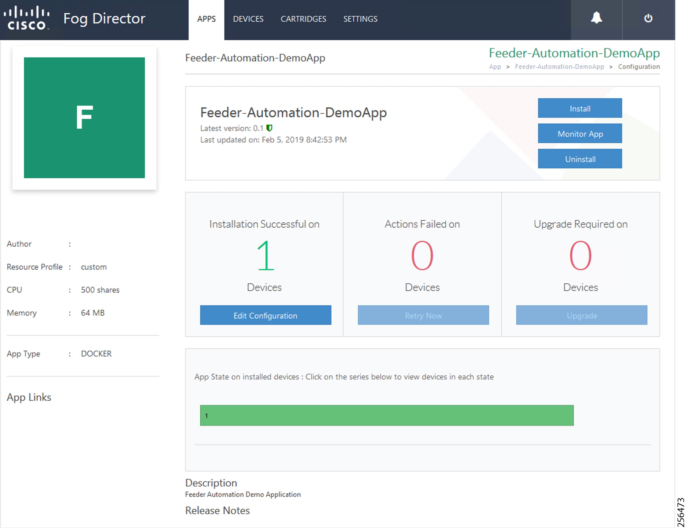
Stopping the Edge Compute Application
Figure 228 Application Monitor to Stop the Application
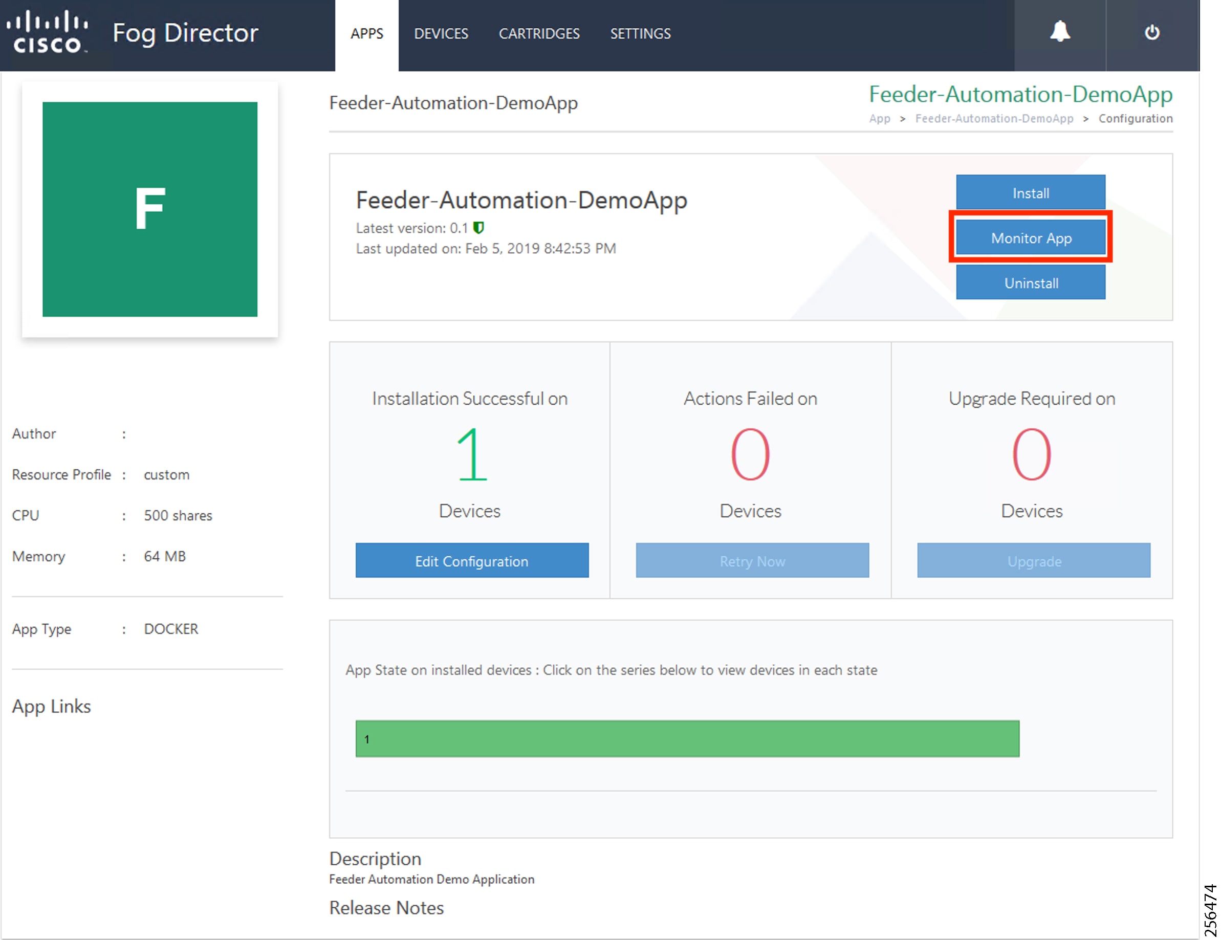
Figure 229 Stop the Application
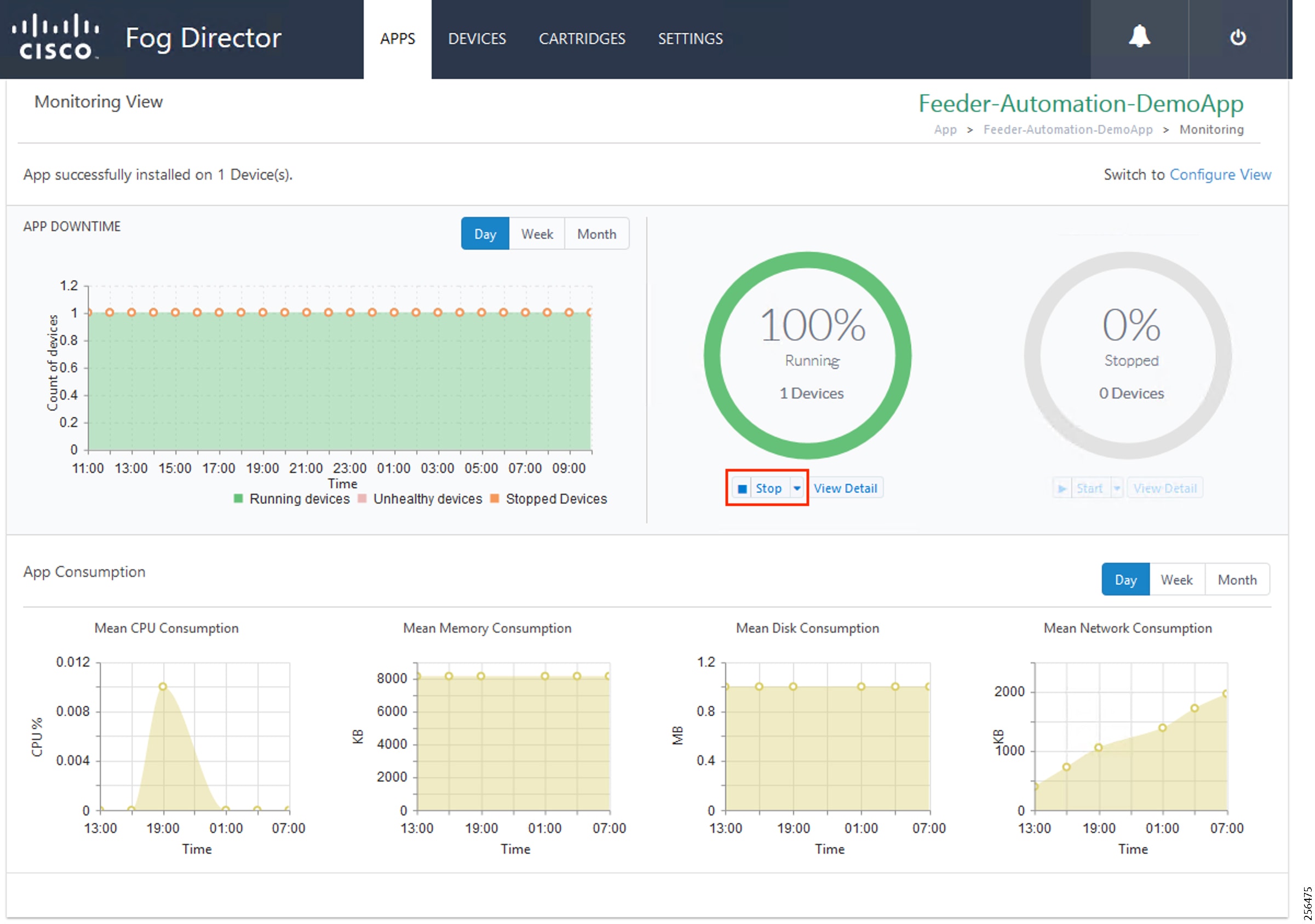
3.![]() Verify that the application is stopped.
Verify that the application is stopped.
Figure 230 Stopped State of the Application
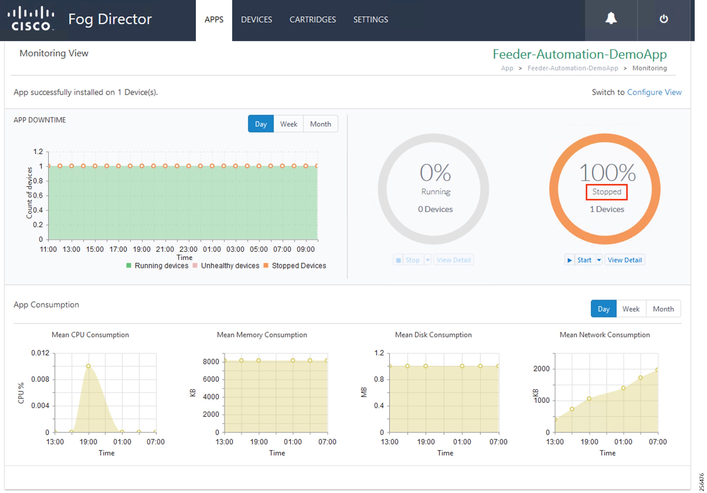
Starting the Edge Compute Application
Figure 231 Start the Application
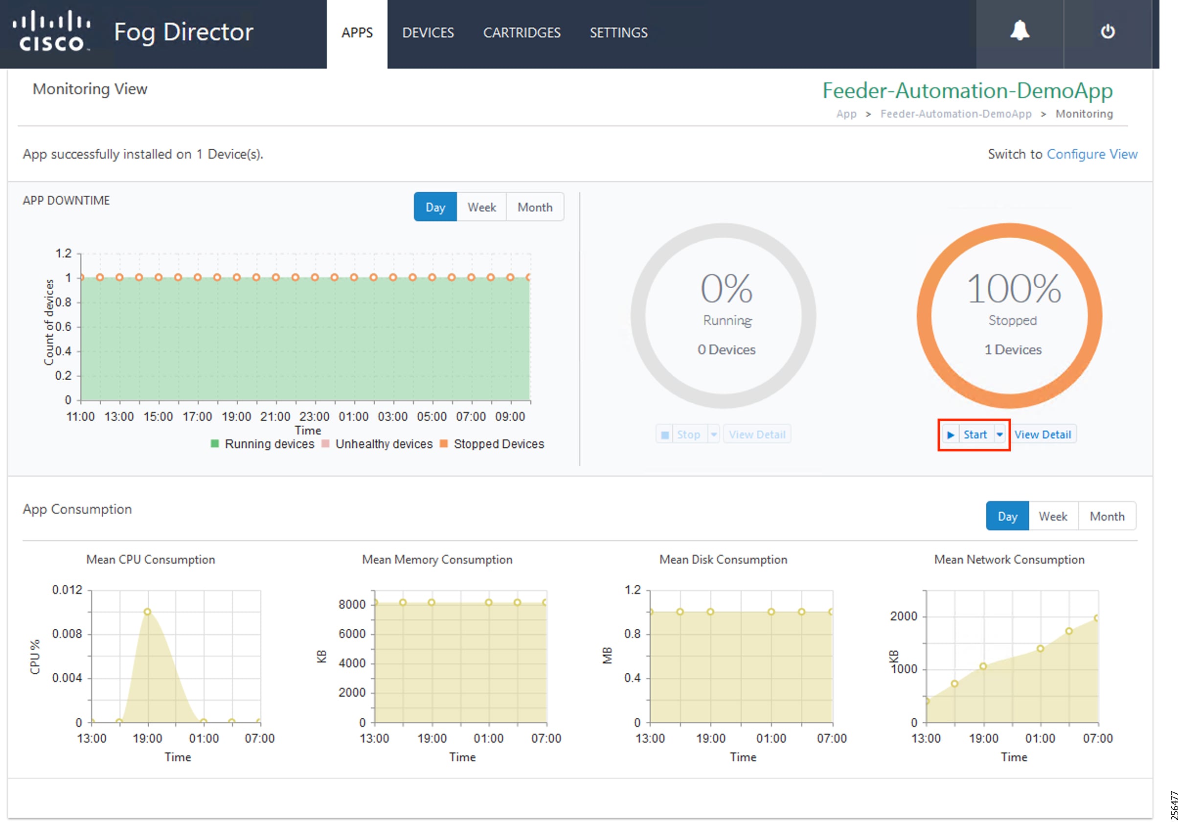
2.![]() Verify that the application is running.
Verify that the application is running.
Figure 232 Application Started

Uninstalling the Edge Compute Application
1.![]() Select the application to uninstall.
Select the application to uninstall.
Figure 233 Select the Application to Uninstall
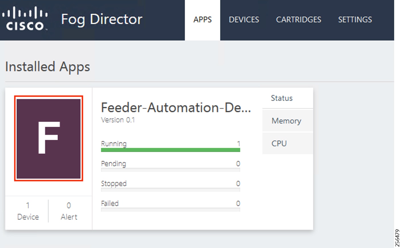
Figure 234 Uninstall the Application
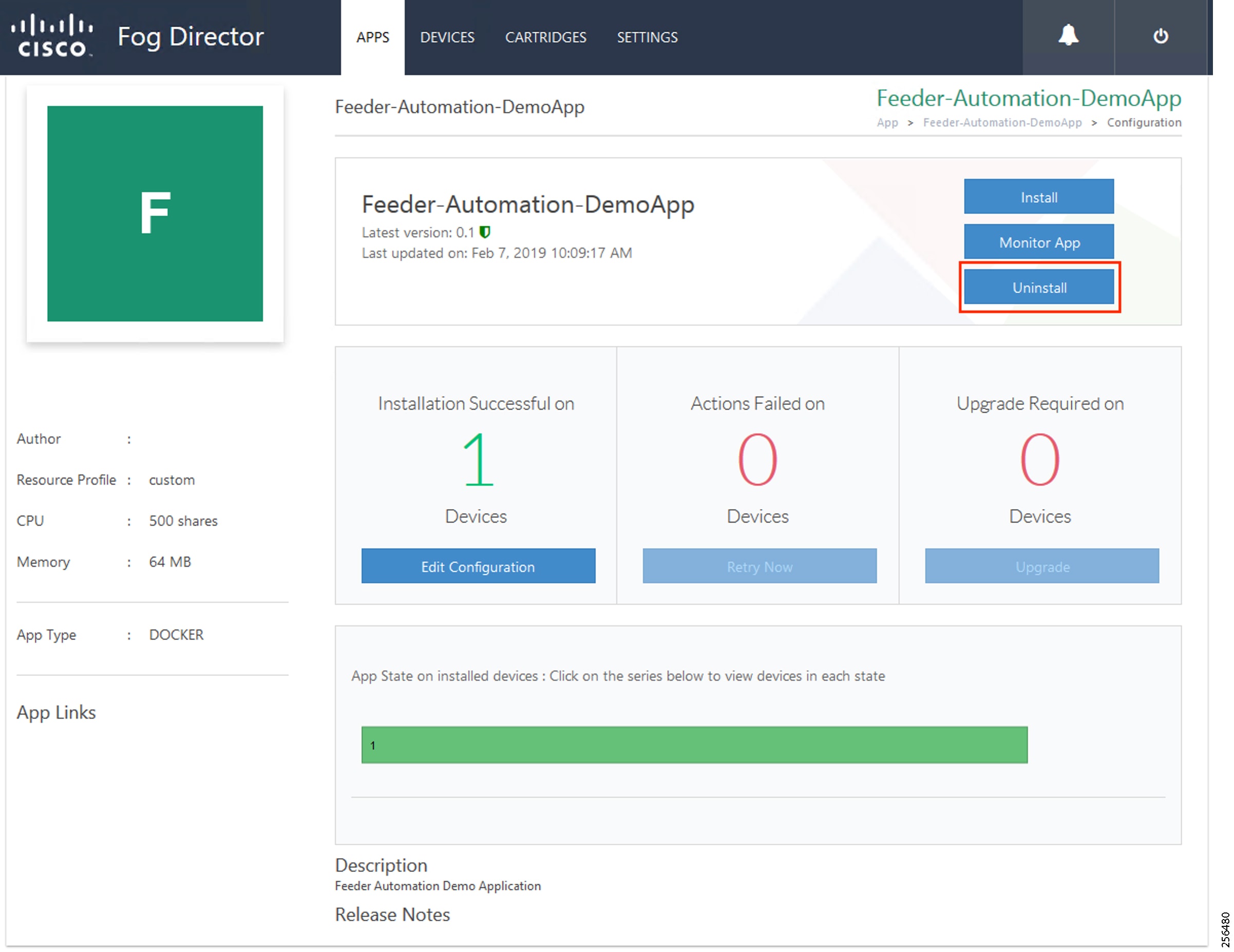
3.![]() Select the device on which the application should be uninstalled.
Select the device on which the application should be uninstalled.
Figure 235 Device Selection for Uninstalling the Application
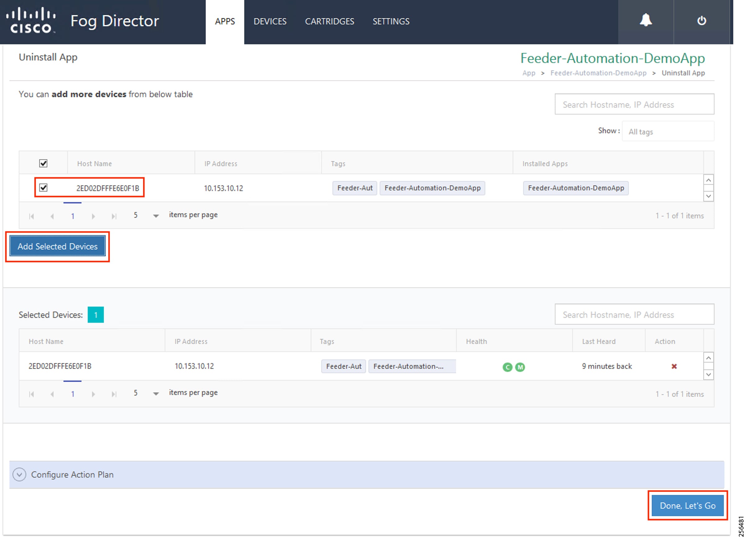
4.![]() Application uninstallation progress status.
Application uninstallation progress status.
Figure 236 Application Uninstallation Progress
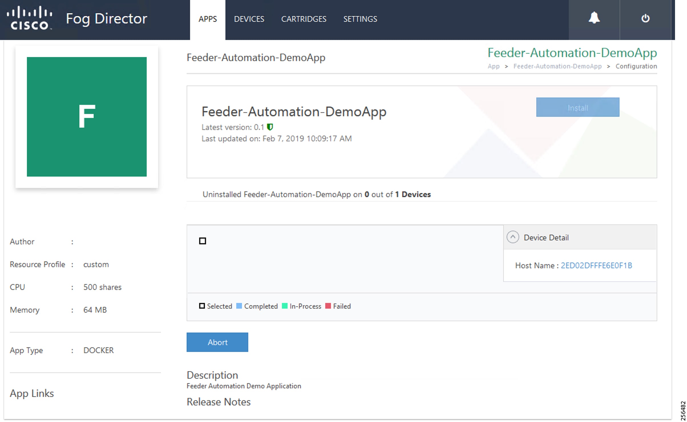
5.![]() Application uninstallation complete status.
Application uninstallation complete status.
Figure 237 Application Uninstallation Complete
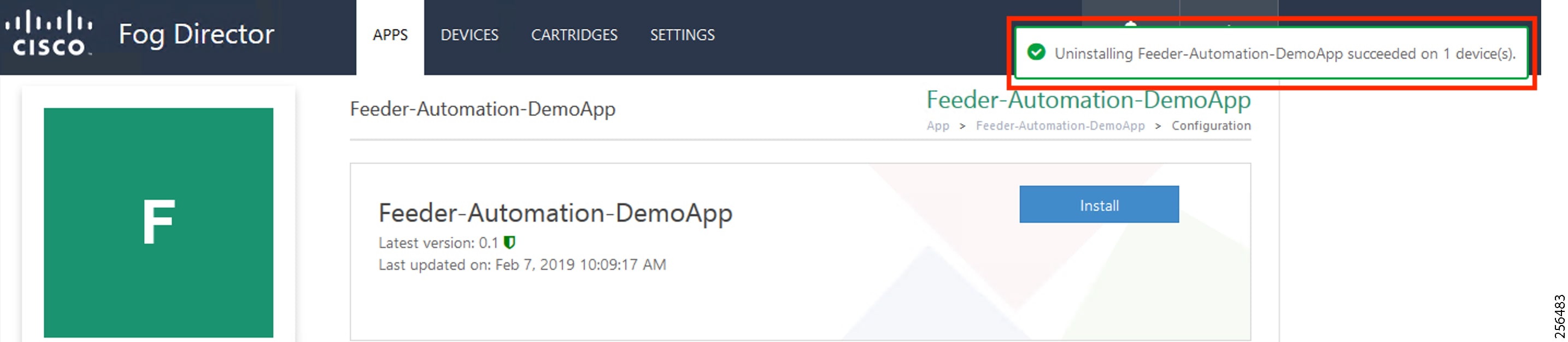
Figure 238 Application Removal
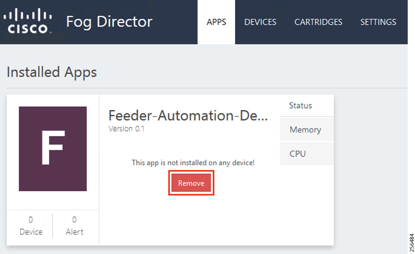
SCADA Traffic via Edge Compute Application
Unsolicited Reporting
1.![]() Verify that the unsolicited reports are sent from the IED to the Control Center periodically.
Verify that the unsolicited reports are sent from the IED to the Control Center periodically.
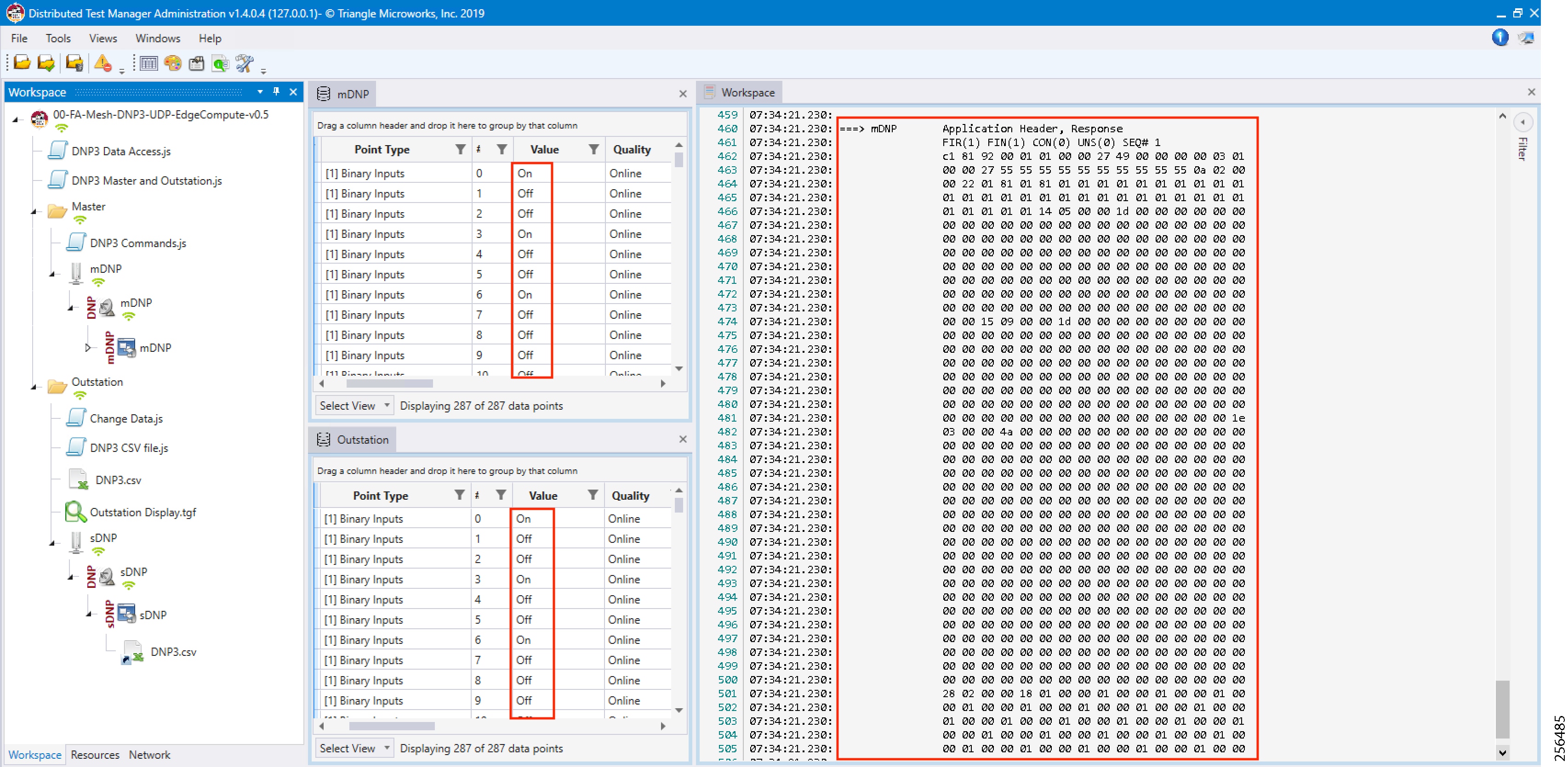
2.![]() Verify that the changed data on IED is reported to the Master by verifying that the Outstation point list (middle bottom window) matches the Master point list (middle top window).
Verify that the changed data on IED is reported to the Master by verifying that the Outstation point list (middle bottom window) matches the Master point list (middle top window).
Integrity Polling
1.![]() Right-click the Integrity Data Poll command.
Right-click the Integrity Data Poll command.
Figure 240 Execute Integrity Polling
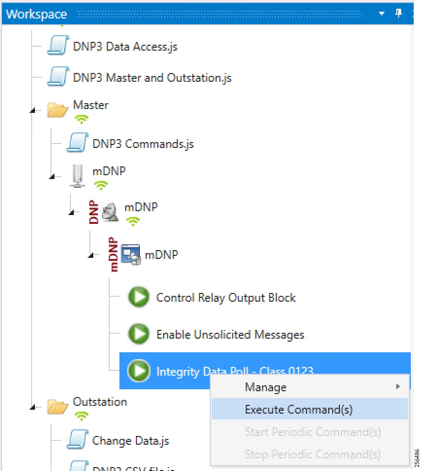
2.![]() Verify that the poll data from the IED to the Control Center is updated.
Verify that the poll data from the IED to the Control Center is updated.
Figure 241 Integrity Polling Response
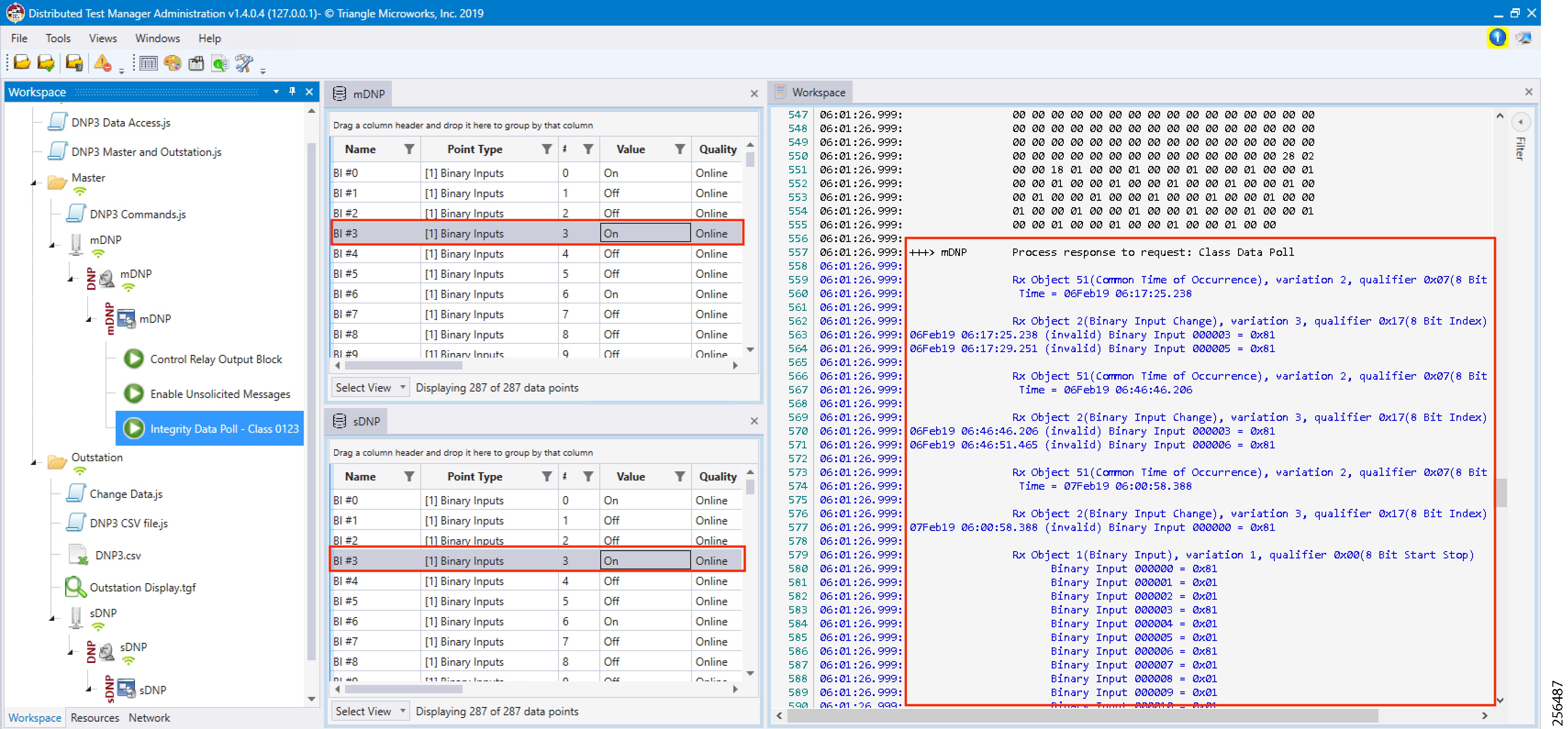
3.![]() Verify that the changed data on IED is reported to the Master by verifying the Outstation point list (middle bottom window) matches the Master point list (middle top window).
Verify that the changed data on IED is reported to the Master by verifying the Outstation point list (middle bottom window) matches the Master point list (middle top window).
Control Commands
1.![]() Right-click the Integrity Data Poll command.
Right-click the Integrity Data Poll command.
Figure 242 Execute Control Command
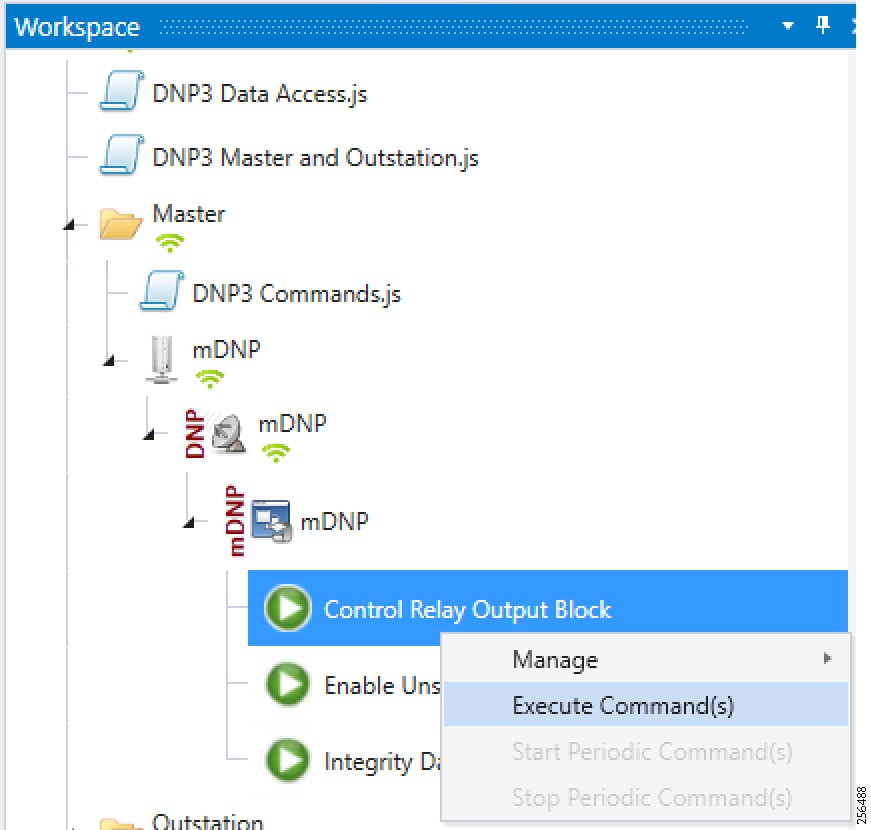
2.![]() Verify that the Control Command from the Control Center to the IED is updated.
Verify that the Control Command from the Control Center to the IED is updated.
Figure 243 Control Command Response
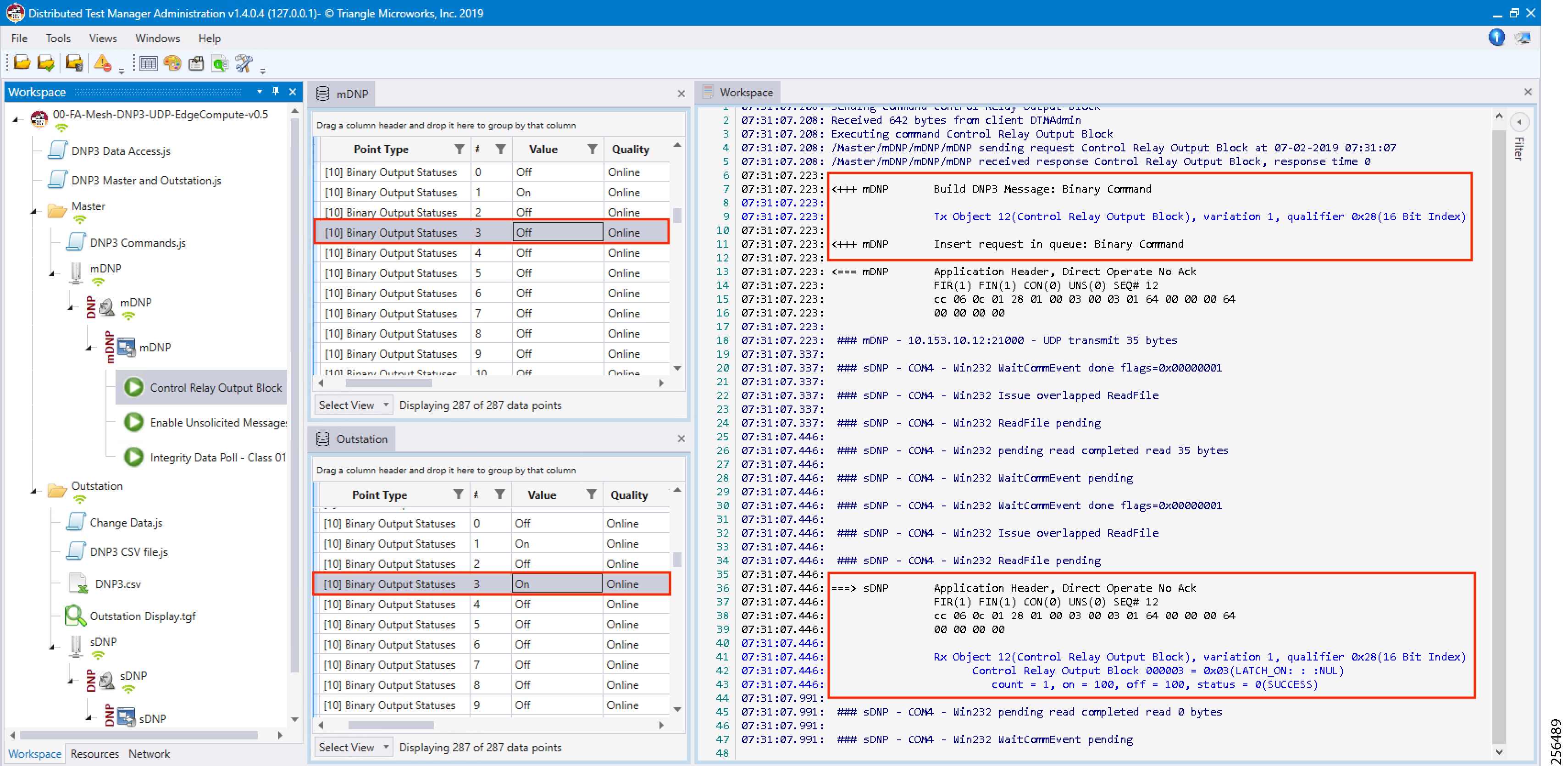
3.![]() Verify that the control command is being sent out from the Master (first red box in the right-most window) and also verify that the control command executed successfully on the IED/outstation by looking for status=SUCCESS in the second red box in the right-hand window.
Verify that the control command is being sent out from the Master (first red box in the right-most window) and also verify that the control command executed successfully on the IED/outstation by looking for status=SUCCESS in the second red box in the right-hand window.
IP Services
This section describes QoS policy and NAT configuration on both the DA Gateways and the Mesh DA Gateways. The first section covers IP services applicable to the DA Gateways and the second section describes IP services applicable to DA Mesh Gateways. The QoS policy is configured on the DA Gateways while on DA Mesh Gateways only DSCP marking is applicable. The configurations and the necessary steps have been illustrated with the help of screenshots.
IP Services on Cellular DA Gateways
Quality of Service
Quality of Service (QoS) refers to the ability of the network to provide priority service to selected network traffic. Improved and more predictable network service can be offered by:
■![]() Supporting dedicated bandwidth-that is, cellular links have different upload/download bandwidth/throughput
Supporting dedicated bandwidth-that is, cellular links have different upload/download bandwidth/throughput
■![]() Reducing loss characteristics-DA real-time traffic prioritization
Reducing loss characteristics-DA real-time traffic prioritization
■![]() Avoiding and managing network congestion-multi-services traffic
Avoiding and managing network congestion-multi-services traffic
■![]() Setting traffic priorities across the network-multi-services capabilities
Setting traffic priorities across the network-multi-services capabilities
QoS is a key feature when designing the multi-services Distribution Automation solution since traffic from AMI, DA, Remote Workforce, and network management use cases must be differentiated and prioritized. Estimated transport losses, delay, and jitter introduced by networking devices must be understood when forwarding sensitive data, particularly when a WAN backhaul link offers a limited amount of bandwidth.
In the case of dual-WAN interfaces with different bandwidth capabilities (that is, cellular), QoS policies must be applied to prioritize the traffic allowed to flow over these limited bandwidth links, to determine which traffic can be dropped, etc. A multi-services DA solution and QoS DiffServ can apply to traffic categorized as:
■![]() IPv4 Traffic-Distribution Automation (FLISR), protocol translation (RTU monitoring), and network management
IPv4 Traffic-Distribution Automation (FLISR), protocol translation (RTU monitoring), and network management
■![]() IPv6 Traffic-IPV6 IED AMI and network management
IPv6 Traffic-IPV6 IED AMI and network management
Figure 211 lists the different priorities among Distribution Automation traffic.
Figure 244 DA Traffic Priority Chart
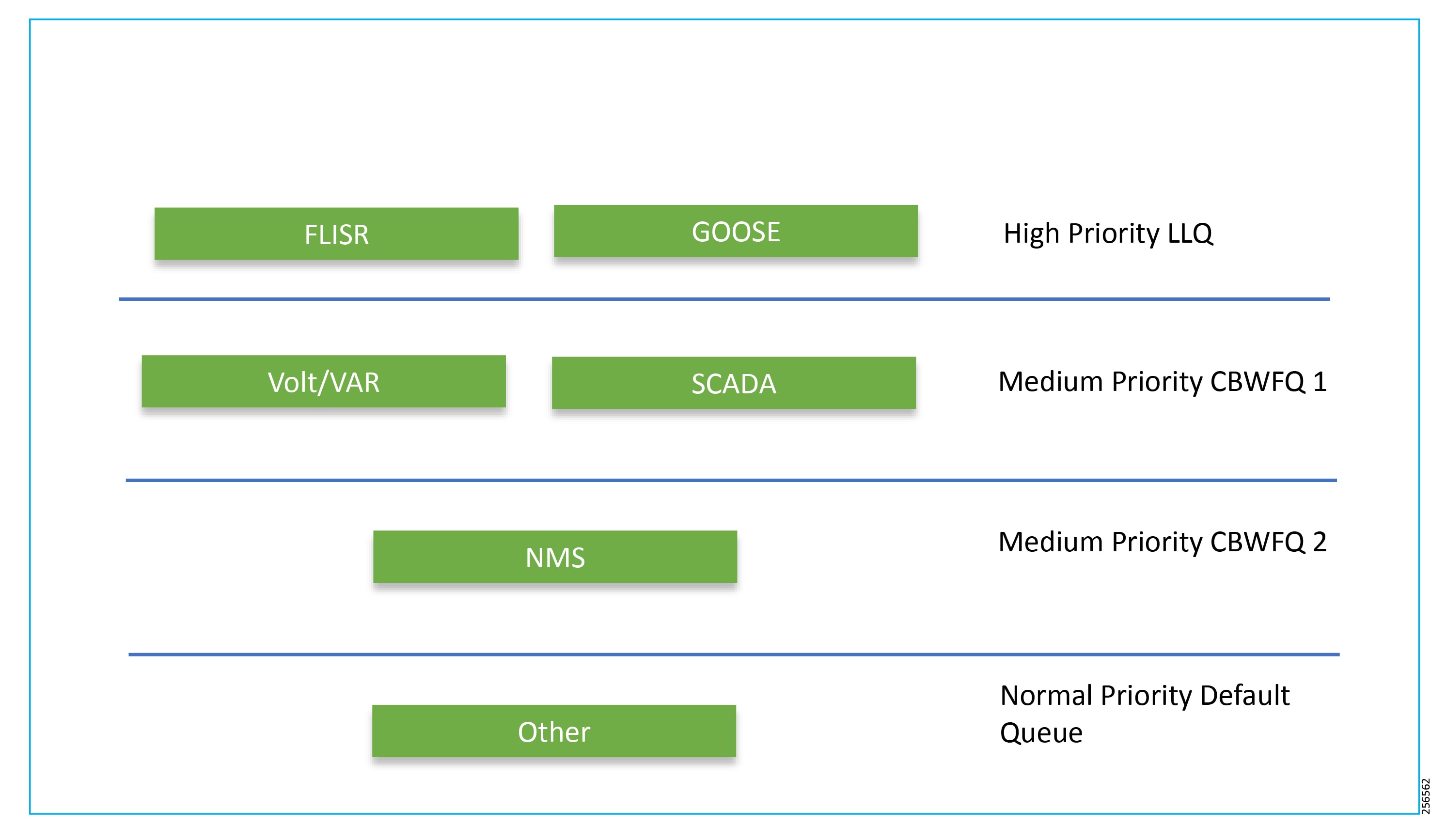
Following the IETF Differentiated Service model, the DA solution will deliver a service type that is based on the QoS specified by each packet. This specification can occur in different ways, for example, using the IP DSCP bit settings in IP packets or source and destination addresses. The QoS specification can be used to classify, mark, shape, and police traffic, and to perform intelligent queuing.
Cellular DA Gateways and FARs perform QoS actions on the Layer 3 (Cellular, Ethernet) interfaces. The sequencing of QoS actions on egress traffic is as follows:
Upstream QoS: DA IED to SCADA
The DA IEDs perform the marking functionality. If the IED does not have capability to mark the IP packets, the DA Gateway or SSR can perform the marking functionality. On egress WAN interface, queuing will be performed. High priority FLISR and GOOSE traffic will be assigned in Low Latency Queue. Medium priority traffic like Volt/VAR and MMS will be assigned in Class-Based Weighted Fair Queue 1, and IOT FND Network management traffic will be assigned in Class-Based Weighted Fair Queue 2. The rest of the traffic will be treated with normal priority and will be assigned to a default queue. All QoS is done based on DSCP marking.
Note: It is recommended to define queuing bandwidth as a remaining percentage instead of in values so that the same policy can be applied across Cellular or Ethernet backhaul interfaces.
Headend Router—The ASR 1000, which supports a rich QoS feature set from Cisco IOS, provides DoS protection for applications like the FND and SCADA. Refer to the latest documentation link for complete details:
■![]() https://www.cisco.com/c/en/us/products/collateral/routers/asr-1002- router/solution_overview_c22-449961.html
https://www.cisco.com/c/en/us/products/collateral/routers/asr-1002- router/solution_overview_c22-449961.html
Figure 245 Upstream QoS IED to SCADA
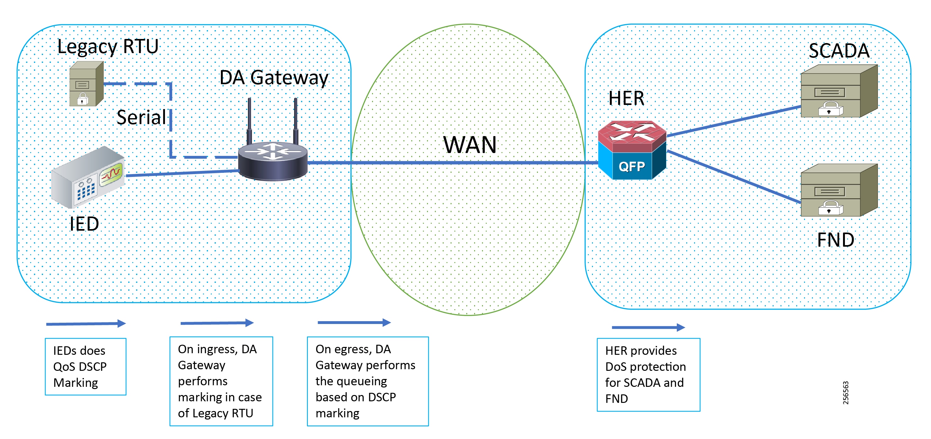
Note: If the IEDs don't have the capability to perform the marking or if the marking done by IED needs to remarked, then the MQC policy on Ethernet can re-mark the DSCP values for the incoming traffic.
Note: A sample configuration to mark traffic on Ethernet interface:
Raw Socket QoS Marking
If RTU is connected to DA Gateway via the R232 async serial interface and if the Raw Socket feature is enabled, marking will be enabled on the serial line.
Class-based policy is not supported on serial interfaces. The packets received on the serial interface should be marked on the corresponding line of the serial interface. The following configurations should be applied on the line interface:
After marking the packets from the serial interface, these marked packets can be prioritized at the WAN interface using the following class-map and policy-map. Since the SCADA traffic is encapsulated before it is sent out via the tunnel interface on the WAN interface, the QoS pre-classify command should be applied on the corresponding tunnel interface.
Queuing on DA Gateway WAN Port
Network Address Translation
The IoT Gateway is capable of supporting both NAT and non-NAT scenarios described in the Design Guide. The NAT scenario has been implemented in this Implementation Guide.
Note: This configuration is pushed as part of ZTD (during device registration phase). The FND leverages the SCADA Application Traffic Enablement profiles discussed in Appendix E: HER and CGR Configurations.
Note: The Loopback address is assigned to the IoT Gateway during the Tunnel provisioning phase of ZTD and it uniquely represents the IoT Gateway in the solution.
Figure 246 Network Address Translation
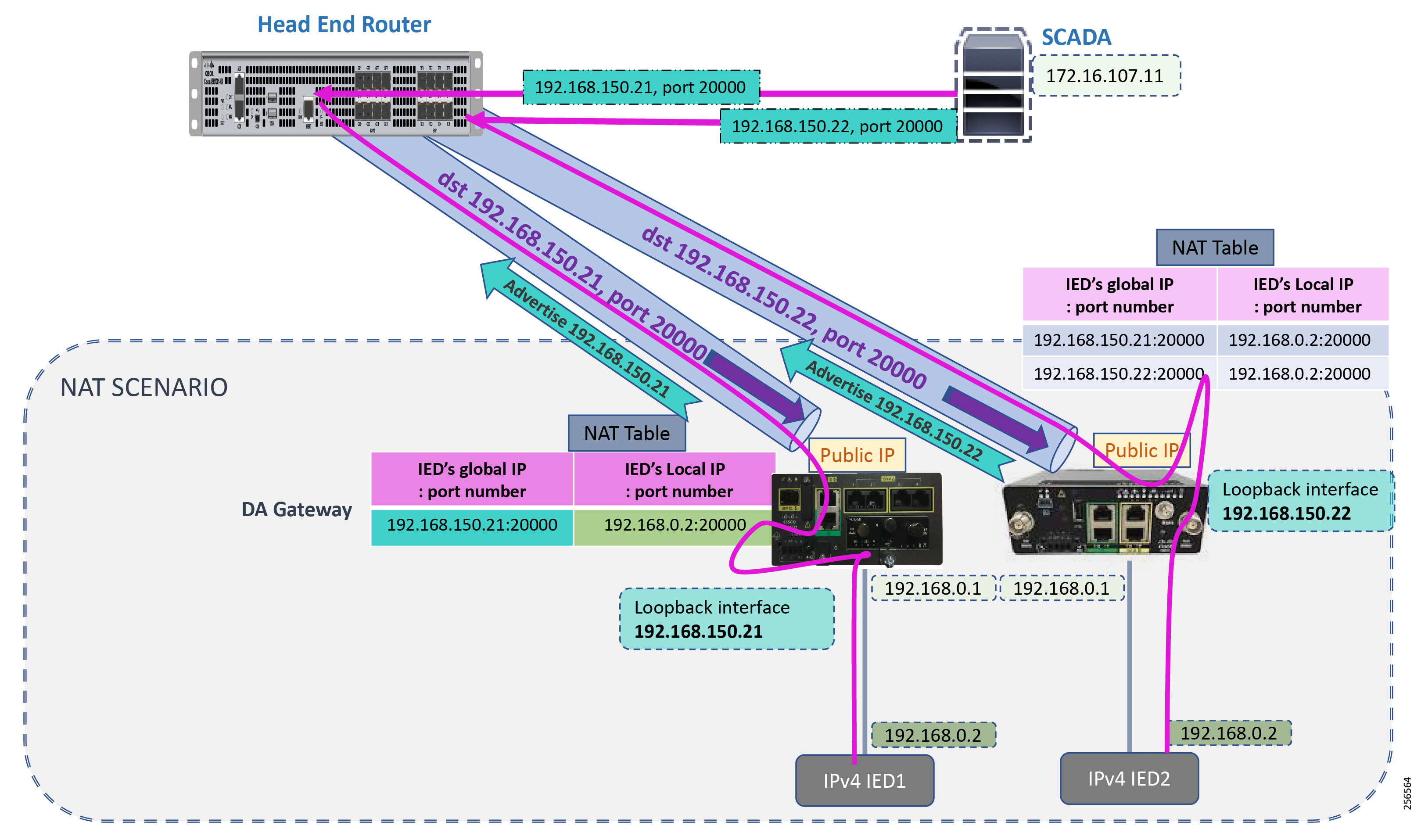
In Figure 213, the SCADA Master communicates with the IP address of the IoT Gateway (represented by its loopback address-for example, 192.168.150.21) on port number 20000.
Once the communication reaches the IoT Gateway, the NAT table is referenced for the IoT Gateway IP (for example, 192.168.150.21) and port 20000, and the IP address and port number of the IED is derived.
Communication is then forwarded to IED IP (192.168.0.2) on port 20000. In summary:
■![]() The SCADA communication on 192.168.150.21 on port 20000 is sent to IED1:20000.
The SCADA communication on 192.168.150.21 on port 20000 is sent to IED1:20000.
■![]() The SCADA communication on 192.168.150.22 on port 20000 is sent to IED2:20000.
The SCADA communication on 192.168.150.22 on port 20000 is sent to IED2:20000.
In Figure 213 above, the SCADA Master communicates with the IP address of the IoT Gateway (represented by its loopback address, for example, 192.168.150.21) on port number 20000.
Once the communication reaches the IoT Gateway, the NAT table is referenced for the IoT Gateway IP (for example, 192.168.150.21) and port 20000, and the IP address and port number of the IED is derived.
Communication is then forwarded to IED IP (192.168.0.2) on port 20000. In summary:
■![]() The SCADA communication on 192.168.150.21 on port 20000 is sent to IED1:20000.
The SCADA communication on 192.168.150.21 on port 20000 is sent to IED1:20000.
■![]() The SCADA communication on 192.168.150.22 on port 20000 is sent to IED2:20000.
The SCADA communication on 192.168.150.22 on port 20000 is sent to IED2:20000.
NAT on IR1101
The Layer 3 port connected to the IED is VLAN1, which should be enabled as a NAT-inside interface. The Layer 3 port providing connectivity to the control center is the FlexVPN IPSec Tunnel interface, which should be enabled as a NAT-outside interface.
Note: The Fast Ethernet ports of IR1101 are Layer 2. The Layer 3 IP address is configured on the VLAN interface:
NAT on IR807
The Layer 3 port connected to the IED is FastEthernet1, which should be enabled as a NAT-inside interface. The Layer 3 port providing connectivity to the control center is the FlexVPN IPSec Tunnel interface, which should be enabled as a NAT-outside interface.
Note: The Fast Ethernet ports of the IR807 are Layer 3:
NAT configurations on other IoT Gateway platforms (such as CGR1000 and IR8xx platforms) would be similar to the ones captured above.
IP Services on Mesh DA Gateways
QoS on IR510
QoS is an IOS feature that is applicable to DA gateways. QoS on Mesh gateways isn't MQC based and they support only DSCP marking of the packets. This DSCP marking is available to the user and can be applied to the Ethernet interface or the serial interfaces. The marking can be easily done from FND. The following subsections describe how to enable marking on both Ethernet and serial interfaces.
Marking Ethernet Traffic on IR510
Marking on Ethernet interface can be performed in two ways:
First, all the traffic that is being transmitted on the Ethernet interfaces can be marked:
1.![]() To mark all the packets, choose the CONFIG menu from the top bar.
To mark all the packets, choose the CONFIG menu from the top bar.
2.![]() Select Device Configuration from the drop-down config menu.
Select Device Configuration from the drop-down config menu.
3.![]() From the left menu, choose the ENDPOINT that was registered with FND.
From the left menu, choose the ENDPOINT that was registered with FND.
4.![]() Now select Edit Configuration Template, as shown in Figure 247. From the highlighted text, we can observe that DSCP settings can be changed according to the use case.
Now select Edit Configuration Template, as shown in Figure 247. From the highlighted text, we can observe that DSCP settings can be changed according to the use case.
5.![]() Once the DSCP marking has been defined, go to the push configuration and push the modified config to your device.
Once the DSCP marking has been defined, go to the push configuration and push the modified config to your device.
Figure 247 DSCP Marking on Ethernet Traffic
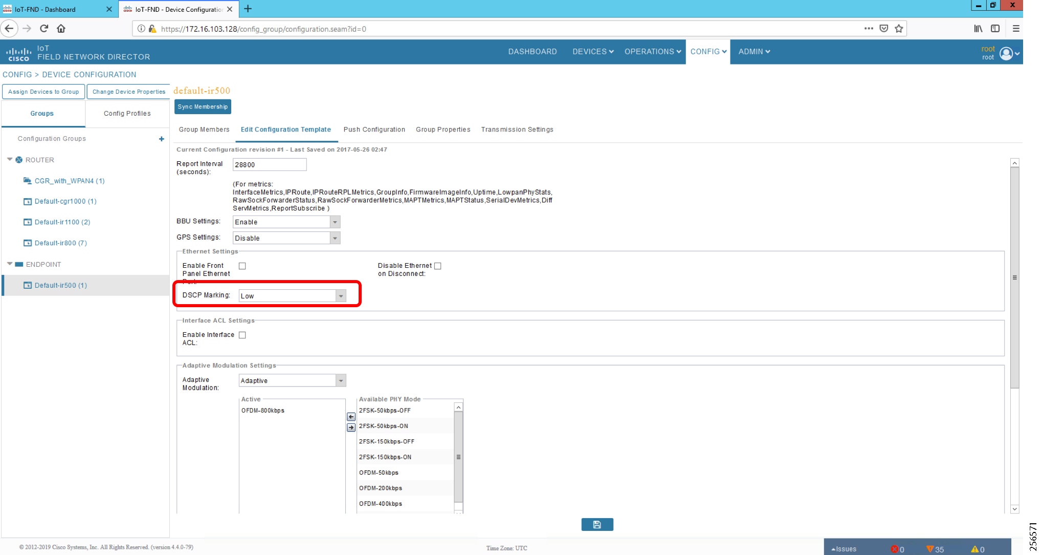
Second, the DSCP marking can be set for packets from a particular source:
1.![]() To mark the packets from a particular source, choose the CONFIG menu from the menu bar.
To mark the packets from a particular source, choose the CONFIG menu from the menu bar.
2.![]() Select Device Configuration from the drop-down config menu.
Select Device Configuration from the drop-down config menu.
3.![]() From the left menu, choose the Config Profiles tab.
From the left menu, choose the Config Profiles tab.
4.![]() Now select Default-DSCP-profile or create a profile with a user-defined name by clicking the '+' button.
Now select Default-DSCP-profile or create a profile with a user-defined name by clicking the '+' button.
5.![]() In the profile from the above step, add the source address and DSCP marking value. An example is shown in Figure 248.
In the profile from the above step, add the source address and DSCP marking value. An example is shown in Figure 248.
The Default-DSCP-Profile or User defined profile should be added to the configuration template for the specific ENDPOINT. This shown at the end of this section.
Figure 248 DSCP Marking on Ethernet Traffic from a Source Address
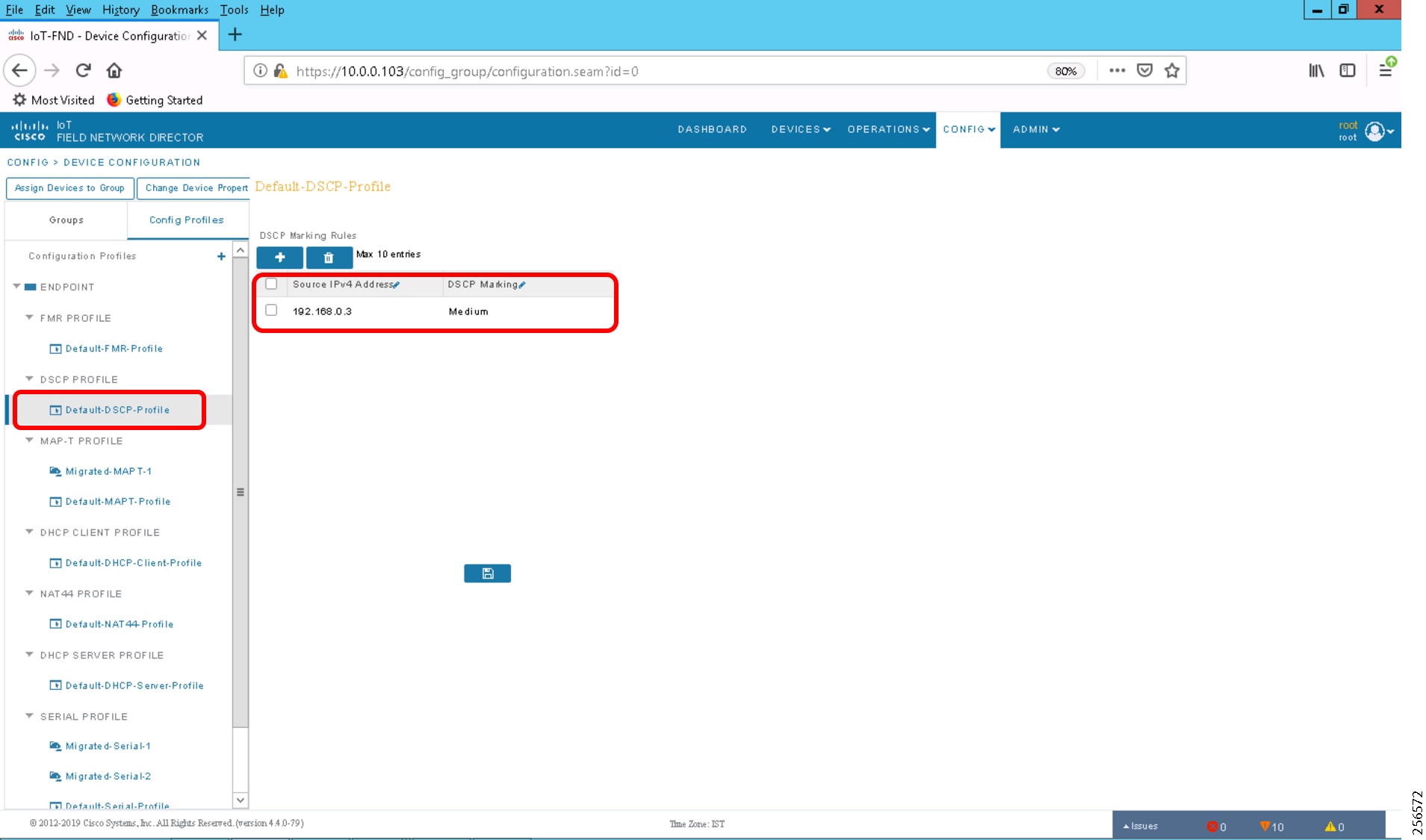
Marking Serial Traffic on IR510
Similar to the marking of packets over Ethernet interface, packets from serial interface can be marked. To mark the packets from serial interface, complete the following steps:
1.![]() Click CONFIG on the menu bar.
Click CONFIG on the menu bar.
2.![]() Select Device Configuration from the CONFIG drop-down menu.
Select Device Configuration from the CONFIG drop-down menu.
3.![]() Select the Config Profiles tab from the left menu.
Select the Config Profiles tab from the left menu.
4.![]() Select Migrated Serial-1 or create a serial profile by clicking the '+' button.
Select Migrated Serial-1 or create a serial profile by clicking the '+' button.
5.![]() Configure the Serial Properties and select the DSCP marking value, as shown in Figure 249.
Configure the Serial Properties and select the DSCP marking value, as shown in Figure 249.
6.![]() Save the profile and add it to the correct ENDPOINT.
Save the profile and add it to the correct ENDPOINT.
Figure 249 DSCP Marking on Serial Traffic
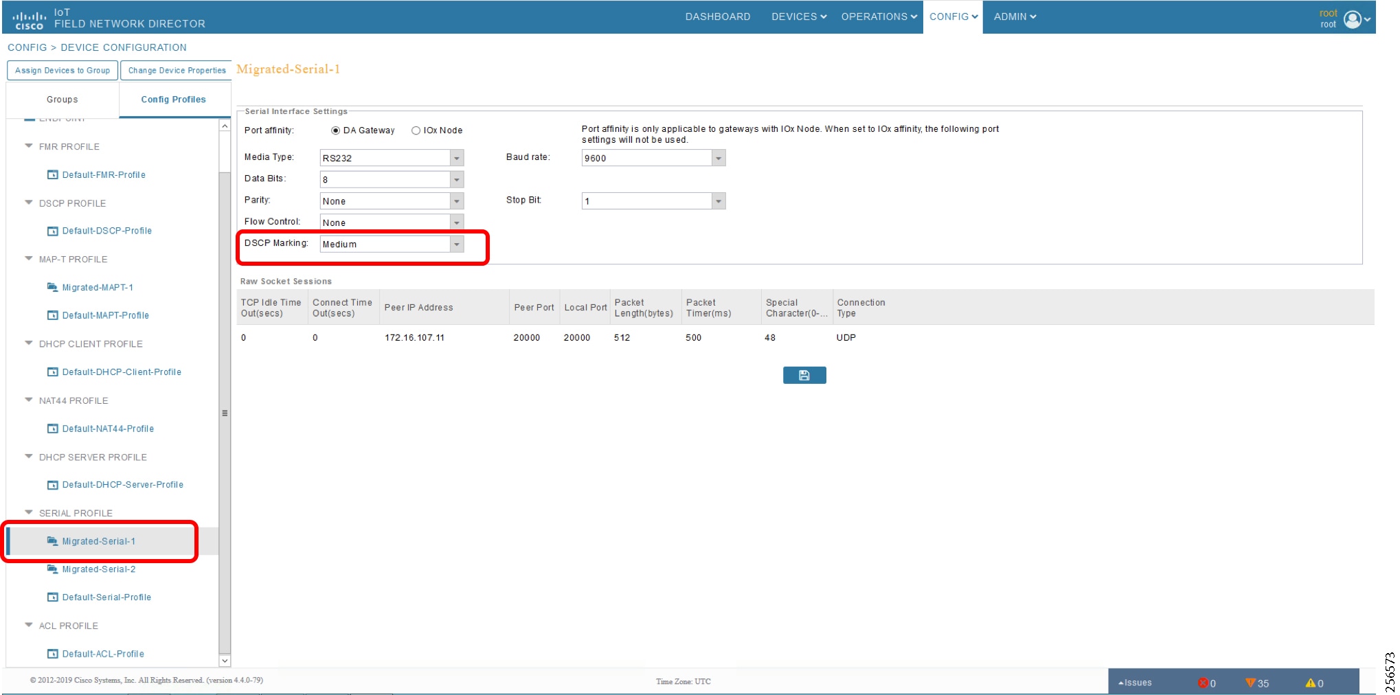
7.![]() The Config Profiles modified or created should be added to the correct ENDPOINT under the EDIT Configuration Template present in the Groups tab in the left menu.
The Config Profiles modified or created should be added to the correct ENDPOINT under the EDIT Configuration Template present in the Groups tab in the left menu.
8.![]() Scroll under the Edit Configuration Template.
Scroll under the Edit Configuration Template.
9.![]() Add the Ethernet DSCP marking profile, serial profile, and any other profiles required under the respective sections. The highlighted part in Figure 250 shows the profiles that are added in the respective fields.
Add the Ethernet DSCP marking profile, serial profile, and any other profiles required under the respective sections. The highlighted part in Figure 250 shows the profiles that are added in the respective fields.
10.![]() After adding the Config Profiles, from Push Configuration, push the configs to the Mesh DA Gateway.
After adding the Config Profiles, from Push Configuration, push the configs to the Mesh DA Gateway.
Figure 250 Adding Config Profiles in Edit Configuration Template
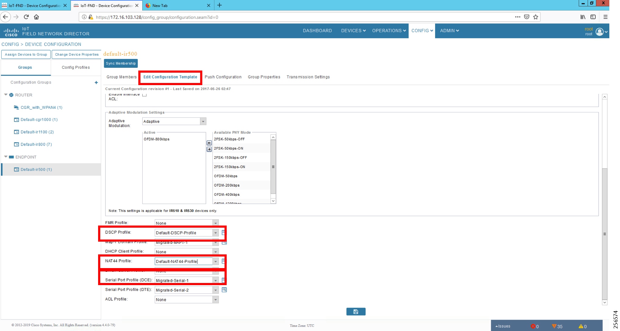
NAT on IR510
NAT is required on the IR510. The IEDs are connected to the IR510 using a private IP addresses. These private addresses are not reachable from the Control Center. Therefore, the NAT-44 profile in the Config Profiles need to be set and pushed to the IR510 for the devices to be reachable from the Control Center.
To configure a NAT-44 profile, complete the following steps:
Note: Private IP addresses are considered so that all the IEDs could be configured with same IPv4 address 192.168.0.3, which causes the operational simplicity.
1.![]() Select CONFIG from the Menu bar.
Select CONFIG from the Menu bar.
2.![]() Select Device Configuration from the CONFIG menu bar.
Select Device Configuration from the CONFIG menu bar.
3.![]() Select Config Profiles from the left menu.
Select Config Profiles from the left menu.
4.![]() Select Default NAT-44 profile or create a user-defined NAT-44 profile by clicking the '+' button.
Select Default NAT-44 profile or create a user-defined NAT-44 profile by clicking the '+' button.
5.![]() Add the source address and the respective source and destination port numbers for NAT to be configured on the IR510.
Add the source address and the respective source and destination port numbers for NAT to be configured on the IR510.
6.![]() Save the profile and add the profile in the EDIT Configuration Template of the correct ENDPOINT, as shown in the previous subsection.
Save the profile and add the profile in the EDIT Configuration Template of the correct ENDPOINT, as shown in the previous subsection.
Figure 251 Modifying Default NAT-44 Profile
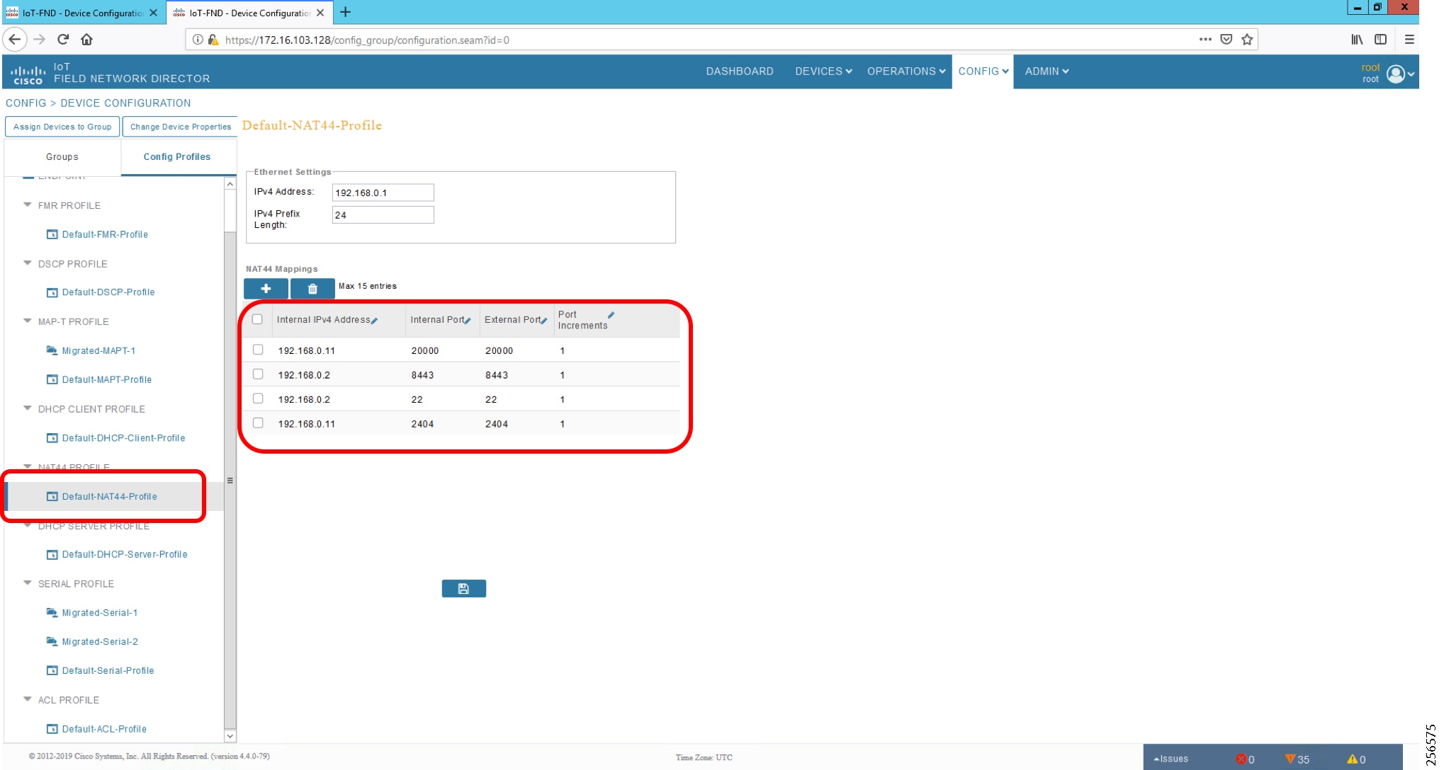
NTP
Services running on the FAN require time synchronization. The time synchronization for DA Gateways and Mesh DA Gateways are pushed from the FND while tunnel provisioning and Mesh Gateway registration occurs. For headend components such as the RA, CA, and FND, we use HER as the NTP server.
The NTP server on the HER is configured using the following command:
Note: The above command, which is part of ZTD process, is for reference only.
A similar command is used on DA gateways for time synchronization.
Appendix A: PnP Profiles
This appendix includes the following major topics:
■![]() Bootstrapping Template for IPv4 Network
Bootstrapping Template for IPv4 Network
■![]() Bootstrapping Template for IPv6 Network
Bootstrapping Template for IPv6 Network
■![]() Bootstrapping Template for Provisioning and ZTD at the Deployed Location
Bootstrapping Template for Provisioning and ZTD at the Deployed Location
Bootstrapping Template for IPv4 Network
Bootstrapping of the IoT Gateways that would NOT be deployed behind the NAT
These substitutions needs to be performed in the following bootstrapping template:
■![]() fingerprint 'CFA2613029B11E461430A2DC5F624147CCEE6469' must be replaced by the fingerprint of the RSA CA server that issues the certificate to the FND, TPS and FAR.
fingerprint 'CFA2613029B11E461430A2DC5F624147CCEE6469' must be replaced by the fingerprint of the RSA CA server that issues the certificate to the FND, TPS and FAR.
Bootstrap Profile Name: IPv4-BOOTSTRAP
Bootstrapping of IoT Gateways that would be Deployed behind NAT
These substitutions need to be performed in the following bootstrapping template:
■![]() fingerprint 'CFA2613029B11E461430A2DC5F624147CCEE6469' must be replaced by the fingerprint of the RSA CA server that issues the certificate to the FND, TPS and FAR.
fingerprint 'CFA2613029B11E461430A2DC5F624147CCEE6469' must be replaced by the fingerprint of the RSA CA server that issues the certificate to the FND, TPS and FAR.
Bootstrap Profile Name: IPv4-BOOTSTRAP-NAT
Bootstrapping Template for IPv6 Network
Bootstrapping of the IoT Gateways that would NOT be deployed behind the NAT
These substitutions need to be performed in the following bootstrapping template:
■![]() fingerprint 'CFA2613029B11E461430A2DC5F624147CCEE6469' must be replaced by the fingerprint of the RSA CA server that issues the certificate to the FND, TPS and FAR.
fingerprint 'CFA2613029B11E461430A2DC5F624147CCEE6469' must be replaced by the fingerprint of the RSA CA server that issues the certificate to the FND, TPS and FAR.
Bootstrap Profile Name: IPv6-BOOTSTRAP
Bootstrapping Template for Provisioning and ZTD at the Deployed Location
Bootstrapping of the IoT Gateways
These templates are used when the bootstrapping location and deployment location are the same. No manual intervention is need. Once the device is powered with a SIM card inserted, bootstrapping should begin and push the configuration from FND. The following template is an example of the template validated for IR1101. The template can be used for other platforms with minor changes such as the cellular interface.
Appendix B: FND Zero Touch Deployment Profiles
This appendix includes the following major topics:
■![]() Tunnel Group for IPv6 Network
Tunnel Group for IPv6 Network
Tunnel Provisioning Profiles
The Tunnel Provisioning Profile could also be referred to as the "Tunnel Group." For steps to create a new Tunnel group, please refer to the "Creating Tunnel Groups" section of the Cisco IoT FND guide.
Once the tunnel group is created, move the IoT Gateways under the appropriate "Tunnel Group." For steps, please refer to the "Moving FARs to another group" section of the Cisco IoT FND guide.
Tunnel Group for IPv4 Network
Note: To have the IoT Gateway operate in Dual Control Center scenarios, populate the fields for tunnelSrcInterface2 and IPSecTunnelDestAddr2. Leave them empty for single control center scenarios.
Note: Substitute the IP address with your FND IP address for fnd.ipg.cisco.com in the following template:
For FARs running IOS, configure a FlexVPN client in order to establish secure communications to the HER. This template expects that the HER has been appropriately pre-configured as a FlexVPN server:
Configure a Loopback0 interface for the FARL
If the loopback interface IPv4 address property has been set on the CGR, configure the interface with that address. Otherwise, obtain an address for the interface now using DHCP:
Obtain an IPv4 address that can be used for this FAR's Loopback interface. The template API provides methods for requesting a lease from a DHCP server. The IPv4 address method requires a DHCP client ID and a link address to send in the DHCP request. The third parameter is optional and defaults to "IoT-FND." This value is sent in the DHCP user class option. API also provides the method "dhcpClientId," which takes a DHCPv6 Identity association identifier (IAID) and a DHCP Unique IDentifier (DUID) and generates a DHCPv4 client identifier as specified in RFC 4361. This provides some consistency in how network elements are identified by the DHCP server.
If the loopback interface IPv6 address property has been set on the CGR, configure the interface with that address. Otherwise, obtain an address for the interface now using DHCP:
Obtain an IPv6 address that can be used to for this FAR's loopback interface. The method is similar to the one used for IPv4, except clients in DHCPv6 are directly identified by their DUID and IAID. IAIDs used for IPv4 are separate from IAIDs used for IPv6, so we can use zero for both requests:
Default to using FlexVPN for the tunnel configuration of FARs running IOS.
FlexVPN certificate map that matches if the peer (HER) presents a certificate whose issuer common name contains the string given in the FAR property certIssuerCommonName:
IPv4 ACL, which specifies the route(s) FlexVPN will push to the HER. We want the HER to know the route to the CGR's loopback interface:
IPv6 ACL, which specifies the route(s) FlexVPN will push to the HER. We want the HER to know the route to the CGR's loopback interface. If a mesh has been configured on this CGR, we want the HER to know the route to the mesh:
Snapshot routing - for enabling connectivity between Control Center and IEDs:
FlexVPN authorization policy that configures FlexVPN to push the CGR LANs specified in the ACLs to the HER during the FlexVPN handshake:
If the HER is an ASR, use a different configuration for the transform set since some ASR models are unable to support the set that we would prefer to use:
Configure the tunnel using DMVPN.
DMVPN certificate map that matches if the peer (HER) presents a certificate whose issuer's common name contains the string given in the FAR property:
If the headend router is an ASR, use a different configuration for the transform set since some ASR models are unable to support the set that we would prefer to use:
Tunnel Group for IPv6 Network
Tunnel Group Name: IPv6_primary_tunnel_provision Sample csv file to import in FND: about csv file parameters.
Please refer to the following tech note Prepare.csv (Comma-Separated Value) Files to Import New Devices on FND
https://www.cisco.com/c/en/us/support/docs/cloud-systems-management/iot-field-network-director/210446-Prepa re-csv-Comma-Separated-Value-fil.html
Figure 252 Figure 151 Figure IoT-Gateway-deployment-over-IPv6-backhaul-csvfile
Note: Substitute the IP address for fnd.ipg.cisco.com with your FND IP address in the following template. Both the IPv4 and IPv6 address of the FND would be reachable from the IoT Gateway once the Tunnel is established. This template uses the IPv4 address of the FND for the IoT Gateway registration with the FND:
For FARs running IOS, configure a FlexVPN client in order to establish secure communications to the HER. This template expects that the HER has been appropriately pre-configured as a FlexVPN server:
Configure a Loopback0 interface for the FAR.
If the loopback interface IPv4 address property has been set on the CGR, configure the interface with that address. Otherwise, obtain an address for the interface now using DHCP:
Obtain an IPv4 address that can be used to for this FAR's Loopback interface. The template API provides methods for requesting a lease from a DHCP server. The IPv4 address method requires a DHCP client ID and a link address to send in the DHCP request. The third parameter is optional and defaults to "IoT-FND." This value is sent in the DHCP user class option.API also provides the method "dhcpClientId." This method takes a DHCPv6 Identity Association Identifier (IAID) and a DHCP Unique IDentifier (DUID) and generates a DHCPv4 client identifier as specified in RFC 4361. This provides some consistency in how network elements are identified by the DHCP server:
If the loopback interface IPv6 address property has been set on the CGR then configure the interface with that address. Otherwise obtain an address for the interface now using DHCP:
Obtain an IPv6 address that can be used to for this FAR's loopback interface. The method is similar to the one used for IPv4, except clients in DHCPv6 are directly identified by their DUID and IAID. IAIDs used for IPv4 are separate from IAIDs used for IPv6, so we can use zero for both requests:
Default to using FlexVPN for the tunnel configuration of FARs running IOS.
FlexVPN certificate map that matches if the peer (HER) presents a certificate whose issuer's common name contains the string given in the FAR property:
IPv4 ACL that specifies the route(s) FlexVPN will push to the HER. We want the HER to know the route to the CGR's loopback interface:
IPv6 ACL that specifies the route(s) FlexVPN will push to the HER. We want the HER to know the route to the CGR's loopback interface. If a mesh has been configured on this CGR, we want the HER to know the route to the mesh:
Snapshot routing - For enabling connectivity between Control Center and IEDs
FlexVPN authorization policy that configures FlexVPN to push the CGR LAN's specified in the ACLs to the HER during the FlexVPN handshake:
If the HER is an ASR, use a different configuration for the transform set since some ASR models are unable to support the set that we'd prefer to use:
Configure the tunnel using DMVPN:
DMVPN certificate map that matches if the peer (HER) presents a certificate whose issuer common name contains the string given in the FAR property:
If the HER is an ASR, then use a different configuration for the transform set since some ASR models are unable to support the set we'd prefer to use:
Appendix C: Device Configuration Profiles
This appendix contains the following major topic:
■![]() CGR Device Configuration Template, CR Mesh enabled
CGR Device Configuration Template, CR Mesh enabled
CGR Device Configuration Template, CR Mesh enabled
Appendix D: SCADA ICT Enablement Profiles
This appendix contains the following major topics:
■![]() IR1101: IP + Raw Socket Profile
IR1101: IP + Raw Socket Profile
■![]() IR1101: IP + Protocol Translation Profile
IR1101: IP + Protocol Translation Profile
■![]() IR807: IP + Raw Socket Profile
IR807: IP + Raw Socket Profile
■![]() IR807: IP + Protocol Translation Profile
IR807: IP + Protocol Translation Profile
IR1101: IP + Raw Socket Profile
IR1101: IP + Protocol Translation Profile
IR807: IP + Raw Socket Profile
IR807: IP + Protocol Translation Profile
Appendix E: HER and CGR Configurations
This appendix contains the following major topics:
HER Running Configuration
CGR Running Configuration
Appendix F: FLISR Simulation using DTM
Fault Location, Isolation, and Service Restoration
Fault Location, Isolation, and Service Restoration (FLISR) is the process for dealing with fault conditions on the electrical grid. When a fault occurs in a section of the grid, first identify fault location and isolate the smallest possible section affected by the fault. Then restore the power to larger possible section of the grid.
The goal of the FLISR to minimize the fault affected area with very short turnaround time by identifying the fault location, isolating the fault section, and restoring the power to the remaining section of the grid within a short turnaround time.
Event Sequence Diagram
Figure 253 Semi-automatic Sequence Diagram
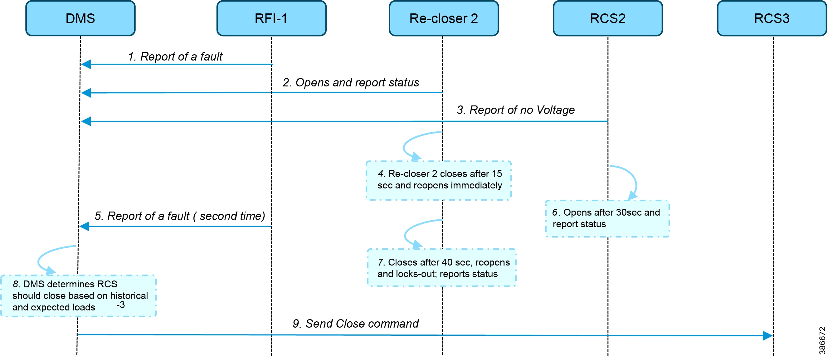
Use Case Steps
1.![]() Remote Fault Indicator (RFI) 1 reports to the DMS whenever it encounters a fault.
Remote Fault Indicator (RFI) 1 reports to the DMS whenever it encounters a fault.
2.![]() Re-closer 2 opens and sends a report to the DMS when it encounters a temporary fault.
Re-closer 2 opens and sends a report to the DMS when it encounters a temporary fault.
3.![]() Remote Control Switch (RCS) 2 reports no voltage status to the DMS.
Remote Control Switch (RCS) 2 reports no voltage status to the DMS.
4.![]() RCS 2 closes after 15 seconds and re-opens immediately.
RCS 2 closes after 15 seconds and re-opens immediately.
5.![]() RFI 1 reports fault for the second time.
RFI 1 reports fault for the second time.
6.![]() RCS 2 opens after 40 seconds and reports status.
RCS 2 opens after 40 seconds and reports status.
7.![]() Re-closer 2 closes after 40 seconds, reopens and locks out permanently, and report status to the DMS.
Re-closer 2 closes after 40 seconds, reopens and locks out permanently, and report status to the DMS.
8.![]() The DMS decides to issue a close command to RCS 3.
The DMS decides to issue a close command to RCS 3.
FLISR Use Case Simulation
1.![]() Load the FLISR workspace by importing into DTM. The FLISR workspace can be found in Appendix E: HER and CGR Configurations, page 196.
Load the FLISR workspace by importing into DTM. The FLISR workspace can be found in Appendix E: HER and CGR Configurations, page 196.
2.![]() Start all the host machines.
Start all the host machines.
Figure 254 DTM FLISR Start All Hosts
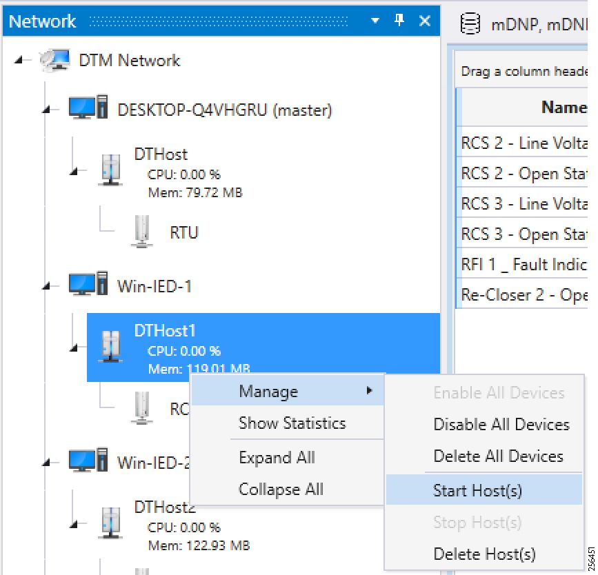
3.![]() Start the FLISR DTM Simulation script.
Start the FLISR DTM Simulation script.
Figure 255 DTM FLISR Start the Script
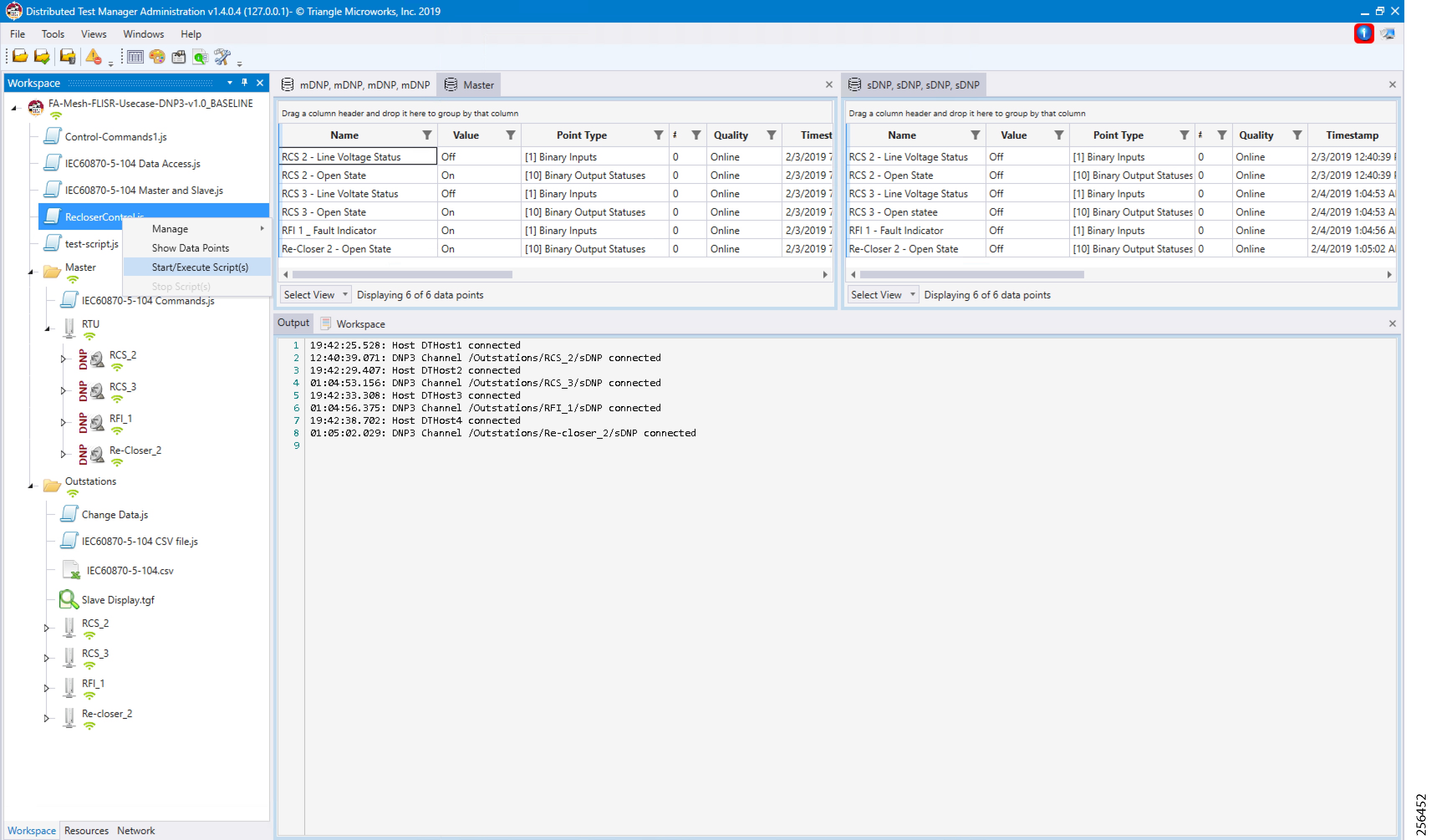
4.![]() Simulate the fault by changing the RFI1 data once. Click on Change Data Once on the RFI1 outstation device.
Simulate the fault by changing the RFI1 data once. Click on Change Data Once on the RFI1 outstation device.
Figure 256 DTM FLISR Execute the RFI Script Once
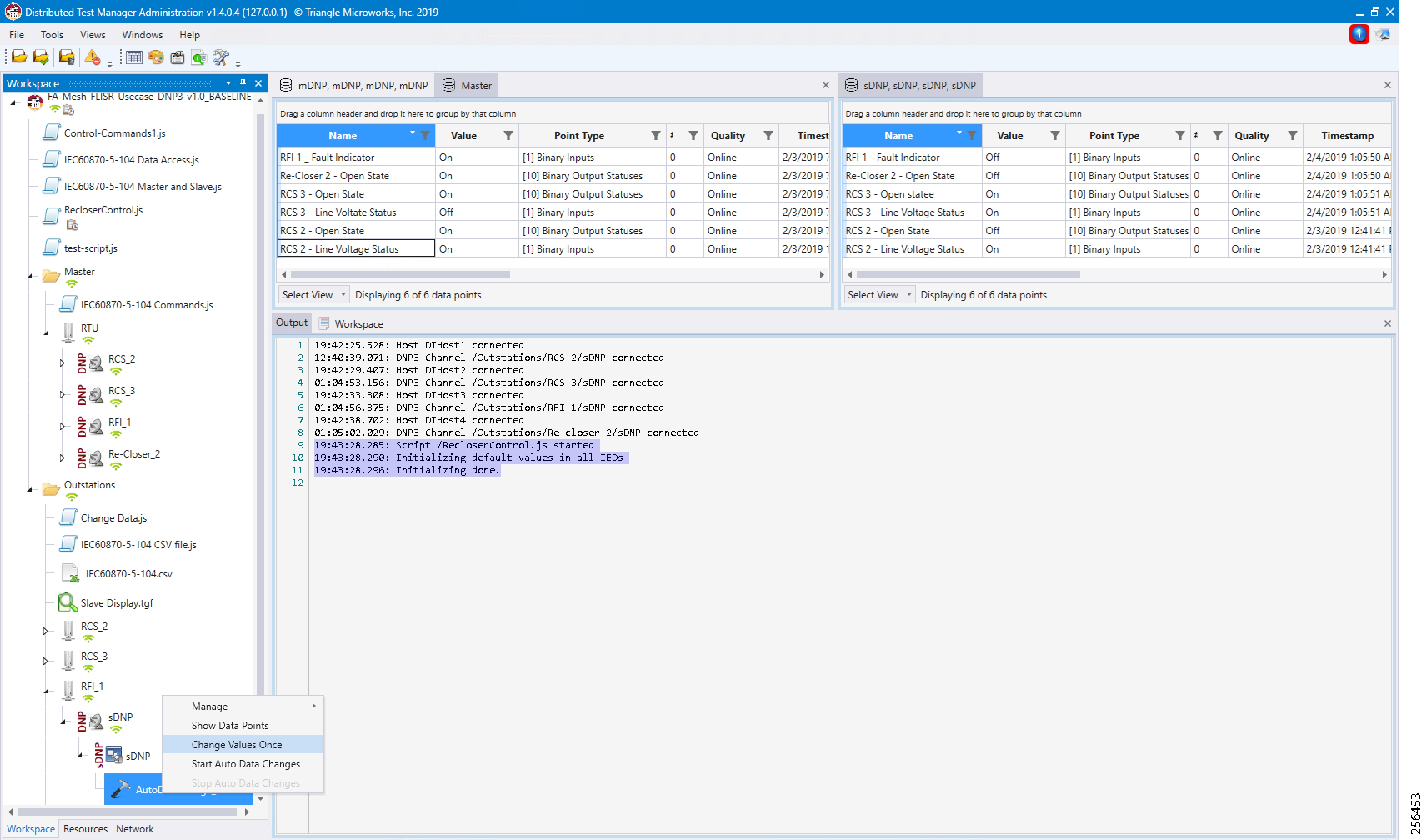
Note: The FLISR use case steps 1 to 9 are fully automated by the scripts.
Figure 257 DTM FLISR Simulation Completed
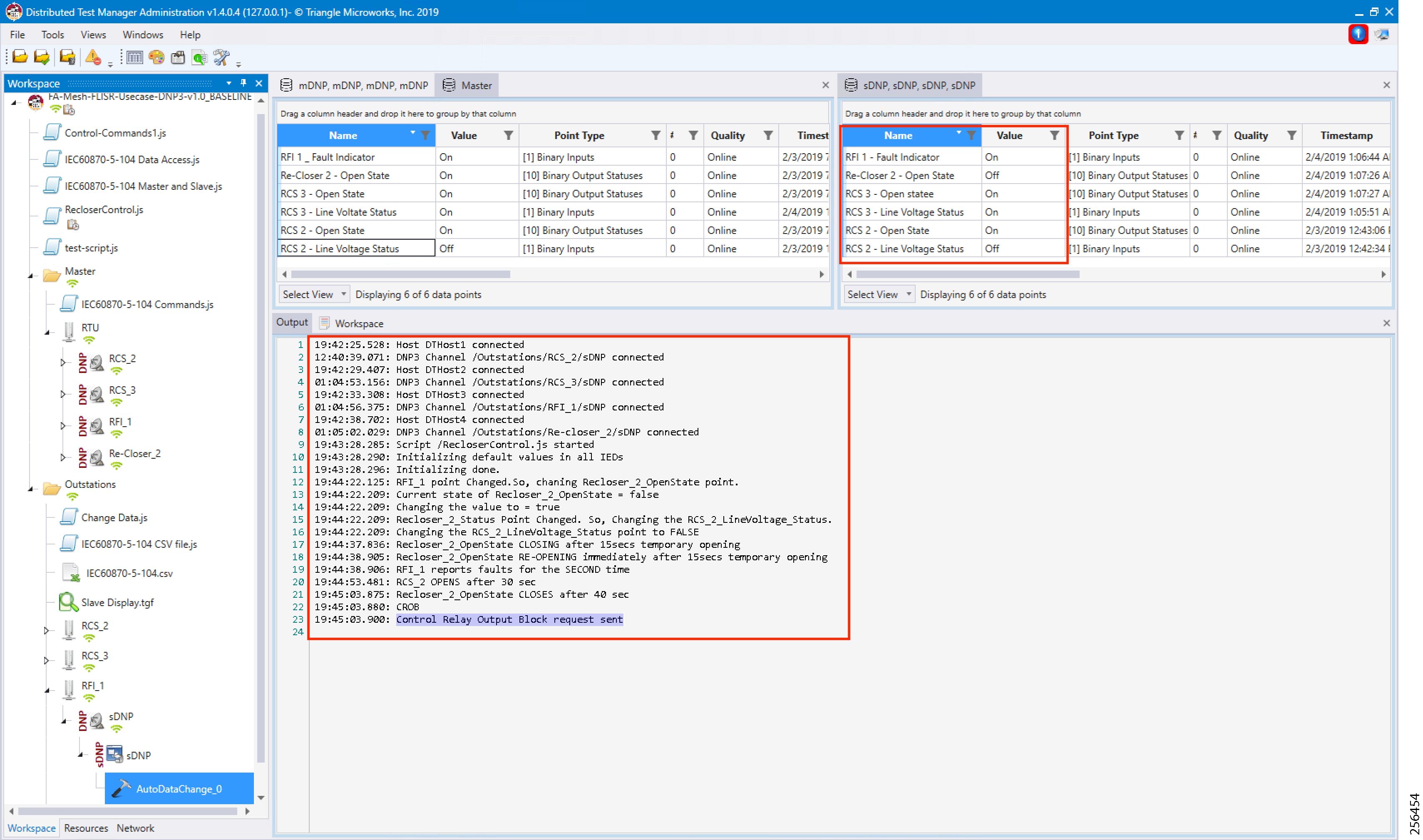
5.![]() Verify that the DTM logs are in line with the FLISR Event Sequence diagram of this document. Confirm the Control Command is sent from the control center to RCS3 in the last lines of the log. All Outstation data is updated to SCADA Control Center (Master) data points.
Verify that the DTM logs are in line with the FLISR Event Sequence diagram of this document. Confirm the Control Command is sent from the control center to RCS3 in the last lines of the log. All Outstation data is updated to SCADA Control Center (Master) data points.
 Feedback