Grid Security 3.1 Implementation Guide
Introduction
Smart Grid is an electricity delivery system that is integrated with communications and information technology to enhance grid operations, improve customer service, lower costs, and enable new environmental benefits. This document describes the overall use of the network to monitor and manage the electrical system from power generation, through transmission and distribution, to end users in smart buildings, smart homes, and other sites connected to the utilities network. As the OT world collides with the traditional IT world, security is becoming increasingly important for utilities customers. Today’s news includes many stories about hackers and terrorists that seek to gain access to critical networks in order to steal money, information, or even to disrupt service.
This solution seeks to address many of these concerns by providing a holistic approach to restricting access, protecting data, logging events and changes, and monitoring activity in the substation. The Substation Security solution addresses the NERC-CIPv5 CIP requirements. While only applicable in North America, much of the world is looking to NERC-CIP as the standard to secure their utility and other industrial operations.
The substation network must be protected from unauthorized access and cyberattacks. The substation network security services must guarantee the integrity of telemetry data and control commands to ensure confidentiality, integrity and availability of the electronic information communication system. These security services must be deployed at each networking protocol layer whenever it is applicable.
For more details please refer to Grid Security Design Guide that can be found at the following URL:
https://www.cisco.com/c/en/us/td/docs/solutions/Verticals/Distributed-Automation/Grid_Security/DG/DA-GS-DG.html
Navigator
This document includes the following:
|
|
|
|
|
|
|
|
|
|
|
|
|
|
|
|
|
|
|
|
|
|
|
|
|
|
|
|
|
|
|
|
|
This Cisco Grid Security Implementation Guide provides a comprehensive explanation of the network and application level security implementation for protecting the smart grid systems. Utilities are interested in gaining visibility of SCADA Operational Technology and Engineering traffic flows occurring within and across substations. This guide addresses how to use Smart Grid systems to get this visibility. This guide also captures implementation details of mandatory compliance requirements of the North American Electric Reliability Corporation Critical Infrastructure Protection (NERC CIP). The solution architecture, possible deployment models, and recommended guidelines for deployment are discussed.
Audience
The audience of this guide comprises system architects, network/compute/ systems engineers, field consultants, Cisco customer experience specialists, and customers. Readers may be familiar with networking protocols, security concepts of firewall, encryption, deep packet inspection, public key infrastructure and Cisco substation automation solution architecture.
Document Objective and Scope
This guide helps provide details of the Grid Security Solution implementation that is an addition to Cisco Substation Automation 2.3.2 CVD Architecture and Cisco Distribution Automation – Secondary Substation Architectures here:
https://www.cisco.com/c/en/us/td/docs/solutions/Verticals/Utilities/SA/2-3-2/CU-2-3-2-DIG.pdf
https://www.cisco.com/c/en/us/td/docs/solutions/Verticals/Distributed-Automation/Secondary-Substation/DG/DA-SS-DG.html
The scope addressed in this document is Cisco Information and Communication Technology (ICT) solution architecture and implementation for modern transmission substations and secondary substations, including the Cisco solution for process and station buses in substation LAN environment per IEC 61850 protocol standard. It describes how the fault-tolerant multi service network design is implemented, and how network segmentation is implemented across various substation application flows.
The methods by which utility actors like Human Machine Interface systems (HMI), Remote Terminal Unit (RTU), workforce PCs, laptops, IP cameras and phones get authenticated and authorized are discussed. How confidentiality and data integrity is implemented for various applications flows to and from substations is included. This document also explains how to achieve visibility of assets and Operational Technology (OT) application flows of the Smart Grid. How to perform threat detection and perform necessary remedies are also detailed.
Implementation Workflow
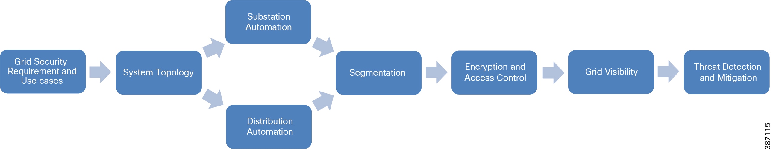
The user of this guide can pick the flow based on need, which can either be Grid Security implementation for Substation Automation deployments or Distribution Automation deployments. The following figure shows the flow of information in this implementation guide. The guide may also have cross references to other sections in this document or related guides to help the reader understand the bigger picture.
Figure 1 Grid Security Solution 3.1 Implementation Flow
Grid Security Requirements and Use cases
Security is an important success criterion for the modernization of the Electrical Grid and for all new developments. Most security requirements and regulatory compliances for Grid Security are well defined in NERC CIP and National Institute of Standards and Technology (NIST), and IEC 62351 specifications. NERC CIP requirements and the Cisco solution implementation to address the NERC CIP requirements are the focus of this guide.
NERC-CIP
The NERC-CIP serves as a reference for the US Department of Energy Cyber Security guidelines for electricity and oil and gas distribution. NERC-CIP is also an excellent reference model for other industries. This set of compliance standards are designed to improve reliability and protect Bulk Electrical Systems (BES) against “cybersecurity compromises that could lead to mis-operation or instability”.
These standards are not a definitive guide to security, but a framework designed to ensure that the right practices - not simply products or features - are in place to lessen the potential of disturbances. The NERC CIP standards focus on policy, process, and procedure while staying away from technical recommendations, with a few exceptions.
The Cisco integrated portfolio and information concerning cybersecurity for control networks, corporate networks, and physical security help you meet the challenging NERC CIP operational standards with minimal operator burden and capital expenditure.
NERC-CIP requirements can be broadly classified into five categories:
■![]() Critical Asset identification and categorization
Critical Asset identification and categorization
■![]() Segmentation to establish Electronically Secure Perimeter
Segmentation to establish Electronically Secure Perimeter
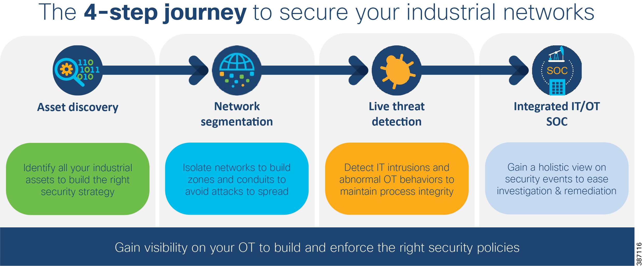
The NERC CIP standards are primarily focused on establishing policies, programs, and procedures. To help achieve compliance with the underlying technology, the following steps are recommended:
1.![]() Discover your assets and systems
Discover your assets and systems
2.![]() Establish physical and logical protection perimeters
Establish physical and logical protection perimeters
3.![]() Enforce controls at and within those perimeters to protect BES reliability and integrity
Enforce controls at and within those perimeters to protect BES reliability and integrity
4.![]() Gain a holistic view on security events to ease investigation and remediation.
Gain a holistic view on security events to ease investigation and remediation.
The NERC-CIP standards currently subject to enforcement are described in the following table.
The following requirements are the focus of this implementation guide:
■![]() CIP-002 which focuses on cyber system discovery and categorization
CIP-002 which focuses on cyber system discovery and categorization
■![]() CIP-005 which mandates the establishment electronic security perimeters to protect High- and Medium-Impact cyber systems
CIP-005 which mandates the establishment electronic security perimeters to protect High- and Medium-Impact cyber systems
■![]() CIP-007 which focuses on system access controls (role-based access control), security event monitoring, discovery of open ports and services, anomalies detection in real time to enforce policies and perform threat mitigation
CIP-007 which focuses on system access controls (role-based access control), security event monitoring, discovery of open ports and services, anomalies detection in real time to enforce policies and perform threat mitigation
Asset Discovery and Identification
The foundational building blocks of NERC CIP compliance is to discover your cyber systems to categorize as required in CIP-002-5. The ability to passively discover devices, protocols, users, communications patterns, and so on, is used to build a picture of “normal.” Understanding what is normal enables base-lining and highlighting anomalies. Where control networks are intended to be static, anomaly detection is dynamic and white-listing is valuable. A white-listing approach allows permitted traffic to proceed as normal, and anomalous traffic is inspected for malicious content. By understanding the context in which events occur and the potential impacts to your environment, we help you to prioritize your team’s efforts efficiently and effectively.
Lack of visibility is a problem in ICS environments. Many customers don’t have accurate Asset Inventory, and are therefore blind to asset communications. A key advantage of the Cisco Grid Security Solution is that CIP-002-5 is comprehensively examined to understand the difference between acceptable discovery techniques in a control environment contrasted with the techniques an IT environment. It is possible to passively discover devices, protocols, users, communications patterns, and so on, to build a picture of “normal.”
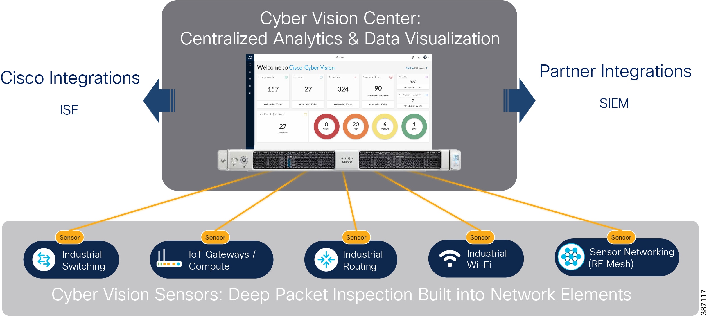
The Cisco Cyber Vision Center (CVC) and sensors can passively discover and categorize assets, protocols and topologies of your OT networks. The Cisco Cyber Vision solution is two-tier architecture in which sensors are installed in OT premises and the Cyber Vision Center for centralized analytics & data visualization resides in the control center. These two aspects are connected by a segmented inline collection network that carries communication between them. Sensors and the cyber vision center application of Cisco Cyber Vision can easily integrate with the Identity Service Engine (ISE), Firepower, for policy enforcement.
The Grid Security Implementation section address in details about Cisco Cyber Vision solution implementation.
After assets have been identified and categorized, creation of electronic security perimeters (ESPs) is implemented. This implementation is discussed below.
Segmentation and Access Control
CIP-005-5 requires that an ESP must be established for all high-impact and medium-impact Bulk Electrical System (BES) Cyber Systems that are connected to a network via a routable protocol, regardless of whether that segment containing the BES Cyber System(s) has external connectivity to any other network segment. There may be BES Cyber Systems of varying impact classifications within a single ESP; all BES Cyber Systems in the ESP require the highest level of protection corresponding to the BES Cyber System with the highest impact classification. All External Routable Connectivity (ERC) must be through an identified Electronic Access Point (EAP). This requires inbound and outbound access permissions, including the reason for granting access, and to deny all other access by default. Using one or more methods to detecting known or suspected malicious communications for both inbound and outbound communications is preferred.
An ESP can be defined by segmentation. Methods of segmentation include L2 VLANs, L3 VRFs, firewall interfaces and/or security contexts, and Security Group Tags (SGT) which can provide segmentation regardless of VLAN or IP address assignment. By creating logical zones within the substation, each with their own unique security requirements and using the capabilities of the Cisco ISA-3000 industrial firewall and the Cisco Identity Services Engine, a number of the key cybersecurity requirements can be met.
Access control is identification and authentication control in the utility environment, means to verify the identity of users (humans, software processes, devices) requesting access before activating communication. The aim is to prevent illegitimate (unauthenticated) access of selected devices or data. It is important to define what devices are connected to a network, at what location, and who is operating that device. Allow only known users. Limit number of devices connected to Substation Bus or Distribution Automation Gateways. Prevent rouge devices/users accessing the network. Control and limit access to the resources. Maintain logs of users OT transactions and events.
Threat Detection and mitigation
360° threat detection—Detect threats before it is too late. Abnormal traffic detection and mitigation post thread detection. Protect critical assets against cyber-attacks and insider threats. The anomaly detection is the process to determine which observed events are to be identified as abnormal because it has significant deviation from normal behavior which is called baseline.
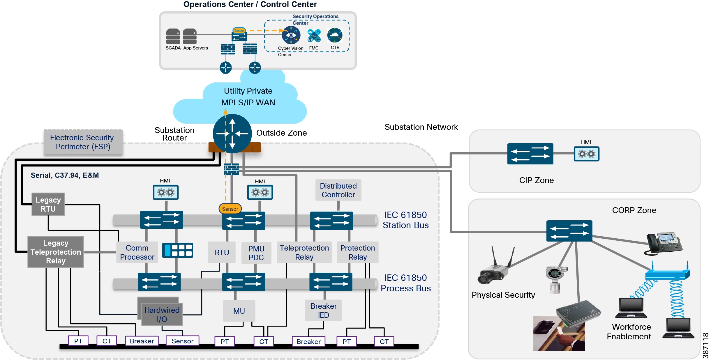
Substation design
Key components of a Substation design include:
■![]() a Corporate Substation (CORPSS) zone
a Corporate Substation (CORPSS) zone
■![]() a Critical infrastructure Perimeter (CIP) zone
a Critical infrastructure Perimeter (CIP) zone
■![]() the Electronic Security Perimeter (ESP) zone
the Electronic Security Perimeter (ESP) zone
Relative firewall security levels are provided to illustrate trust levels between zones.
Figure 4 Grid Security Architecture for Substation Automation
Network Resiliency
High availability for Information and Communication Topology network layer provides network resiliency and better convergence at times of network faults. Various protocols can be used. Some legacy resiliency protocols within ring topology deployments are:
■![]() Rapid Spanning Tree (RSTP) is a variant of spanning tree protocol (STP) that is known, used, and trusted by IT professionals who have used Cisco switches.
Rapid Spanning Tree (RSTP) is a variant of spanning tree protocol (STP) that is known, used, and trusted by IT professionals who have used Cisco switches.
■![]() Resilient Ethernet Protocol (REP) - a Cisco proprietary protocol described below.
Resilient Ethernet Protocol (REP) - a Cisco proprietary protocol described below.
IEC 61850 implementation standards in the station bus and process bus, high performance applications in the utility substation mandate a number of key requirements to be addressed. The substation architecture must meet design requirements for GOOSE and Sample Values, both of which are multicast traffic types. This includes high availability (HA) and topology choices to meet scale, segmentation, and communications requirements. IEC 61850-5 provides guidance for HA and communication requirements based on a number of use cases in the standards. With these failover and recovery times at ZERO milli-seconds for some use cases, a truly “hitless” architecture is required. There are two choices to meet this hitless requirement:
■![]() Parallel Redundancy protocol (PRP) supports either tree or ring topologies with no limits on node counts, and it can deliver a ZERO millisecond failover/recovery requirement. However, PRP has one drawback. PRP requires duplicate LANs (named LAN-A & LAN-B) and double the networking equipment hardware.
Parallel Redundancy protocol (PRP) supports either tree or ring topologies with no limits on node counts, and it can deliver a ZERO millisecond failover/recovery requirement. However, PRP has one drawback. PRP requires duplicate LANs (named LAN-A & LAN-B) and double the networking equipment hardware.
■![]() Highly Available Seamless Ring (HSR) also delivers a ZERO millisecond fail-over/recovery requirement but is only available in a ring topology and scales to a limited number of devices. HSR does NOT require duplicate LANs (double the switching infrastructure) in the ESP.
Highly Available Seamless Ring (HSR) also delivers a ZERO millisecond fail-over/recovery requirement but is only available in a ring topology and scales to a limited number of devices. HSR does NOT require duplicate LANs (double the switching infrastructure) in the ESP.
For more details on design recommendations and implementation of network resiliency refer to the following: https://www.cisco.com/c/en/us/td/docs/solutions/Verticals/Utilities/SA/2-3-2/CU-2-3-2-DIG.pdf
Electronic Security Perimeter (ESP) zone
The ESP zone contains components that play an active role in the proper functionality of the Critical Infrastructure/Smart Grid. These components should be regarded as being the most valued and trusted resources on the Substation network and highly protected.
With very few exceptions, outbound communications from this portion of the network must be significantly restricted. Any communication from this zone to any lower-security zone should leverage a “Pull” model – initiating the connection from the ESP zone. Inbound connections into the ESP zone should be discouraged except for any business-critical applications.
This zone is intended to provide limited network connectivity for industrial components such as IEDs and Protection Relays with direct user-level access restricted to appropriately-vetted employees that require direct Substation access for machine maintenance. Depending on the security model employed, access to the IEDs and Protection Relays can also be restricted to specific, well vetted, and highly audited hosts, denying access from personal/corporate laptops. Outbound connections are highly restricted from this zone.
Corporate Substation (CORPSS) zone
The Corporate Substation zone is a natural extension to the corporate/enterprise “General Purpose” network. Traffic from this zone can only access other corporate assets directly by passing through the Outside zone. Access to the other zones (CIP and ESP) requires additional credentials and access restrictions.
All employees can leverage this zone for basic connectivity to business resources including email, file shares, and general access to the Internet via the Outside zone
Critical Infrastructure Perimeter (CIP) zone
The CIP zone is a “DMZ” for the Substation. This zone is “semi-trusted” an has a Firewall security level between the Corporate Substation zone and the ESP zone. As such, this zone is designed to allow proxied user-level access between both the Corporate Substation and ESP zones — leveraging an information security (InfoSec) hardened Bastion host. Other support infrastructure may also exist in this zone such as a Secure Policy Server such as Cisco ISE or ACS, Network Services, and/or a user management server such as Lightweight Directory Access Protocol (LDAP) or Active Directory (AD).
Inbound connectivity into this zone is provided via a Remote Access VPN client or via a Courtesy port within the CIP zone switch network. The Courtesy Port will be discussed in detail in a later section of this document. As a user connects into the CIP zone, the user’s level of access will be restricted to allow connectivity to ONLY the Bastion host. This Bastion host will have predefined levels of access inbound into the ESP zone and outbound towards the corporate network. All user-level connectivity between the ESP and Corporate Substation networks will be proxied via this Bastion host. Access to and from other resources within the CIP zone must also be significantly restricted to ensure the integrity of these resources and their interactions with the ESP zone.
Traffic can flow from any employee or contractor that has the proper credentials to operate the network and security resources within this zone. Membership in the appropriate Active Directory (AD) group can be leveraged to restrict Courtesy Port or Remote Access authentication and authorization accordingly.
Outside zone
This zone connects the Substation topology to the rest of the infrastructure, whether the infrastructure is owned by the Utility Corporation or provided by a 3rd party Service Provider. This zone is untrusted. The security postures of assets within this outside zone are, in most cases, outside of the control of the Utility Corporation.
The traffic allowed to traverse this interface should be encrypted, authenticated, and/or originally initiated from the inside zones (ESP, CIP, and CORPSS) of the ISA3000 firewall. The AnyConnect Remote Access endpoints can authenticate to the Outside interface to gain access to the CIP and ESP zones.
Because this zone is considered outside the Substation architecture, the protection of this zone is varied and relies solely on the protections provided by the WAN infrastructure.
In an actual Connected Utilities “Smart Grid” architecture, the Substation block may be repeated multiple times across the network architecture. Certain components of the Substation design may also be optional depending on the size, the function, and the topology of the substation.
Traffic segmentation within the Substation
Within substations the following VLANs are suggested to protect mission critical traffic from potential network attacks:
■![]() OT SCADA VLAN - This VLAN is for SCADA traffic such as Modbus, DNP3, IEC61850 GOOSE. We are starting to see the Process bus and station bus become segmented based on common communication peers for security and operation performance benefits.
OT SCADA VLAN - This VLAN is for SCADA traffic such as Modbus, DNP3, IEC61850 GOOSE. We are starting to see the Process bus and station bus become segmented based on common communication peers for security and operation performance benefits.
■![]() Network Management VLAN - For all network management traffic. A designated management port is enabled within a VLAN that is used by the management system to communicate with the devices.
Network Management VLAN - For all network management traffic. A designated management port is enabled within a VLAN that is used by the management system to communicate with the devices.
■![]() Remote Workforce VLAN (Intranet) - The remote workforce accesses the substation network using on-site ruggedized PC or wire connected PC.
Remote Workforce VLAN (Intranet) - The remote workforce accesses the substation network using on-site ruggedized PC or wire connected PC.
■![]() Remote Workforce VLAN (Internet) - Partner or third-party crew is allowed on this VLAN to gain access to the Internet. Only outbound traffic is permitted.
Remote Workforce VLAN (Internet) - Partner or third-party crew is allowed on this VLAN to gain access to the Internet. Only outbound traffic is permitted.
■![]() Physical Security VLAN - Video surveillance traffic, physical access traffic.
Physical Security VLAN - Video surveillance traffic, physical access traffic.
■![]() Black Hole VLAN - As a security best practice, all unused ports are assigned to this VLAN.
Black Hole VLAN - As a security best practice, all unused ports are assigned to this VLAN.
VRF Segmentation at the substation router should follow VLAN segmentation.
Access Control
Ensure that only authorized personnel are accessing the network and valid devices are part of the grid network by using the suggestions below.
■![]() Authenticating and authorizing field technicians or operations center staff before they can view or configure devices, track changes made - role-based access control (RBAC). For engineer/technician devices that need to access the substation, only 802.1x authenticated users should be permitted access.
Authenticating and authorizing field technicians or operations center staff before they can view or configure devices, track changes made - role-based access control (RBAC). For engineer/technician devices that need to access the substation, only 802.1x authenticated users should be permitted access.
■![]() Authenticating users and endpoints connected to the substation / control center networks, via various different methods such as AAA and/or endpoint certificates. MAC Authentication Bypass (MAB) is used for endpoints do not have 802.1x supplicant.
Authenticating users and endpoints connected to the substation / control center networks, via various different methods such as AAA and/or endpoint certificates. MAC Authentication Bypass (MAB) is used for endpoints do not have 802.1x supplicant.
■![]() Limit the number of devices that can be connected to the port. Prevent rogue/unknown devices connected to the network.
Limit the number of devices that can be connected to the port. Prevent rogue/unknown devices connected to the network.
■![]() To protect LAN switches from being exploited, unused ports of all LAN switches at the substation must be shut down by default. All ports must be explicitly enabled. For those ports that are enabled, configure port security to protect the network from LAN-based attacks. This feature limits the number of MAC addresses that are able to connect to a switch, and ensures that only approved MAC addresses are able to access the switch.
To protect LAN switches from being exploited, unused ports of all LAN switches at the substation must be shut down by default. All ports must be explicitly enabled. For those ports that are enabled, configure port security to protect the network from LAN-based attacks. This feature limits the number of MAC addresses that are able to connect to a switch, and ensures that only approved MAC addresses are able to access the switch.
■![]() Port Security prevents MAC address flooding and ensures that only approved users can log onto the network. The following security policy applies to port security configuration:
Port Security prevents MAC address flooding and ensures that only approved users can log onto the network. The following security policy applies to port security configuration:
–![]() The maximum number of secure MAC addresses for a port is one.
The maximum number of secure MAC addresses for a port is one.
–![]() Specify static MAC addresses for IED or other IP-enabled control devices.
Specify static MAC addresses for IED or other IP-enabled control devices.
–![]() If the IED MAC is unknown in certain deployment scenarios, use sticky port security.
If the IED MAC is unknown in certain deployment scenarios, use sticky port security.
Bandwidth Control
Prevent a malicious user taking up the bandwidth and thereby starve critical application traffic. Prevent data traffic from the contractor occupying the network and affecting the control traffic. Rate limiters can limit traffic per VLAN, port or user to mitigate the impact of packet-blasting worms and limit amount of traffic a user can send onto the network. Operators can rate limit using either traffic policing or shaping functions.
Threat Detection
NERC/CIP 007 defines requirements for Threat detection. Baseline the OT Traffic for anomaly detection. Deep packet inspection of OT Traffic for attack detection and prevention.
Security Event Monitoring, Malicious Code Prevention, and Patch Management
For Anomaly detection discover the open ports and services for various OT flows in substation. This can be done with Cyber Vision Center and Cyber Vision Sensors as discussed in the implementation section. Enforce control policies from Identity Service Engine on the policy server to different network devices like firewall and network switches if a change in the baseline is detected.
SCADA/OT preprocessor features can be enabled on substation firewall for zero day attack detection of OT traffic. This preprocessor can be perform deep pack inspection of SCADA packet headers and OT commands. For more details on OT preprocessor refer to:
https://www.cisco.com/c/en/us/td/docs/security/firepower/630/configuration/guide/fpmc-config-guide-v63/scada_preprocessors.html
IPS with built-in signatures for malicious code prevention and end point posture assessment of for devices as laptops, workstations, servers connecting to Substation/CC LAN segments to detect any virus/spyware before allowing access to the network, forcing remediation such as installing software patches or updating anti-virus database.
Distribution Automation design
Distribution Automation (DA) refers to the monitoring and control of devices located on the distribution feeders, such as line reclosers, load break switches, sectionalizers, capacitor banks and line regulators and also devices located in the distribution substation. DA is an overlay network deployed in parallel to the distribution feeder. It enables two-way communication between controllers used in the distribution feeder and the intelligence application that resides in the Utility Control Center or Secondary Substation for improving grid reliability, availability, and control. This guide focuses on Secondary Substation Distribution Automation use case using IR1101 as Cellular Gateway.
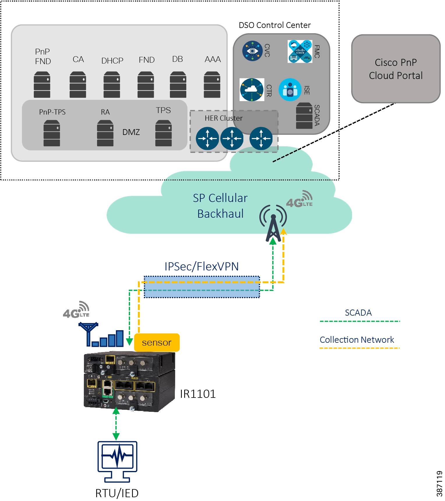
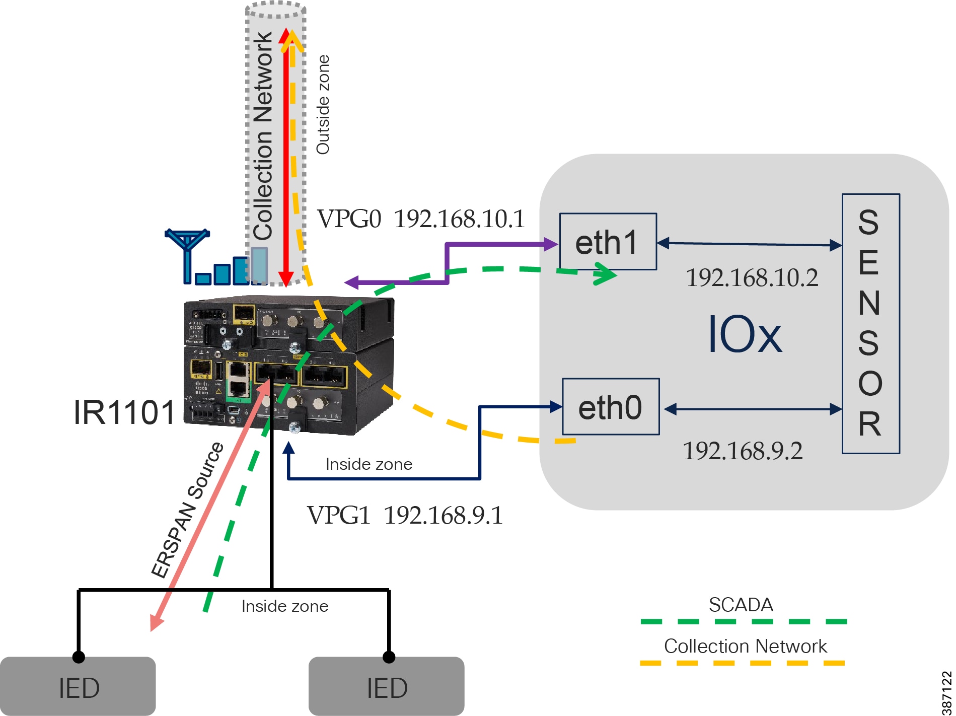
DA Secondary Substation Architecture is a two-tier centralized Architecture. WAN tier i.e. cellular backhaul connects Distribution Substation/Grid to the Centralized Control Center. Cisco IR1101 can be positioned as Secondary Substation Router (SSR) to connect to various OT devices like RTU, IED, Meter Data concentrators, Capacitor Bank controllers and Voltage Regulator controller. The following figure illustrates a simplified topology.
DA use cases application flow can be classified as follows. Flow can be bidirectional.
Grid Security Solution Architecture implementation in this guide provides considerations for SCADA to IED application flows. It also considers the following as some of the security requirements for Distribution Automation Solution.
–![]() Authentication, Authorization & Accounting
Authentication, Authorization & Accounting
■![]() Data Confidentiality and Data Privacy
Data Confidentiality and Data Privacy
–![]() Security Connectivity and Encryption (VPN)
Security Connectivity and Encryption (VPN)
■![]() Threat Detection and Mitigation
Threat Detection and Mitigation
–![]() Intrusion Prevention with SCADA signatures
Intrusion Prevention with SCADA signatures
■![]() Device and Platform Integrity
Device and Platform Integrity
Figure 5 Grid Security Architecture for Secondary Substation Automation
For more details of other use cases and flows related to Distribution Automation Solutions, refer to the Distribution Automation Design and Implementation Guides:
https://www.cisco.com/c/en/us/td/docs/solutions/Verticals/Distributed-Automation/Secondary-Substation/DG/DA-SS-DG.html
https://www.cisco.com/c/dam/en/us/td/docs/solutions/Verticals/Distributed-Automation/Secondary-Substation/IG/DA-SS-IG.pdf
Network Resiliency in Distribution Automation
High availability is achieved by designing redundancy at multiple levels in the Distribution Automation solution as listed below:
■![]() Control center level - dual control center and application level redundancy, explained in SCADA Services.
Control center level - dual control center and application level redundancy, explained in SCADA Services.
It is beyond the scope of this implementation guide to explain various mechanisms. Refer to the following guide for details.
https://www.cisco.com/c/en/us/td/docs/solutions/Verticals/Distributed-Automation/Secondary-Substation/DG/DA-SS-DG/DA-SS-DG-doc.html#12933
System Overview
This section explains the topologies used for solution validation and the requirements for different components with features like licenses, IP addressing, and so on.
Topology
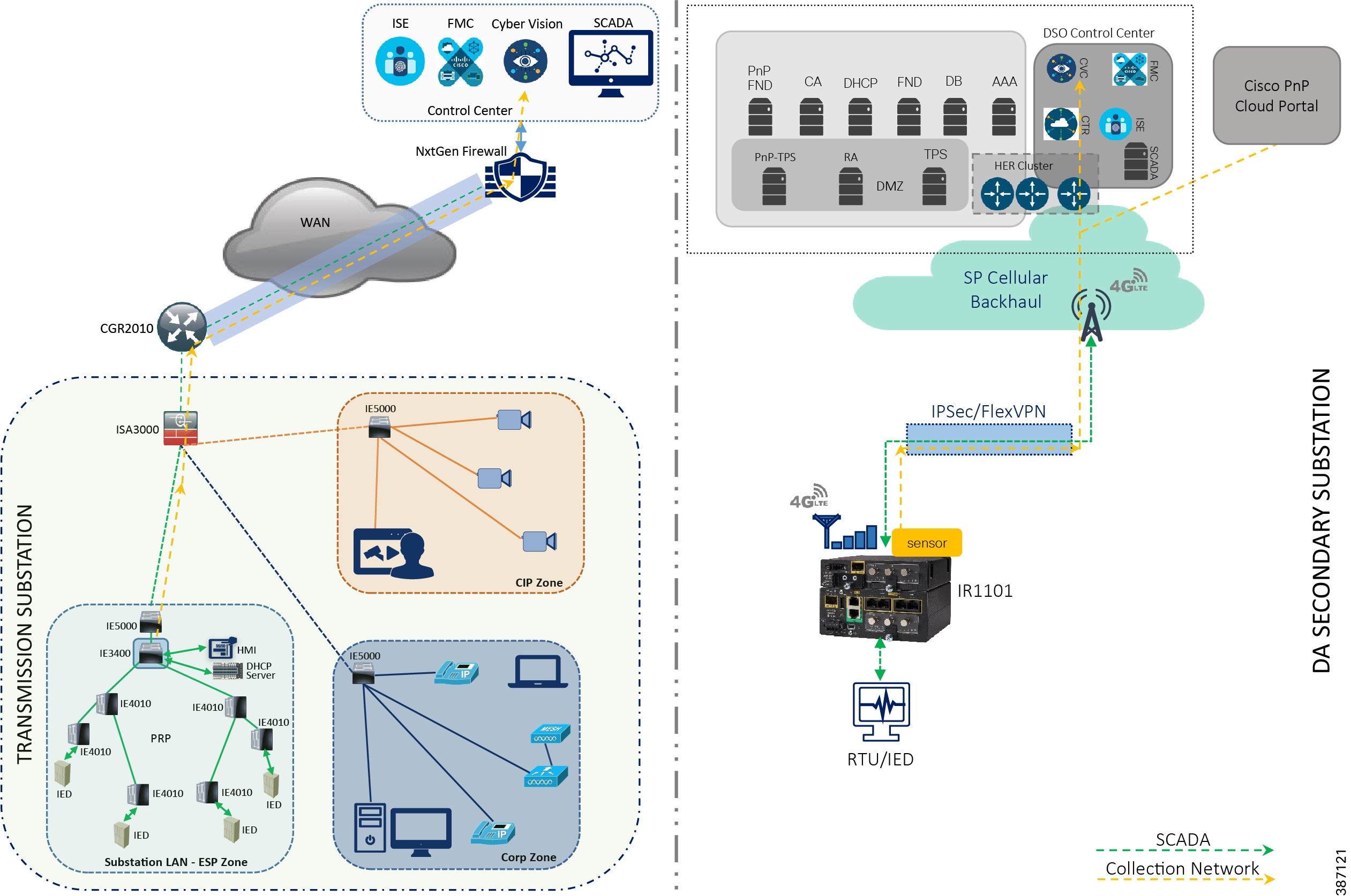
Cisco Substation Automation is a three-tier architecture including Substation LAN, Substation WAN, and Substation Control Center. The following figure illustrates a simplified Substation Automation topology. Cisco Distribution Automation Secondary Substation Architecture is a two-tier centralized Architecture. WAN tier i.e. cellular backhaul connects Distribution Substation/Grid to the Centralized Control Center. Cisco IR1101 can be positioned as Secondary Substation Router (SSR) or Distribution Automation (DA) Gateway for Feeder use cases. SSR and DA Gateways in turn connect to various OT devices like RTU, IED, Meter Data concentrators, Capacitor Bank controllers and Voltage Regulator controller. Figure 5 illustrates a simplified topology with IR1101 acting as Secondary Substation Router.
These architectures are represented in the following figure.
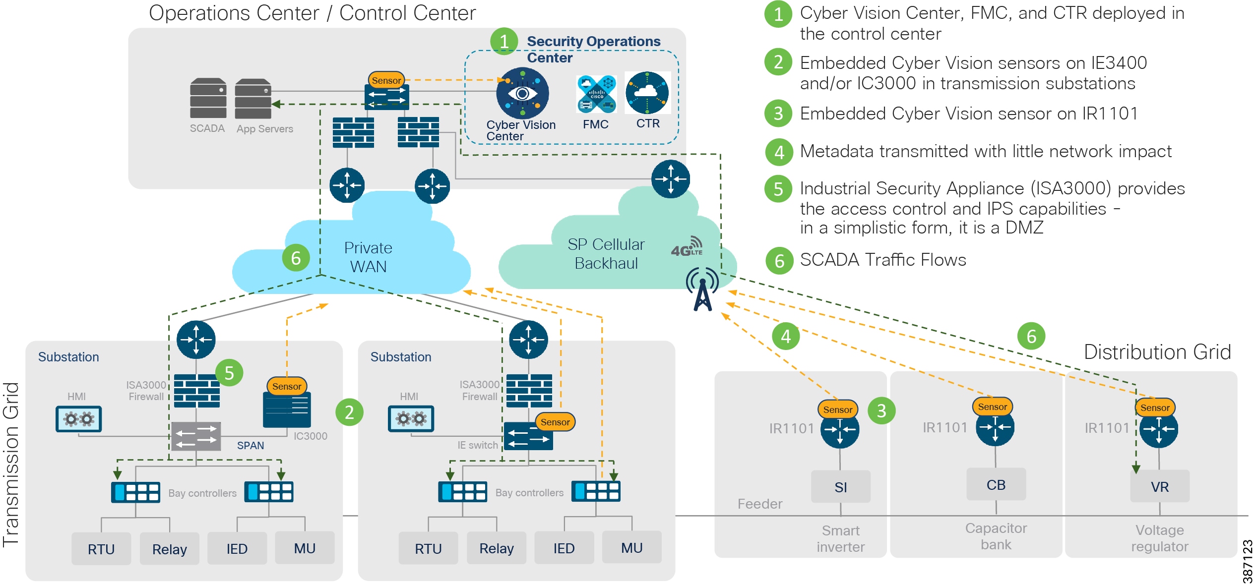
Figure 6 Grid Security Solution Logical Topology

To validate the designs and considerations, the solution testbed has been built in the lab as shown in the following figure. The focus of solution validation is on the components including the ISA3000, IC3000 as hardware sensor, IE3400 and IR1101 as network sensors, IE4000, IE5000, IE4010 switches. The control and data center applications that support them including Cisco Identity Services Engine, Cisco Cyber Vision Center and Firewall Management Center are also included. In this release of the solution, validation included configuring all components to work together to enable the desired use cases. Additional testing, including scale and performance, will be performed in a future release.
Figure 7 Grid Security Solution Validation Topology
IP Addressing/VLAN
This implementation assumes a simple topology for lab validation efforts. The following table lists the various IP Addresses and VLANs used for various components of the topology installed on a Cisco UCS server. ASR1K-Virtual acts as both NTP server and gateway to other components. Networks are defined for the virtual instances of different components for the reachability required. The following list includes networks defined in the UCS.
■![]() VM_Network - Uses IP addresses in the lab subnet for access to the Internet. Traffic is untagged.
VM_Network - Uses IP addresses in the lab subnet for access to the Internet. Traffic is untagged.
■![]() VM_Internal_Communication - Uses IP addresses in subnet 192.168.3.x for internal communication between various VMs. Traffic is untagged.
VM_Internal_Communication - Uses IP addresses in subnet 192.168.3.x for internal communication between various VMs. Traffic is untagged.
■![]() ISE_VLAN - Uses IP addresses in subnet 192.168.2.x for communication to Next Generation Firewall (NGFW). Traffic is tagged with VLAN 2.
ISE_VLAN - Uses IP addresses in subnet 192.168.2.x for communication to Next Generation Firewall (NGFW). Traffic is tagged with VLAN 2.
■![]() Collection_Network - Uses IP addresses in subnet 192.168.169.x for communication between Cyber Vision Center and Cyber Vision Sensors. Traffic is encrypted on IPSec tunnel when flowing over WAN or Internet. Traffic is tagged with VLAN 169.
Collection_Network - Uses IP addresses in subnet 192.168.169.x for communication between Cyber Vision Center and Cyber Vision Sensors. Traffic is encrypted on IPSec tunnel when flowing over WAN or Internet. Traffic is tagged with VLAN 169.
Hardware Software Matrix
The table below describes the hardware, software, and role of the main components of the solution. These software versions were used in the Cisco solution validation lab, and all were publicly available when this document was published.
Table 3 Hardware and Software Matrix
Licensing
The following table describes the hardware, software, and the corresponding licenses required to enable features and functions relevant to the solution. These licenses were the ones certified in Cisco’s solution validation lab, and all were publicly available at the time this document was published.
Table 4 Licenses and components
Grid Security Implementation
Security is an important success criterion for the modernization of the Electrical Grid as well as for all new developments. Most of security requirements and regulatory compliance for Grid Security are well defined in NERC CIP and National Institute of Standards and Technology (NIST). The recommended features and steps for implementation are discussed in the sections that follow.
Segmentation
Dividing a larger computer network into several small subnetworks that are each isolated from one another is called as Network Segmentation. It works by controlling the way traffic flows among the different parts of the network. It could help to stop all traffic in one part from reaching another, or can limit the flow by traffic type, source, destination, and many other options. VLANs, Access-Lists and Zones are some of the features to achieve network segmentation.
Some of the benefits of network segmentation are:
■![]() Improve operational performance.
Improve operational performance.
The following section lists the means to achieve segmentation for Grid Security Solution requirements.
Segmentation in Substation Automation LAN
As explained in the substation automation network design sections, VLANs and Firewall Zones are used for segmentation inside a substation LAN network. The following section lists the steps involved in provisioning the same.
VLAN for segmentation in switches
Network segmentation with virtual local area networks (VLANs) creates a collection of isolated networks within the Utility Network like Substation LAN. Each network is a separate broadcast domain. With proper planning, when configured, VLAN segmentation helps to restrict access to system attack surface. It reduces packet-sniffing capabilities and increases threat agent effort. Finally, authorized users only “see” the servers and other devices necessary to perform their daily tasks.
Another advantage of segmentation is protocol or device separation. Network architects can limit certain protocols or devices to certain segments of the network. For example, if IEC61850 GOOSE MMS or Sample Values exist on the network, they can each have their own VLAN in which to operate. This provides better management of data traffic and segments network traffic with similar network security requirements, yielding better resiliency during high-traffic communications, even during a cyberattack.
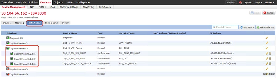
In this example, the Gigabit Ethernet1/2 interface on ISA3000 is configured with different VLANs so as to reach various devices in ESP zone. The ESP zone is further divided into multiple VLANs namely IES management for management of Industrial Ethernet Switches in ESP zone, IED for Utility devices in ESP Zone and IC3000 for IC3000 acting as Cisco Cyber Vision hardware sensors in ESP Zone. The switches in the ESP zone are also configured to allow these VLANs.
The following are the steps required to configure VLANs and corresponding sub interfaces on ISA3000 and Cisco Industrial Ethernet switches in Substation LAN network.
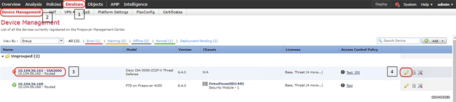
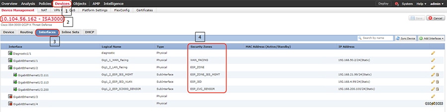
1.![]() Identify and select the ISA3000 device in Firepower Management Center that needs to be configured for different VLANs as explained above. The required steps are highlighted in the following figure:
Identify and select the ISA3000 device in Firepower Management Center that needs to be configured for different VLANs as explained above. The required steps are highlighted in the following figure:
Figure 8 Selection of ISA3000 in FM
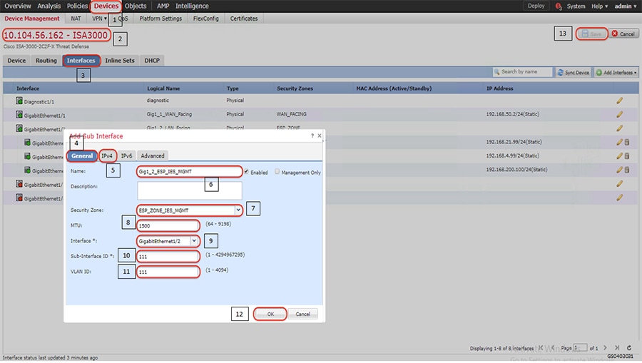
2.![]() Configure the device interface for the required sub-interface, corresponding IP address and save as highlighted in the following figure.
Configure the device interface for the required sub-interface, corresponding IP address and save as highlighted in the following figure.
Figure 9 Configuring ISA3000 sub interface using FMC
3.![]() Repeat step 2 to configure remaining VLANs as required.
Repeat step 2 to configure remaining VLANs as required.
4.![]() Use the following commands to configure VLANs on Industrial Ethernet Switches (IES).Repeat the step as required across the switches.
Use the following commands to configure VLANs on Industrial Ethernet Switches (IES).Repeat the step as required across the switches.
Verification
After the interfaces are configured and saved and connected, the status of the interface on the Graphical User Interface would turn green as highlighted in the following figure.
Figure 10 Configured ISA3000 sub interfaces
Similarly, a successful creation of VLAN on Cisco Industrial Ethernet switch would ensure that the VLANs are part of the allowed list on the respective interfaces. The following is a sample output to check successful creation of the VLAN.
Zones for segmentation in Firewall
There are four key components of a Substation design as explained in earlier section of this document – a Corporate Substation (CORPSS) zone, a Critical infrastructure Perimeter (CIP) zone, the Electronic Security Perimeter (ESP) zone, and the Outside zone.
■![]() ESP - this is the most secure zone containing critical components such as RTUs and IEDs. Access to the ESP zone is highly restricted. In the topology diagram, these are the components connected with ORANGE lines in the substation. This zone may contain multiple VLANs. This guide uses VLAN 111 for Industrial Ethernet Switch management, VLAN 113 for IEDs, VLAN 200 for Cisco Cyber Vision Hardware sensor.
ESP - this is the most secure zone containing critical components such as RTUs and IEDs. Access to the ESP zone is highly restricted. In the topology diagram, these are the components connected with ORANGE lines in the substation. This zone may contain multiple VLANs. This guide uses VLAN 111 for Industrial Ethernet Switch management, VLAN 113 for IEDs, VLAN 200 for Cisco Cyber Vision Hardware sensor.
■![]() Multiservice/CIP - this acts as kind of a demilitarized zone (DMZ) for the substation. This can contain the jump server host which has access to the ESP. Other items like video surveillance cameras, and local logging/ authentication, authorization, and accounting (AAA) applications reside here. This zone may contain multiple VLANs on the same IE4000 switch.
Multiservice/CIP - this acts as kind of a demilitarized zone (DMZ) for the substation. This can contain the jump server host which has access to the ESP. Other items like video surveillance cameras, and local logging/ authentication, authorization, and accounting (AAA) applications reside here. This zone may contain multiple VLANs on the same IE4000 switch.
■![]() CorpSS - this is an extension of the corporate network in the substation. It provides Wi-Fi connectivity, voice service, and general connectivity for employees to access email, web, or possibly the Internet through the central site.
CorpSS - this is an extension of the corporate network in the substation. It provides Wi-Fi connectivity, voice service, and general connectivity for employees to access email, web, or possibly the Internet through the central site.
■![]() Outside Zone/WAN – This zone connects the Substation topology to the rest of the infrastructure - whether the infrastructure is owned by the Utility/Corporation or provided by a 3rd party Service Provider. The traffic that should be allowed to traverse this interface should be encrypted, authenticated, and/or originally initiated from the inside zones (ESP, CIP, and CORPSS) of the ISA3000 firewall.
Outside Zone/WAN – This zone connects the Substation topology to the rest of the infrastructure - whether the infrastructure is owned by the Utility/Corporation or provided by a 3rd party Service Provider. The traffic that should be allowed to traverse this interface should be encrypted, authenticated, and/or originally initiated from the inside zones (ESP, CIP, and CORPSS) of the ISA3000 firewall.
Follow the steps listed in VLANs for Segmentation in switches section to configure zones.
Figure 11 Configured ISA3000 sub interfaces
Segmentation in Distribution Automation - Secondary Substation Gateway
As explained in the distribution automation network design sections, VRFs and Firewall Zones are used for segmentation inside a Distribution automation network. The following section lists the steps involved in provisioning the firewall zones. Segmentation using VRFs will be addressed in future guides.
Zone based Firewall
All traffic originating or passing through from the SSRs and DA Gateways can be protected by enabling IOS zone-based firewall. Zone Based Firewall (ZBFW) IOS feature can be enabled to detect and block unwanted flows. The ZBFW mainly deals with the security zones, where we can assign the router interfaces to various security zones and control the traffic between the zones, also the traffic will be dynamically inspected as it passes through the zones. Zone based firewall will support Application inspection and control for HTTP, POP3, Sun RPC, IM Applications and P2P File sharing. WAN facing interface like Cellular or FlexVPN tunnel is placed in outside zone and interfaces connected to DA IEDs and Edge Compute Application (internal logical interface) are placed on inside zone. Interzone communication is denied, traffic will be denied among the interfaces that are in the different zones unless we specify a firewall policy. The following topology depicts the same.
Figure 12 Distribution Automation Zone based firewall and segmentation
The following firewall policy is defined between outside and inside zones.
■![]() Allow following IPSEC FlexVPN ports
Allow following IPSEC FlexVPN ports
–![]() ISAKMP NAT-Traversal - UDP 4500 (NAT-T)
ISAKMP NAT-Traversal - UDP 4500 (NAT-T)
■![]() In Grid Security Design SCADA traffic is interesting traffic will be encrypted by IPSEC FlexVPN. So, there is no requirement to open up SCADA protocol ports. If needed following SCADA ports can be opened. Modbus Port 502, DNP3 port 20000, IEC 60870-5-104 port 2404 and IEC 61850 MMS port 102.
In Grid Security Design SCADA traffic is interesting traffic will be encrypted by IPSEC FlexVPN. So, there is no requirement to open up SCADA protocol ports. If needed following SCADA ports can be opened. Modbus Port 502, DNP3 port 20000, IEC 60870-5-104 port 2404 and IEC 61850 MMS port 102.
■![]() Open up ports number required for management application like FND, Cyber Vision Center and any other needed applications.
Open up ports number required for management application like FND, Cyber Vision Center and any other needed applications.
Intra-zone communication is allowed, traffic will flow implicitly among the interfaces that are in the same zone.
The following steps are required to configure zone-based firewall on secondary substation router.
1.![]() Before you create zones, you should group interfaces that are similar when they are viewed from a security perspective. By default, the traffic between interfaces in the same zone is not subject to any policy and passes freely. Firewall zones are used for security features.
Before you create zones, you should group interfaces that are similar when they are viewed from a security perspective. By default, the traffic between interfaces in the same zone is not subject to any policy and passes freely. Firewall zones are used for security features.
2.![]() Configure Layer 3 and Layer 4 firewall policies.
Configure Layer 3 and Layer 4 firewall policies.
3.![]() Create security zones and zone pairs.
Create security zones and zone pairs.
4.![]() Assign the interfaces to the respective zones. In this example FlexVPN tunnel is the OUTSIDE interface.Collection network interface VirtualPortGroup1 and a VLAN1000 are INSIDE interfaces.
Assign the interfaces to the respective zones. In this example FlexVPN tunnel is the OUTSIDE interface.Collection network interface VirtualPortGroup1 and a VLAN1000 are INSIDE interfaces.
5.![]() The functioning of the feature can be verified using the following command.
The functioning of the feature can be verified using the following command.
IP Network Encryption
Site to Site VPN in Substation LAN
Based on NERC-CIP, the various zones in a Substation LAN as defined in the earlier section needs to communicate over an encrypted VPN tunnel to the centralized data center. IKEv2 is used to provide secure authentication and negotiation of the encryption and integrity methods to form the security association (SA). Cisco IP Security (IPsec) is used to provide encryption and integrity for payload data. However, traffic inside the Substation LAN network is not encrypted.
This section lists the basic steps to establish a simple IPSec tunnel between Cisco CGR2010 and Cisco FPR4150 devices using Firepower Management Console (FMC).
■![]() Cisco FPR4150 acts as Firepower Threat Defense (FTD) device.
Cisco FPR4150 acts as Firepower Threat Defense (FTD) device.
■![]() Cisco FPR4150 device runs FTD version 6.4.0.
Cisco FPR4150 device runs FTD version 6.4.0.
■![]() Cisco CGR2010 and Cisco FPR4150 devices required respective licenses to support strong encryption algorithms. Refer to data sheets and ensure the corresponding licenses are activated.
Cisco CGR2010 and Cisco FPR4150 devices required respective licenses to support strong encryption algorithms. Refer to data sheets and ensure the corresponding licenses are activated.
This section assumes that FTD devices are managed by FMC.
Upgrading FTD devices, setting up FMC and integrating FTD devices with FMC are out of scope for this guide. Refer the corresponding configuration guides.
Note: For details to setup FMC refer the following guide: https://www.cisco.com/c/en/us/td/docs/security/firepower/640/configuration/guide/fpmc-config-guide-v64.html
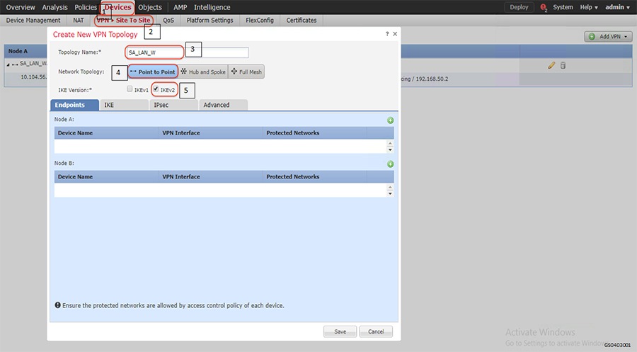
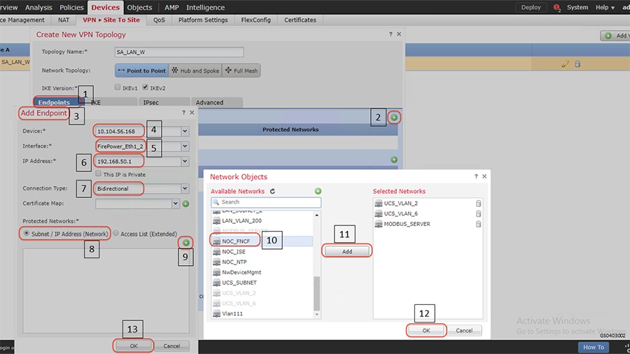
1.![]() Choose VPN Site to Site option and the related properties as highlighted in the following figure.
Choose VPN Site to Site option and the related properties as highlighted in the following figure.
Figure 13 VPN Site to Site configuration
2.![]() Add nodes between which Cisco IPSec Site to Site IPSec VPN tunnel is to be established as highlighted in the following figure. The following figure highlights the steps to be followed for Node A. Repeat the steps for Node B to establish Cisco Site to Site IPSec VPN tunnel between the nodes. Highlights 8 to 13 show the steps to select and permit the networks reachable through the Site to Site IPSec VPN tunnel.
Add nodes between which Cisco IPSec Site to Site IPSec VPN tunnel is to be established as highlighted in the following figure. The following figure highlights the steps to be followed for Node A. Repeat the steps for Node B to establish Cisco Site to Site IPSec VPN tunnel between the nodes. Highlights 8 to 13 show the steps to select and permit the networks reachable through the Site to Site IPSec VPN tunnel.
Figure 14 Adding Site to Site VPN nodes
Note: Define the details of the IKE and IPsec transforms. It is critical that the Security parameters match between two peers so that they can successfully negotiate a security association.
Verification
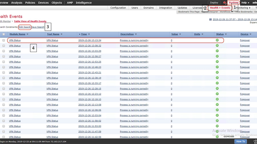
■![]() Select System > Health > Events > Edit Search and search for VPN as highlighted in the following figure.
Select System > Health > Events > Edit Search and search for VPN as highlighted in the following figure.
Figure 15 Verifying Site to Site VPN status
Login to the consoles of the FTD devices and use the following command to check the status of the established Site to Site IPSec VPN tunnel. The command helps to check the status of the tunnel, statistics of encrypted and decrypted packets, the access-list permitting traffic from networks that needs to be encrypted by the Site to Site IPSec VPN tunnel.
https://tools.cisco.com/security/center/resources/next_generation_cryptography#1
Site to Site VPN in Distribution Automation
FlexVPN is a flexible and scalable VPN solution based on IPSec and IKEv2. To secure DA data communication with the headend across the WAN, FlexVPN is recommended. The IoT FND establishes FlexVPN tunnels between the HERs and the DA Gateways as a part of the ZTD process.
FlexVPN, which integrates various topologies and VPN functions under one framework, simplifies the deployment of VPNs by providing a unified VPN framework that is compatible with legacy VPN technologies.
FlexVPN has some of the following benefits:
■![]() Allows use of a single tunnel for both IPv4 and IPv6, when the medium supports it
Allows use of a single tunnel for both IPv4 and IPv6, when the medium supports it
■![]() Supports QoS in both directions: hub-to-spoke and spoke-to-hub
Supports QoS in both directions: hub-to-spoke and spoke-to-hub
■![]() Supports Virtual Routing and Forwarding (VRF)
Supports Virtual Routing and Forwarding (VRF)
■![]() Reduces control plane traffic for costly links with support for tuning of parameters
Reduces control plane traffic for costly links with support for tuning of parameters
Note: In this solution, IPSec is configured in the tunnel mode.
■![]() KEv2 has fewer round trips in a negotiation than IKEv1: two round trips versus five for IKEv1 for a basic exchange
KEv2 has fewer round trips in a negotiation than IKEv1: two round trips versus five for IKEv1 for a basic exchange
■![]() Built-in dead peer detection (DPD)
Built-in dead peer detection (DPD)
■![]() Built-in configuration payload and user authentication mode
Built-in configuration payload and user authentication mode
■![]() Built-in NAT traversal (NAT-T). IKEv2 uses ports 500 and 4500 for NAT-T
Built-in NAT traversal (NAT-T). IKEv2 uses ports 500 and 4500 for NAT-T
■![]() Improved re-keying and collision handling
Improved re-keying and collision handling
■![]() A single Security Association (SA) can protect multiple subnets, which improves scalability. Support for Multi-SA Dynamic Virtual Tunnel Interfaces (DVTI) support on the hub.
A single Security Association (SA) can protect multiple subnets, which improves scalability. Support for Multi-SA Dynamic Virtual Tunnel Interfaces (DVTI) support on the hub.
■![]() Asymmetric authentication in site-to-site VPNs, where each side of a tunnel can have different pre-shared keys, different certificates, or on one side a key and the other side a certificate.
Asymmetric authentication in site-to-site VPNs, where each side of a tunnel can have different pre-shared keys, different certificates, or on one side a key and the other side a certificate.
In the FlexVPN model, the HER acts as the FlexVPN hub and the DA Gateways act as the FlexVPN spokes. The tunnel interfaces on the DA Gateways acquire their IP addresses from address pools configured during ZTD. These addresses only have local significance between the HER and the DA Gateways. Since the DA Gateway's tunnel addresses are both dynamic and private to the HER, NMS must address the DA Gateways by their loopback interface in this network architecture. Conversely, the DA Gateway sources its traffic using its loopback interface.
Before the FlexVPN tunnel is established, the DA Gateway can only communicate to the HER in the headend network. This is done over the WAN backhaul via a low priority default route. During FlexVPN handshake, route information is exchanged between the HER and the DA Gateway. The DA Gateway learns the headend routes (IPv4 and IPv6) through FlexVPN.
For details of implementation refer the following guide.
https://www.cisco.com/c/en/us/td/docs/solutions/Verticals/Distributed-Automation/Secondary-Substation/IG/DA-SS-IG/DA-SS-IG-doc.html#21265
Access Control
Access Control is one of the fundamental concepts of security in ICT networks. It is a method to limit access to the networks or resources or information for different users or devices. Access control systems perform identification, authentication, and authorization of users and entities by evaluating required login credentials that may include passwords, pins, bio-metric scans or other authentication factors.
Different access control models are used based on the compliance and security requirements. For Utilities, NERC-CIP lists the following:
■![]() Logical access control – Role based access control based on the user and the type of role for the user.
Logical access control – Role based access control based on the user and the type of role for the user.
■![]() Physical access control – Physical security in the form of cameras, badge readers and so on.
Physical access control – Physical security in the form of cameras, badge readers and so on.
■![]() Port Security - restrict input to an interface by limiting and identifying MAC addresses of the stations allowed to access the port.
Port Security - restrict input to an interface by limiting and identifying MAC addresses of the stations allowed to access the port.
This implementation guide focuses on logical access control model for different users and devices. To support the use cases and configuration shown in this document, Microsoft Windows 2012 R2 is configured as an Active Directory Domain Controller. Cisco ISE integrates with Active Directory (AD) as an Identity Source, which can provide user authentication and group membership. Cisco ISE also integrates with Cyber Vision Center as an Identity Source to collect grid device properties.
The following section lists various steps involved in implementation as validated in the lab.
Access control for different users
To perform the following task, you must be a Super Admin or Policy Admin.
1.![]() Integrate ISE and Active Directory. The detailed configuration of Microsoft Active Directory and integrating with ISE is beyond the scope of this document.
Integrate ISE and Active Directory. The detailed configuration of Microsoft Active Directory and integrating with ISE is beyond the scope of this document.
2.![]() ISE uses the concept of Network Device Groups to separate devices based on their type. Add individual devices like Cisco Industrial Ethernet switches to ISE and assign them to the applicable Network Device Group.
ISE uses the concept of Network Device Groups to separate devices based on their type. Add individual devices like Cisco Industrial Ethernet switches to ISE and assign them to the applicable Network Device Group.
3.![]() Configure the following on network devices that interacts with ISE for Authentication and Authorization.
Configure the following on network devices that interacts with ISE for Authentication and Authorization.
4.![]() Configure different policy elements like Dictionaries, Conditions and Results so as to build the policies that will provide the main functionality for ISE. Existing Dictionaries can be used for many of the scenarios involved in Grid Security Solution. Conditions can either be Simple or Compound. An example of a Simple condition would be to identify network devices by which zone they reside in within the Substation (ESP, Corporate Substation, or CIP/Multiservice).
Configure different policy elements like Dictionaries, Conditions and Results so as to build the policies that will provide the main functionality for ISE. Existing Dictionaries can be used for many of the scenarios involved in Grid Security Solution. Conditions can either be Simple or Compound. An example of a Simple condition would be to identify network devices by which zone they reside in within the Substation (ESP, Corporate Substation, or CIP/Multiservice).
5.![]() Configure Authentication policy on ISE. The Utility network may support many types of authentication, however the primary methods validated in this document is 802.1X and MAB for wired connections. To add this method to the policy, go to Policy > Policy Elements > Results > Authentication > Allow Protocols.
Configure Authentication policy on ISE. The Utility network may support many types of authentication, however the primary methods validated in this document is 802.1X and MAB for wired connections. To add this method to the policy, go to Policy > Policy Elements > Results > Authentication > Allow Protocols.
6.![]() Configure Authorization policy on ISE. The result of the ISE authorization policy is for a user or device to be granted (or denied) permission to access to some network resource. The Authorization Profile (accessed from Policy > Policy Elements > Results > Authorization > Authorization Profiles) is the construct used to define these end results which are ultimately pushed down to the Network Access Device which will enforce the policy.
Configure Authorization policy on ISE. The result of the ISE authorization policy is for a user or device to be granted (or denied) permission to access to some network resource. The Authorization Profile (accessed from Policy > Policy Elements > Results > Authorization > Authorization Profiles) is the construct used to define these end results which are ultimately pushed down to the Network Access Device which will enforce the policy.
7.![]() For the purpose of validation, an Authorization Profile is applied for users in the "Administrator" Active Directory group that access the network through devices in the ESP zone. This profile applies network access control by using a downloadable access control list (DACL) that is dynamically pushed down to the IE switch.
For the purpose of validation, an Authorization Profile is applied for users in the "Administrator" Active Directory group that access the network through devices in the ESP zone. This profile applies network access control by using a downloadable access control list (DACL) that is dynamically pushed down to the IE switch.
For detailed steps with various capabilities refer to the following guide:
https://www.cisco.com/c/en/us/td/docs/security/ise/2-4/admin_guide/b_ise_admin_guide_24/b_ise_admin_guide_24_new_chapter_010010.html
Verification
Port Security for different devices
To protect the Utility Network from being exploited, unused ports of all LAN switches or routers at the substation must be shut down by default as defined in NERC-CIP. In-use ports must be explicitly enabled. For those ports that are enabled, port security should be configured to protect the network from LAN-based attacks. This feature limits the number of MAC addresses that can connect to a switch or router and ensures that only approved MAC addresses are able to access the switch or router. Port security prevents MAC address flooding and ensures that only approved users can log onto the network. Allowed MAC addresses can either be statically configured or dynamically learned.
The following security policy applies to port security configuration:
■![]() The maximum number of secure MAC address for a port is one (1).
The maximum number of secure MAC address for a port is one (1).
■![]() For IED or other IP-enabled control devices, specify a static MAC address.
For IED or other IP-enabled control devices, specify a static MAC address.
■![]() In case IED MAC is unknown in certain deployment scenarios, specify sticky port security.
In case IED MAC is unknown in certain deployment scenarios, specify sticky port security.
■![]() For onsite engineer/technician device access in the substation, only authenticated users are permitted access via the designated user access port (802.1x).
For onsite engineer/technician device access in the substation, only authenticated users are permitted access via the designated user access port (802.1x).
In this example, the GigabitEthernet1/11 interface is configured with port-security. The port will listen for the first MAC address that tries to communicate on the port. The switch will dynamically learn this address and start permitting it t0 communicate. The “sticky” configuration allows the dynamically learned address to be saved to the configuration so that it will survive a reload of the switch; otherwise dynamically learned addresses will be forgotten. By default, the switch will only allow a single secure MAC address on an interface. The violation command configures the action to take if an un configured MAC address tries to communicate on the port. In this case, “restrict” is configured so that frames from unknown MACs will be dropped and SYSLOG message and SNMP trap are generated.
This is very useful because the switch can be configured to allow secure devices (such as RTUs, IEDs, etc.) to connect. However, if a malicious person unplugs a secure device and tries to connect another device, it will immediately be denied access to the network. The log message below shows a violation when an unknown MAC tries to connect:
Grid Visibility
As discussed previously in this document, one of the important NERC-CIP requirements is to identify and categorize Cyber system assets. This requirement can be met with the Cisco Cyber Vision Center and Cyber Vision sensor.
The Cisco Cyber Vision solution is based on a 2-tier architecture made of inline network sensors namely Cisco IE3400 and Cisco IR1101, as well as a dedicated hardware sensor like Cisco IC3000. These sensors are dedicated to capture network traffic using various SPAN features, decode SCADA protocols as listed in the following table along with other supported IT protocols using the Cisco Deep Packet Inspection engine and send meaningful information to the Cisco Cyber Vision Center for passive monitoring. Support for visibility of legacy protocols is restricted to Cisco IR1101 as Cyber Vision Network sensor.
Table 5 SCADA Protocols supported by Cisco Cyber Vision
|
|
|
|---|---|
| T101 to T104 (Enabled by SCADA Protocol Translation on Cisco IR1101) |
|
Cisco Cyber Vision also enables visibility to the type of devices or components that are part of the network, the flows they generate. For e.g., the flow could be that of between a SCADA front end processor and its client like control commands, poll, and so on. The details of the device could be that of the type of the device like PLC or SCADA station or PC as appropriate, properties of the device like IP Address, Operating System, Manufacturer, etc. as can be derived from the flows or communication generated by the devices in the network. The figure highlights some of the details that could be deduced with the use of Cisco Cyber Vision. The Cisco Cyber Vision Center, a central platform gathers data from all the Edge Sensors across the network and acts as the monitoring, detection and management platform for the solution.
To operate, the Center relies on two separate networks, respectively connected to the following interfaces:
■![]() The Administration network interface, which gives access to the user interface.
The Administration network interface, which gives access to the user interface.
■![]() The Collection network interface, which connects the Center to the sensors.
The Collection network interface, which connects the Center to the sensors.
The Cisco Cyber Vision solution success depends on effectively capturing the traffic. Where to capture the traffic in a network is critical.
The following figure highlights the different sensors and traffic flow in the network that gets captured by the sensor and sent to the Center.
Figure 16 Grid Visibility Center and Sensors
Sensors in Substation LAN
IC3000
Positioning IC3000 as Sensor
In addition to a management port, the IC3000 contains 4 independent data capture ports (two RJ45 copper ports and two SFP fiber ports) operating in SPAN mode, each of which can be connected to an on-site switch. The IC3000 data capture ports should be connected to switches with SPAN configured. This section explains the positioning of IC3000 as hardware sensor to capture traffic flowing in an HSR ring.
As per the following topology one of the ports of IC3000 positioned as Hardware sensor connects to IE4000 switches as required in the HSR ring and processes east-west traffic communication in the network while the IE3400 positioned as Network sensor processes north-south communication in the network. The copper ports of IC3000, int1 or int2, are used to connect to these switches with SPAN configured to mirror the respective source and destination port traffic for inspection by the sensor application hosted on the IC3000 and forward the metadata to CVC for further processing.
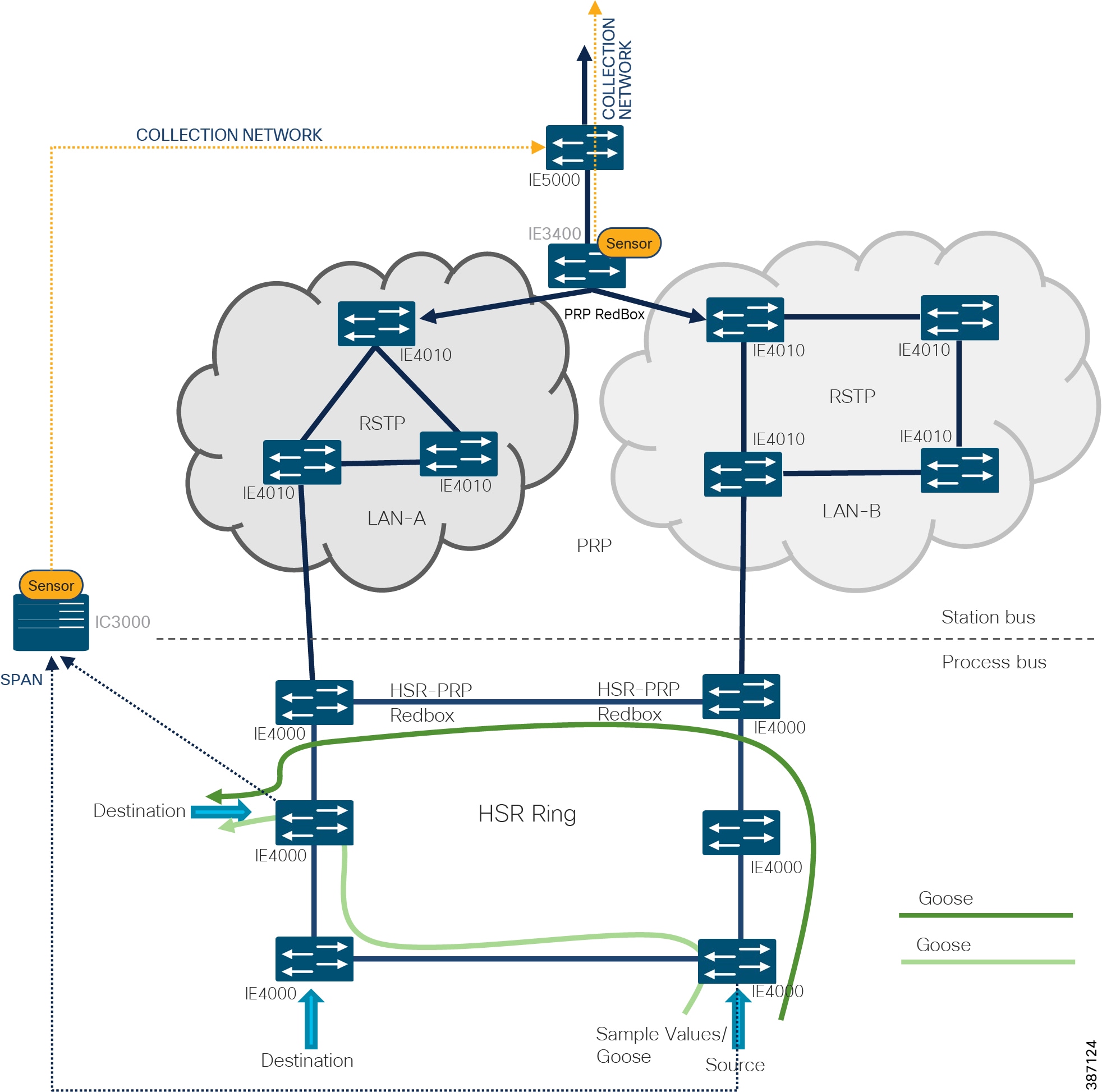
After the sensor application on IC3000 gets registered to CVC, traffic starts to appear in CVC provided the SPAN ports of IC3000 are properly connected to those network switches having SPAN configured. Below section shows the sample switch configuration on IE4000 needed to inter-connect the IC3000 hosting sensor application with a SCADA system (Front End Processor or Controller or SCADA Outstation or IED) and thereafter enabling SPAN so that the sensor can process the incoming SCADA system traffic and report it to CVC.
Note: While the recommendation is to use SPAN configuration on the IE switches to forward a copy of the network traffic to the Cyber Vision Sensor, it is important to note that currently RSPAN is not supported over an HSR ring network due to the DDTS CSCvr81772.
Configuring IC3000 as Hardware Sensor
This section focuses on the components listed below discussing the interactions between the Cisco Cyber Vision Sensor application hosted on the IC3000 and the Cisco Cyber Vision Center used for managing the sensor application in order to provide Grid visibility.
■![]() Cisco IC3000 Industrial Compute Gateway
Cisco IC3000 Industrial Compute Gateway
■![]() Cisco Cyber Vision Sensor (CVS) application
Cisco Cyber Vision Sensor (CVS) application
■![]() Cisco Cyber Vision Center (CVC)
Cisco Cyber Vision Center (CVC)
The IC3000 Industrial Compute Gateway (IC3000) is an edge computing platform which extends the cloud computing paradigm to the edge of the network. It comes as a mid-range, low-power, fanless, edge server ruggedized for Industrial Applications powered by a 4 core 1.2GHz Intel Rangeley CPU with 8 GB of 1333MHz DDR3 memory, and a 100GB mSATA drive (internal). For connectivity purpose it supports 2x1GbE SFP and 2x10/100/1000Base-T with a management port.
For more details about the product, please refer to the link below:
https://www.cisco.com/c/en/us/support/routers/3000-series-industrial-compute-gateways/tsd-products-support-series-home.html
The IC3000 can be ordered with the Cisco Cyber Vision sensor application, which comes pre-installed by manufacturing. The Cisco Cyber Vision sensor application allows traffic from the network to be captured in offline or online mode. This captured data can be viewed from Cisco Cyber Vision Center.
This guide focuses on the online mode of operation of Cisco Cyber Vision Sensor. As a pre-requisite it is recommended to have the Cisco Cyber Vision Center installed and running first. For details on setting up the CVC, please refer to the Cisco Cyber Vision Center quick start guides at the link below.
https://www.cisco.com/c/dam/en/us/td/docs/security/cyber_vision/Cisco_Cyber_Vision_Center_Appliance_Quickstart_Guide_Release_3_0_0.pdf
Figure 18 illustrates the IC3000 based hardware sensor’s collection network and the available SPAN interfaces on the platform.
Figure 18 Cisco IC3000 based hardware sensor
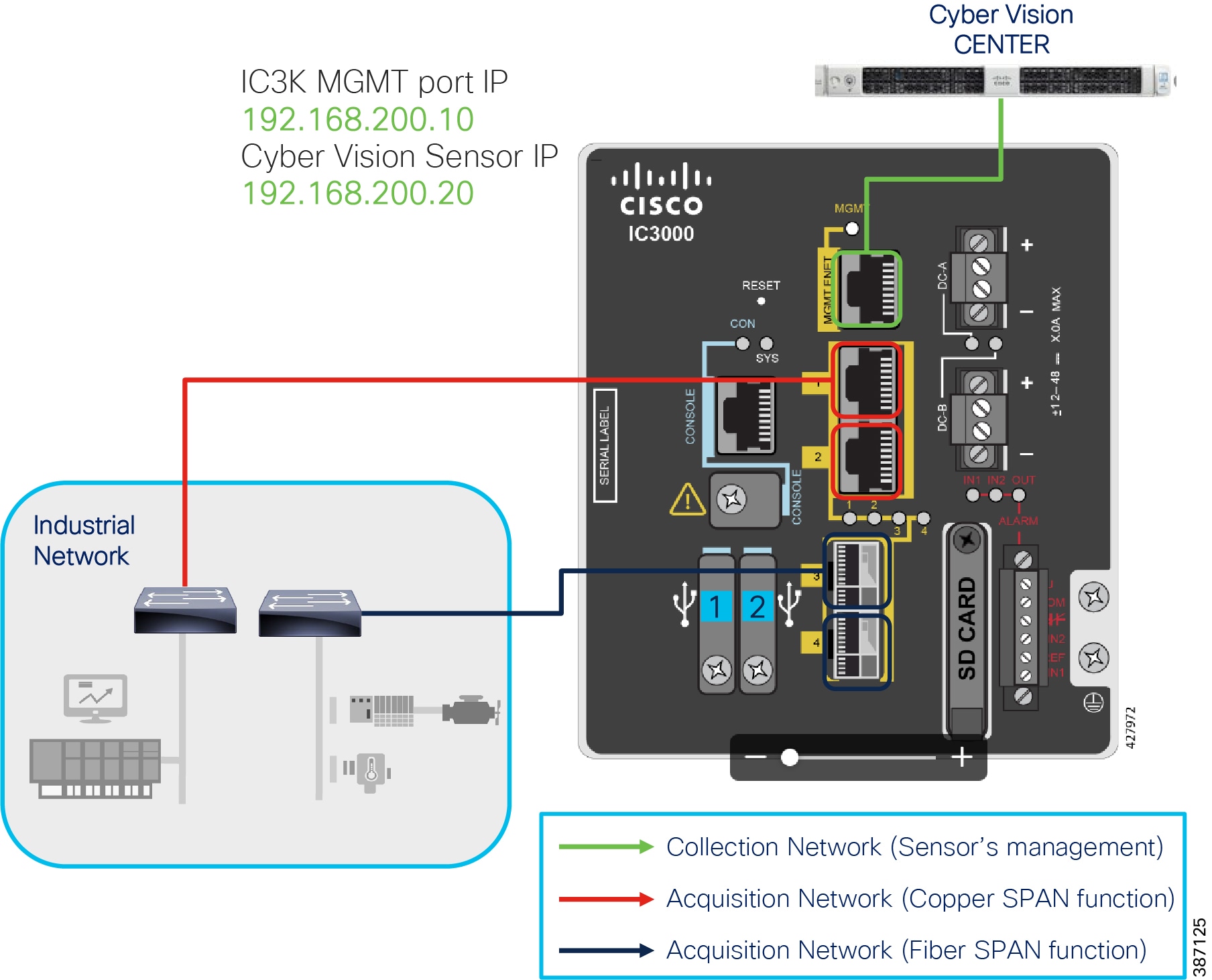
As shown in the figure above, the IC3000 management port is connected to the collection network from where CVC is reachable. Whereas the copper SPAN ports are plugged into the switches with SPAN pre-configured to mirror the network traffic for inspection by the sensor hosted on the IC3000. This section focuses on the manual deployment of sensor onto the IC3000 platform using a USB device. In a later section, the CVC extension feature is used for deploying the sensor onto IC3000 platform.
The following IP address schema has been used in this guide to bring up the CVS application on IC3k and integrate it to the CVC.
–![]() Admin Interface (eth0): 192.168.3.113
Admin Interface (eth0): 192.168.3.113
–![]() Collection interface (eth1): 192.168.169.1
Collection interface (eth1): 192.168.169.1
–![]() Collection network gateway: 192.168.169.100
Collection network gateway: 192.168.169.100
–![]() Host Mgmt. IP address: 192.168.200.10
Host Mgmt. IP address: 192.168.200.10
–![]() Host Mgmt. netmask: 255.255.255.0
Host Mgmt. netmask: 255.255.255.0
–![]() Host Mgmt. gateway: 192.168.200.100
Host Mgmt. gateway: 192.168.200.100
–![]() Sensor IP address: 192.168.200.20
Sensor IP address: 192.168.200.20
To bring up the IC3000 with sensor application (CVS) in online mode and have it registered with the CVC, please refer to the section “Cyber Vision Sensor Application in Online Mode” inside the Cisco Cyber Vision Sensor deployment guide using the link:
https://www.cisco.com/c/en/us/td/docs/routers/ic3000/deployment/guide/DeploymentGuide-Cyber.htm l
Note that the process documented in the deployment guide above works fine when the CVC collection network and IC3000, sensor application management IP addresses are in same subnet. However, if they are in different subnets as shown in the IP schema above, then additionally a persistent static route needs to be added on the CVC as shown below to ensure reachability between CVC and the sensor application.
1.![]() To do this login to the CVC console by connecting to the admin interface using ssh.
To do this login to the CVC console by connecting to the admin interface using ssh.
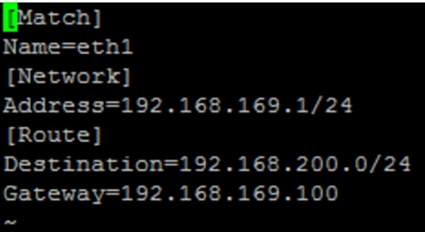
2.![]() Navigate to the /data/etc/systemd/network/ directory and edit the 00-eth1-static.network file to add a static route as shown below.
Navigate to the /data/etc/systemd/network/ directory and edit the 00-eth1-static.network file to add a static route as shown below.
Figure 19 Network file to add a static route

In this guide, the destination and gateway entries below have been used for the route entries.
Figure 20 Static route entry added
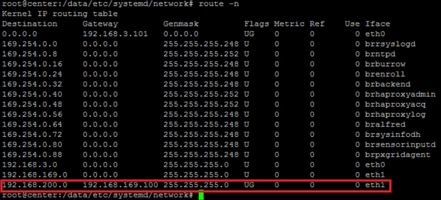
3.![]() Reboot the system by issuing a reboot command on the cli.
Reboot the system by issuing a reboot command on the cli.
4.![]() After reboot, check the routing table to verify that the sensor subnet could be reached by the CVC collection interface (eth1).
After reboot, check the routing table to verify that the sensor subnet could be reached by the CVC collection interface (eth1).
To connect to the IC3000 via the console port, refer to the section “Unboxing, Installing and Connecting to the IC3000 Device” in the Cisco IC3000 Industrial Compute Gateway Deployment Guide using the link below:
https://www.cisco.com/c/en/us/td/docs/routers/ic3000/deployment/guide/DeploymentGuide.html
The IC3000 is shipped with a factory installed image. Once the device is properly connected and powered up, the ic3k> prompt is visible. The version installed can be verified by running the show version command via the console.
Similarly, the IP address obtained by IC3000 can be verified by running the show interfaces command and looking for the svcbr_0 interface details.
Verify the reachability between IC3000 and CVC with a ping command from IC3000 as shown below:
The previous section provided details deploying the sensor application on the IC3000 using the provisioning package. The package is downloaded from CVC to a USB device which is later inserted into the IC3000 hardware. With the latest CVC version, there is another cleaner and easier way to deploy the sensor application on the IC3000 hardware sensor (and even on other network-based sensor platforms like IE3400, IR1101) via the CVC Extension feature.
Note: The extension is not included in the center update and must be manually imported to the CVC under the Admin -> Extensions tab before using it for sensors deployment. The prerequisite for sensor deployment using the extension is that the IC3000 must be pre-configured with an IP address that is reachable from the Center. Refer to the Cisco IC3000 Industrial Compute Gateway Deployment guide here:
https://www.cisco.com/c/en/us/td/docs/routers/ic3000/deployment/guide/b_IC3000_deployment_guide.html
Focus on the section Remote Device Management in the document linked below, which describes managing the device remotely over a non-link local address depending on the network topology.
https://www.cisco.com/c/en/us/td/docs/routers/ic3000/deployment/guide/b_IC3000_deployment_guide/b_IC3000_deployment_guide_chapter_011.html#task_1076567
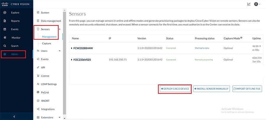
Once this is in place, deploying the sensor application onto IC3000 from the CVC is straight-forward. Login to the CVC web GUI and navigate to Admin tab on the left and click on Sensors -> Management -> Deploy Cisco device as shown below.
Figure 22 CVC Sensors management
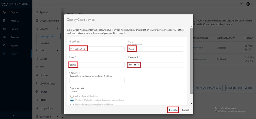
As a next step, fill in the details about the IC3000 like ip address, port number, username and password and then click on Deploy as shown below.
Figure 23 Deploy Cisco Device - IC3000
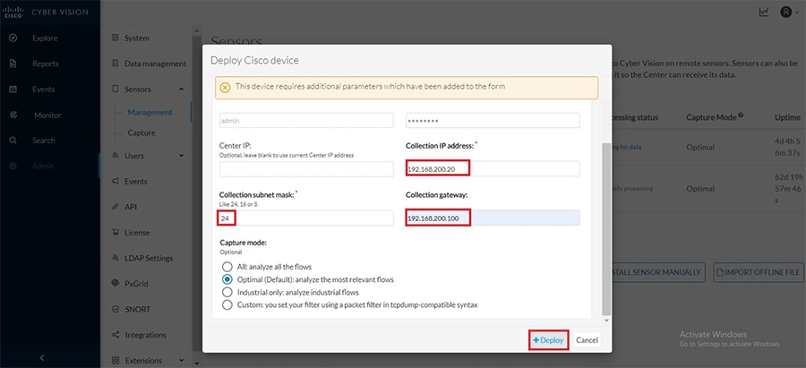
At this point if the reachability between CVC and IC3000 is intact, additional parameters would be requested about the sensor application being deployed onto IC3000 as shown below. Fill in these details like the address, subnet mask and the gateway address for the sensor and click on the Deploy button as shown below.
Figure 24 Sensor deployment on IC3000
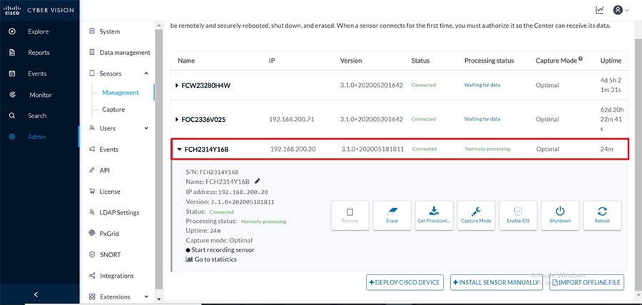
After successful deployment the sensor shows in the list of managed sensors in the CVC as shown below.
Figure 25 Managed sensors in CVC
IE3400
Positioning IE3400 as Sensor
Figure 7 shows the overall Grid Security solution topology where IE3400 is located inside the Substation LAN – ESP zone within the Transmission substation. The following figure gives a closer look of IE3400 positioning within ESP zone in the overall Grid Security solution topology. Here IE3400 is positioned as a Parallel Redundancy Protocol (PRP) node. PRP is used to provide hitless redundancy (zero recovery time after failures) in Ethernet networks and comprises a scheme where the end nodes implement redundancy (instead of network elements connected in mesh or ring topologies using protocols like RSTP, REP, or MRP) by connecting two network interfaces to two independent, disjointed, parallel networks. Such end nodes are referred to as Dually attached nodes (DANs) and each of them have redundant paths to all other DANs in the network.
The DAN sends two packets simultaneously through its two network interfaces to the destination node. A redundancy control trailer (RCT), which includes a sequence number, is added to each frame to help the destination node distinguish between duplicate packets. When the destination DAN receives the first packet successfully, it removes the RCT and consumes the packet. If the second packet arrives successfully, it is discarded. If a failure occurs in one of the paths, traffic continues to flow over the other path uninterrupted, and zero recovery time is required.
A Redundancy Box (RedBox) is used when an end node that does not have two network ports and does not implement PRP needs to implement redundancy. Such an end node can connect to a RedBox, which provides connectivity to the two different networks on behalf of the device.
In this solution, IE3400 switch implements PRP Redbox functionality using Gigabit Ethernet port connections to each of the two LANs. PRP channel or channel group is a logical interface that aggregates two Gigabit Ethernet interfaces (access, trunk, or routed) into a single link. In the channel group, the lower numbered Gigabit Ethernet member port is the primary port and connects to LAN_A. The higher numbered port is the secondary port and connects to LAN_B. The PRP channel remains up as long as at least one of these member ports remains up and sends traffic. When both member ports are down, the channel is down.
Figure 26 Cisco IE3400 sensor IOx Application Interface Mapping
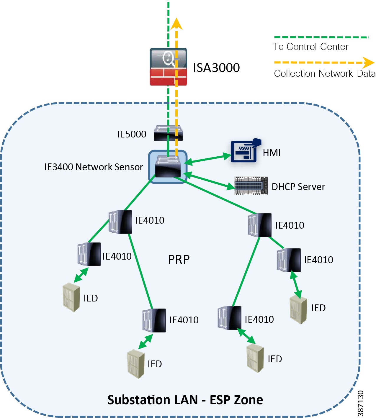
As shown in Figure 26, the IE3400 is connected to a single IE5000 switch using one of its Gigabit ethernet ports (Gi 1/8) configured as a trunk. The other side is connected to two adjacent IE4010 aggregation type switches via a Gigabit ethernet port each (Gi 1/1 & Gi 1/2). These two ports together are configured as a PRP channel link. Figure 40 shows this configuration.
Notice the remote-span VLAN 2508 on IE3400 configured previously during sensor application install being excluded from all the trunk ports that are permitted to carry all other VLAN traffic flowing in the network. The necessary SPAN configuration needed for traffic to be mirrored to the sensor application on the IE 3400 is shown below:
After the PRP configuration is in place on the IE3400, any SCADA Controller or Front End Processor can then connect to the IE5000 switch. This switch is placed on top of the IE3400 and communicates through this IE3400. It acts as a PRP Redbox providing two redundant paths to the SCADA Outstation (IED) connected to the lowest IE4010 switches within the Substation LAN.
Note: The complete configuration for the IE5000 and the IE4010 switch connected to PRP Redbox switch (IE3400) has been provided in the Appendix B and C for reference.
https://www.cisco.com/c/en/us/td/docs/switches/lan/industrial/software/configuration/guide/b_prp_ie4k_5k.html#id_42563
Note: The complete configuration of IE3400 has been provided in the Appendix A for reference.
Configuring IE3400 as Network Sensor
This section focuses on the components listed below discussing the interactions between the Cisco Cyber Vision Sensor application hosted on the IE3400 and the Cisco Cyber Vision Center used for managing the sensor application in order to provide Grid visibility.
■![]() Cisco Catalyst IE3400 Rugged Switch
Cisco Catalyst IE3400 Rugged Switch
■![]() Cisco Cyber Vision Sensor (CVS) application
Cisco Cyber Vision Sensor (CVS) application
■![]() Cisco Cyber Vision Center (CVC)
Cisco Cyber Vision Center (CVC)
The Cisco Catalyst IE3400 Rugged Series switches deliver advanced, high-speed Gigabit Ethernet connectivity in a compact form factor, and are designed for a wide range of industrial applications where hardened products are required. These switches extend intent-based networking to the IoT edge of the network. The modular design of the Cisco Catalyst IE3400 Rugged Series offers the flexibility to expand up to 26 ports of Gigabit Ethernet with a range of expansion module options.
The IE3400 Series runs Cisco IOS® XE, a next-generation operating system with built-in security and trust and can be managed with powerful management tools such as Cisco DNA Center and Industrial Network Director, and can be easily set up with a completely redesigned, user-friendly, modern GUI tool called WebUI.
For more details about the product, please refer to the link below:
https://www.cisco.com/c/en/us/products/switches/catalyst-ie3400-rugged-series/index.html
This guide describes how to perform a clean installation of the sensor application (CVS) on an IE3400 switch. As a pre-requisite it is recommended to have the Cisco Cyber Vision Center installed and running.
The figure below illustrates the IE3400 sensor collection network, SPAN interfaces, ERSPAN configurations as applicable.
Figure 27 Cisco IE3400 network sensor IOx Application Interface Mapping
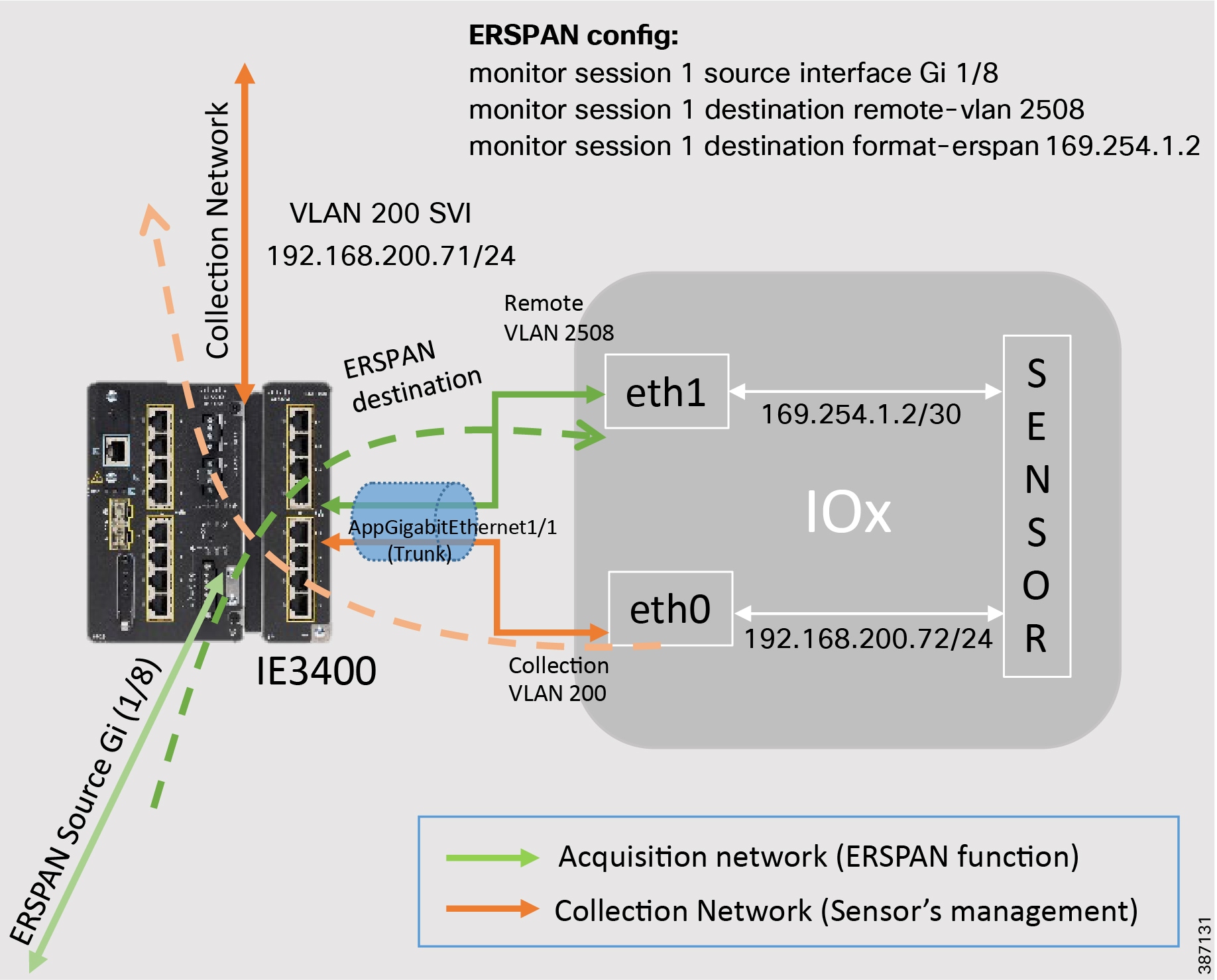
As shown in Figure 27, the network traffic traversing one of the physical ports on IE3400 (configured as ERSPAN source) is mirrored to the IOx based sensor which listens on port eth1. The sensor communicates to the CVC by connecting to the collection network using its eth0 port and also sends metadata of the inspected traffic to CVC for further processing.
The following IP address schema is used to bring up the CVS application on IE3400 and integrate it to the CVC.
■![]() Admin Interface (eth0): 192.168.3.113
Admin Interface (eth0): 192.168.3.113
■![]() Collection interface (eth1): 192.168.169.1
Collection interface (eth1): 192.168.169.1
■![]() Admin IP address: 192.168.200.71
Admin IP address: 192.168.200.71
■![]() Capture IP address: 169.254.1.2
Capture IP address: 169.254.1.2
■![]() Collection IP address: 192.168.200.72
Collection IP address: 192.168.200.72
■![]() Collection gateway: 192.168.200.100
Collection gateway: 192.168.200.100
The prerequisite the sensor application installation on the IE3400 is to configure the switch for access to the CLI (ssh or console port).
Below are the configuration prerequisites needed on IE3400 before installing the Sensor:
■![]() Factory reset of the IE3400 (optional)
Factory reset of the IE3400 (optional)
■![]() Console cable for connection to the IE3400 console port
Console cable for connection to the IE3400 console port
■![]() Ethernet cable for the connection to one of the IE3400 port
Ethernet cable for the connection to one of the IE3400 port
■![]() IP addresses to be assigned to the IE3400 switch
IP addresses to be assigned to the IE3400 switch
1.![]() Establishing a Serial connection
Establishing a Serial connection
–![]() Establish the connection with the IE3400 on the console port (9600 baud).
Establish the connection with the IE3400 on the console port (9600 baud).
a.![]() Press and hold the Express Setup button for 15 seconds or more. The switch reboots. The system led turns green and the express setup led starts to blink green.
Press and hold the Express Setup button for 15 seconds or more. The switch reboots. The system led turns green and the express setup led starts to blink green.
b.![]() Press the Express Setup button again for 1-3 seconds. LED for port 1/1 blinks green.
Press the Express Setup button again for 1-3 seconds. LED for port 1/1 blinks green.
The switch now behaves like a factory-default configured switch. To keep a default configuration, answer “no” to the first question, then “yes” to the second one as shown below.
Figure 28 System Config Dialog on IE3400
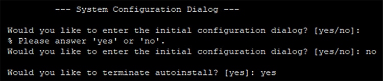
–![]() Establish the connection with the IE3400 on the console port (9600 baud).
Establish the connection with the IE3400 on the console port (9600 baud).
Figure 29 Console access on IE3400
First enable the CLI, then go into the configuration terminal to setup a name to the switch and a password using the commands below.
4.![]() Define switch ssh access and security parameters:
Define switch ssh access and security parameters:
Type the following command to set the IP address to access the device via SSH:
Add necessary security parameters:
5.![]() Test ssh access to the switch
Test ssh access to the switch
Test ssh connection to the IE3400 by connecting to the ip address configured. In this example it is 192.168.200.71. During login use the previously configured admin username and password and verify SSH connection works.
To bring up the IE3400 with sensor application (CVS) and have it registered with the CVC with the IP address schema mentioned earlier, follow steps 1 to 4 inside Section 3 “Procedure with the Local Manager” in the Cisco Cyber Vision IE3400 and CAT9300 installation guide available at the below link:
https://www.cisco.com/c/dam/en/us/td/docs/security/cyber_vision/Cisco_Cyber_Vision_IE3400_and_CAT9300_Installation_Guide_Release_3_1_0.pdf
Once the above pre-requisite configurations on IE3400 are completed, proceed to Section 3 “Procedure with the Local Manager” in the Cisco Cyber Vision IE3400 and CAT9300 installation guide available at the below link. Specifically, just implement steps 1-4 shown in the guide as relevant to IE3400 on the previously configured IE3400 switch.
https://www.cisco.com/c/dam/en/us/td/docs/security/cyber_vision/Cisco_Cyber_Vision_IE3400_and_CAT9300_Installation_Guide_Release_3_1_0.pdf
Configure the IE3400 links with the necessary VLAN and SPAN configurations as shown below. This step is necessary before beginning to install the sensor application from the CVC onto the IE3400 switch.
1.![]() Open the IE3400 CLI through ssh or via the console terminal, and first configure a vlan for the traffic mirroring. To do this type:
Open the IE3400 CLI through ssh or via the console terminal, and first configure a vlan for the traffic mirroring. To do this type:
2.![]() Then configure the appgigabitEthernet port which enables the communication to the IOx virtual application using below commands
Then configure the appgigabitEthernet port which enables the communication to the IOx virtual application using below commands
3.![]() The SPAN session needs to be configured, interfaces which need to be monitored need to be added in the session as shown below
The SPAN session needs to be configured, interfaces which need to be monitored need to be added in the session as shown below
4.![]() One of the switch ports needs to be configured to enable the communication between the virtual sensor and the center. To do this type:
One of the switch ports needs to be configured to enable the communication between the virtual sensor and the center. To do this type:
5.![]() Finally, the configuration needs to be saved as shown below
Finally, the configuration needs to be saved as shown below
Finally to bring up the IE3400 with sensor application (CVS) and have it registered with the CVC using the IP address schema mentioned earlier, proceed to Section 5 “Procedure with the CLI and the Cyber Vision sensor management extension” within the Cisco Cyber Vision IE3400 and CAT9300 installation guide available at the below link. Follow all the steps listed under this section post which CVS application would get installed on IE3400 and after a few minutes the sensor will appear as connected in the CVC.
https://www.cisco.com/c/dam/en/us/td/docs/security/cyber_vision/Cisco_Cyber_Vision_IE3400_and_CAT9300_Installation_Guide_Release_3_1_0.pdf
Note: The complete configuration of IE3400 has been provided in the Appendix A for reference.
Sensors in Distribution Automation
IR1101
Positioning IR1101 as Sensor
As shown in the following topology, the Cisco IR1101 is connected via cellular backhaul over FlexVPN to Head End Router on DMZ. In the figure SCADA FEP as the DSO Control Center connects to HER and communicates with SCADA IED connected to Secondary Substation Router Cisco IR1101 over IPSec FlexVPN tunnel established over Cellular connection.
Figure 30 IR1101 Secondary Substation Router as Cisco Cyber Sensor
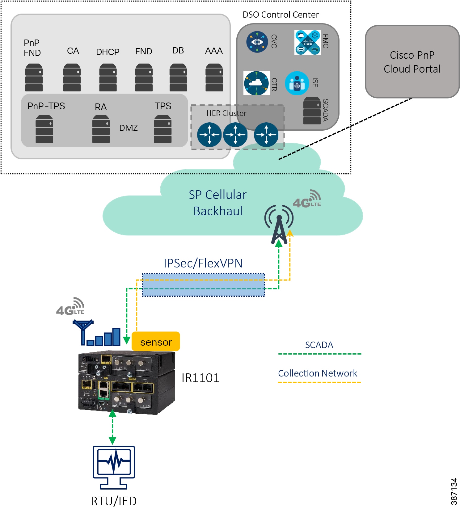
As per the topology shown in the above figure, Cisco IR1101 is positioned as the Secondary Substation router or DA gateway, and we have the IR1101 Cellular gateway with single LTE radio connected and FlexVPN Tunnel0 over primary LTE module is established and terminates on the HER cluster. SCADA, FND, CVC and other control center/utility applications are advertised via Tunnel0. Once the FlexVPN tunnel0 is established with the HER cluster, and with necessary routes advertised via Tunnel0, the communication could now happen with the Control center in a secure fashion.
Requirement for Inter-HER Routing Protocol in Control Center
Virtual Access interface on HER side corresponds to the (peer side of) the FlexVPN Tunnel0 interface on the IR1101. A routing protocol should be run between the HERs in the HER cluster, redistributing the virtual-access interfaces terminating on each HER. The goal is to make all HERs aware of the FlexVPN tunnels terminating on all other HERs, and to enable consistent routing of return traffic via the appropriate HER.
After enabling the end to end reachability between IR1101 and Head End, the application traffic will be encrypted by FlexVPN tunnel0. The encrypted traffic is monitored and redirected to the CVC by sourcing the tunnel interface of IR1101 on the ERSPAN and allowing the IOx to reach the CVC by enabling NAT on the VirtualPortGroup1 via Tunnel interface.
As per the Figure 27, The IR1101 is connected to the RTU/IEDs using Gig/FE interface, CVC and SCADA FEP is connected via Cellular backhaul over FlexVPN tunnel. The complete configuration of Cisco IR1101 and HER is provided in the Appendix C and D section of this guide.
Configuring IR1101 as Sensor
This section focuses on the components listed below discussing the interactions between the Cisco Cyber Vision Sensor application hosted on the IR1101 and the Cisco Cyber Vision Center used for managing the sensor application in order to provide Grid visibility.
■![]() Cisco IR1101 Integrated Services Router Rugged
Cisco IR1101 Integrated Services Router Rugged
■![]() Cisco Cyber Vision Sensor (CVS) application
Cisco Cyber Vision Sensor (CVS) application
■![]() Cisco Cyber Vision Center (CVC)
Cisco Cyber Vision Center (CVC)
Cisco Cyber Vision Sensor application can be hosted as an Edge compute in IOX. Regular IOS perform the operation of routing the SCADA traffic. Sensor applications installed on IOX perform the role of passive sensor. The sensor application hosted on IR1101 needs two interfaces, one to connect the sensor to the collection network interface of the Cyber Vision Center and one to monitor the traffic on local IOS interfaces.
Cisco IR1101 IOx uses VirtualPortGroup as means to communicate between IOS and the IOx application. A logical mapping of VirtualPortGroup and IOx Application is shown in the following figure. This guide proposes to use Encapsulated Remote Switched Port Analyzer (ERSPAN) to monitor traffic on one or more routed ports or routed Switch Virtual Interfaces (SVI).
The ERSPAN source sessions copy traffic from the source routed ports or SVIs and forwards the traffic using routable GRE-encapsulated packets to the ERSPAN destination session, the Cisco Cyber Vision Sensor application in this solution. Similarly, the application uses a separate interface to send the processed traffic to the collection network interface.
To enable reachability of the collection network interface of the Center for the sensor, its recommended to enable NAT on the VirtualPortGroup and overload using the IR1101 WAN facing interface. This section describes how to perform a clean installation of the sensor application (CVS) on Cisco IR1101. As a pre-requisite it is recommended to have the Cisco Cyber Vision Center installed and running.
Figure 31 Cisco IR1101 IOX Sensor interface mapping
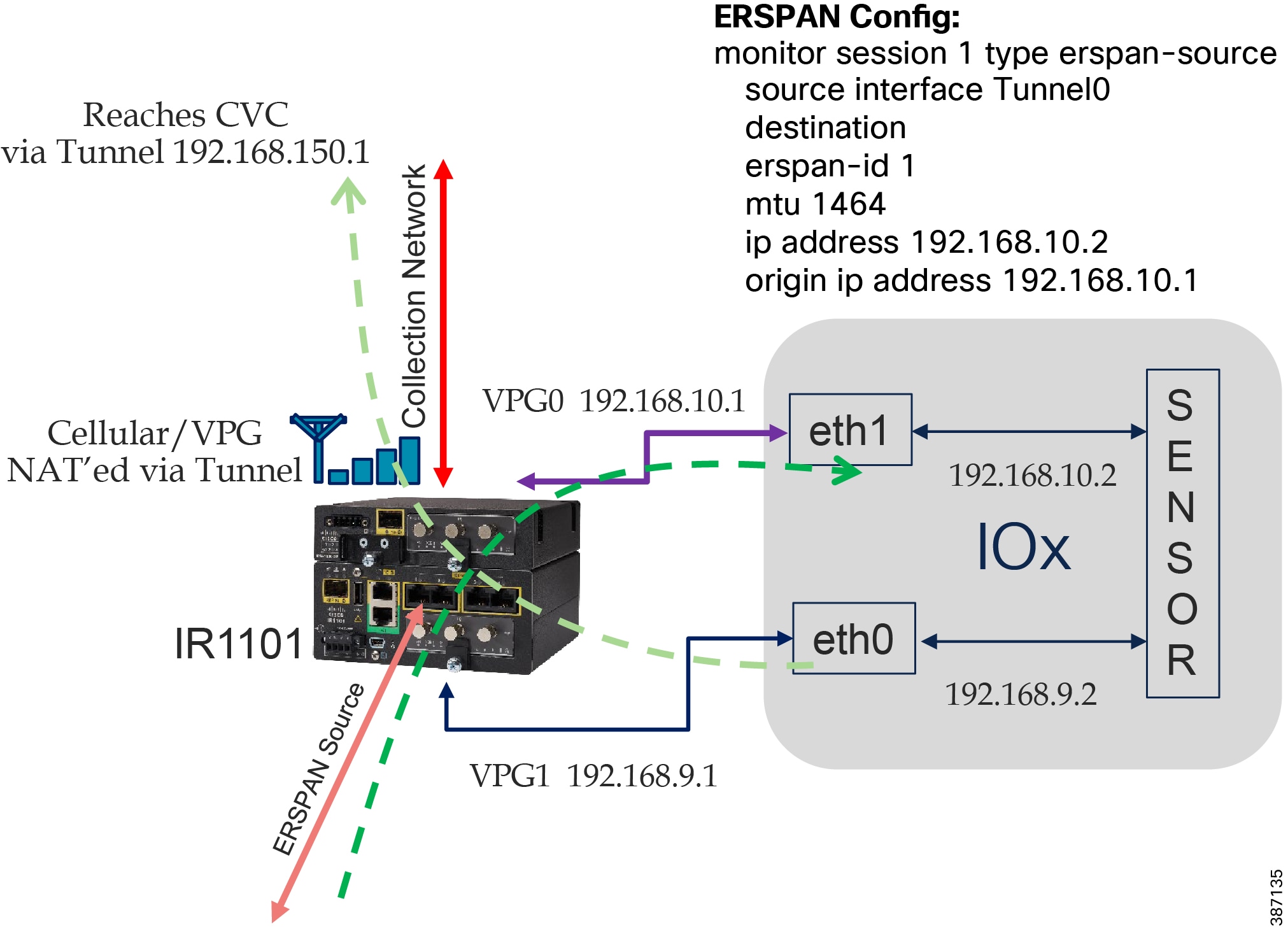
The following IP address schema has been used in this guide to bring up the CVS application on IR1101 and integrate it to the CVC as highlighted in the above figure.
■![]() Admin Interface (eth0): 192.168.117.11
Admin Interface (eth0): 192.168.117.11
■![]() Collection interface (eth1): 192.168.109.109
Collection interface (eth1): 192.168.109.109
■![]() Collection network gateway: 192.168.109.1
Collection network gateway: 192.168.109.1
■![]() Admin IP address: 192.168.150.16
Admin IP address: 192.168.150.16
■![]() Capture IP address: 192.168.10.2
Capture IP address: 192.168.10.2
■![]() Collection IP address: 192.168.9.2
Collection IP address: 192.168.9.2
■![]() Collection gateway: 192.168.9.1
Collection gateway: 192.168.9.1
Now for the sensor application install on IR1101, the prerequisite is to configure the switch for access to the CLI (ssh or console port).
Below are the configuration prerequisites needed on IR1101 before installing the Sensor:
■![]() Factory reset of the IR1101 (optional)
Factory reset of the IR1101 (optional)
To bring up the IR1101 with sensor application (CVS) and have it registered with the CVC with the IP address schema mentioned earlier, follow steps 3. 1 to 3.5 inside Section 3 “Procedure with the Local Manager” inside the Cisco Cyber Vision IR1101 installation guide in below link.
https://www.cisco.com/c/dam/en/us/td/docs/security/cyber_vision/Cisco_Cyber_Vision_IR1101_Installation_Guide_Release_3_1_0.pdf
Below steps show the necessary configuration needed on IR1101 for the sensor application deployed to then register with the CVC.
1.![]() Setup ERSPAN (Encapsulated Remote Switched Port ANalyzer). In order to receive traffic inside an IOx application, you should make sure the app is connected to a VirtualPortGroup, and has the correct IP address by issuing the following commands.
Setup ERSPAN (Encapsulated Remote Switched Port ANalyzer). In order to receive traffic inside an IOx application, you should make sure the app is connected to a VirtualPortGroup, and has the correct IP address by issuing the following commands.
And finally, create the monitor session,
We need to add NAT rules so that the container can ping the outside. This will be on a different virtual port group than the ERSPAN to separate the traffic.
Configure Access-list for the VirtualPortGroup1 to reach outside the container via tunnel interface.
3.![]() Finally, the configuration needs to be saved as shown below
Finally, the configuration needs to be saved as shown below
After a few minutes the sensor will now appear connected in Cisco Cyber vision after following any one of 3 ways to install sensor on Cisco IR1101 as mentioned in “Cisco Cybervision IR1101 installation Guide”.
After the pre-requisites are met (section 2 and section 3.1 to 3.5), there are 3 ways we can install Cyber Vision Sensor on IR1101.
1.![]() Via Local Manager – Follow Section 3.6 to 3.10 on above guide
Via Local Manager – Follow Section 3.6 to 3.10 on above guide
2.![]() Via CLI – Follow section 4.1 to 4.3
Via CLI – Follow section 4.1 to 4.3
3.![]() Via Cisco Cyber Vision Center Extension – Follow section 5.1 to 5.2
Via Cisco Cyber Vision Center Extension – Follow section 5.1 to 5.2
Note: When IR1101 IoX sensor is deployed via Cyber Vision Extension Feature, make sure to configure “ip tcp adjust-mss 1160” on VirtualPortGroup1 of IR1101 and Virtual-template interface on Head End Router (in DMZ) where IR1101 Tunnel interface is connected.
OT Asset Visibility
After CVC starts seeing traffic coming in from the sensor, all the assets in the substation network along with the data exchanged and the associated events start showing up in the various pre-defined presets available in CVC like data, asset management (OT, IT, controllers etc.).
This section focuses on CVC capabilities to detect various SCADA protocol traffic flowing in the network along with the corresponding operations like poll, control being demonstrated between the SCADA Front End Processor or controller and SCADA Outstation control systems.
T104
After the network data begins to display in CVC, selectively filter the flows detected by the system for SCADA protocol. For example, IEC-104 to view all the associated events, flows along with their tags as shown below.
Ensure reachability exists between SCADA server and SCADA client or IED systems and they are exchanging DNP3 traffic, specifically a Read (poll), Write (control) and Unsolicited reporting operations. For each of these operations being performed, refer to the Flow diagram showing T104 control flow in the DA Secondary Substation Implementation Guide available at the below location.
https://www.cisco.com/c/en/us/td/docs/solutions/Verticals/Distributed-Automation/Secondary-Substation/IG/DA-SS-IG/DA-SS-IG-doc.html#59958
Follow the steps below to view these events in CVC.
Log in to the CVC and navigate to All Data > Activity list under the Explore tab. Look for the tags associated with IEC-104 and identify the activity of the associated systems exchanging T104 traffic as shown below.
Figure 32 Activity list for T104
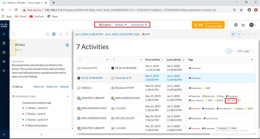
Click on this activity and navigate to Flows as shown below.
Figure 33 Total Flows for T104
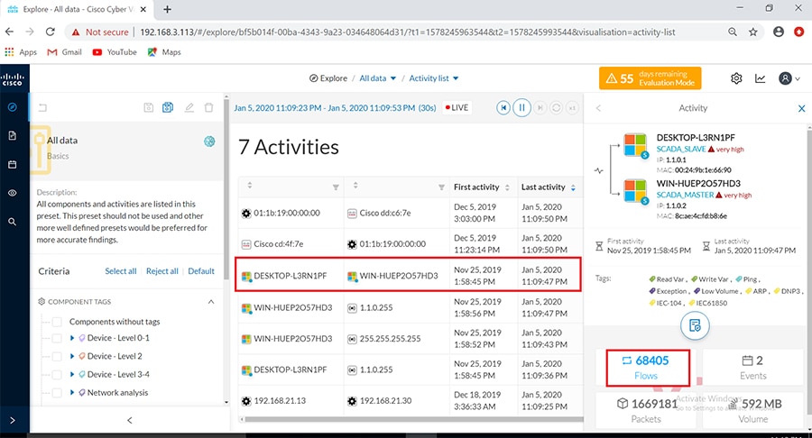
Under the activity selected, look on the Flows tab for the sub-tab tags and filter for IEC-104 traffic as shown below.
Figure 34 Filter tags for T104
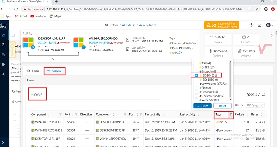
After the filter is applied, look for the T104 flows with the name IEC-104 which include the operations performed by the master on the slave as shown below.
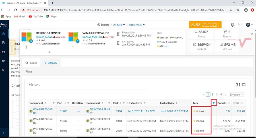
Click on the flows listed for IEC-104 one at a time to view more details about the flow properties. Look at the sub-tabs such as Properties or Content statistics to obtain more information on the operations performed. To obtain deeper visibility into the variables accessed for each operation, click on the component SCADA slave (DESKTOP-L3RN1PF) in the Activity panel on top of the Flows window as shown below. Next click on the Technical sheet for this component.
Figure 36 Technical sheet for IEC-104
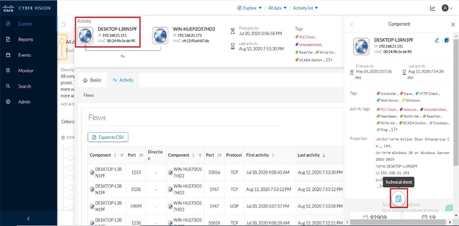
Next click on the Automation tab and under the column displayed for protocol, filter for IEC104 information as shown.
Figure 37 Filter for IEC104 variables under Automation tab
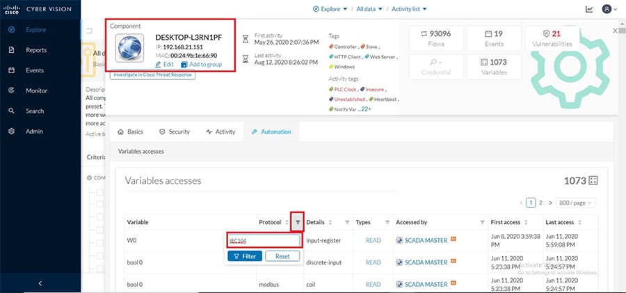
This would display information on the different variables accessed for each IEC104 operation performed as shown below. While Read and Write operations are indicated as is, Unsolicited operations are indicated as NOTIFY under the Variable Types column.
Figure 38 Variables Accessed for IEC104
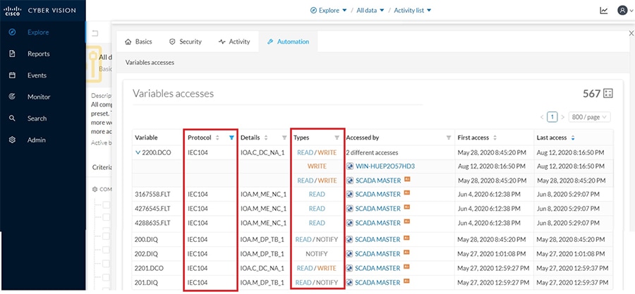
DNP3
After the network data begins to display in CVC, selectively filter the flows detected by the system for SCADA protocol. For example, DNP3 to view all the associated events, flows along with their tags as shown below.
Ensure reachability exists between SCADA Front End Processor or Controller and SCADA Outstation or IED systems and they are exchanging DNP3 traffic, specifically a Read (poll), Write (control) and Unsolicited reporting operations. Follow the steps below to view these events in CVC.
1.![]() Login to the CVC and navigate to All data > Activity list under Explore tab. Look for the tags associated with DNP3 and identify the activity of the associated SCADA systems exchanging DNP3 traffic as shown below.
Login to the CVC and navigate to All data > Activity list under Explore tab. Look for the tags associated with DNP3 and identify the activity of the associated SCADA systems exchanging DNP3 traffic as shown below.
Figure 39 Activity list for DNP3
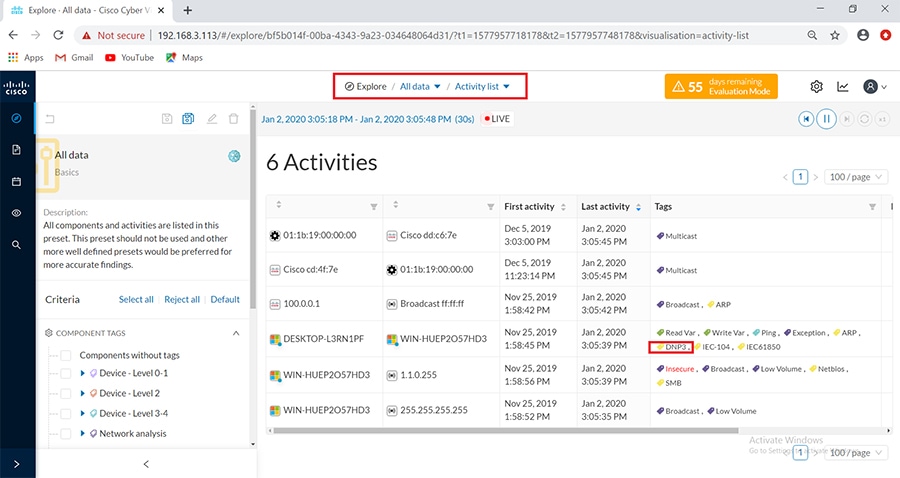
2.![]() The figure above shows both the SCADA Front End Processor or Controller primary (WIN-HUEP2O57HD3) and SCADA IED subordinate systems (DESKTOP-L3RN1PF). The first and last activity when they exchanged DNP3 messages is also shown. Click on this activity and navigate to Flows as shown below.
The figure above shows both the SCADA Front End Processor or Controller primary (WIN-HUEP2O57HD3) and SCADA IED subordinate systems (DESKTOP-L3RN1PF). The first and last activity when they exchanged DNP3 messages is also shown. Click on this activity and navigate to Flows as shown below.
Figure 40 Total Flows for DNP3
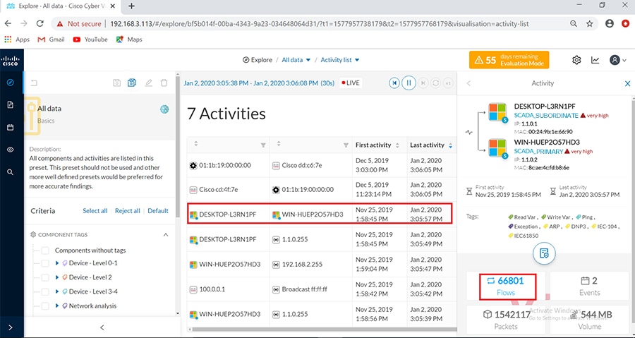
3.![]() Under the activity selected, open the Flows tab. Look for the sub-tab Tags and filter for DNP3 traffic as shown below.
Under the activity selected, open the Flows tab. Look for the sub-tab Tags and filter for DNP3 traffic as shown below.
Figure 41 Filter tags for DNP3
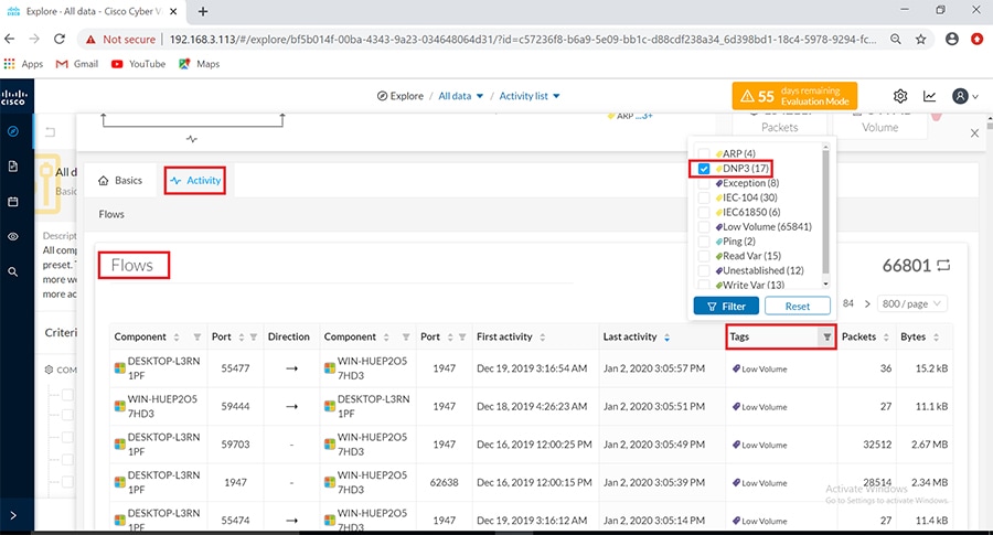
4.![]() After the filter is applied, notice the DNP3 flows showing Read and Write operations performed by the SCADA SCADA Front End Processor or Controller primary on the SCADA IED subordinate system as shown below.
After the filter is applied, notice the DNP3 flows showing Read and Write operations performed by the SCADA SCADA Front End Processor or Controller primary on the SCADA IED subordinate system as shown below.
Figure 42 Read, Write exchanges in DNP3
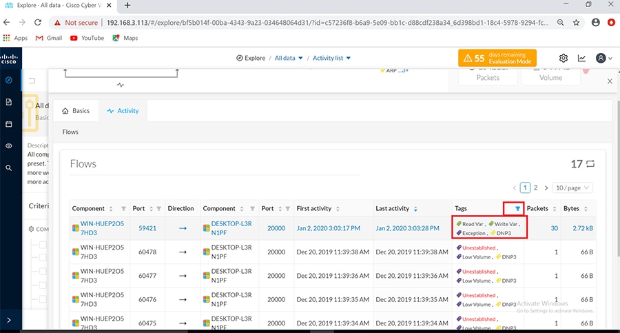
5.![]() Click on the flow highlighted in above figure to show more details about the flow Properties for the DNP3 operations performed as shown below.
Click on the flow highlighted in above figure to show more details about the flow Properties for the DNP3 operations performed as shown below.
Figure 43 Flow properties in DNP3
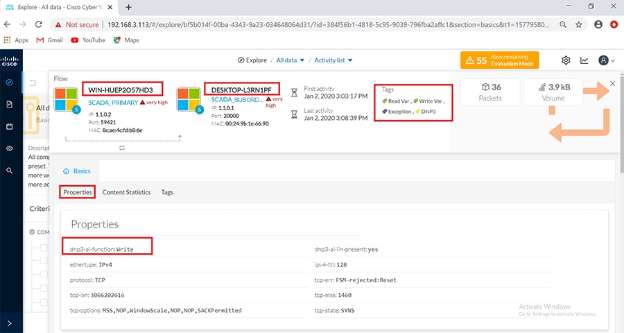
6.![]() On the Basics tab, the Content Statistics sub-tab shows the different DNP3 operations performed by the SCADA primary on the subordinate system.
On the Basics tab, the Content Statistics sub-tab shows the different DNP3 operations performed by the SCADA primary on the subordinate system.
Figure 44 Flow Content Statistics for DNP3
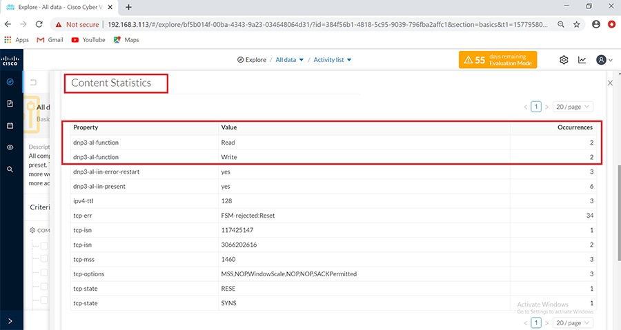
To view Unsolicited operations and the different variables accessed for each DNP3 operation, click on the component SCADA slave (DESKTOP-L3RN1PF) in the Activity panel on top of the Flows window as shown below. Next click on the Technical sheet for this component.
Figure 45 Technical sheet for DNP3
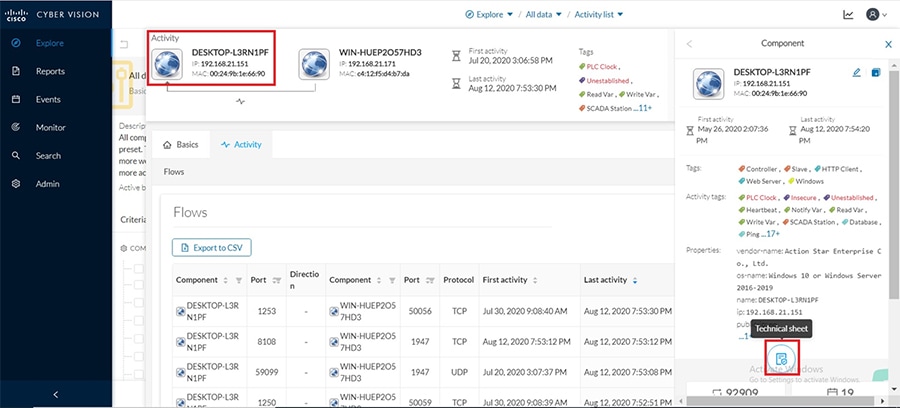
Next click on the Automation tab and under the column displayed for protocol, filter for DNP3 information as shown.
Figure 46 Filter for DNP3 variables under Automation tab
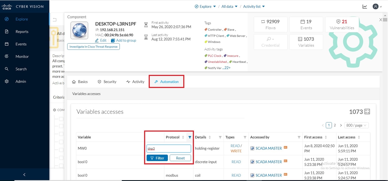
This would display information on the different variables accessed for each DNP3 operation performed as shown below. While Read and Write operations are indicated as is, Unsolicited operations are indicated as NOTIFY under the Variable Types column.
Figure 47 Variables Accessed for DNP3
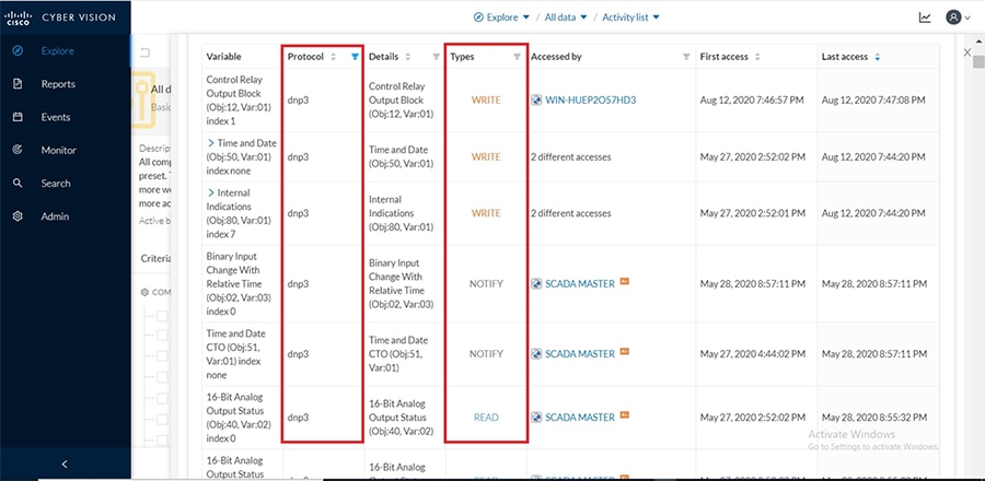
IEC61850 MMS and GOOSE
Ensure reachability exists between SCADA primary and subordinate systems and they are exchanging IEC-61850 MMS traffic between them. Specifically issue a Read (poll) and Write (control) operation from primary to subordinate and view these events in the CVC as shown below.
Log in to the CVC and navigate to All Data > Activity list under the Explore tab. Filter the list of activities displayed for MMS as shown below.
Figure 48 Activity list for MMS
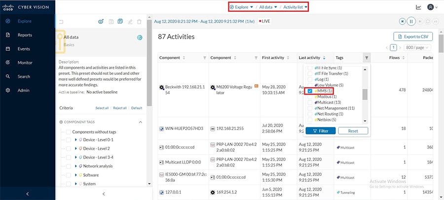
The filtered activity shows the SCADA primary (WIN-HUEP2O57HD3) and subordinate system components (DESKTOP-L3RN1PF) along with the first and last activity of their MMS messages exchanged. Click on this activity and navigate to Flows as shown below.
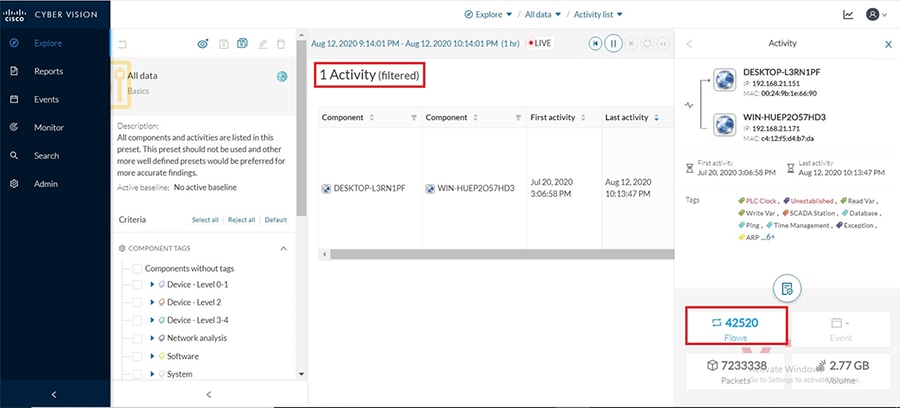
Under the listed flows for the selected activity, notice the MMS flow showing both Read and Write operation tags as shown below.
Figure 50 Read, Write tags for MMS
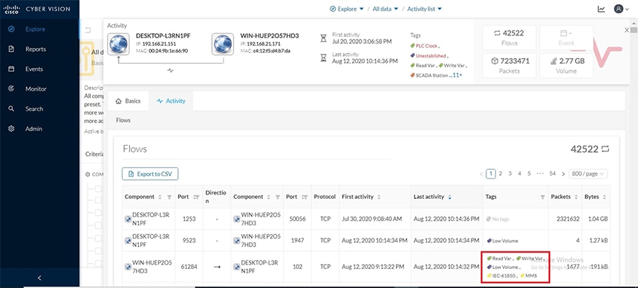
Once the filter is applied, look for the IEC-61850 flows. These include the operations performed by the primary on the subordinate as shown below.
Figure 51 Flow properties in MMS
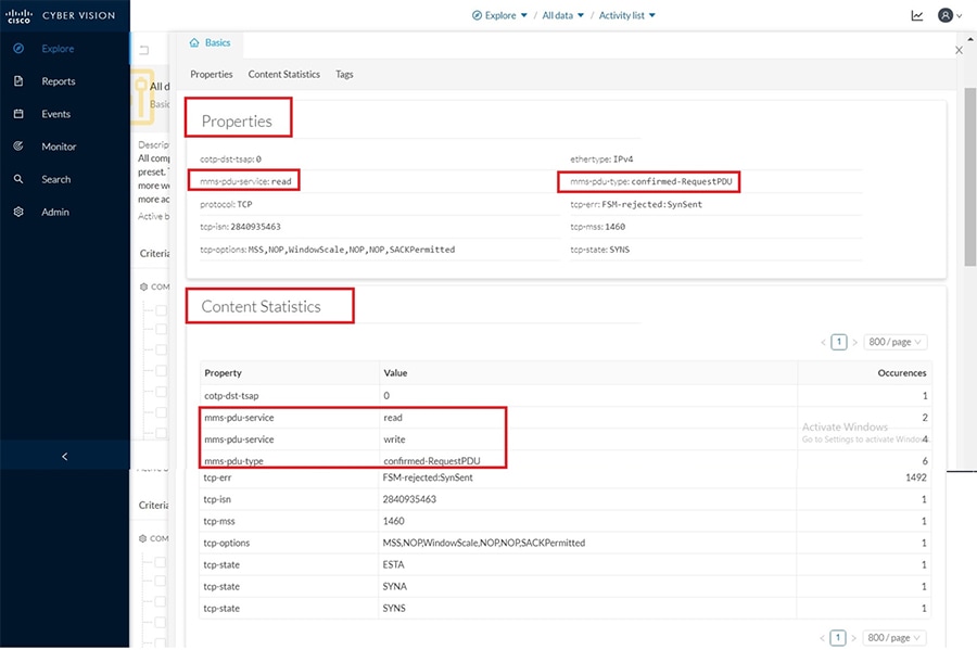
Notice that the Content Statistics sub-tab shows the different MMS operations performed by the SCADA primary on the subordinate system.
To view the different variables accessed for each MMS operation, click on the component SCADA subordinate (DESKTOP-L3RN1PF) in the Activity panel on top of the Flows window as shown below. Next click on the Technical sheet for this component.
Figure 52 Technical sheet for MMS
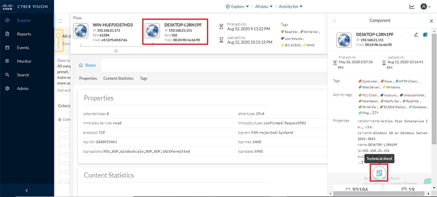
Next click on the Automation tab and under the column displayed for protocol, filter for MMS information as shown.
Figure 53 Filter for MMS variables under the Automation tab
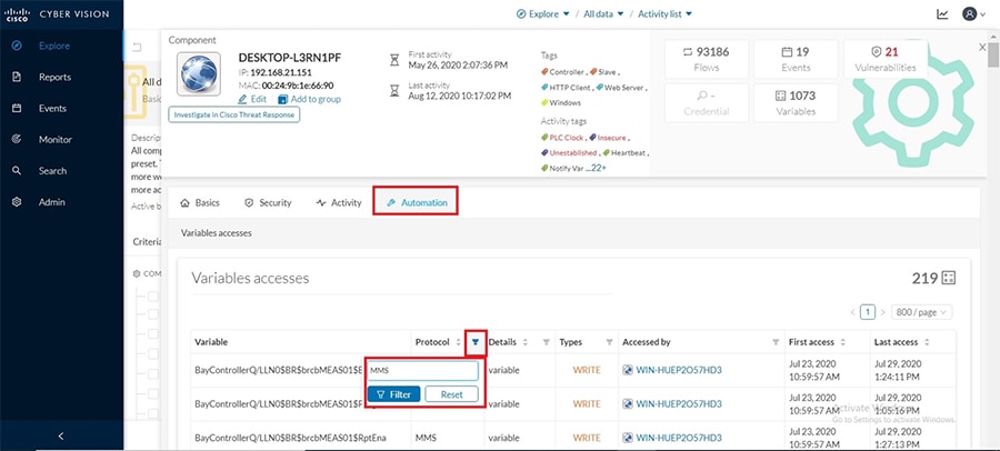
This would display information on the different variables accessed along with the type of MMS operations performed as shown below.
Figure 54 Variables Accessed for MMS
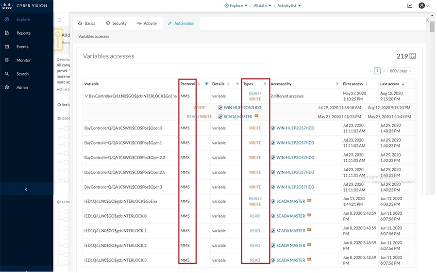
Repeat the same steps as above but instead filter for GOOSE and notice the flows, tags and variables accessed as shown below for reference.
Figure 55 GOOSE activity/flows
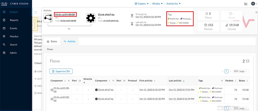
Figure 56 GOOSE variables accessed
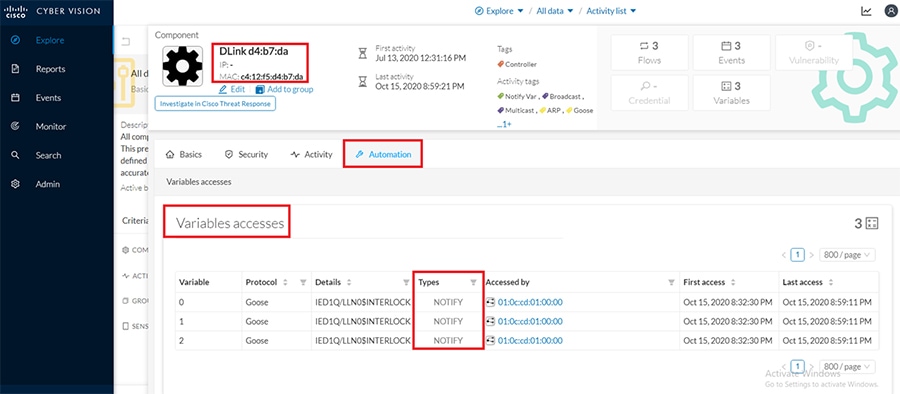
Modbus
This section focuses on the capability of the sensor and CVC to detect real controller/IED devices connected to the network along with the associated flows exchanged between the IED and the SCADA primary system running the control software to manage the IED. Below shown is the sample switch configuration needed to inter-connect an IED (for example a Beckwith controller) with the IC3000 hosting sensor application and thereafter enabling SPAN for detection of this device and its flows by CVC.
Once the switch SPAN configuration and the connectivity is completed as shown above, verify reachability exists between the IED device and its SCADA primary system. Then execute some read, write operations on the IED from the SCADA system so those flows can be detected by CVC as shown in detail below.
First login to the CVC and navigate to All data > Activity list under the Explore tab. Look for the tags associated with Modbus by filtering for the same as shown below.
Figure 57 Filter tags for Modbus
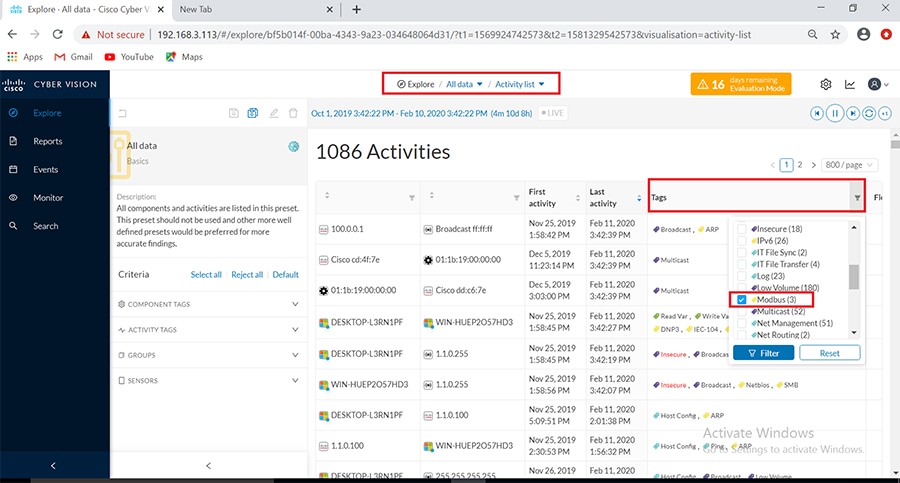
The above step provides all the activity of the associated systems exchanging Modbus traffic, specifically the IED (Beckwith controller) and the SCADA primary system (identified as ADMIN-PC) as shown below.
Figure 58 Activity list for Modbus
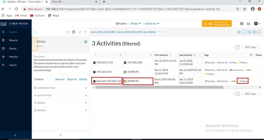
Next click on this activity and navigate to Flows as shown below.
Figure 59 Total Flows for Modbus
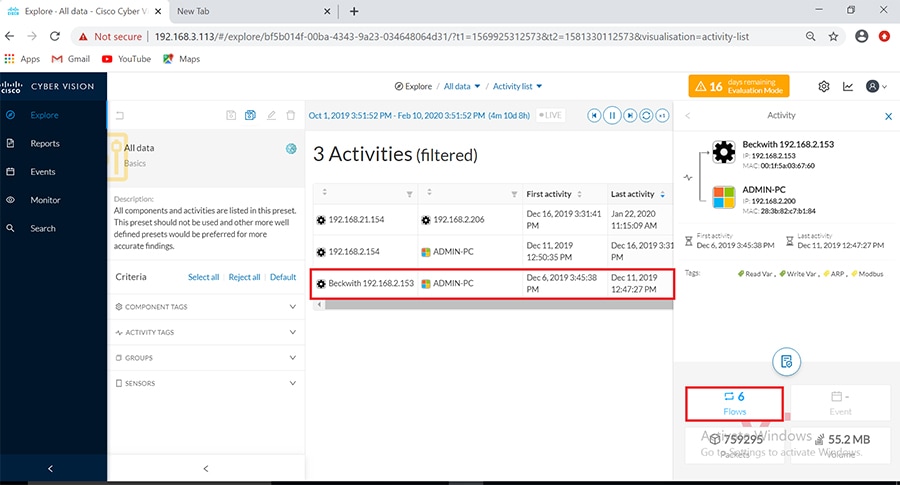
Notice all the Modbus related flows showing both Read and Write operation tags for the controller device as shown below.
Figure 60 Modbus flow exchanges
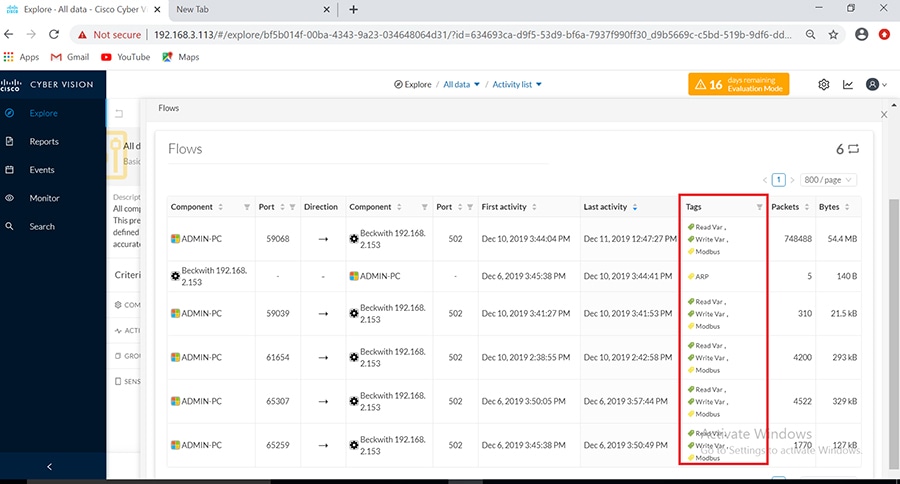
Clicking on any of the flows highlighted in above figure would show more details about the Flow Properties for the Modbus operations performed as shown below.
Figure 61 Flow properties in Modbus
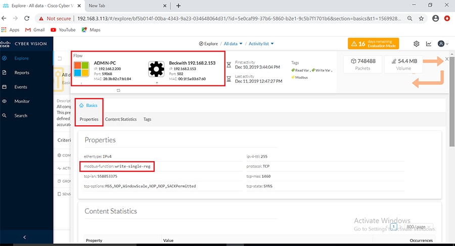
Additionally, under the Basics tab the Content Statistics sub-tab also shows more details about the Modbus operations performed on the controller.
Figure 62 Flow Content Statistics for Modbus
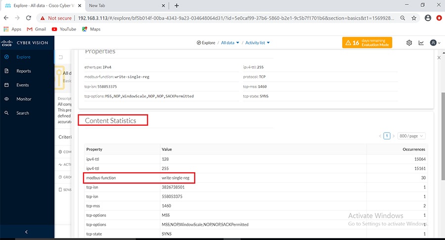
To view the different variables accessed for each Modbus operation, click on the component SCADA subordinate (DESKTOP-L3RN1PF) in the Activity panel on top of the Flows window as shown below. Next click on the Technical sheet for this component.
Figure 63 Technical sheet for Modbus
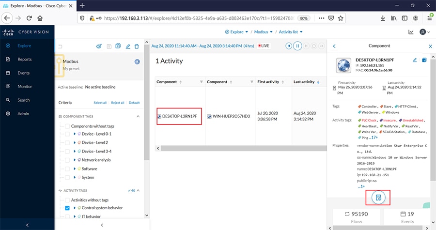
This would display information on the different variables accessed along with the type of Modbus operations performed as shown below..
Figure 64 Variables Accessed for Modbus
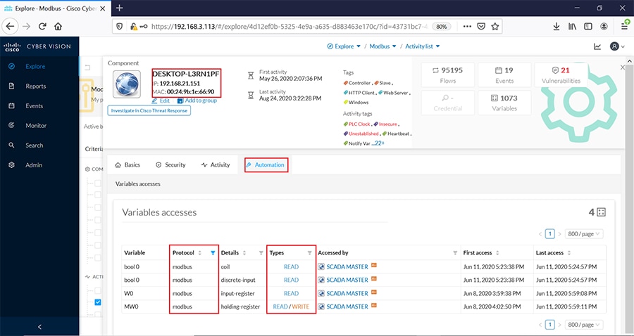
CVC includes an easy way to discover details about any connected IEDs in the network. Login to the CVC GUI and navigate to the Search tab on the left. Enter the IP address of a connected IED in the Asset Search field to display more details as shown below.
Legacy SCADA
Legacy SCADA is the way of transporting the stream of characters from one serial to another in the utility applications. This section describes how Cisco IR1101 is used to transport the serial data via IP network.
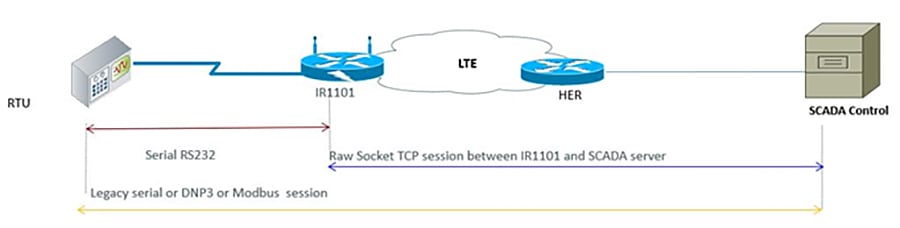
Raw Socket
Raw socket is a method of transporting serial data through an IP network. This feature can be used to transport SCADA data from Remote Terminal Units (RTUs). Raw Socket supports TCP or UDP as transport protocol. An interface can be configured anyone protocol but not both at the same time. This section shows the sample configuration for raw socket TCP on Cisco IR1101.
Serial interface configuration
Corresponding line configuration
In the above configuration IR1101 acts as a TCP server which listens on port 25000 (Port numbers vary for Modbus) and local binding IP of 192.168.150.16
Cisco IR1101 supports transporting MODBUS serial over Raw Socket, but the Deep Packet Inspection of OT visibility is not supported in Cisco CyberVision Center. The same will be supported in future release. The configuration of raw-socket TCP on Cisco IR1101 is in the Raw Socket section.
Note: DDTS CSCvu86798 has been raised to track the feature support on Cisco CyberVision Center.
Cisco IR1101 supports transporting DNP3 serial over Raw Socket and the deep packet inspection of OT traffic can be seen in Cisco CyberVision Center. Refer to the of raw-socket configuration of TCP on the Cisco IR1101 in the Raw Socket section.
Figure 66 Activities List for Raw Socket DNP3
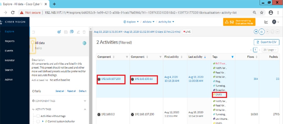
Next click on this activity and navigate to Flows as shown below.
Figure 67 Total Flows for DNP3
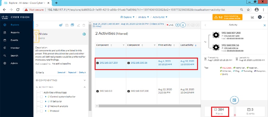
Figure 68 Flow Properties of Raw Socket DNP3
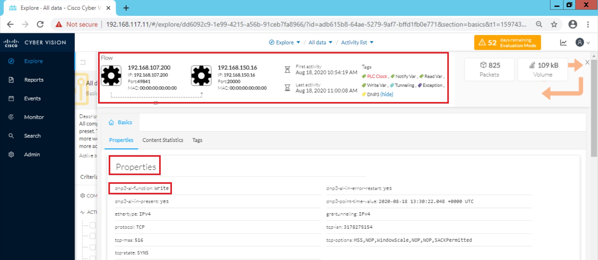
Figure 69 Flow Contents of Raw Socket DNP3
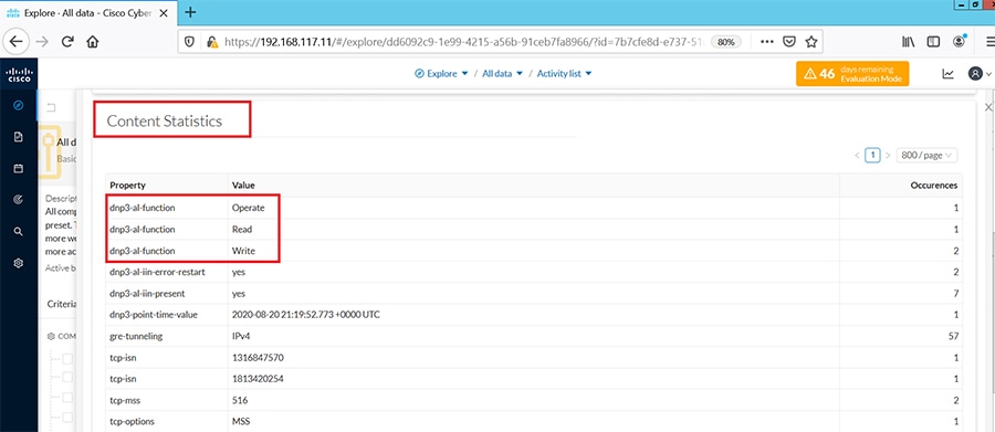
In the above figure, various operations performed such as read/write can be observed under Flow content statistics which can be viewed by selecting the SCADA FEP (192.168.107.200) and clicking on Flows.
Figure 70 Technical sheet for Raw Socket DNP3
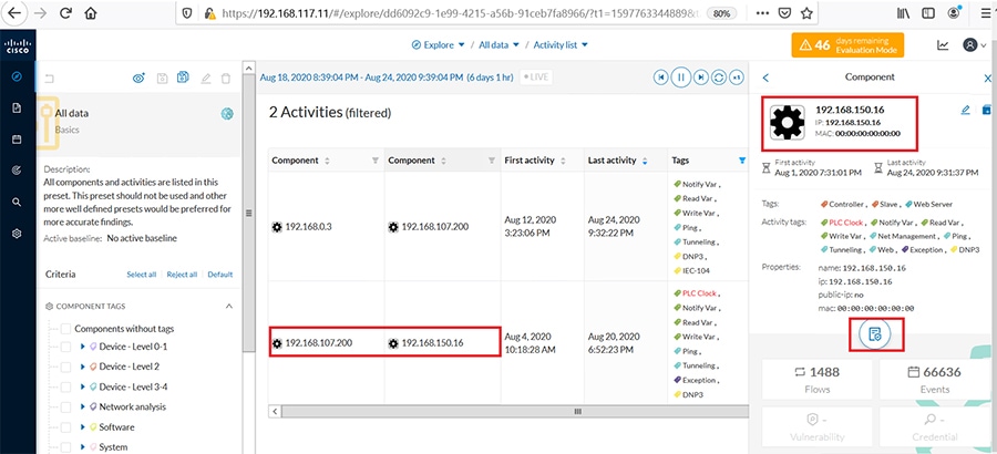
In the above figure, 192.168.150.16 is the Tunnel IP of IR1101 where the Raw-socket terminates. Select SCADA IEDs(192.168.150.16) and click on the Technical sheet to observe the variables accessed for DNP3 by SCADA FEP.
Figure 71 Variable Accessed for Raw Socket DNP3
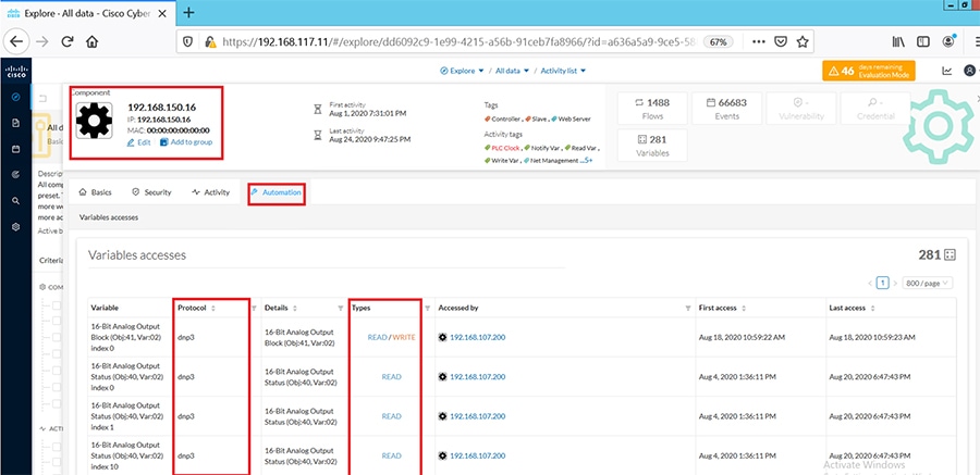
In the above figure, we can view the DNP3 variables accessed by SCADA FEP on IEDs.
Protocol Translation
In the network, the Control Center always serves as the master in the network when communicating with the IR1101. The IR1101 serves as a proxy master station for the Control Center when it communicates with the RTU.
The IR1101 provides protocol translation to serve as a SCADA gateway to do the following:
■![]() Receive data from RTUs and relay configuration commands from the Control Center to RTUs.
Receive data from RTUs and relay configuration commands from the Control Center to RTUs.
■![]() Receive configuration commands from the Control Center and relay RTU data to the Control Center.
Receive configuration commands from the Control Center and relay RTU data to the Control Center.
■![]() Terminate incoming requests from the Control Center, when an RTU is offline.
Terminate incoming requests from the Control Center, when an RTU is offline.
The IR1101 performs Protocol Translation for the following protocols:
T101/T104 Protocol Translation
In this scenario, the RTU is connected to the Cisco IR1101 via the serial or Ethernet port, then the SCADA control and the RTU can communicate via Cisco IR1101 as the SCADA gateway. The communication between the RTU and SCADA control station can be Ethernet based (T104) or RS232 serial communication (T101) or by means of protocol translation. For each of these operations being performed, refer to the Flow diagram showing T104/T101 control flow in the DA Secondary Substation Implementation Guide available at the below location.
https://www.cisco.com/c/en/us/td/docs/solutions/Verticals/Distributed-Automation/Secondary-Substation/IG/DA-SS-IG/DA-SS-IG-doc.html#pgfId-296649
IR1101 SCADA Gateway Configuration
SCADA Gateway for T101/T104 configuration:
Once the above configurations are made on IR1101, it acts as a SCADA-GW for translating the T101 to/From T104. In the above case T104 is the SCADA FEP and T101 is the SCADA RTU.
Figure 72 Activity list and Total Flows for Protocol Translation
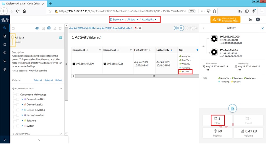
Log in to the CVC and navigate to All Data > Activity list under the Explore tab. Look for the tags associated with IEC-104 and identify the activity of the associated systems exchanging T104 traffic as shown below.
Click on this activity and navigate to Flows as shown below.
Figure 73 Tags and Flow Exchanges for Protocol Translation
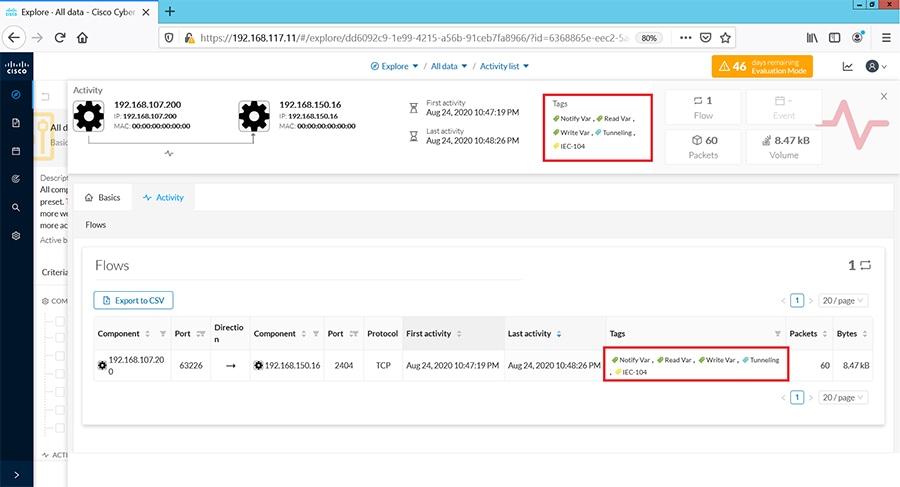
Under the activity selected, filter the tags for IEC104 and view the flow exchanges and tags applied for protocol translation.
Click on the flows listed for IEC-104 one at a time to view more details about the flow properties. Look at the sub-tabs such as Properties or Content statistics to obtain more information on the operations performed. To obtain deeper visibility into the variables accessed for each operation, click on the component SCADA RTU (192.168.150.16) in the Activity panel on top of the Flows window as shown below. Next click on the Technical sheet for this component.
Figure 74 Technical Sheet for Protocol Translation
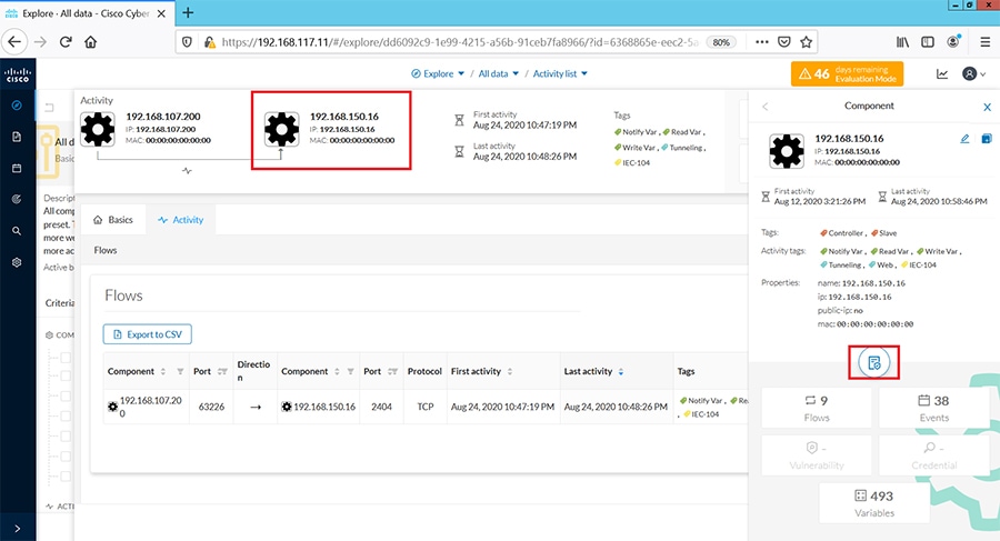
Next click on Automation tab and under the column displayed for protocol, filter for IEC104 information.
Figure 75 Variables Accessed for Protocol Translation
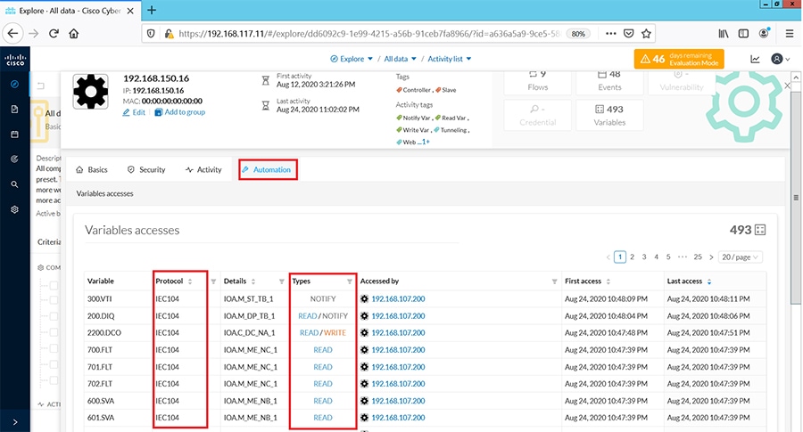
This would display information on the different variables accessed for each IEC104 operation performed as shown above. While Read and Write operations are indicated as is, Unsolicited operations are indicated as NOTIFY under the Variable Types column.
OT Assets Anomaly Detection-Monitoring
To detect changes within industrial networks, CVC provides a monitoring tool called Monitor mode which shows changes in network states from the baselines. Changes, either normal or abnormal, are noted when differences are found between a baseline and a comparison point. Comparisons that have been performed are reported in the Events pages. Events generated by CVC are used to identify and keep track of significant activities in the network like an activity, a property, or a change pertaining to hardware or software components.
In monitor mode, you will create an initial baseline which is a snapshot of the network state considered normal at a defined time of an outstation component and its controller or SCADA Front End Processor. The next step is to make a network change such as a flow trying to access a component or trying to modify variables and check if CVC detects this change and reports it as an event.
Follow the steps below for this example.
1.![]() Create a preset named Test_Preset as shown in the following figure.
Create a preset named Test_Preset as shown in the following figure.
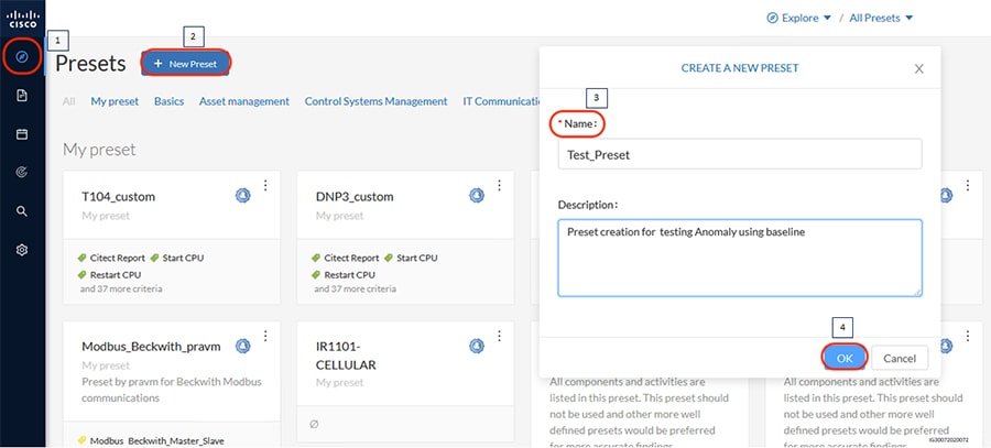
2.![]() Select the created preset and check if the desired data like components, related activities, etc. are reflected as highlighted.
Select the created preset and check if the desired data like components, related activities, etc. are reflected as highlighted.
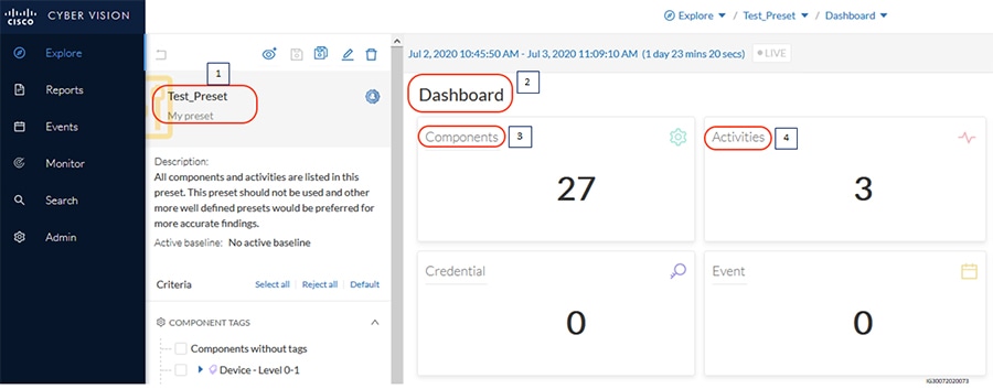
3.![]() Create a baseline named ‘Modbus_New_Baseline_For_ReadOperation’ as shown in the following figure and click on Create. Ensure that the period for which baseline needs to be created is selected appropriately. It can be ensured by setting the time period in the preset created.
Create a baseline named ‘Modbus_New_Baseline_For_ReadOperation’ as shown in the following figure and click on Create. Ensure that the period for which baseline needs to be created is selected appropriately. It can be ensured by setting the time period in the preset created.
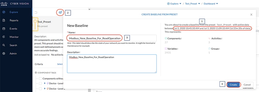
4.![]() Once the baseline is created, the network map, the list of various components, activities, and variables in the network can be detected as highlighted in the following figure.
Once the baseline is created, the network map, the list of various components, activities, and variables in the network can be detected as highlighted in the following figure.
Figure 79 Viewing Baseline details
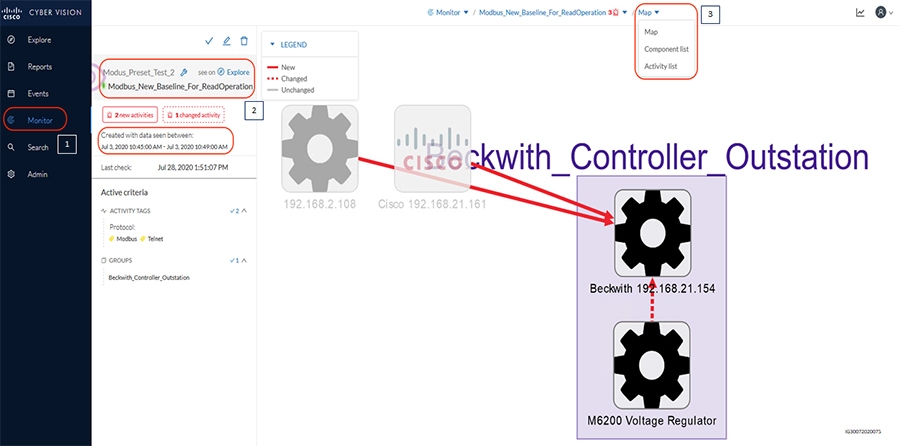
5.![]() As described earlier, try to establish a connection to the outstation from different devices and also try to modify variables that are not part of the baseline. CVC should detect the changes as highlighted in the following figure.
As described earlier, try to establish a connection to the outstation from different devices and also try to modify variables that are not part of the baseline. CVC should detect the changes as highlighted in the following figure.
Figure 80 CVC Detecting Changes in Baseline
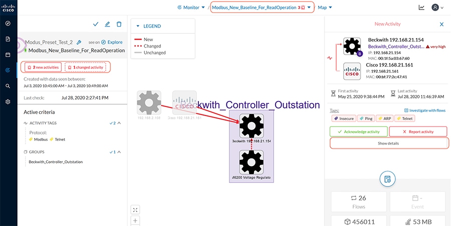
6.![]() The CVC provides an option to either acknowledge the activity and approve or report the activity for further analysis and remediation if required. The following snapshot shows the steps to report the activity as an Anomaly.
The CVC provides an option to either acknowledge the activity and approve or report the activity for further analysis and remediation if required. The following snapshot shows the steps to report the activity as an Anomaly.
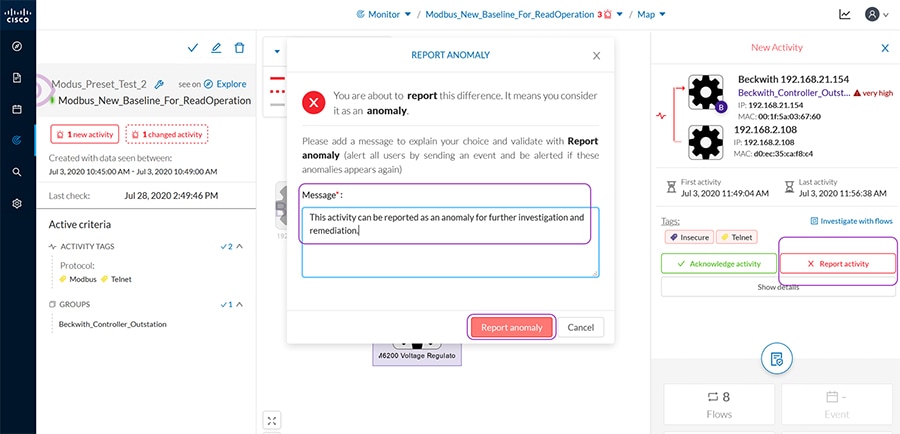
7.![]() CVC provides a separate category of events for Anomaly detection. To view these events, navigate to the Events page in the CVC GUI and search for Anomaly as shown below. The Anomaly events can also be sent to syslog servers with appropriate configuration. Click on the event to view more details about the new activity in the network as shown below. Notice that this is the same information seen from the Monitor mode page on doing a comparison with the baseline.
CVC provides a separate category of events for Anomaly detection. To view these events, navigate to the Events page in the CVC GUI and search for Anomaly as shown below. The Anomaly events can also be sent to syslog servers with appropriate configuration. Click on the event to view more details about the new activity in the network as shown below. Notice that this is the same information seen from the Monitor mode page on doing a comparison with the baseline.
Figure 82 View Anomaly Detection Events
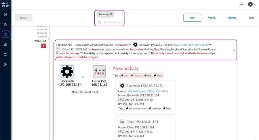
Refer to the following guide for more details and options that are available to configure baseline for detecting anomalies.
https://www.cisco.com/c/dam/en/us/td/docs/security/cyber_vision/Cisco_Cyber_Vision_GUI_User_Guide_Release_3_1_0.pdf
Threat Detection
SCADA Modbus Preprocessor on ISA3000
Cisco ISA3000 Application identification goes beyond traditional port numbers and inspecting the entire frame to recognize the protocol/application. Most of the Industrial Firewalls in the market recognize protocols/applications using the port numbers. Using just the port numbers leads to misidentification when protocols are overloaded on the same port numbers.
In this scenario, you will explore the OT Application identification supported on Cisco ISA3000. This allows you to see the OT protocols supported on Cisco ISA3000. You can experiment with creating rules to control OT traffic. An example of this is to allow Modbus TCP traffic and deny other protocols.
For details on the list of different OT protocols supported on ISA3000 refer to the following link. https://www.cisco.com/c/en/us/products/collateral/security/industrial-security-appliance-3000/data-sheet-c78-735839.pdf
Summary
Navigate to FMC > Policies > Access Control as highlighted in the following figure. Click Access Control.
Figure 83 SCADA Preprocessor Creating New Access Control Policy
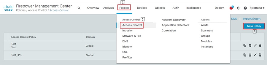
Enter access policy details like name, default action, and the device on which the policy should be applied as highlighted in the following figure.
Figure 84 SCADA Preprocessor New Access Control Policy properties
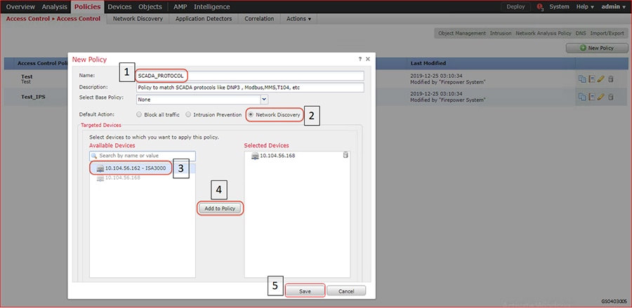
Click Add Rule, and then select zones as highlighted in the following figure.
Figure 85 SCADA Preprocessor Adding New Rule to the New Access Control Policy
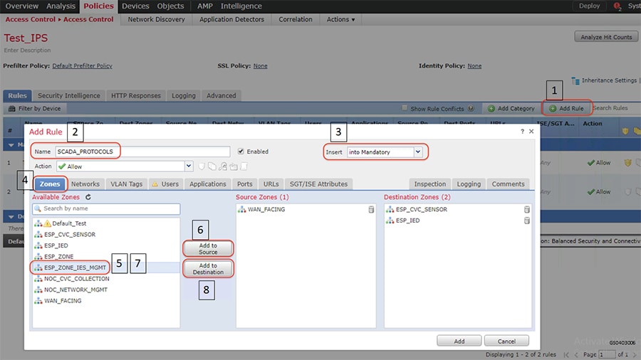
Click the Applications tab and select protocols of interest as highlighted in the following figure.
Figure 86 SCADA Preprocessor Selecting Applications for the New Rule
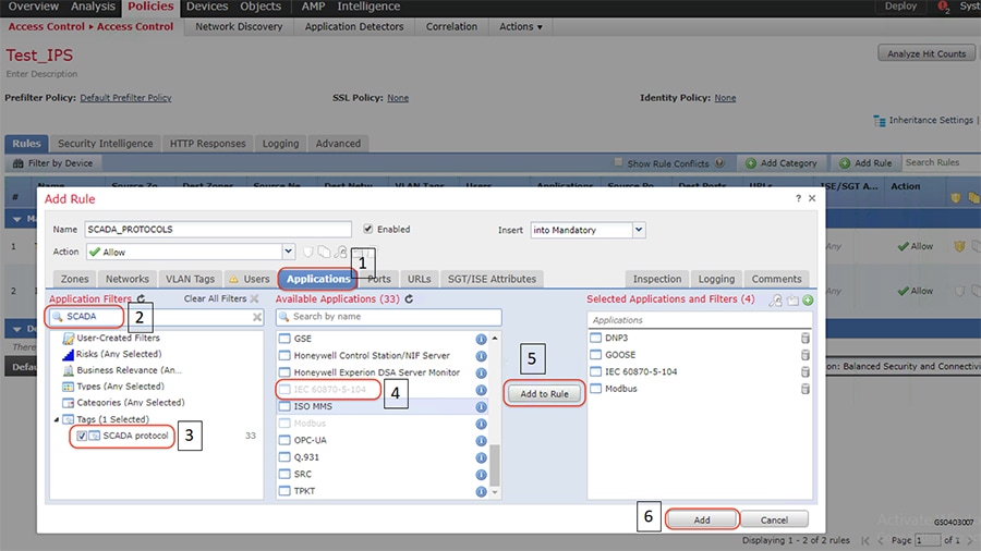
Enable logging by following the steps highlighted in the following figure.
Figure 87 SCADA Preprocessor Enabling Logging for the New Rule
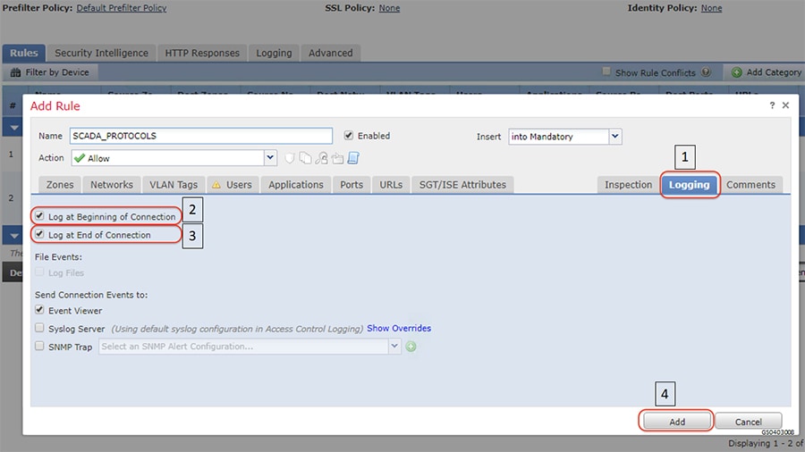
After the rule is added, click the Advanced tab and proceed as highlighted in the following figure. Click Network Analysis Policy List to open the next window.
Figure 88 SCADA Preprocessor Network Analysis Policy
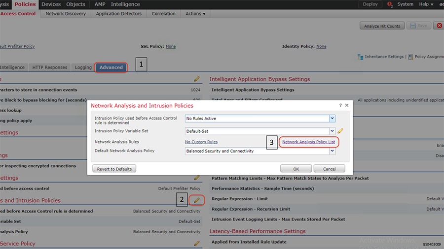
Click the Create Policy button and follow the steps as highlighted in the following figure.
Figure 89 SCADA Preprocessor Creating new Network Analysis Policy
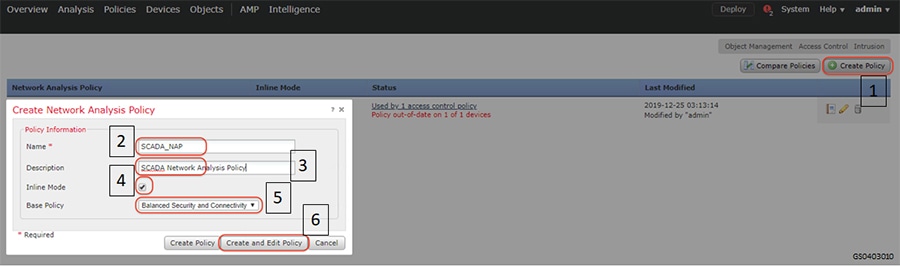
Click My Changes option listed under Policy Layers on the left hand side of the resulting window and follow the steps as highlighted in the following figure.
Figure 90 SCADA Preprocessor Editing Network Analysis Policy
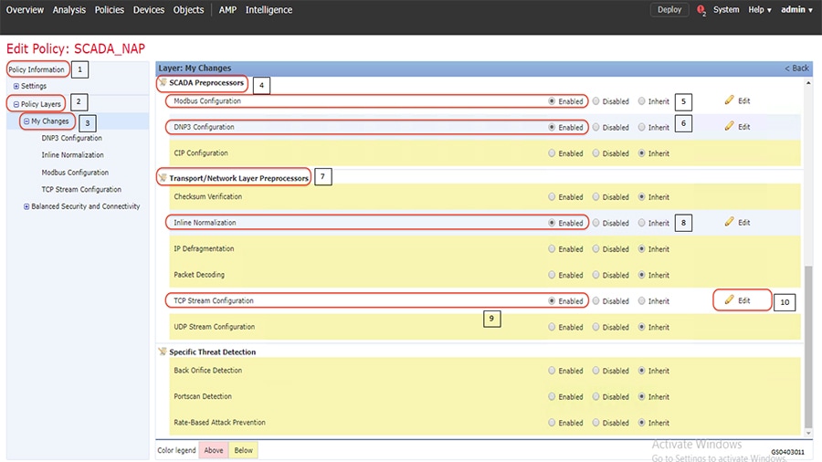
Clicking the Edit button across TCP Stream Configuration as highlighted by number 10 in the previous figure, results in a new window. Scroll down to “Perform Stream Reassembly on Both Ports” settings and add ports 502 for Modbus and 2000 for DNP3. Click Back after modifications. Refer to highlights in the following figure.
Figure 91 Preprocessor Adding Protocol properties
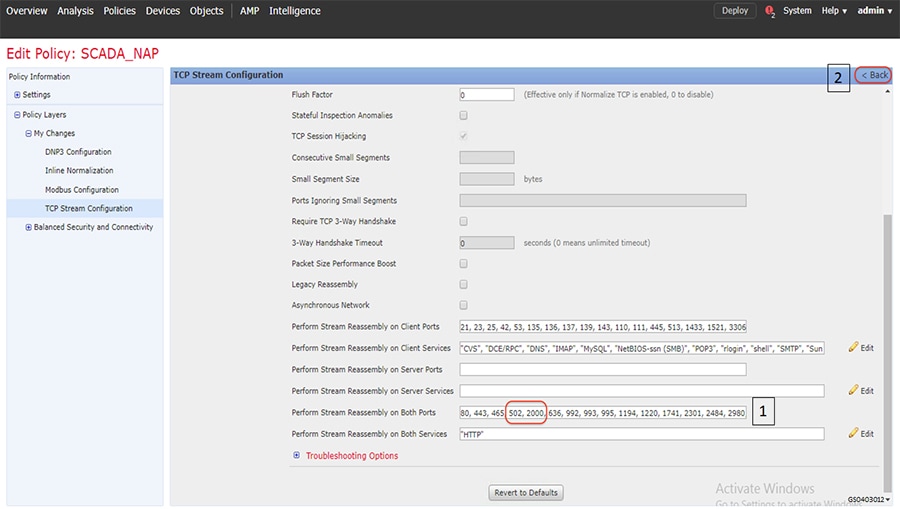
Click Back in the resulting window.
Click Commit Changes and proceed as highlighted in the following figure. The resulting window lists the newly-created policy.
Figure 92 SCADA Preprocessor Commit new Network Analysis Policy
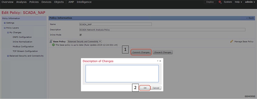
Navigate to the original window shown in Step 6 above.
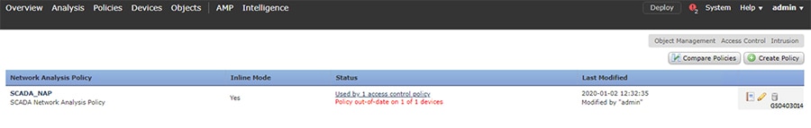
Click Create Policy button and follow the steps as highlighted in the following figure. The newly-created policy is listed in the drop down list for Default Network Analysis Policy. Select the appropriate policy and click OK. Save the policy by clicking Save button.
Figure 93 SCADA Preprocessor selecting new Network Analysis Policy
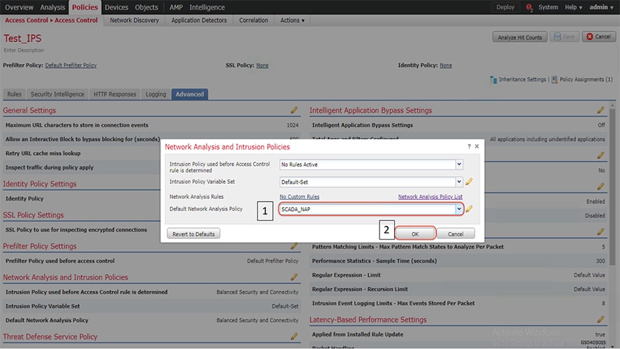
Deploy the policy on the intended device as highlighted in the following figure.
Figure 94 SCADA Preprocessor Deploying new Policy Verification
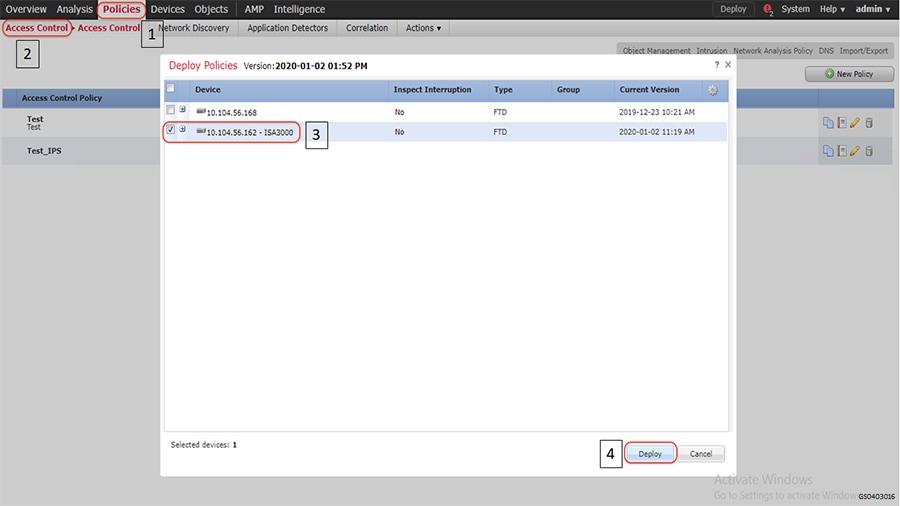
Initiate traffic and check if the applied policy classifies and identifies the type of application and the protocol it uses. This scenario was validated with Modbus application and firewall policy applied on ISA3000 as highlighted in the following figure.
Figure 95 SCADA Preprocessor verifying newly created Network Analysis Policy
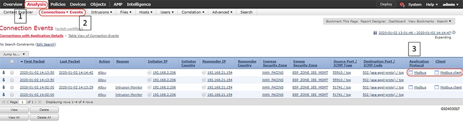
SCADA DNP3 Preprocessor on ISA3000
Cisco ISA3000 Application identification goes beyond traditional port numbers and inspecting the entire frame to recognize the protocol/application. Most of the Industrial Firewalls in the market recognize protocols/applications using the port numbers. Using just the port numbers leads to misidentification when protocols are overloaded on the same port numbers.
In this scenario, you will explore the OT Application identification supported on Cisco ISA3000. This allows you to see the OT protocols supported on Cisco ISA3000. You can experiment with creating rules to control OT traffic. An example of this is to allow DNP3 traffic and deny other protocols.
For details on the list of different OT protocols supported on ISA3000 refer to the following link. https://www.cisco.com/c/en/us/products/collateral/security/industrial-security-appliance-3000/data-sheet-c78-735 839.pdf
Summary
Navigate to FMC > Policies > Access Control as highlighted in the following figure. Click Access Control.
Figure 96 SCADA Preprocessor Creating New Access Control Policy
Enter access policy details like Name, default action and the device on which the policy should be applied as highlighted in the following figure.
Figure 97 SCADA Preprocessor New Access Control Policy properties
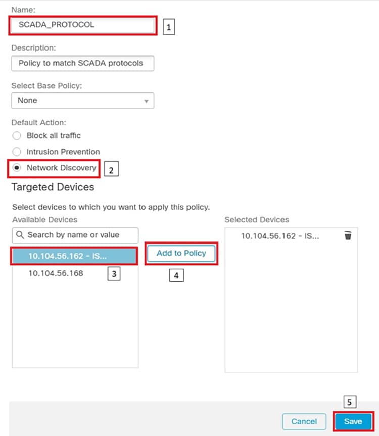
Click Add Rule, and then select zones as highlighted in the following figure.
Figure 98 SCADA Preprocessor Adding New Rule to the New Access Control Policy
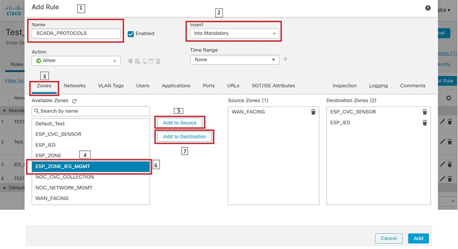
Click the Applications tab and select protocols of interest as highlighted in the following figure.
Figure 99 SCADA Preprocessor Selecting Applications for the New Rule
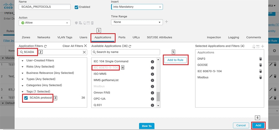
Enable logging by following the steps highlighted in the following figure.
Figure 100 SCADA Preprocessor Enabling Logging for the New Rule
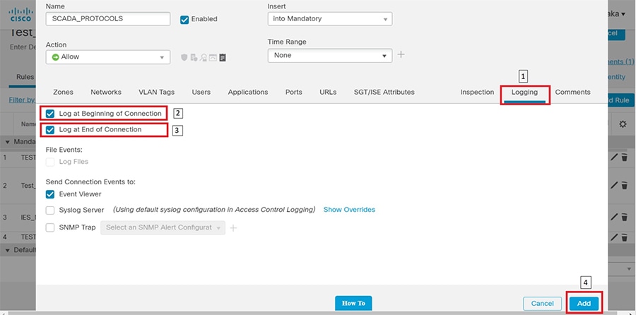
After the rule is added, click the Advanced tab and proceed as highlighted in the following figure. Click Network Analysis Policy List to open the next window.
Figure 101 SCADA Preprocessor Network Analysis Policy
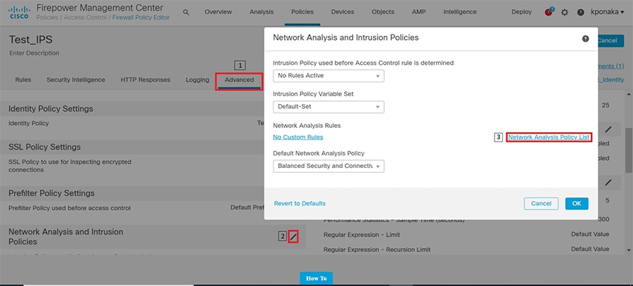
Click the Create Policy button and follow the steps as highlighted in the following figure.
Figure 102 SCADA Preprocessor Creating new Network Analysis Policy
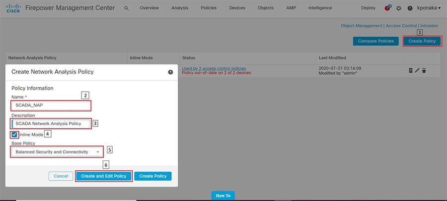
Click My Changes option listed under Policy Layers on the left-hand side of the resulting window and follow the steps as highlighted in the following figure.
Figure 103 SCADA Preprocessor Editing Network Analysis Policy
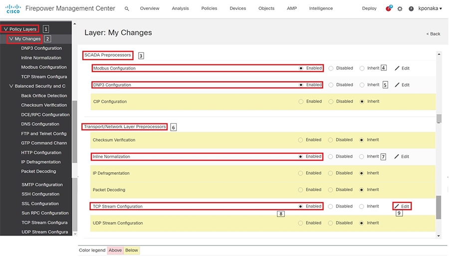
Clicking the Edit button across TCP Stream Configuration as highlighted by number 9 in the previous figure, results in a new window. Scroll down to “Perform Stream Reassembly on Both Ports” settings and add ports 502 for Modbus and 20000 for DNP3. Click Back after modifications. Refer to highlights in the following figure.
Figure 104 Preprocessor - Adding Protocol properties
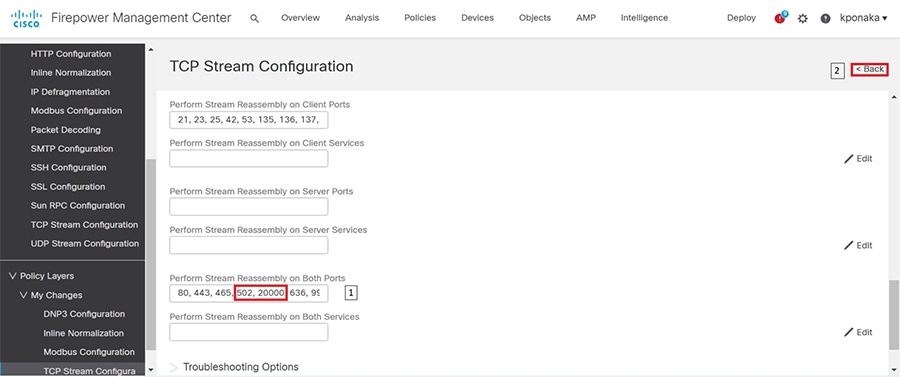
Click Commit Changes and proceed as highlighted in the following figure.
Figure 105 SCADA Preprocessor Commit new Network Analysis Policy
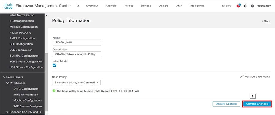
The resulting window lists the newly created policy.
Figure 106 SCADA Preprocessor new Network Analysis Policy
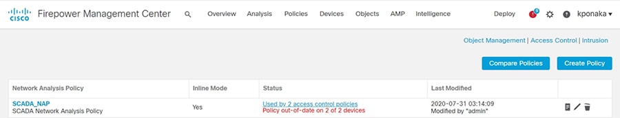
Next, navigate to the window shown in Figure 101 where a new Access control policy was created, and the newly created Network Analysis policy would be selected in the drop-down by following the steps highlighted in the following figure.
The newly created policy is listed in the drop-down list for Default Network Analysis Policy. Select the appropriate policy and click OK.
Save the policy by clicking Save button.
Figure 107 SCADA Preprocessor selecting new Network Analysis Policy
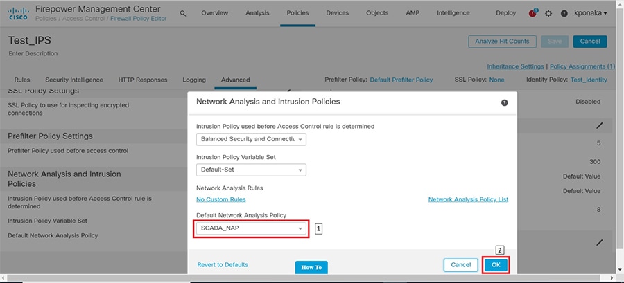
Deploy the policy on the intended device as highlighted in the following figure.
Figure 108 SCADA Preprocessor Deploying new Policy Verification
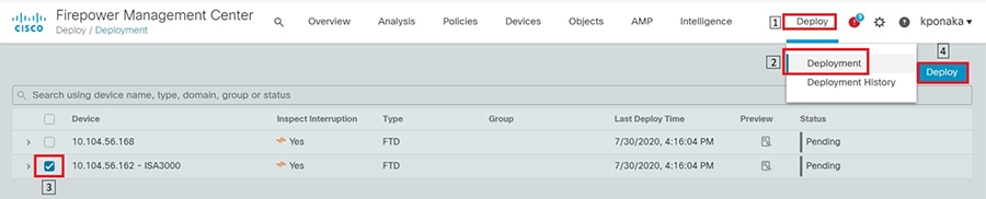
Initiate traffic and check if the applied policy classifies and identifies the type of application and the protocol it uses. This scenario was validated with DNP3 application and firewall policy applied on ISA3000 as highlighted in the following figure.
Figure 109 SCADA Preprocessor verifying newly created Network Analysis Policy
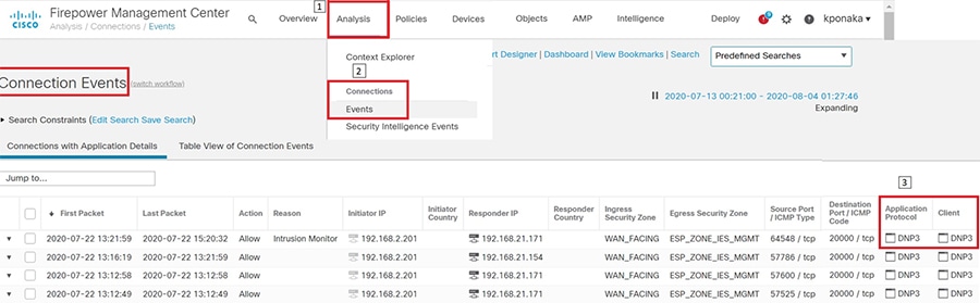
Deep Packet inspection of Modbus using ISA3000
This scenario demonstrates how Cisco ISA3000 can be used to detect individual commands in a SCADA application. This functionality is extremely helpful in OT networks to provide visibility into the transactions that happen between endpoints and detect malicious behavior that may be result of a malware infection or an attack on Industrial Infrastructure. In particular, we will create IPS Rules on ISA3000 to detect individual Modbus commands such as READ or WRITE and generate an event for the same.
For details on the list of different OT protocols supported on ISA3000 refer to the following link. https://www.cisco.com/c/en/us/products/collateral/security/industrial-security-appliance-3000/data-sheet-c78-735839.pdf
Summary
Navigate to FMC > Policies > Access Control and click Intrusion as highlighted in the following figure.
Figure 110 Navigation to create new intrusion policy
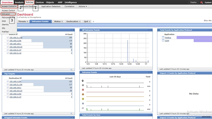
Click on Intrusion Rules as highlighted in the following figure.
Figure 111 Navigation to create new intrusion rule
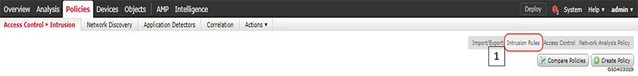
Click on Create Rule in the resulting page as highlighted in the following figure.
Figure 112 Create new intrusion rule
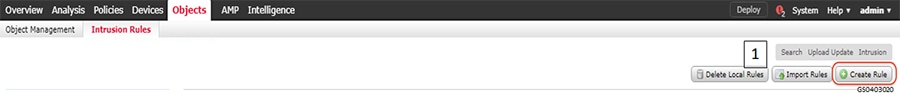
Fill in the details in the resulting page as highlighted in the following figure. As mentioned earlier, this scenario demonstrates Modbus Protocol command detection. The figure shows a rule being created for Modbus read coils command to Modbus Substation ID 1 (Modbus unit) and generate an alert for the same.
Figure 113 Defining intrusion rule properties
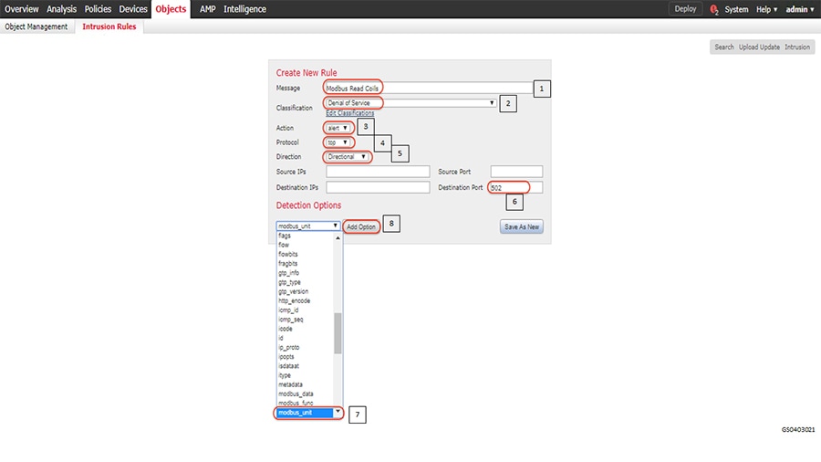
A Modbus will have a unit number often referred to as station ID. This example uses 1 for the emulated PLC.
Identify the command that needs to be inspected for as highlighted in the following figure. The figure shows Modbus Read Coils command.
Figure 114 Define modbus function to be inspected
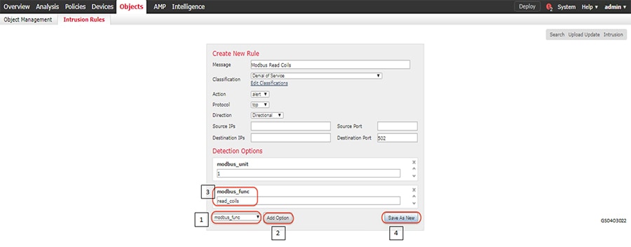
An IPS rule that can sort through all the traffic that gets sent across ISA3000 and find a Modbus flow that issues a Read Coils command to Modbus unit 1 has been created. This functionality opens up many possibilities for intrusion detection and enforcement. Once the rule is successfully added, we can add a few more rules by simply modifying the current rule and saving as new again. In our lab, we also created rules for Modbus commands viz. write_single_coil and write_multiple_coils.
Create a new Intrusion Policy with the newly created Intrusion rules as highlighted in the following figure.
Figure 115 Create new intrusion policy
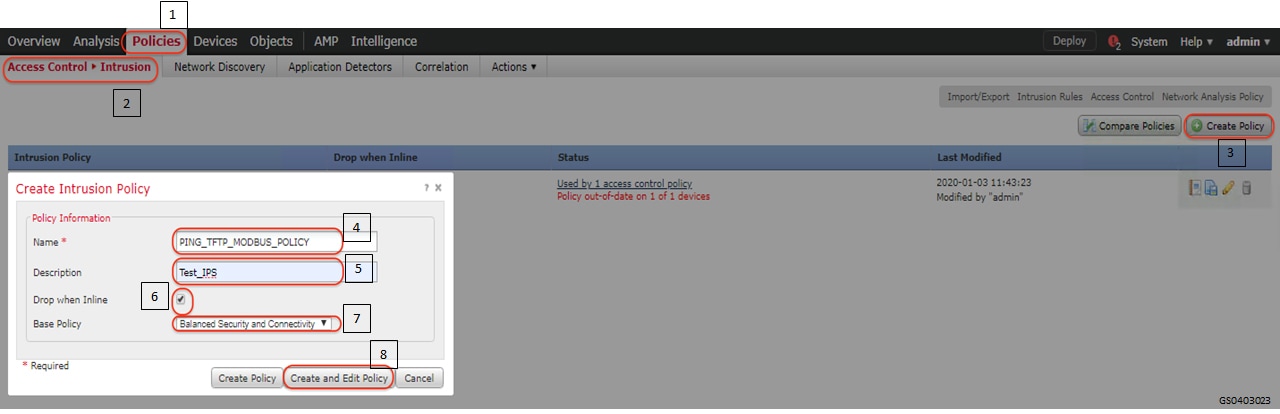
In the resulting edit policy window click rules and select the rules and corresponding actions for the rules as highlighted in the following figure.
It is recommended to not select Drop action especially in OT environments, where Availability has higher priority than Security. Giving visibility to the user in the form of events is important.
Figure 116 Add intrusion rules to intrusion policy
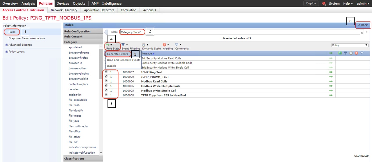
Commit the changes in the resulting window as highlighted in the following figure.
Figure 117 Commit changes to intrusion policy
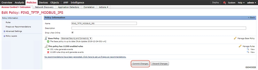
Create a new access control policy as highlighted in the following figure.
Figure 118 Create Access control policy for intrusion prevention
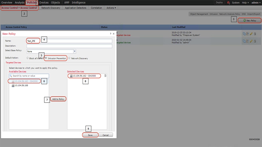
Add rule with the intended intrusion policy in the resulting window as highlighted in the following figure.
Figure 119 Attach intrusion policy to access control policy
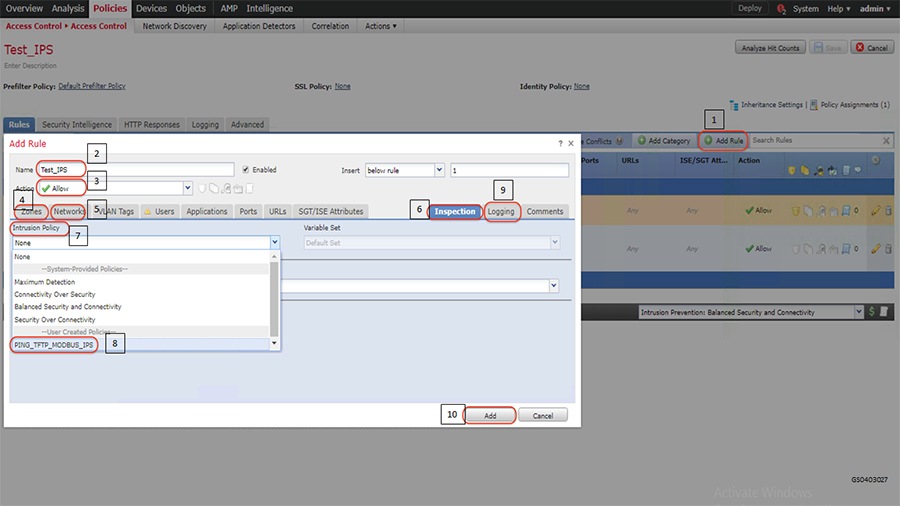
Save the newly added rule and deploy the policy onto Cisco ISA3000 as highlighted in the following figure.
Figure 120 Deploy newly created Access control policy for intrusion prevention
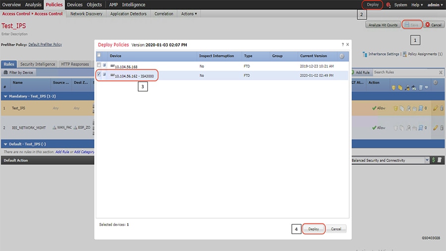
Verification
Initiate traffic and check if the applied policy classifies and identifies the type of application and the protocol it uses. This scenario was validated with Modbus application and firewall policy applied on ISA3000 and ensuring that required events gets generated as highlighted in the following figure.
Figure 121 Verifying newly created Access control policy for intrusion prevention
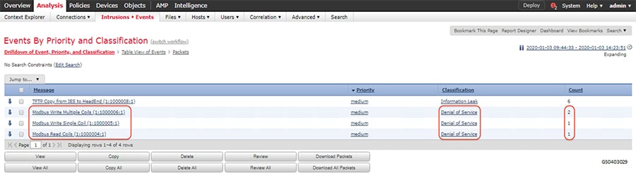
Deep Packet inspection of DNP3 using ISA3000
This scenario demonstrates how Cisco ISA3000 can be used to detect individual commands in a SCADA application. This functionality is extremely helpful in OT networks to provide visibility into the transactions that happen between endpoints and detect malicious behavior that may be result of a malware infection or an attack on Industrial Infrastructure. In particular, we will create IPS Rules on ISA3000 to detect individual DNP3 commands for READ, WRITE and UNSOLICITED operations and generate events for the same.
For details on the list of different OT protocols supported on ISA3000 refer to the following link.
https://www.cisco.com/c/en/us/products/collateral/security/industrial-security-appliance-3000/data-sheet-c78-735 839.pdf
Summary
Navigate to FMC > Policies > Access Control and click Intrusion as highlighted in the following figure.
Figure 122 Navigation to create new intrusion policy
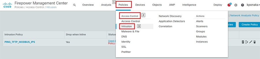
Click on Intrusion Rules as highlighted in the following figure.
Figure 123 Navigation to create new intrusion rule
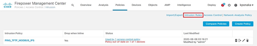
Click on Create Rule in the resulting page as highlighted in the following figure.
Figure 124 Create new intrusion rule
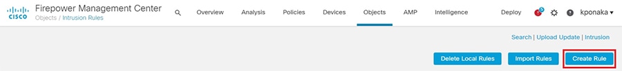
Fill in the details in the resulting page as highlighted in the following figure. As mentioned earlier, this scenario demonstrates DNP3 Protocol command detection. The figure shows a rule being created for DNP3 Read command and generate alerts for the same.
Figure 125 Defining intrusion rule properties
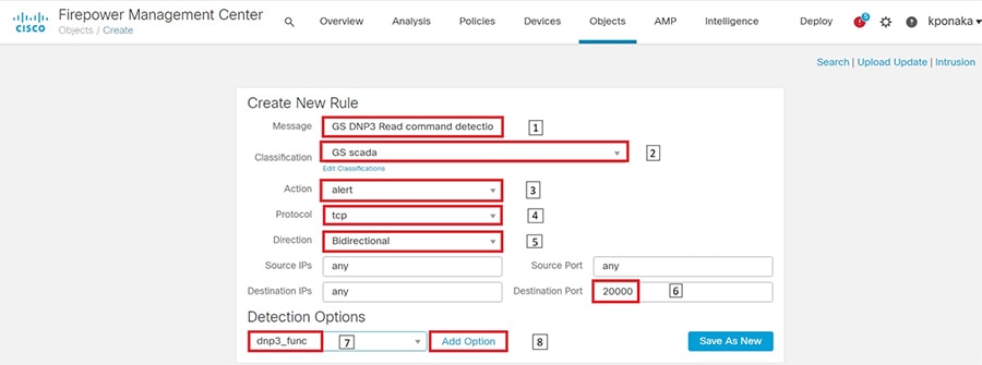
Identify the command to be inspected for as highlighted in the following figure. The figure shows the DNP3 Read command.
Figure 126 Define DNP3 function to be inspected
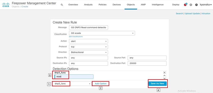
An IPS rule that can sort through all the traffic that gets sent across ISA3000 and find a DNP3 flow that issues a Read command has been created. This functionality opens up many possibilities for intrusion detection and enforcement. Once the rule is successfully added, we can add a few more rules by simply modifying the current rule and saving as new again. In our lab, we also created rules for Write and Unsolicited type DNP3 commands viz. write and enable_unsolicited.
Create a new Intrusion Policy with the newly created Intrusion rules as highlighted in the following figure.
Figure 127 Create new intrusion policy
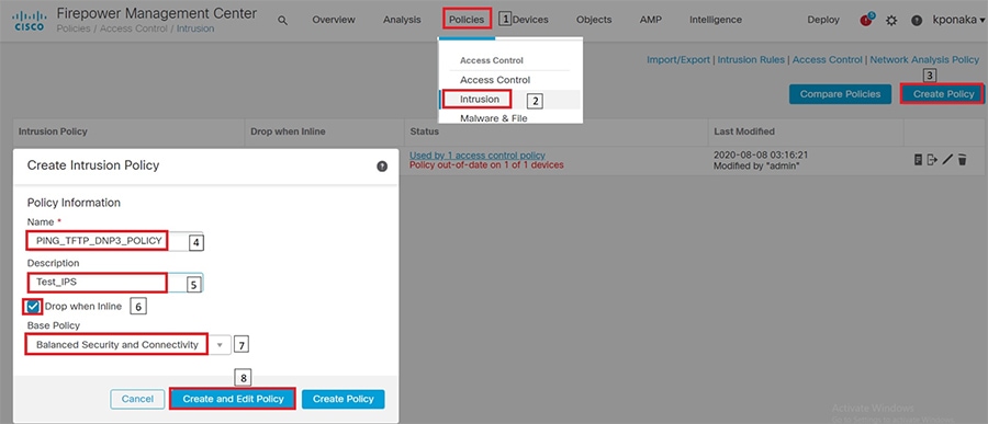
In the resulting edit policy window click rules and select the rules and corresponding actions for the rules as highlighted in the following figure.
It is recommended to not select Drop action especially in OT environments, where Availability has higher priority than Security. Giving visibility to the user in the form of events is important.
Figure 128 Add intrusion rules to intrusion policy
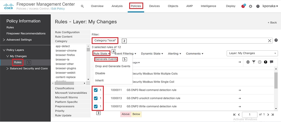
Click on the Back button at top right and then commit the changes in the resulting window as highlighted in the following figure.
Figure 129 Commit changes to intrusion policy
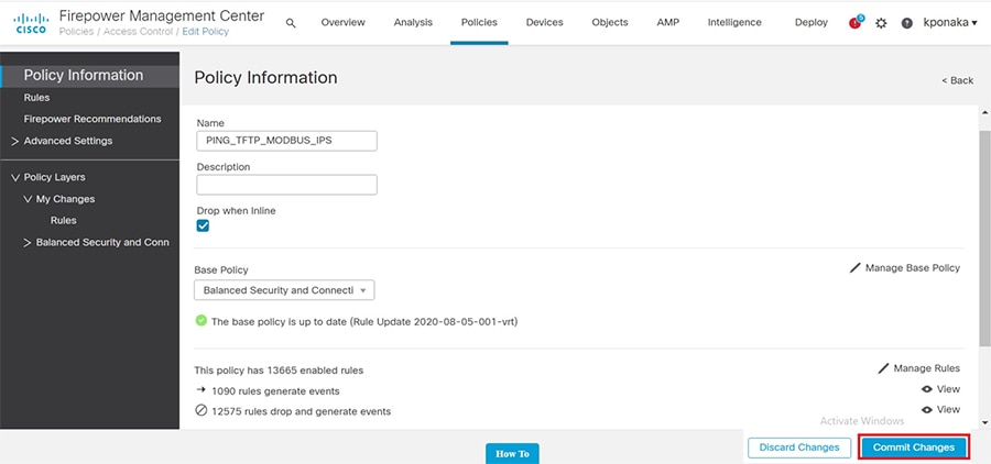
Create a new access control policy as highlighted in the following figure.
Figure 130 Create Access control policy for intrusion prevention
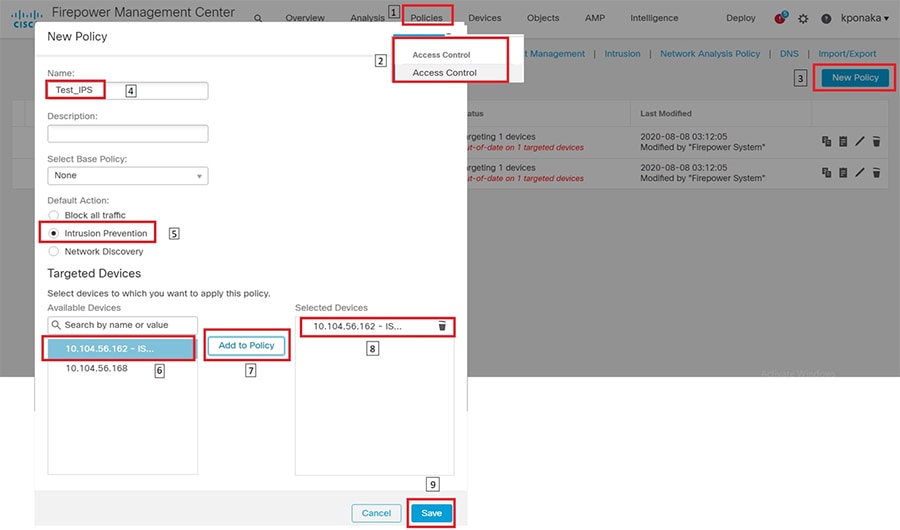
Add rule with the intended intrusion policy in the resulting window as highlighted in the following figure.
Figure 131 Attach intrusion policy to access control policy
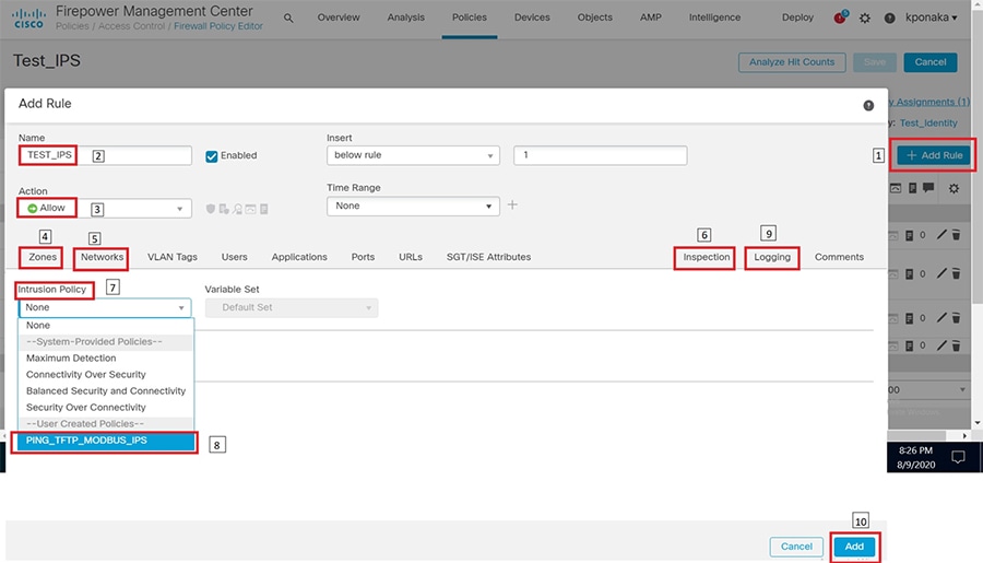
Save the newly added rule and deploy the policy onto Cisco ISA3000 as highlighted in the following figure.
Figure 132 Deploy newly created Access control policy for intrusion prevention
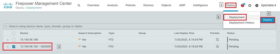
Verification
Initiate traffic and check if the applied policy classifies and identifies the type of application and the protocol it uses. This scenario was validated with DNP3 application and firewall policy applied on ISA3000 and ensuring that required events gets generated as highlighted in the following figure.
Figure 133 Verifying newly created Access control policy for intrusion prevention
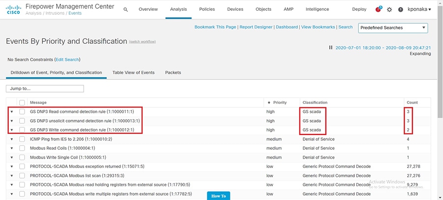
 Feedback