Cisco DNA Center for Industrial Automation Implementation Guide
Bias-Free Language
The documentation set for this product strives to use bias-free language. For the purposes of this documentation set, bias-free is defined as language that does not imply discrimination based on age, disability, gender, racial identity, ethnic identity, sexual orientation, socioeconomic status, and intersectionality. Exceptions may be present in the documentation due to language that is hardcoded in the user interfaces of the product software, language used based on RFP documentation, or language that is used by a referenced third-party product. Learn more about how Cisco is using Inclusive Language.
- Updated:
- January 18, 2022
Chapter: Cisco DNA Center for Industrial Automation Implementation Guide
Cisco DNA Center for Industrial Automation Implementation Guide
Overview
The following is a complementary guide to the Cisco DNA Center for Industrial Automation Design Guide ( https://www.cisco.com/c/en/us/td/docs/solutions/Verticals/Industrial_Automation/IA_Horizontal/IA_Networking/DNA_Center_IA/DNA_Center_IA.html), providing configuration details associated with the respective design recommendations.
Administration
Installation
For information on installing the Cisco DNA Center appliance, refer to:
https://www.cisco.com/c/en/us/support/cloud-systems-management/dna-center/products-installation-guides-list.html.
Licensing
For this implementation the Cisco Smart Software Manager On-Prem (Cisco SSM On-Prem) tool was used for Cisco DNA Center licensing. For Cisco SSM On-Prem installation, see:
https://www.cisco.com/web/software/286285517/152313/Smart_Software_Manager_On-Prem_8-202006_Installation_Guide.pdf.
To link SSM with Cisco DNA Center:
1.![]() From the Cisco SSM web interface, go to the API Tool Kit menu.
From the Cisco SSM web interface, go to the API Tool Kit menu.
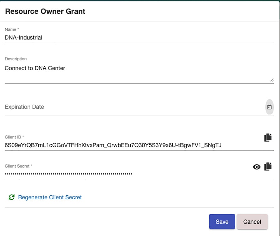
2.![]() Under the API Console tab, click Create and choose Resource Owner Grant from the drop-down list.
Under the API Console tab, click Create and choose Resource Owner Grant from the drop-down list.
Figure 1 Cisco SSM API Tool Kit
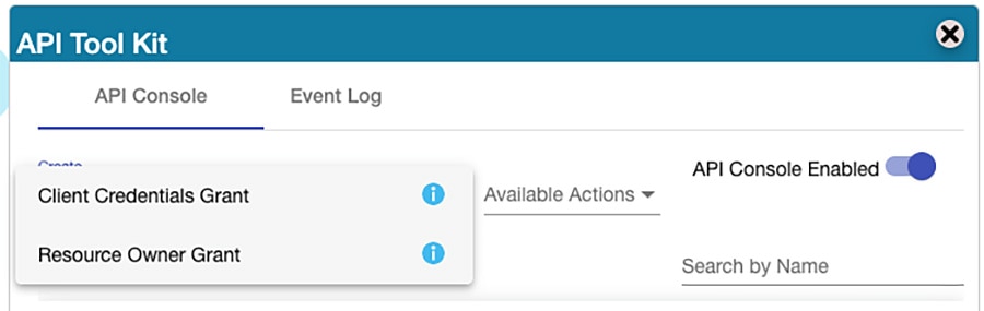
Figure 2 Cisco SSM Resource Owner Grant
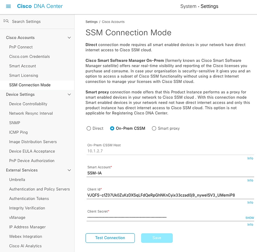
1.![]() Navigate to System > Settings and under Cisco Accounts choose SSM Connection Mode.
Navigate to System > Settings and under Cisco Accounts choose SSM Connection Mode.
2.![]() Click the On-Prem CSSM radio button and enter the information from the SSM Resource Owner Grant.
Click the On-Prem CSSM radio button and enter the information from the SSM Resource Owner Grant.
Figure 3 Cisco DNA Center SSM Configuration
Proxy
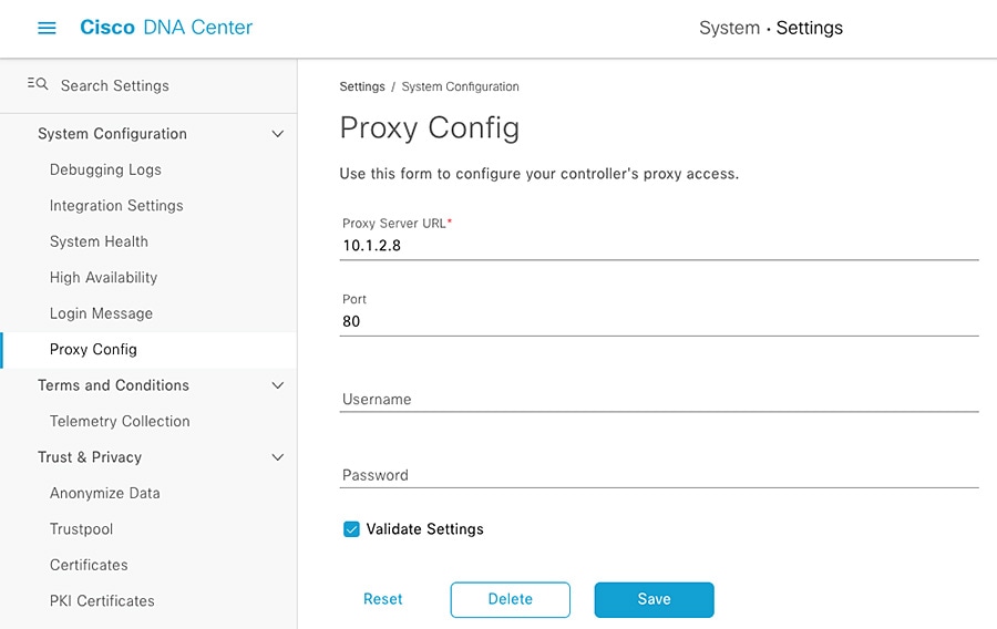
In addition to using SSM for licensing, in this implementation we configured Cisco DNA Center to use a proxy for external web communication for tasks such as software image downloads. Proxy communication can be configured during Cisco DNA Center cluster installation or added later in System > Settings > System Configuration >Proxy Config.
Figure 4 Cisco DNA Center Proxy Configuration
Configuration
Users and Roles
For this implementation, the default Cisco DNA Center users and roles were used:
■![]() SUPER-ADMIN-ROLE—This role has full access within Cisco DNA Center to manage any devices, integrations, and Cisco DNA Center configuration.
SUPER-ADMIN-ROLE—This role has full access within Cisco DNA Center to manage any devices, integrations, and Cisco DNA Center configuration.
■![]() NETWORK-ADMIN-ROLE—This role can view and modify devices and configurations, but does not have privileges to make any changes to Cisco DNA Center itself.
NETWORK-ADMIN-ROLE—This role can view and modify devices and configurations, but does not have privileges to make any changes to Cisco DNA Center itself.
■![]() OBSERVER-ROLE—This role has read-only access to view non-sensitive information.
OBSERVER-ROLE—This role has read-only access to view non-sensitive information.
Navigate to System > Users & Roles to view or modify users and roles.
Integrations
Cisco DNA Center integrates with Cisco ISE to establish unified environment tracking and control. To establish the communication between Cisco DNA Center and ISE, do the following:
1.![]() From the Cisco DNA Center web interface, navigate to System > Settings.
From the Cisco DNA Center web interface, navigate to System > Settings.
2.![]() From the Settings menu, choose External Services > Authentication and Policy Servers.
From the Settings menu, choose External Services > Authentication and Policy Servers.
3.![]() From the Add drop-down list, choose ISE.
From the Add drop-down list, choose ISE.
a.![]() On the Add ISE server slide-in pane, in the Server IP Address field, enter the IP address of the ISE Primary Admin Node (PAN).
On the Add ISE server slide-in pane, in the Server IP Address field, enter the IP address of the ISE Primary Admin Node (PAN).
b.![]() In the Shared Secret field, enter the secret for network access devices.
In the Shared Secret field, enter the secret for network access devices.
c.![]() In the Username field, enter the ISE PAN administrator username.
In the Username field, enter the ISE PAN administrator username.
d.![]() In the Password field, enter the ISE PAN administrator password.
In the Password field, enter the ISE PAN administrator password.
e.![]() In the FQDN field, enter the fully-qualified domain name of the ISE PAN.
In the FQDN field, enter the fully-qualified domain name of the ISE PAN.
Upgrade
Information for upgrading Cisco DNA Center can be found at:
https://www.cisco.com/c/en/us/td/docs/cloud-systems-management/network-automation-and-management/dna-center/upgrade/b_cisco_dna_center_upgrade_guide.html.
Note: Cisco DNA Center availability is impacted while it is upgrading, however network devices and clients can continue to communicate normally with services such as ISE, DNS, and so on.
Design
The Design feature set in Cisco DNA Center allows users to prepare the system to manage the intended infrastructure with the correct configurations and services. The process is as follows:
Sites
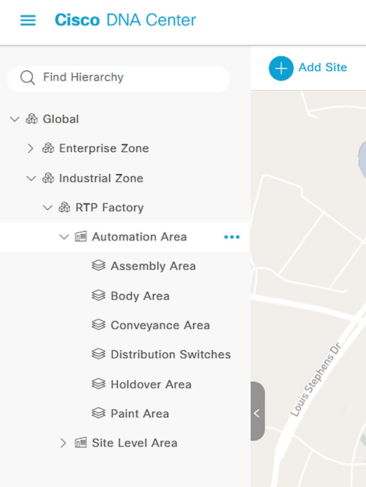
Cisco DNA Center allows users to logically organize managed systems into hierarchical Sites, which can be geographical or logical groups for ease of management and configuration consolidation. To create Sites, do the following:
1.![]() From the Cisco DNA Center web interface, navigate to Design > Network Hierarchy.
From the Cisco DNA Center web interface, navigate to Design > Network Hierarchy.
2.![]() Click the Add Site button and select the appropriate option (for example, choose Add Area for a logical zone in the network).
Click the Add Site button and select the appropriate option (for example, choose Add Area for a logical zone in the network).
a.![]() Enter the name and choose the immediate parent floor, building, or area.
Enter the name and choose the immediate parent floor, building, or area.
3.![]() Repeat as needed to build the geographical or logical hierarchy suited to your environment.
Repeat as needed to build the geographical or logical hierarchy suited to your environment.
Figure 5 Cisco DNA Center Network Hierarchy
Note: Moving devices between Sites will potentially initiate configuration changes; with Device Controllability enabled and Telemetry settings defined for each Site, moving a device to a new Site will trigger Cisco DNA Center to push configuration changes to align with the new Site settings. In addition, a Site cannot be deleted while it has devices assigned to it.
Network Settings
Network Settings allow the user to tailor what Cisco DNA Center will configure by default on a per-Site basis, which helps simplify and streamline configuration. This guide will focus on Network and Telemetry settings as applicable to Industrial Automation switching. Network settings include services such as DHCP, DNS, NTP, AAA, and so on that the managed host will use for the respective network communications. Telemetry settings consist of SNMP Traps, Syslog, and NetFlow, which Cisco DNA center will use for monitoring device health and communication. To define Network Settings, do the following:
1.![]() From the Cisco DNA Center web interface, navigate to Design > Network Settings.
From the Cisco DNA Center web interface, navigate to Design > Network Settings.
2.![]() On the Network tab, navigate to the desired Site from the left hierarchy.
On the Network tab, navigate to the desired Site from the left hierarchy.
a.![]() Click the Add Servers button.
Click the Add Servers button.
b.![]() Check the checkbox next to each desired service. Click the OK button.
Check the checkbox next to each desired service. Click the OK button.
c.![]() For each Server chosen, enter the required information:
For each Server chosen, enter the required information:
–![]() For AAA Server, check the Network and Client/Endpoint checkboxes to define the AAA server IP address and protocol to be used by the network device and any connected endpoints. In this implementation, the ISE PAN and RADIUS are used for both Network and Client/Endpoint. See note at the bottom of this section regarding AAA and RADIUS configuration.
For AAA Server, check the Network and Client/Endpoint checkboxes to define the AAA server IP address and protocol to be used by the network device and any connected endpoints. In this implementation, the ISE PAN and RADIUS are used for both Network and Client/Endpoint. See note at the bottom of this section regarding AAA and RADIUS configuration.
–![]() For DHCP Server, enter the IP address of the DHCP server.
For DHCP Server, enter the IP address of the DHCP server.
–![]() For DNS Server, enter the fully-qualified domain name in the Domain Name field and the DNS IP address in the Primary field.
For DNS Server, enter the fully-qualified domain name in the Domain Name field and the DNS IP address in the Primary field.
–![]() For NTP Server, enter the NTP server IP address in the NTP field.
For NTP Server, enter the NTP server IP address in the NTP field.
–![]() For Time Zone, choose the appropriate option from the Time Zone drop-down list.
For Time Zone, choose the appropriate option from the Time Zone drop-down list.
–![]() For Message of the Day, check the Do not override the existing MOTD banner on the device checkbox.
For Message of the Day, check the Do not override the existing MOTD banner on the device checkbox.
d.![]() Repeat for each Site accordingly.
Repeat for each Site accordingly.
3.![]() On the Telemetry tab, navigate to the desired Site from the left hierarchy.
On the Telemetry tab, navigate to the desired Site from the left hierarchy.
a.![]() For SNMP Traps, check the Use Cisco DNA Center as the SNMP trap server checkbox.
For SNMP Traps, check the Use Cisco DNA Center as the SNMP trap server checkbox.
b.![]() For Syslogs, check the Use Cisco DNA Center as syslog server checkbox.
For Syslogs, check the Use Cisco DNA Center as syslog server checkbox.
c.![]() For NetFlow, you can check the Use Cisco DNA Center as NetFlow collector server or Add an external NetFlow collector server checkbox. We recommend to leave these unchecked and configure NetFlow using templates for the industrial network containing a majority of industrial switches.
For NetFlow, you can check the Use Cisco DNA Center as NetFlow collector server or Add an external NetFlow collector server checkbox. We recommend to leave these unchecked and configure NetFlow using templates for the industrial network containing a majority of industrial switches.
d.![]() For Wired Client Data Collection, check the Monitor wired clients checkbox. This feature enables IP Device Tracking (IPDT) on the device which tracks IP address to SGT bindings for endpoints to be used in TrustSec policy. See note at the bottom of this section regarding IPDT.
For Wired Client Data Collection, check the Monitor wired clients checkbox. This feature enables IP Device Tracking (IPDT) on the device which tracks IP address to SGT bindings for endpoints to be used in TrustSec policy. See note at the bottom of this section regarding IPDT.
f.![]() Repeat for each Site accordingly.
Repeat for each Site accordingly.
Note: Regarding AAA and RADIUS—As of release 2.2.3.3, Cisco DNA Center will apply all necessary configuration for AAA and RADIUS communication, however the following commands need to be added through a template for the IE3400 switch to have successful communication with ISE:
Note: Regarding IPDT—For classic Cisco IOS platforms, the recommended option is to modify the standard IP address used with the IPDT feature prior to the implementation of IPDT. Using the default can cause the keepalive messages to be populated with duplicate IP addresses for the source and destination, potentially causing a communication issue for the connected end devices.
The following command can be added through a template:
For more details see:
https://www.cisco.com/c/en/us/support/docs/ip/address-resolution-protocol-arp/118630-technote-ipdt-00.html.
Note: Not all Network Settings are applied simultaneously. Given that Device Controllability is enabled, Telemetry settings are applied when a device is assigned to a Site and the Network specific settings (AAA, DHCP, and so on) are applied when a device is provisioned.
Image Repository
Cisco DNA Center communicates with Cisco.com to retrieve available software images for the suite of supported devices, whether directly or through a proxy. Similar to Network Settings, software versions can be specified on a per-Site basis to ensure consistent operation across devices. After devices have been discovered and added to Sites, you can change the Golden Image in Image Repository for each device type by doing the following:
1.![]() From the Cisco DNA Center web interface, navigate to Design > Image Repository.
From the Cisco DNA Center web interface, navigate to Design > Image Repository.
2.![]() Choose the desired Site from the left hierarchy.
Choose the desired Site from the left hierarchy.
3.![]() From the Devices list, expand each device to see all available software images. Click the arrow button in the Golden Image column to download the relevant image, and in the subsequent Download Image dialogue box, check the Mark the image as golden after download checkbox to set that image as the Golden Image for that specific device type.
From the Devices list, expand each device to see all available software images. Click the arrow button in the Golden Image column to download the relevant image, and in the subsequent Download Image dialogue box, check the Mark the image as golden after download checkbox to set that image as the Golden Image for that specific device type.
Templates
Cisco DNA Center Templates can be used to automate any configuration on discovered or managed devices, whether they are new or have existing configurations. See the Appendix for examples and tips on using templates. To create a template, do the following:
1.![]() From the Cisco DNA Center web interface, navigate to Tools > Template Editor.
From the Cisco DNA Center web interface, navigate to Tools > Template Editor.
2.![]() Click the Plus button and choose Create Template.
Click the Plus button and choose Create Template.
a.![]() Under Template Type, click the Regular Template radio button.
Under Template Type, click the Regular Template radio button.
b.![]() Under Template Language, click the Velocity radio button. The Jinja option can be used as well; for more details refer to Cisco DNA Center Documentation:
Under Template Language, click the Velocity radio button. The Jinja option can be used as well; for more details refer to Cisco DNA Center Documentation:
https://www.cisco.com/c/en/us/td/docs/cloud-systems-management/network-automation-and-management/dna-center/2-2-3/user_guide/b_cisco_dna_center_ug_2_2_3.html.
c.![]() Under Name, enter a name for the template.
Under Name, enter a name for the template.
d.![]() From the Project Name drop-down list, choose the relevant project. For example, choose Onboarding Configuration to create a template to be used for initial configuration of a new device during Plug and Play.
From the Project Name drop-down list, choose the relevant project. For example, choose Onboarding Configuration to create a template to be used for initial configuration of a new device during Plug and Play.
–![]() Click the Edit link under Device Type(s).
Click the Edit link under Device Type(s).
–![]() Navigate through the expandable lists to check the boxes for all relevant devices.
Navigate through the expandable lists to check the boxes for all relevant devices.
e.![]() At the top, click the Back to Add New Template link.
At the top, click the Back to Add New Template link.
f.![]() From the Software Type drop-down list, choose the appropriate Cisco software type.
From the Software Type drop-down list, choose the appropriate Cisco software type.
h.![]() The Template Editor pane will display, allowing you to enter CLI commands for configuration. Note that variables may be used by denoting a dollar sign with the argument; for example:
The Template Editor pane will display, allowing you to enter CLI commands for configuration. Note that variables may be used by denoting a dollar sign with the argument; for example:
i.![]() After adding all desired configuration, from the Actions drop-down list choose Save and then choose Commit.
After adding all desired configuration, from the Actions drop-down list choose Save and then choose Commit.
Note: Any changes to existing templates do not trigger a configuration change on associated devices until they are provisioned again.
Network Profiles
Cisco DNA Center Network Profiles allow you to attach templates to Sites so that when a device is added to the Site, Cisco DNA Center will automatically apply the configuration specified in the template. To create a Network Profile, do the following:
1.![]() From the Cisco DNA Center web interface, navigate to Design > Network Profiles.
From the Cisco DNA Center web interface, navigate to Design > Network Profiles.
2.![]() From the Add Profile drop-down list, choose the appropriate device type.
From the Add Profile drop-down list, choose the appropriate device type.
a.![]() For the Profile Name field, enter a name.
For the Profile Name field, enter a name.
b.![]() Choose the OnBoarding Template(s) tab to attach any templates to be used during Plug and Play for unconfigured devices or the Day-N Template(s) tab to attach any templates for additional configuration to be pushed during provisioning.
Choose the OnBoarding Template(s) tab to attach any templates to be used during Plug and Play for unconfigured devices or the Day-N Template(s) tab to attach any templates for additional configuration to be pushed during provisioning.
c.![]() Click the Add Template button.
Click the Add Template button.
–![]() On the Add Template slide-in pane, choose the relevant template from the Templates list.
On the Add Template slide-in pane, choose the relevant template from the Templates list.
Note: Adding a template to a Network Profile will not trigger a configuration change on applicable existing devices until they are provisioned again.
Automation
The automation features in Cisco DNA Center provide a powerful toolset for monitoring and managing your infrastructure. This helps with maintaining inventory, ensuring consistent configuration, and driving compliance. The process is as follows:
1.![]() Manage devices with Discovery or Plug and Play
Manage devices with Discovery or Plug and Play
2.![]() Monitor with Topology and Inventory
Monitor with Topology and Inventory
3.![]() Maintain devices SWIM and RMA workflows
Maintain devices SWIM and RMA workflows
There are three main workflows in Industrial Automation networks for adding devices to Cisco DNA Center—Discovery, Plug and Play, and Offline provisioning. In the following sections we give details about the Discovery and Plug and Play methods and discuss some of the variety of Inventory features that can used to manage these devices.
Note: For Offline provisioning we use Cisco DNA Center Discovery; the device is configured manually via CLI or other management tools and is then discovered by Cisco DNA Center when network connectivity is established. See the Appendix for further details.
Discovery
Cisco DNA Center can discover network devices and add them to the managed inventory, which can help administrators maintain and monitor the environment from a central viewpoint. The Device Controllability feature can be added to the discovery process to prepare devices for management through Cisco DNA Center when subsequent provisioning configuration or inventory changes are made. To discover devices, do the following:
1.![]() From the Cisco DNA Center web interface, navigate to Tools > Discovery.
From the Cisco DNA Center web interface, navigate to Tools > Discovery.
2.![]() Click the Add Discovery button.
Click the Add Discovery button.
a.![]() Note at the bottom if Device Controllability is enabled (it is enabled by default). If enabled, Cisco DNA Center will configure SNMP or NETCONF credentials on the device during Discovery (it will not overwrite existing SNMP or NETCONF configuration). We recommend using Device Controllability to make use of the Cisco DNA Center monitoring capabilities.
Note at the bottom if Device Controllability is enabled (it is enabled by default). If enabled, Cisco DNA Center will configure SNMP or NETCONF credentials on the device during Discovery (it will not overwrite existing SNMP or NETCONF configuration). We recommend using Device Controllability to make use of the Cisco DNA Center monitoring capabilities.
Note: Currently Cisco IE switches can be discovered via NETCONF however there are no additional capabilities from it in the current release. If you do not want any configuration changes made to the device(s), click the Disable link.
b.![]() In the Discovery Name field, enter a name for the relevant device(s) being discovered.
In the Discovery Name field, enter a name for the relevant device(s) being discovered.
c.![]() Under IP Address/Range, choose the appropriate Discovery Type :
Under IP Address/Range, choose the appropriate Discovery Type :
–![]() For CDP, enter the IP Address of a device to be discovered. You can change the CDP Level to something other than the default to detect more or fewer neighboring devices to the original device.
For CDP, enter the IP Address of a device to be discovered. You can change the CDP Level to something other than the default to detect more or fewer neighboring devices to the original device.
–![]() For IP Address/Range, in the From field enter the lowest IP address to be scanned. In the To field, enter the highest IP address to be scanned. If only one device is being discovered, enter the same IP address in both fields. The IP address method is recommended for discovering devices.
For IP Address/Range, in the From field enter the lowest IP address to be scanned. In the To field, enter the highest IP address to be scanned. If only one device is being discovered, enter the same IP address in both fields. The IP address method is recommended for discovering devices.
–![]() For LLDP, enter the IP Address of a device to be discovered. You can change the LLDP Level to something other than the default to detect more or fewer neighboring devices to the original device.
For LLDP, enter the IP Address of a device to be discovered. You can change the LLDP Level to something other than the default to detect more or fewer neighboring devices to the original device.
d.![]() Under Credentials, click the toggle buttons of the necessary entities under CLI, SNMPv2c Read, SNMPv2c Write, and so on. The device being discovered must accept at least one form of these credentials for discovery to be successful and CLI credentials are mandatory.
Under Credentials, click the toggle buttons of the necessary entities under CLI, SNMPv2c Read, SNMPv2c Write, and so on. The device being discovered must accept at least one form of these credentials for discovery to be successful and CLI credentials are mandatory.
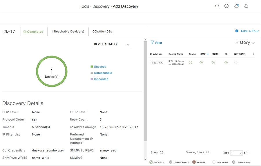
e.![]() Click the Discover button. The Discovery process will begin and show progress on the Discovery page with automatic refreshing to display the current status. When the process is finished, it will display success or failure results and add the discovered device to Inventory.
Click the Discover button. The Discovery process will begin and show progress on the Discovery page with automatic refreshing to display the current status. When the process is finished, it will display success or failure results and add the discovered device to Inventory.
Figure 6 Cisco DNA Center Discovery
After discovery, you can assign the device to a Site and Provision, which can be done individually or in the same step.
1.![]() Navigate to Provision > Network Devices > Inventory.
Navigate to Provision > Network Devices > Inventory.
2.![]() From the left Hierarchy, choose Global > Unassigned Devices.
From the left Hierarchy, choose Global > Unassigned Devices.
3.![]() Locate the newly discovered device in the list and check the checkbox. From the Actions drop-down list, choose Provision > Assign Device to Site.
Locate the newly discovered device in the list and check the checkbox. From the Actions drop-down list, choose Provision > Assign Device to Site.
a.![]() On the Assign Device to Site slide-in pane, click the Choose a Site link. Click the desired site from the hierarchy then click the Save button. Click the Next button.
On the Assign Device to Site slide-in pane, click the Choose a Site link. Click the desired site from the hierarchy then click the Save button. Click the Next button.
b.![]() Review the settings that will be deployed, then click the Next button.
Review the settings that will be deployed, then click the Next button.
c.![]() Click the Now radio button to make the change immediately (if scheduling the assignment for a future date and time, click the Later radio button and specify the date and time).
Click the Now radio button to make the change immediately (if scheduling the assignment for a future date and time, click the Later radio button and specify the date and time).
After the device has been assigned, it will be in the device list of the specified Site. Note that when Device Controllability is enabled, assigning the device to a Site will trigger the following configurations (where applicable):
1.![]() Navigate to Provision > Network Devices > Inventory.
Navigate to Provision > Network Devices > Inventory.
2.![]() From the left Hierarchy, choose Global > Unassigned Devices.
From the left Hierarchy, choose Global > Unassigned Devices.
3.![]() Locate the newly discovered device in the list and check the checkbox. From the Actions drop-down list, choose Provision > Provision device.
Locate the newly discovered device in the list and check the checkbox. From the Actions drop-down list, choose Provision > Provision device.
a.![]() On the Assign Site step, click the Choose a site link and choose the desired Site. Click the Save button, then click the Next button. (Note that if Site assignment was done previously no action is needed here).
On the Assign Site step, click the Choose a site link and choose the desired Site. Click the Save button, then click the Next button. (Note that if Site assignment was done previously no action is needed here).
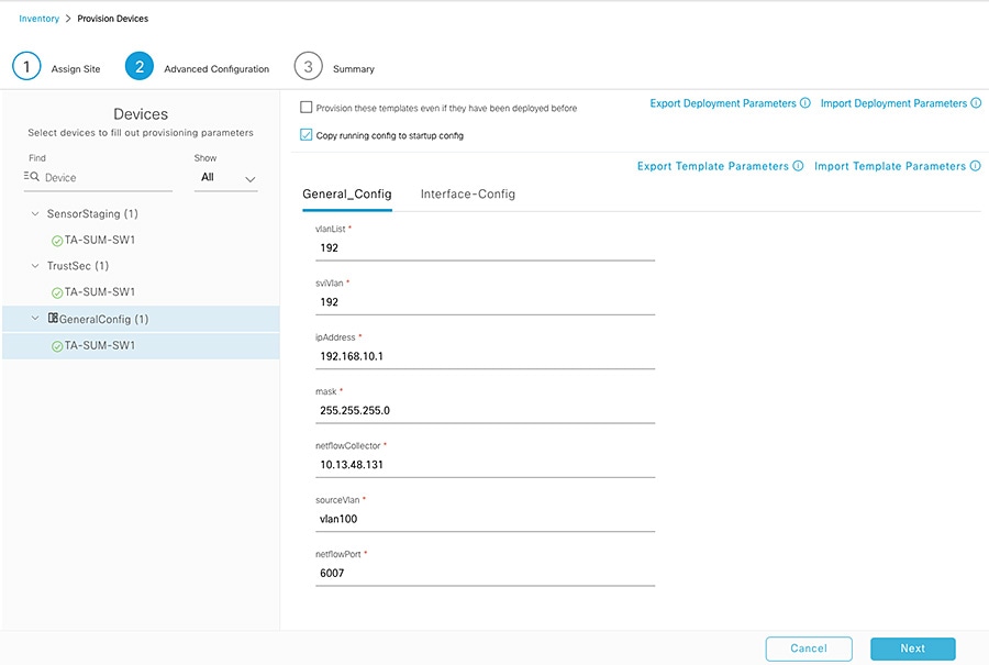
b.![]() On the Advanced Configuration step, choose the device from the Devices list if there are any template settings to be configured. When finished, or if no template is applied, click the Next button.
On the Advanced Configuration step, choose the device from the Devices list if there are any template settings to be configured. When finished, or if no template is applied, click the Next button.
c.![]() On the Summary step, review the configuration to be added to the device. Click the Deploy button.
On the Summary step, review the configuration to be added to the device. Click the Deploy button.
After the device has been provisioned, it will be in the device list of the specified Site.
Note: For Cisco DNA Center release 2.2.3.3:
■![]() Provisioning a device that has been already been configured with AAA before being discovered will fail. Remove any AAA configuration before pushing AAA using Cisco DNA Center.
Provisioning a device that has been already been configured with AAA before being discovered will fail. Remove any AAA configuration before pushing AAA using Cisco DNA Center.
■![]() There is a known defect in which AAA provisioning fails for the Cisco IE 2000 switch and subsequent provisioning tasks are aborted.
There is a known defect in which AAA provisioning fails for the Cisco IE 2000 switch and subsequent provisioning tasks are aborted.
Plug and Play
One of the most powerful tools of Cisco DNA Center is Plug and Play (PnP). You can prepare for new, unconfigured devices in advance or detect them on the network in real time, and Cisco DNA Center can claim and configure these devices without user interaction on the device itself. The process is as follows:
1.![]() Connect the new device to the network. See the Appendix for notes on PnP network preparation.
Connect the new device to the network. See the Appendix for notes on PnP network preparation.
2.![]() From the Cisco DNA Center web interface, navigate to Provision > Network Devices > Plug and Play.
From the Cisco DNA Center web interface, navigate to Provision > Network Devices > Plug and Play.
3.![]() The Plug and Play page will show any currently Unclaimed devices. These can be claimed and added to Inventory. For preparing for future devices to be claimed, skip to Step 5.
The Plug and Play page will show any currently Unclaimed devices. These can be claimed and added to Inventory. For preparing for future devices to be claimed, skip to Step 5.
4.![]() Check the checkbox for all devices being claimed and from the Actions drop-down list choose Claim.
Check the checkbox for all devices being claimed and from the Actions drop-down list choose Claim.
a.![]() On the Assign Site step, under the Site column, click the Assign link. Choose the appropriate Site and click the Assign button. Repeat for any other devices or check the Apply Site to All checkbox to configure them all for the same Site. Click the Next button.
On the Assign Site step, under the Site column, click the Assign link. Choose the appropriate Site and click the Assign button. Repeat for any other devices or check the Apply Site to All checkbox to configure them all for the same Site. Click the Next button.
b.![]() On the Assign Configuration step, a software image and template can be chosen to apply to the device when it is claimed. The template is automatically chosen based on the Onboarding templates for the given device type at the given Site. Click the software image or template link to show the Configuration slide-in pane, where the image can be changed or removed (if no software image change is desired). Note that if the image is being changed, the device will reload during the PnP process. The template can also be changed or removed. When the desired image and template are selected (or removed), click the Save button. Then click the Next button.
On the Assign Configuration step, a software image and template can be chosen to apply to the device when it is claimed. The template is automatically chosen based on the Onboarding templates for the given device type at the given Site. Click the software image or template link to show the Configuration slide-in pane, where the image can be changed or removed (if no software image change is desired). Note that if the image is being changed, the device will reload during the PnP process. The template can also be changed or removed. When the desired image and template are selected (or removed), click the Save button. Then click the Next button.
c.![]() On the Provision Templates step, choose the device from the Devices list and enter any required information as specified in the template (the values for each template variable). Repeat for all devices. Click the Next button.
On the Provision Templates step, choose the device from the Devices list and enter any required information as specified in the template (the values for each template variable). Repeat for all devices. Click the Next button.
d.![]() On the Summary step, review the configuration and details. Click the Claim button to begin the claiming process, which will make configuration changes on the device and add it to Inventory.
On the Summary step, review the configuration and details. Click the Claim button to begin the claiming process, which will make configuration changes on the device and add it to Inventory.
5.![]() To prepare Cisco DNA Center to claim devices not yet connected to the network in advance, from the Plug and Play page click the Add Devices button.
To prepare Cisco DNA Center to claim devices not yet connected to the network in advance, from the Plug and Play page click the Add Devices button.
6.![]() On the Add Devices slide-in pane, choose the appropriate method:
On the Add Devices slide-in pane, choose the appropriate method:
–![]() Single Device —Enter the Serial Number, Product ID, and optional Device Name. Click the Add Device button (you will claim it manually as previously discussed once it is detected by Cisco DNA Center) or the Add+Claim button (the claim is configured now).
Single Device —Enter the Serial Number, Product ID, and optional Device Name. Click the Add Device button (you will claim it manually as previously discussed once it is detected by Cisco DNA Center) or the Add+Claim button (the claim is configured now).
–![]() Bulk Devices —Click the Download File Template button to download a.CSV file template, which instructs on how to specify multiple devices at once. Upload the file and click the Import Devices button.
Bulk Devices —Click the Download File Template button to download a.CSV file template, which instructs on how to specify multiple devices at once. Upload the file and click the Import Devices button.
–![]() Smart Account Devices —For further details see the Cisco DNA Center User Guide:
Smart Account Devices —For further details see the Cisco DNA Center User Guide:
https://www.cisco.com/c/en/us/td/docs/cloud-systems-management/network-automation-and-management/dna-center/2-2-3/user_guide/b_cisco_dna_center_ug_2_2_3/b_cisco_dna_center_ug_2_2_3_chapter_01101.html#id_89077.
After the devices have been claimed, they can be provisioned by following Steps 3-5 in the Discovery section.
Topology
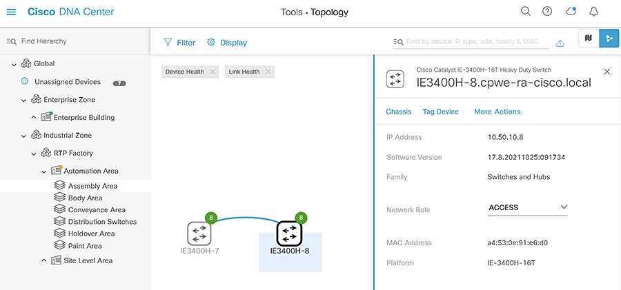
The Topology view in Cisco DNA Center is a useful tool for visualizing the network because it shows devices and their connections as well as device and link details, giving administrators a better understanding of the network and its health. To view the Topology, do the following:
1.![]() From the Cisco DNA Center web interface, navigate to Tools > Topology.
From the Cisco DNA Center web interface, navigate to Tools > Topology.
2.![]() From the left Hierarchy, choose a Site to view the respective devices and links.
From the left Hierarchy, choose a Site to view the respective devices and links.
From the Topology view you can:
■![]() Hover over a link to view the speed or click on a link to view the connection details.
Hover over a link to view the speed or click on a link to view the connection details.
■![]() Hover over a device to view the device type and network details or click on the device to view additional details and navigate to other Cisco DNA Center menus for the given device.
Hover over a device to view the device type and network details or click on the device to view additional details and navigate to other Cisco DNA Center menus for the given device.
■![]() Filter what is shown based on specific network criteria. Click the Filter button at the top and choose VRF, VLAN, Routing, or Tagging. This will narrow the scope of what is displayed to only devices and connections that meet the specified network criteria.
Filter what is shown based on specific network criteria. Click the Filter button at the top and choose VRF, VLAN, Routing, or Tagging. This will narrow the scope of what is displayed to only devices and connections that meet the specified network criteria.
Figure 7 Cisco DNA Center Topology
Inventory
Cisco DNA Center Inventory has a wide variety of capabilities to manage devices. Once a device has been discovered or added to inventory through PnP, it can be provisioned, which adds the specified Network Settings to devices. In addition, after devices are fully managed, Inventory can provide compliance and software verification, as well as options to change device settings or initiate device replacement. The following section details some of the monitoring and management capabilities in Inventory.
Software Image Management
Devices can be upgraded automatically through Cisco DNA Center, which downloads the image from Cisco.com, pushes the image to the device, and performs the upgrade. In addition, you have the option of uploading a desired image to Cisco DNA Center and upgrades can be scheduled in advance. After ensuring the image is set as Golden (see the Image Repository section), update a device’s software image by doing the following:
1.![]() From the Cisco DNA Center web interface, navigate to Provision > Network Devices > Inventory.
From the Cisco DNA Center web interface, navigate to Provision > Network Devices > Inventory.
2.![]() From the left Hierarchy, choose the Site with the device to be upgraded.
From the left Hierarchy, choose the Site with the device to be upgraded.
3.![]() Check the checkbox next to the device to be upgraded and from the Actions drop-down list choose Software Image > Update Image.
Check the checkbox next to the device to be upgraded and from the Actions drop-down list choose Software Image > Update Image.
4.![]() From the Image Upgrade slide-in pane, check the checkbox of the device to be upgraded and click the Next button.
From the Image Upgrade slide-in pane, check the checkbox of the device to be upgraded and click the Next button.
5.![]() Under Software Distribution, click the Now radio button (if scheduling an upgrade for a future date and time, click the Later radio button and specify the date and time). Click the Next button.
Under Software Distribution, click the Now radio button (if scheduling an upgrade for a future date and time, click the Later radio button and specify the date and time). Click the Next button.
6.![]() Under Software Activation, check the Initiate Image Activation after Image Distribution is finished checkbox. If you just want to push the image to the device and not launch the upgrade, leave the box unchecked and either specify the start date and time or click the Skip Activation link at the bottom. You also have the option of checking the Initiate Flash Cleanup after Activation checkbox, which will automatically remove unused software image files from the device after the upgrade. Click the Next button.
Under Software Activation, check the Initiate Image Activation after Image Distribution is finished checkbox. If you just want to push the image to the device and not launch the upgrade, leave the box unchecked and either specify the start date and time or click the Skip Activation link at the bottom. You also have the option of checking the Initiate Flash Cleanup after Activation checkbox, which will automatically remove unused software image files from the device after the upgrade. Click the Next button.
7.![]() On the Summary step, review the upgrade details and then click the Submit button.
On the Summary step, review the upgrade details and then click the Submit button.
Notes on software image management:
■![]() Cisco DNA Center will give priority to installing and running the image on sdflash if it is present. If the software is running in Install mode from flash with sdflash present, the upgrade will fail.
Cisco DNA Center will give priority to installing and running the image on sdflash if it is present. If the software is running in Install mode from flash with sdflash present, the upgrade will fail.
■![]() If the image is running on sdflash and it is formatted as vfat the upgrade will be successful. If it is formatted in ext4 only (for Cisco Cyber Vision) the upgrade will fail. See IOS XE Devices with Cisco Cyber Vision for details on partitioning sdflash, which allows the software image and iox applications to run concurrently from sdflash.
If the image is running on sdflash and it is formatted as vfat the upgrade will be successful. If it is formatted in ext4 only (for Cisco Cyber Vision) the upgrade will fail. See IOS XE Devices with Cisco Cyber Vision for details on partitioning sdflash, which allows the software image and iox applications to run concurrently from sdflash.
■![]() The update process will trigger a reload on the device which will impact network connectivity for the device and any connected endpoints.
The update process will trigger a reload on the device which will impact network connectivity for the device and any connected endpoints.
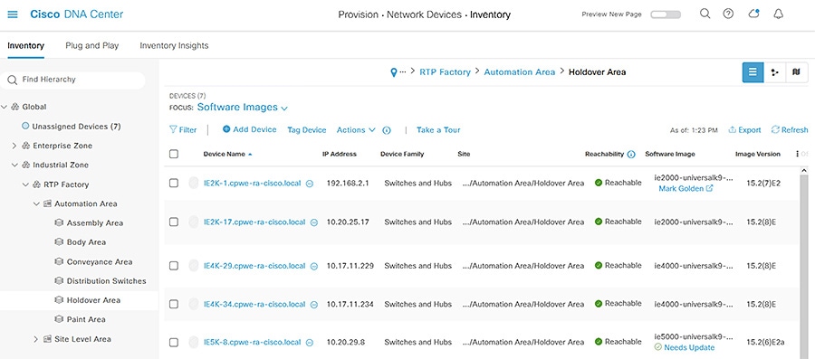
On the Inventory page, you can review the status of the update by choosing Software Image > Image Update Status from the Actions drop-down list. In addition, from Inventory you can review which devices are not running the specified Golden Image with the Compliance status column or choosing Software Images from the Focus drop-down list.
Figure 8 Cisco DNA Center Inventory
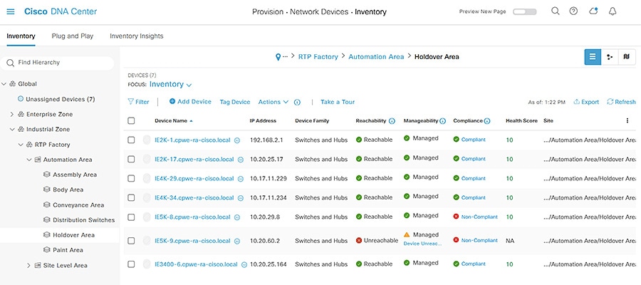
Figure 9 Cisco DNA Center Inventory—Software Images
IOS XE Devices with Cisco Cyber Vision
Cisco DNA Center will store and run the software image on SD flash if it is present on the device, therefore special preparation must be done for IOS XE devices that will be running Cisco Cyber Vision Sensor (Cisco IE 3400 requires a minimum software release of 17.5 and Cisco IE 3400H requires a minimum software release of 17.7). To prepare the device, do the following:
1.![]() Set the boot variable to run the software image from flash if it is not already.
Set the boot variable to run the software image from flash if it is not already.
2.![]() Stop IOX if it is running and format SD flash to vfat. Note that if Cyber Vision Sensor is already installed, this step will remove it.
Stop IOX if it is running and format SD flash to vfat. Note that if Cyber Vision Sensor is already installed, this step will remove it.
4.![]() Partition SD flash to allocate 73% of the storage space to IOX. After partitioning, the switch will reload.
Partition SD flash to allocate 73% of the storage space to IOX. After partitioning, the switch will reload.
5.![]() When the switch is available, verify the partitioning.
When the switch is available, verify the partitioning.
6.![]() Run the sync command to transfer files from flash: to sdflash.
Run the sync command to transfer files from flash: to sdflash.
7.![]() Update the boot variable to run from sdflash.
Update the boot variable to run from sdflash.
10.![]() When the switch is available, start IOX.
When the switch is available, start IOX.
The device is now able to be upgraded through Cisco DNA Center as well as run Cisco Cyber Vision Sensor. Note that the above configuration can be included in a Day-N template, however be sure that the necessary boot image and SD flash are present on the device.
Device Compliance
Cisco DNA Center Compliance monitors devices for software image, configuration drift, and potential security issues based on the software image, giving administrators an up-to-date status of device posture. To view the compliance information for a given device, do the following:
1.![]() From the Cisco DNA Center web interface, navigate to Provision > Network Devices > Inventory.
From the Cisco DNA Center web interface, navigate to Provision > Network Devices > Inventory.
2.![]() From the left Hierarchy, choose the Site with the device to be upgraded.
From the left Hierarchy, choose the Site with the device to be upgraded.
3.![]() For a given device, click the link under the Compliance column to view the status. For non-compliant devices, Cisco DNA Center will give details on the configuration or image issues to aid in remediation.
For a given device, click the link under the Compliance column to view the status. For non-compliant devices, Cisco DNA Center will give details on the configuration or image issues to aid in remediation.
Figure 10 Cisco DNA Center Compliance
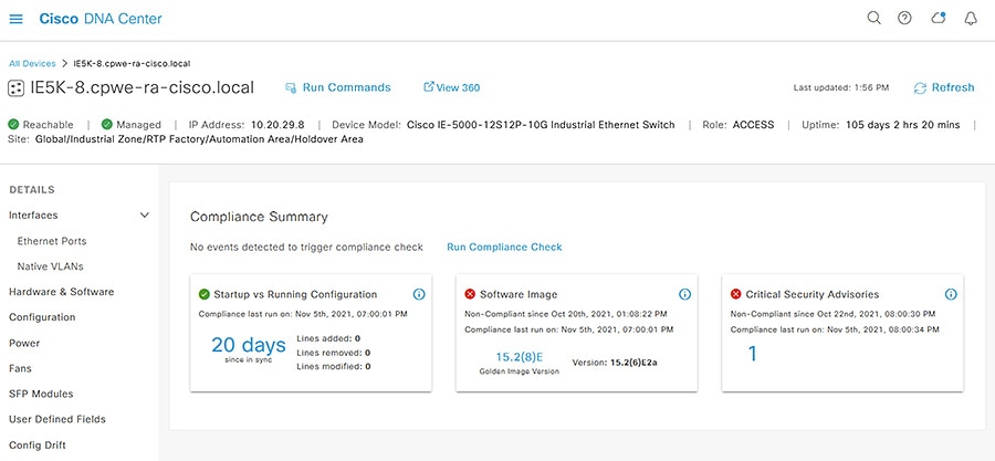
Clicking on the compliance issue in question will provide further details. If Software image or Critical Security Advisories are out of compliance, typically a software upgrade will address the issue and can be initiated through Inventory. If Startup vs Running Configuration is out of compliance, you have the option to click the Sync Device Config from the details page.
Device Replacement Workflow
In the event that a device is in need of replacement, Cisco DNA Center Inventory will allow you to mark the device for replacement in preparation for the Replace Device workflow. Cisco DNA Center will automatically configure a DHCP server on a neighboring device to aid the process of replacement. To mark a faulty device for replacement, do the following:
1.![]() From the Cisco DNA Center web interface, navigate to Provision > Network Devices > Inventory.
From the Cisco DNA Center web interface, navigate to Provision > Network Devices > Inventory.
2.![]() From the left Hierarchy, choose the Site with the device to be upgraded.
From the left Hierarchy, choose the Site with the device to be upgraded.
3.![]() Check the checkbox next to the device to be upgraded and from the Actions drop-down list choose Device Replacement > Mark for Replacement.
Check the checkbox next to the device to be upgraded and from the Actions drop-down list choose Device Replacement > Mark for Replacement.
The Replace Device workflow automatically provisions the new device with the last retrieved full configuration of the faulty device as well as adding the new device to Inventory. In addition, the workflow will update the software image to that of the faulty device (which will cause a momentary communication disruption on the new device). The new device being used for replacement must have the exact same product ID as the faulty device and the uplink interface should be the same to avoid communication disruption. The process is as follows:
1.![]() Connect the new device to the network and allow the Cisco DNA Center PnP process to discover the device (no need to claim the device). See the Appendix for notes on PnP network preparation.
Connect the new device to the network and allow the Cisco DNA Center PnP process to discover the device (no need to claim the device). See the Appendix for notes on PnP network preparation.
2.![]() From the Cisco DNA Center web interface, navigate to Workflows.
From the Cisco DNA Center web interface, navigate to Workflows.
3.![]() Click the Replace Device button, then click the Let’s Do it button.
Click the Replace Device button, then click the Let’s Do it button.
4.![]() On the Choose Device Type page, click the appropriate radio button for the device being replaced, then click the Next button.
On the Choose Device Type page, click the appropriate radio button for the device being replaced, then click the Next button.
5.![]() On the Choose Site page, choose the appropriate Site from the hierarchy for the faulty device, then click the Next button.
On the Choose Site page, choose the appropriate Site from the hierarchy for the faulty device, then click the Next button.
6.![]() On the Choose Faulty Device page, click the radio button of the faulty device, then click the Next button.
On the Choose Faulty Device page, click the radio button of the faulty device, then click the Next button.
7.![]() Under Available Replacement Devices, click the radio button of the new device, then click the Next button.
Under Available Replacement Devices, click the radio button of the new device, then click the Next button.
8.![]() On the Schedule Replacement page, click the Now radio button (if scheduling the replacement for a future date and time, click the Later radio button and specify the date and time). Click the Next button.
On the Schedule Replacement page, click the Now radio button (if scheduling the replacement for a future date and time, click the Later radio button and specify the date and time). Click the Next button.
9.![]() On the Summary page, review the details. Click the Replace button.
On the Summary page, review the details. Click the Replace button.
Note: As of Cisco DNA Center release 2.2.3.3, there is an issue with upgrading devices during the remediation process if they are currently running a.tar software image (instead of.bin).
Assurance
Overview
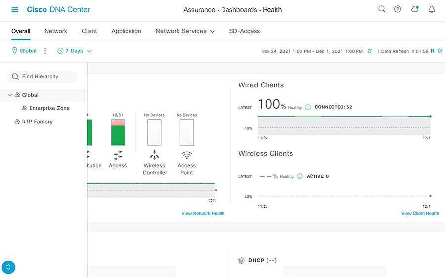
Cisco DNA Assurance provides a wealth of information to monitor the status and health of devices and endpoints. The telemetry data is collected in intervals after assigning a device to a Site and the device will send SNMP traps to Cisco DNA Center as events occur. Note that primarily only syslog levels of Emergency, Alert, and Critical are sent by default (see https://www.cisco.com/c/en/us/td/docs/cloud-systems-management/network-automation-and-management/dna-center-assurance/2-2-3/b_cisco_dna_assurance_2_2_3_ug/b_cisco_dna_assurance_2_2_2_ug_chapter_0110.html?bookSearch=true#reference_rxn_ntr_rgb). The Assurance health dashboard on the Cisco DNA Center web interface (Assurance > Dashboard > Health) gives an overview of issues and device health.
Note: The Health Dashboard displays the Global Site by default. The scope of the information displayed can be changed to Area or Building by clicking the Global link.
Figure 11 Cisco DNA Center Health Dashboard
Network and Client Health Status
Cisco DNA Center gives distinct consideration to network device and client monitoring. Under Assurance > Dashboards > Health > Network, you can see an overview of all managed devices and on the Network Devices pane, you can filter the list to view details for a specific device.Click the link in the Device Name column to open the Device 360 details of that device. The Device 360 page gives time-based details about the device health, including:
■![]() Device Details —Model, IP address, uptime, software version, and so on
Device Details —Model, IP address, uptime, software version, and so on
■![]() Issues —Cisco DNA Center has a standardized list of issues of varying priority, which can be tuned to meet the needs of your environment. Issues are generated from telemetry data.
Issues —Cisco DNA Center has a standardized list of issues of varying priority, which can be tuned to meet the needs of your environment. Issues are generated from telemetry data.
■![]() Physical Neighbor Topology —A miniature topology view of the device showing connection(s) to other device(s), highlighting link and device health in the graphic
Physical Neighbor Topology —A miniature topology view of the device showing connection(s) to other device(s), highlighting link and device health in the graphic
■![]() Event Viewer —SNMP trap messages sent from the device to Cisco DNA Center
Event Viewer —SNMP trap messages sent from the device to Cisco DNA Center
For clients, navigate to Assurance > Dashboards > Health > Client to view the Client 360 dashboard. Similar to network devices, Cisco DNA Center highlights issues and health of endpoints over time. On the Client Devices pane, click the link in the Identifier column to open the Client 360 page for the endpoint. The Client 360 page gives time-based details about endpoint health, including:
■![]() Client Details —MAC address, IP address, connection status, and so on.
Client Details —MAC address, IP address, connection status, and so on.
■![]() Issues —The client issues stem from the associated network device for the endpoint but are specific to the health of the endpoint communications.
Issues —The client issues stem from the associated network device for the endpoint but are specific to the health of the endpoint communications.
■![]() Onboarding —A graphic displaying the endpoint and network device connection health
Onboarding —A graphic displaying the endpoint and network device connection health
■![]() Event Viewer —SNMP trap messages sent from the network device to Cisco DNA Center
Event Viewer —SNMP trap messages sent from the network device to Cisco DNA Center
■![]() Path Trace —This feature is particularly useful in troubleshooting communication between the endpoint and another entity on the network. It checks the network between the two entities to determine if there is any cause for disruption.
Path Trace —This feature is particularly useful in troubleshooting communication between the endpoint and another entity on the network. It checks the network between the two entities to determine if there is any cause for disruption.
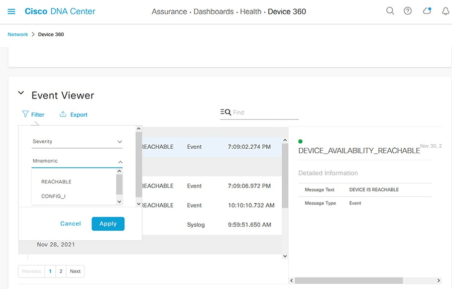
The time frame of the Device and Client 360 information can be changed to give administrators a historical look back at events. Click the clock link at the top left of the Device 360 or Client 360 page to adjust the time setting. To change Issue thresholds to suit your environment, navigate to Assurance > Manage > Issue Settings. In addition, the Event Viewer also has a Filter link to narrow down the events displayed for network devices or clients.
Figure 12 Cisco DNA Center Assurance Event Viewer
Issue Troubleshooting Example
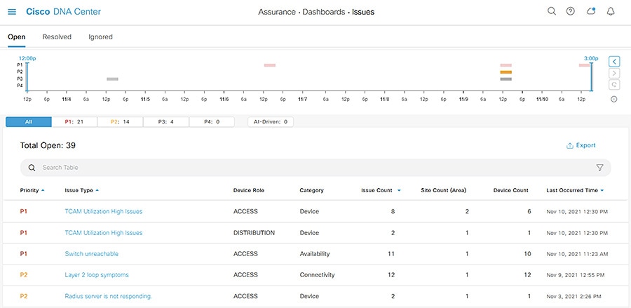
A consolidated list of issues can be found at Assurance > Dashboards > Issues and by navigating through the Issues pages Cisco DNA Center can help provide root cause analysis. Here is an example of using Cisco DNA Center Issues to troubleshoot a device problem.
1.![]() From the Assurance > Dashboards > Issues page, click the Layer 2 loop symptoms link under the Issue Type column.
From the Assurance > Dashboards > Issues page, click the Layer 2 loop symptoms link under the Issue Type column.
Figure 13 Cisco DNA Center Issues Dashboard
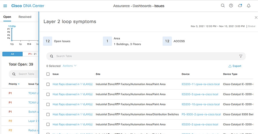
2.![]() The Layer 2 loop symptoms slide-in pane displays all associated issues per device. Click the Host flaps observed in 1 VLAN(s) link under the Issues column for a device.
The Layer 2 loop symptoms slide-in pane displays all associated issues per device. Click the Host flaps observed in 1 VLAN(s) link under the Issues column for a device.
Figure 14 Cisco DNA Center Issues—Layer 2 Loop Symptoms
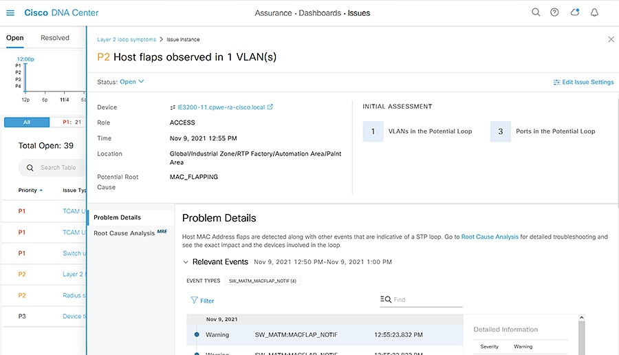
3.![]() The Issue Instance slide-in pane will display details about the occurrence of the issue including time and associated events.
The Issue Instance slide-in pane will display details about the occurrence of the issue including time and associated events.
Figure 15 Cisco DNA Center Issues—Host Flaps
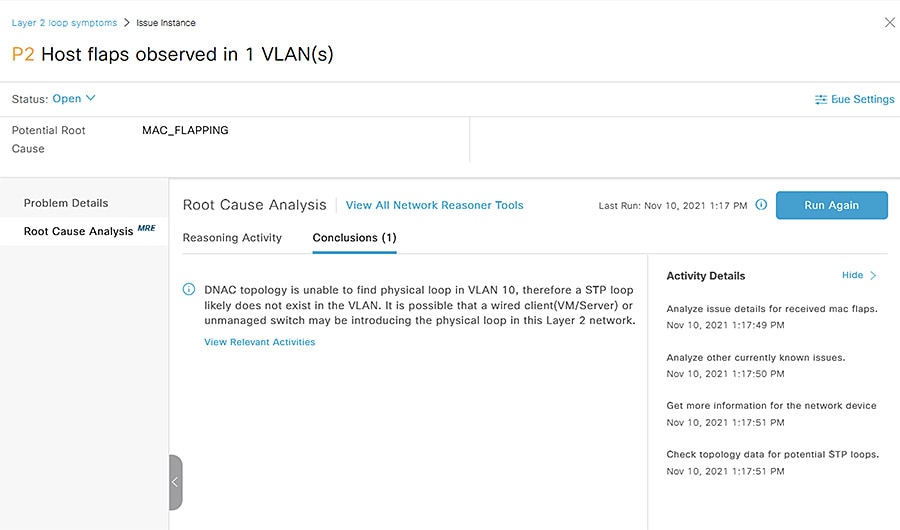
4.![]() Click the Root Cause Analysis tab on the left side bar and click the Run Machine Reasoning button. Cisco DNA Center will run an automated analysis of telemetry data to help determine issue cause and suggest remediation. Click the View Details button when it finishes.
Click the Root Cause Analysis tab on the left side bar and click the Run Machine Reasoning button. Cisco DNA Center will run an automated analysis of telemetry data to help determine issue cause and suggest remediation. Click the View Details button when it finishes.
Figure 16 Cisco DNA Center MRE
Security
Cisco DNA Center
For configuring Cisco DNA Center in a secure manner, refer to the Cisco DNA Center Security Best Practices Guide:
https://www.cisco.com/c/en/us/td/docs/cloud-systems-management/network-automation-and-management/dna-center/hardening_guide/b_dnac_security_best_practices_guide.html.
Industrial Automation Network Infrastructure
Cisco DNA Center can help manage the security of your network infrastructure with device configuration as well as applying network controls through the integration with Cisco ISE. The process is as follows:
1.![]() Connect Cisco DNA Center to ISE. Note that ISE can also be integrated with Cisco Cyber Vision to provide context for profiling industrial endpoints.
Connect Cisco DNA Center to ISE. Note that ISE can also be integrated with Cisco Cyber Vision to provide context for profiling industrial endpoints.
2.![]() Define SGTs and TrustSec policy in Cisco DNA Center.
Define SGTs and TrustSec policy in Cisco DNA Center.
3.![]() Define Profiles, and Authentication and Authorization policies in ISE.
Define Profiles, and Authentication and Authorization policies in ISE.
4.![]() Update Network Settings and Telemetry in Cisco DNA Center for all desired Sites to include AAA and IP Device Tracking and update necessary templates for additional TrustSec settings (interface configuration, SXP, enforcement, and so on).
Update Network Settings and Telemetry in Cisco DNA Center for all desired Sites to include AAA and IP Device Tracking and update necessary templates for additional TrustSec settings (interface configuration, SXP, enforcement, and so on).
5.![]() Send NetFlow to Cisco DNA Center (configuration pushed through Templates).
Send NetFlow to Cisco DNA Center (configuration pushed through Templates).
6.![]() Provision devices to apply the configurations and establish device communication with ISE, using AAA in Network Settings as well as additional template configurations.
Provision devices to apply the configurations and establish device communication with ISE, using AAA in Network Settings as well as additional template configurations.
For a full overview of the ISE and TrustSec implementation and recommendations in the Industrial Automation architecture, refer to the Industrial Automation Design Guide:
https://www.cisco.com/c/en/us/td/docs/solutions/Verticals/Industrial_Automation/IA_Horizontal/DG/Industrial-AutomationDG.html.
Cisco DNA Center and ISE
Cisco DNA Center integrates with Cisco ISE to establish unified environment tracking and control. When provisioning a device through Cisco DNA Center, AAA and RADIUS can be added to the Site’s network settings to automatically configure the necessary features for the device to communicate with Cisco ISE. IP device tracking can be enabled in Telemetry settings as well to track endpoint IP address to SGT bindings (see Network Settings). In addition, Cisco DNA Center will populate the network device database in ISE with the new device to establish the communication. Further configuration for AAA, such as policy maps and interface configurations, can be done through Day-N templates. See the Appendix for an example TrustSec template configuration for an IA architecture.
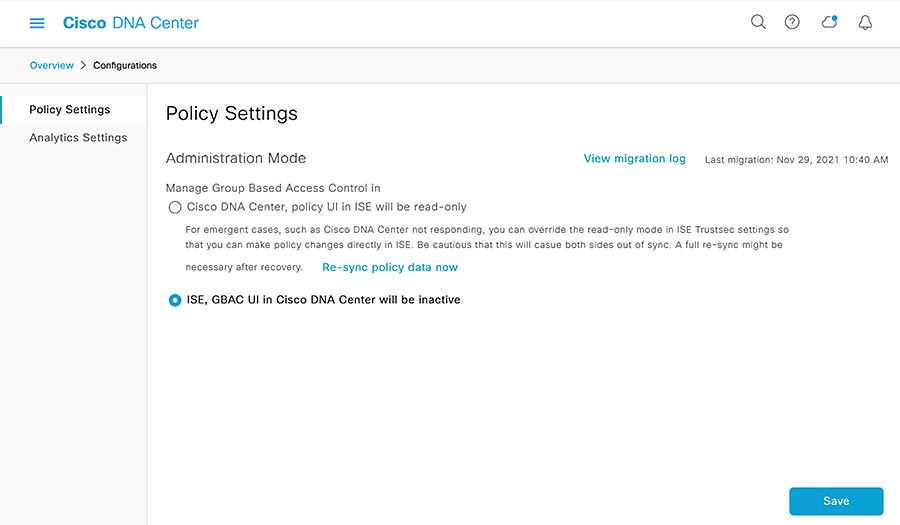
After integrating with ISE, it is recommended to use Cisco DNA Center as the TrustSec authority. The TrustSec policy matrix and SGT scheme are created and managed from Cisco DNA Center and the updates are automatically communicated to ISE, however ISE will maintain the profiling, authentication, and authorization policies. For existing ISE deployments, Cisco DNA Center will read the TrustSec configurations from ISE and management can be done from Cisco DNA Center. Note that Cisco DNA Center does not support multiple TrustSec matrices and if necessary TrustSec can be managed by ISE instead of Cisco DNA Center.
The authority can be changed by navigating to Policy > Group-Based Access Control and clicking the Configuration link.
Figure 17 Cisco DNA Center Policy Settings
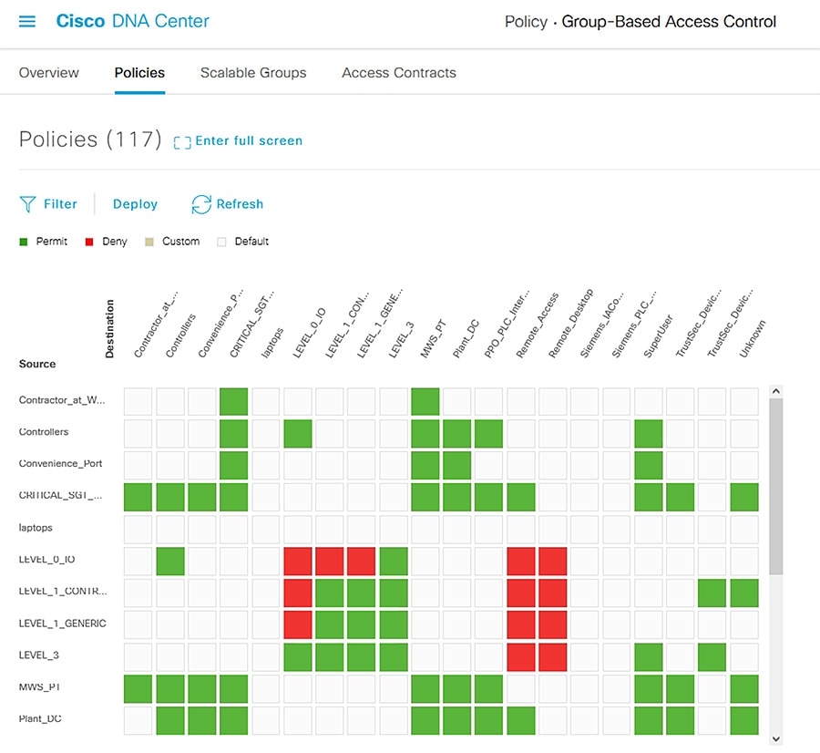
After creating the SGTs in Cisco DNA Center, the policy matrix can be updated to suit the enforcement intent. To make changes to the TrustSec policy matrix in DNA Center, do the following:
1.![]() From the Cisco DNA Center web interface, navigate to Policy > Group-Based Access Control.
From the Cisco DNA Center web interface, navigate to Policy > Group-Based Access Control.
3.![]() Click the square of the source and destination pair for which there needs to be a permit or deny contract.
Click the square of the source and destination pair for which there needs to be a permit or deny contract.
4.![]() On the Create Policy slide-in pane, click the Change Contract link and choose the appropriate option (Permit IP, Deny IP, and so on). Click the Change button.
On the Create Policy slide-in pane, click the Change Contract link and choose the appropriate option (Permit IP, Deny IP, and so on). Click the Change button.
5.![]() Click the Deploy link at the top of the matrix.
Click the Deploy link at the top of the matrix.
Figure 18 Cisco DNA Center TrustSec Policy Matrix
Policy Analytics
Cisco DNA Center can help track communication flows from devices with NetFlow and TrustSec, giving administrators details about status and health to maintain accurate configuration and security posture.
After configuring Cisco DNA Center as a NetFlow collector through templates, communication flows can be reviewed by doing the following:
1.![]() From the Cisco DNA Center web interface, navigate to Policy > Group-Based Access Control.
From the Cisco DNA Center web interface, navigate to Policy > Group-Based Access Control.
2.![]() Under View traffic for…, click the Scalable Groups button.
Under View traffic for…, click the Scalable Groups button.
3.![]() The Explore Scalable Groups graphic shows SGT to SGT communications. Click a connection line to display further details.
The Explore Scalable Groups graphic shows SGT to SGT communications. Click a connection line to display further details.
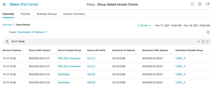
4.![]() Alternatively, from the Policy > Group-Based Access Control page enter the IP or MAC address of a device in the search bar and choose either the Source IP Address or Destination IP Address option from the drop-down list, then press Return. The Search Results table will show communication details for the device in question. Click the 24 hrs button to change the date or time to view additional results.
Alternatively, from the Policy > Group-Based Access Control page enter the IP or MAC address of a device in the search bar and choose either the Source IP Address or Destination IP Address option from the drop-down list, then press Return. The Search Results table will show communication details for the device in question. Click the 24 hrs button to change the date or time to view additional results.
Figure 19 Cisco DNA Center Group-Based Access Control
Endpoint Analytics
In addition, endpoint details are monitored through Cisco DNA Center if the endpoint is connected to a switch managed by Cisco DNA Center, authenticated, and has a live session with ISE. To view endpoint analytics, do the following:
1.![]() From the Cisco DNA Center web interface, navigate to Policy > AI Endpoint Analytics.
From the Cisco DNA Center web interface, navigate to Policy > AI Endpoint Analytics.
2.![]() Click the Endpoint Inventory tab.
Click the Endpoint Inventory tab.
3.![]() Click the link in the MAC Address column to view further details about the endpoint.
Click the link in the MAC Address column to view further details about the endpoint.
Additional Tools and Troubleshooting
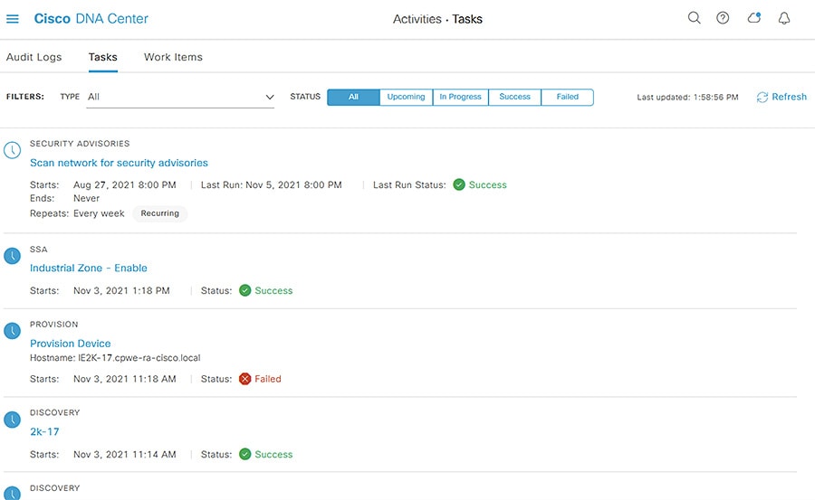
Audit Logs and Tasks
Cisco DNA Center tracks many activities done in the tool. Audit Logs provide details such as user logins, data purges, device name changes, and so on. The Tasks tool shows real-time status details for activities launched by users, such as provisioning, software update, replacement workflow, and so on. From the Cisco DNA Center web interface, navigate to Activities from the main menu to view Audit Logs and Tasks.
Figure 20 Cisco DNA Center Audit Logs
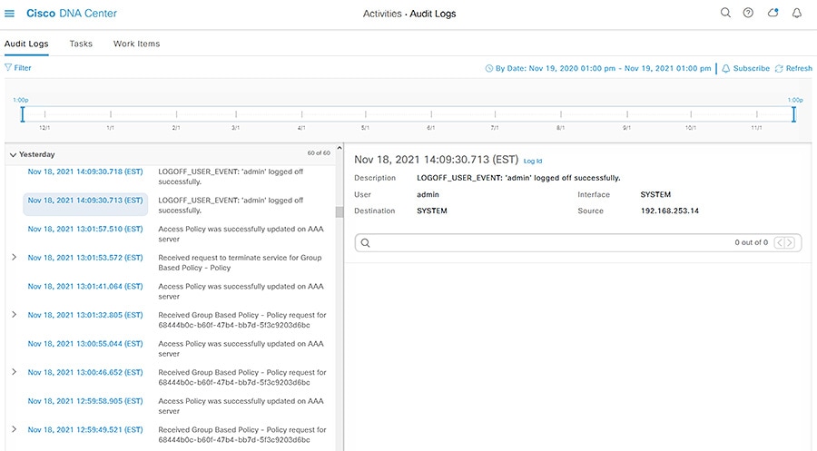
Figure 21 Cisco DNA Center Tasks
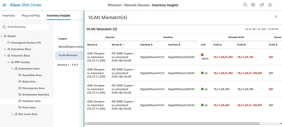
Inventory Insights
Because Cisco DNA Center is collecting real time data about devices and their activity, it can help highlight potential issues. By navigating to Provision > Network Devices > Inventory Insights, you can see a consolidated view potential issues and remediation suggestions on a per-Site basis.
Figure 22 Cisco DNA Center Inventory Insights
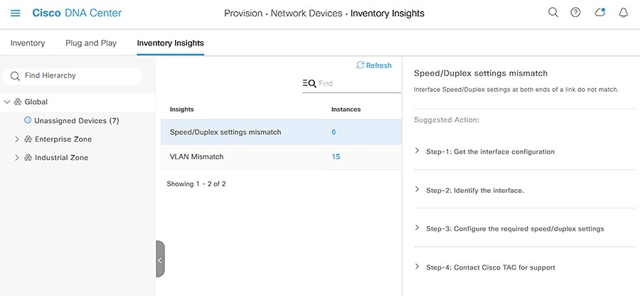
Figure 23 Cisco DNA Center Inventory Insights Details
Command Runner
Cisco DNA Center provides a quick way to run commands on a device directly From the Cisco DNA Center web interface, which can be helpful for verifying configuration without having to access the device directly. To launch Command Runner, do the following:
1.![]() From the Cisco DNA Center web interface, navigate to Provision > Network Devices > Inventory.
From the Cisco DNA Center web interface, navigate to Provision > Network Devices > Inventory.
2.![]() From the left Hierarchy, choose the Site for the device in question.
From the left Hierarchy, choose the Site for the device in question.
3.![]() Click the link for the device under the Device Name column.
Click the link for the device under the Device Name column.
4.![]() On the Device page, click the Run Commands link.
On the Device page, click the Run Commands link.
Note: Only User EXEC level commands are accepted in Command Runner.
License Manager
Cisco DNA Center keeps track of the licensing for the managed devices, which can help administrators verify compliance and troubleshoot issues pertaining to inadequate licensing. Navigate to Tools > License Manager to view the licensing details.
Security Advisories
Because Cisco DNA Center communicates with Cisco.com directly for software image management, it has an up-to-date database of publicized security advisories associated to specific software images. Tools > Security Advisories displays a table of advisory IDs and lists any managed devices that are affected.
Reports
Cisco DNA Center has specialized reports to organize its data into useful insights. Navigate to Reports > Report Templates to browse the available reports that can be generated into various formats such as PDF, CSV, JSON, and so on.
System 360
Cisco DNA Center provides its own health status and details in a unique dashboard, which can help provide insight into software upkeep, integration health, and so on. Navigate to System > System 360 to view the System Management dashboard.
Appendix
Plug and Play Network Preparation
When adding a new switch to the network, there are some configuration prerequisites for Plug and Play to be able to run successfully, including:
■![]() PNP VLAN—The upstream switch needs to have the Plug and Play VLAN specified.
PNP VLAN—The upstream switch needs to have the Plug and Play VLAN specified.
■![]() Interface configuration—The interface to which the new switch is connected needs to be configured with the PNP startup VLAN. For example:
Interface configuration—The interface to which the new switch is connected needs to be configured with the PNP startup VLAN. For example:
■![]() DHCP for the PNP switch—The switch being added to the network needs to receive a DHCP IP address for communication with Cisco DNA Center. On the DHCP server, configure a DHCP pool, such as:
DHCP for the PNP switch—The switch being added to the network needs to receive a DHCP IP address for communication with Cisco DNA Center. On the DHCP server, configure a DHCP pool, such as:
The DHCP option 43 string has the following components, delimited by semi-colons:
–![]() 5A1N;—Specifies the DHCP sub-option for PnP, active operation, version 1, no debug information. It is not necessary to change this part of the string.
5A1N;—Specifies the DHCP sub-option for PnP, active operation, version 1, no debug information. It is not necessary to change this part of the string.
–![]() B2;—IP address type. B2 stands for IPv4. B1 should be used for hostname.
B2;—IP address type. B2 stands for IPv4. B1 should be used for hostname.
–![]() Ixxx.xxx.xxx.xxx;—IP address or hostname of the Cisco DNA Center controller (following a capital letter i). In this example, the IP address is 172.19.45.222.
Ixxx.xxx.xxx.xxx;—IP address or hostname of the Cisco DNA Center controller (following a capital letter i). In this example, the IP address is 172.19.45.222.
–![]() Jxxxx—Port number to use to connect to the Cisco DNA Center controller. In this example, the port number is 80. The default is port 80 for HTTP and port 443 for HTTPS.
Jxxxx—Port number to use to connect to the Cisco DNA Center controller. In this example, the port number is 80. The default is port 80 for HTTP and port 443 for HTTPS.
–![]() K4;—Transport protocol to be used between the device and the controller. Use K4 for HTTP (default) or K5 for HTTPS.
K4;—Transport protocol to be used between the device and the controller. Use K4 for HTTP (default) or K5 for HTTPS.
There is a DNS discovery option similar to DHCP which requires the following:
■![]() Domain name option configured on DHCP server.
Domain name option configured on DHCP server.
■![]() DNS server option configured on DHCP server.
DNS server option configured on DHCP server.
■![]() PnP server (Cisco DNA Center) resolves to PnP deployment server IP address in DNS.
PnP server (Cisco DNA Center) resolves to PnP deployment server IP address in DNS.
■![]() IP helper address should be configured on the distribution switch.
IP helper address should be configured on the distribution switch.
Offline Discovery Example Switch Configuration
Cisco DNA Center Template Examples for the Industrial Automation Network
Any example provided is for reference only and should be adapted to the customer environment. Examples are based on the Cisco IE3400 switch.
Onboarding Template
For onboarding, the main goal is to get the device online with a base configuration; this is the initial configuration pushed out as part of the PnP process.
The following is an example for a device connected via EtherChannel, requires a native VLAN different than 1, requires CTS inline tagging, and requires a static IP address.
Day-N Templates
For Day-N configuration, the main goal is to complete the device configuration so it is ready for production. The format can be a standard template or a composite template.
Example for General Configuration on the Cisco IE3400 Switch
Example for Interface Configuration
See tip in binding to define variables. This example shows how to configure interfaces using foreach loops:
Example for Cyber Vision Sensor Configuration
This example only configures iox if required by the user, after it waits for iox to start.
Example for TrustSec Configuration
Template Tips
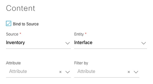
1.![]() Source-binding—Bind the details Cisco DNA Center has learned about the device (such as interface names) to a variable in the template.
Source-binding—Bind the details Cisco DNA Center has learned about the device (such as interface names) to a variable in the template.
Figure 24 Cisco DNA Center Template Editor—1
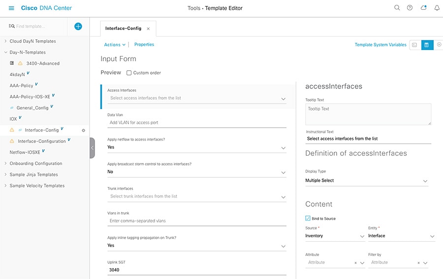
Figure 25 Cisco DNA Center Template Editor—2
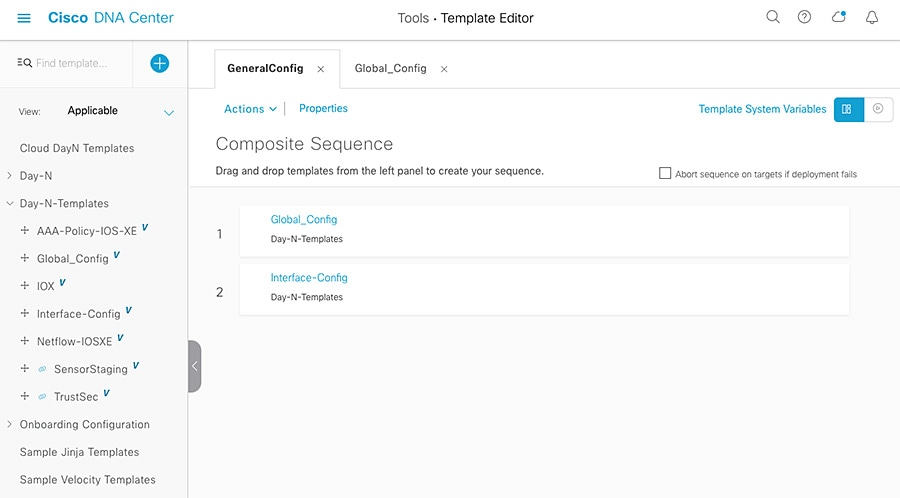
2.![]() Composite templates can be used to guarantee execution order.
Composite templates can be used to guarantee execution order.
Figure 26 Cisco DNA Center Composite Templates
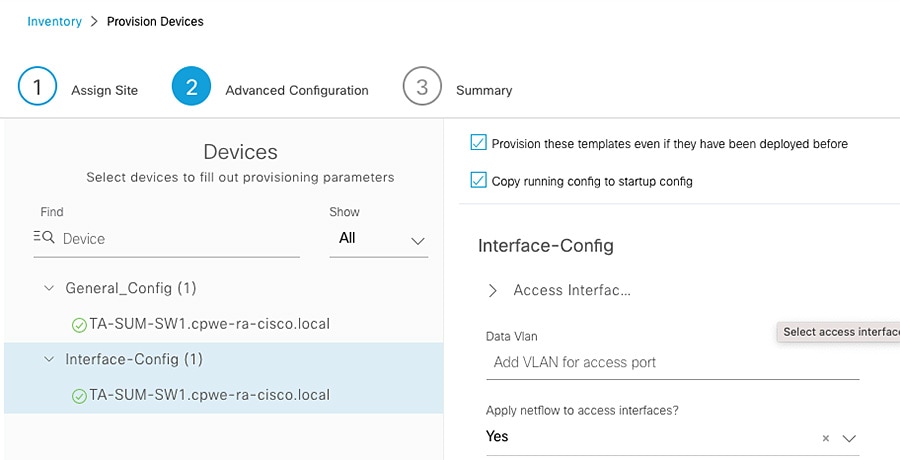
3.![]() Options—Check the Provisioning of these templates even if they have been deployed before and Copy running config to startup config checkboxes.
Options—Check the Provisioning of these templates even if they have been deployed before and Copy running config to startup config checkboxes.
Figure 27 Cisco DNA Center Provisioning with Templates—1
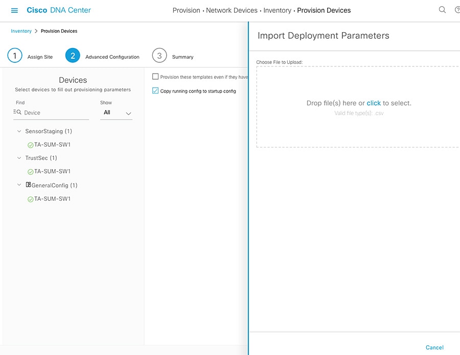
Export file first to download sample, then fill and import. Re-use as needed.
Figure 28 Cisco DNA Center Provisioning with Templates—2
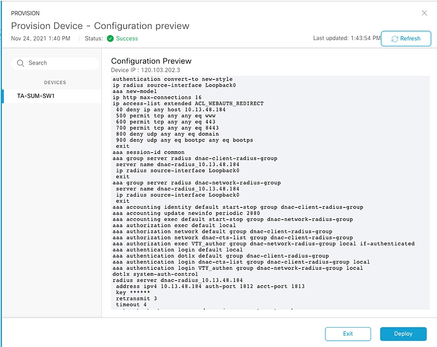
5.![]() Generate a template preview.
Generate a template preview.
Figure 29 Cisco DNA Center Provisioning Preview—1
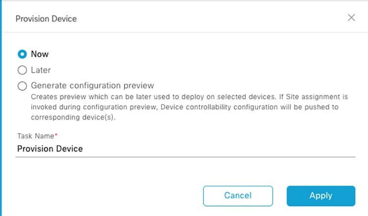
Figure 30 Cisco DNA Center Provisioning Preview—2
6.![]() Use tags to apply templates to selected devices.
Use tags to apply templates to selected devices.
Figure 31 Cisco DNA Center Templates with Tags—1
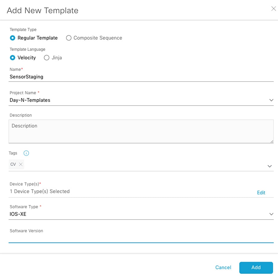
Figure 32 Cisco DNA Center Templates with Tags—2
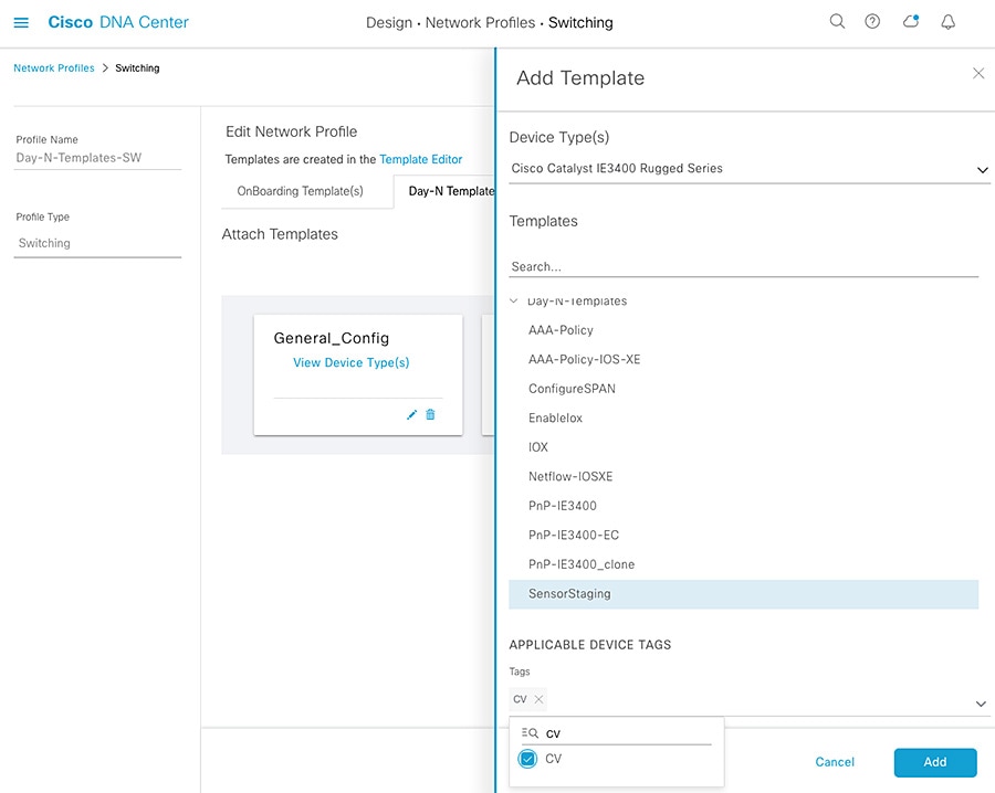
Figure 33 Cisco DNA Center Inventory—Tagged Devices
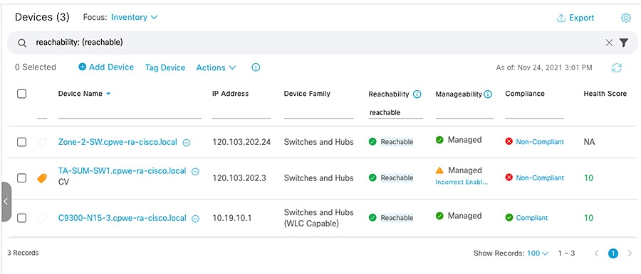
Figure 34 Cisco DNA Center Provisioning Templates per Tag
 Feedback