Industrial Automation - Reliable Wireless for Factory AGV/AMR Environments
Bias-Free Language
The documentation set for this product strives to use bias-free language. For the purposes of this documentation set, bias-free is defined as language that does not imply discrimination based on age, disability, gender, racial identity, ethnic identity, sexual orientation, socioeconomic status, and intersectionality. Exceptions may be present in the documentation due to language that is hardcoded in the user interfaces of the product software, language used based on RFP documentation, or language that is used by a referenced third-party product. Learn more about how Cisco is using Inclusive Language.
- Updated:
- June 2, 2022
Chapter: Industrial Automation - Reliable Wireless for Factory AGV/AMR Environments
- CURWB for AGVs/AMRs in Factories and Warehouses
- AGV/AMR System Overview
- AGV/AMR Systems Deliver Value
- Automated Guided Vehicles (AGVs)
- Autonomous Mobile Robots (AMRs)
- AGV/AMR Communication Requirements
- Industrial Safety Protocols
- Industrial Safety Protocols
- Common Industrial Protocol (CIP)
- PROFINET
- Network Requirements
- Wireless Network Requirements for AGVs/AMRs
- Challenges Supporting Real-Time Applications over Wireless
- CURWB Overview
- CURWB Network Design for AGV/AMR
- Wired and Wireless Network Components
- CURWB Gateway
- CURWB FM4500 Radio Unit
- CURWB FM3500 Endo Radio Unit
- RACER
- FM-Monitor
- FM-Monitor Dashboard
- FM-Monitor Table View
- CURWB - Terminology
- CURWB Network Design
- MTU Considerations
- Spanning Tree Protocol (STP)
- AutoTap
- Network Time Protocol (NTP)
- CURWB Fluidity Advanced - Large Network Optimization
- Fluidity Advanced Handoff Tuning for Vehicle Radio Units
- QoS Implementation on CURWB Radios
- CURWB QoS - MPLS Experimental Bits (EXP)
- Security - AES Encryption
- CURWB L2 Fluidity
- CURWB L3 Fluidity
- CURWB Single Frequency Design
- CURWB Multi Frequency Design
- Static Multi-Frequency Design
- Dynamic Multi-Frequency Design
- CURWB System Design Considerations
- CIP Safety over Wireless - Design Considerations
- PROFINET over Wireless – Design Considerations
- L2 Fluidity Architecture for Factory AGV/AMR Using CIP Safety
- Cell/Area Zone
- Manufacturing Zone
- CURWB L2 Fluidity Architecture
- L3 Fluidity Architecture for Factory AGV/AMR Using CIP Safety
- High Availability (HA)
- TITAN Fast Convergence and High-Availability Plug-in
- Gratuitous ARP (GARP)
- Redundancy at the Distribution/Core Layer
- CURWB Access Layer - Fast Convergence on Failure
- On-board Radio Redundancy - Failover and Recovery
- CURWB Network Deployment Guidance
- CIP/PROFINET Support on CURWB
- Enabling QOS for CIP Traffic
- Configuring PROFINET on Cisco IE Switches
- Enabling QoS on CURWB Radios
- Tweaking the Packet Retry Delay and Fallback values on CURWB
- Key Recommendations for a CIP Safety deployment
- Perform an RF Site Survey
- Configuration and Provisioning Best Practices
- Deployment Guidance and Best Practices
- Best Practices for Rollout
- CURWB Tools for Live RF Analysis and Troubleshooting
Industrial Automation - Reliable Wireless for Factory AGV/AMR Environments
CURWB for AGVs/AMRs in Factories and Warehouses
The trending digitization in factories and warehouses requires an increasing number of connected devices introduced into industrial operations at a rapid pace. Concurrently, wireless connectivity has improved enabling many mobile applications within production environments. A key area of improvement for production systems is reliable wireless that enables safety and control of mobile systems, such as Automated Guided Vehicles (AGVs) and Autonomous Mobile Robots (AMRs). Industrial control and automation planners are embracing the benefits of mobility and are integrating wireless technology into system design. This Cisco Reference Design (CRD) document provides design guidance and implementation best practices for integrating a Cisco Ultra Reliable Wireless Backhaul (CURWB) mobility solution to support operations in Factories and Warehouses.
Topics described in this document are listed below.
■![]() Description of Automated Guided Vehicles (AGVs) and Autonomous Mobile Robots (AMRs) system use cases
Description of Automated Guided Vehicles (AGVs) and Autonomous Mobile Robots (AMRs) system use cases
■![]() Advantages of using AGV/AMR systems in factories and warehouses
Advantages of using AGV/AMR systems in factories and warehouses
■![]() Control protocols used to operate and maintain safety of AGVs/AGRs
Control protocols used to operate and maintain safety of AGVs/AGRs
■![]() Network Requirements for the AGV/AMR application
Network Requirements for the AGV/AMR application
■![]() Design Considerations for supporting CIP and PROFINET
Design Considerations for supporting CIP and PROFINET
■![]() An overview of the Cisco Ultra-Reliable Wireless Backhaul (CURWB) technology
An overview of the Cisco Ultra-Reliable Wireless Backhaul (CURWB) technology
■![]() CURWB features around Mobility and support for Real-Time Latency-Sensitive applications
CURWB features around Mobility and support for Real-Time Latency-Sensitive applications
■![]() Why CURWB is best suited to address the requirements for the AGV/AMR application
Why CURWB is best suited to address the requirements for the AGV/AMR application
CURWB Network Design for AGV/AMR
■![]() Wired and Wireless Network components
Wired and Wireless Network components
■![]() CURWB Network Design Elements
CURWB Network Design Elements
■![]() CURWB L2 and L3 Fluidity Mobility Architecture Overview
CURWB L2 and L3 Fluidity Mobility Architecture Overview
■![]() CURWB L2 Fluidity Architecture for Factory AGV/AMR application
CURWB L2 Fluidity Architecture for Factory AGV/AMR application
■![]() CURWB L3 Fluidity Architecture for Factory AGV/AMR application
CURWB L3 Fluidity Architecture for Factory AGV/AMR application
■![]() High-Availability, QoS, and Security
High-Availability, QoS, and Security
■![]() Network Design Considerations and Best Practices for AGV/AMR application
Network Design Considerations and Best Practices for AGV/AMR application
CURWB Deployment Guidance and Best-Practices
■![]() CURWB deployment guidance and best practices about RF Site Survey, Spectrum Analysis, RF Tuning, QoS, and Network Configurations
CURWB deployment guidance and best practices about RF Site Survey, Spectrum Analysis, RF Tuning, QoS, and Network Configurations
AGV/AMR System Overview
AGV/AMR Systems Deliver Value
Manufacturers are finding value deploying AGVs and AMRs to improve operational productivity and flexibility in the production environments. Logistics companies in many industries are investing in automated material handling systems with AGVs to improve operations and increase worker safety.
AGVs and AGRs move autonomously throughout production sites to independently fulfill various tasks or move products and parts through the system. This mobility is possible because of the advancement of reliable wireless communications.
Automated Guided Vehicles (AGVs)
AGVs are used to move product or components throughout a production facility. Typically an AGV solution comprises of a central control system, a navigation system, and multiple vehicles that move about the plant according to the needs of the operation. The vehicles are often customized to the needs of the operation.
AGVs communicate with the infrastructure about sensitive and time-critical information necessary for autonomous operation, such as receiving control commands. Any large network latency or long interruptions on the communication network can trigger AGV(s) to stop, leading to undesirable disruptions in the manufacturing process.
Autonomous Mobile Robots (AMRs)
Autonomous Mobile Robots (AMRs) are currently being introduced in many intralogistics operations, like manufacturing, warehousing, cross-docks, terminals, and hospitals. Its advanced hardware and control software allow autonomous operations in dynamic environments. Compared to an Automated Guided Vehicle (AGV) system in which a central unit takes control of scheduling, routing, and dispatching decisions for all AGVs, AMRs can communicate and negotiate independently with other resources like machines and systems and decentralize the decision-making process. Decentralized decision-making allows the system to react dynamically to changes in the system state and environment.
In contrast to an AGV, an AMR navigates via maps that its software constructs on-site or via pre-loaded facility drawings. The AMR uses data from cameras and built-in sensors and laser scanners as well as sophisticated software that enables it to detect its surroundings and choose the most efficient route to reach its intended destination. It works completely autonomously and if forklifts, pallets, people, or other obstacles occur in front of it, the AMR will safely maneuver around them, using the best alternative route. This optimizes productivity by ensuring that material flow stays on schedule.
An AMR only needs simple software adjustments to change its missions, so the same robot can perform a variety of different tasks at different locations, automatically making adjustments to meet changing environments and production requirements. AMR tasks can be controlled via the robot interface or configured by fleet control software for multiple robots that automatically prioritizes orders and the robot that is best-suited for a given task based on position and availability. Once a mission is established, employees do not have to spend time coordinating the robots’ work, which allows them to focus on high-value work that contributes to company success.
The flexibility of AMRs is crucial for modern manufacturing environments that require agility and flexibility if there is a need for modifications to products or the production line. AMRs are highly adaptable for agile production in any size facility. If production cells are moved or new cells or processes are added, a new map of the building can be quickly and easily uploaded or the AMR can re-map onsite, so it can be used immediately for new tasks. This capability gives organizations full ownership of the robot and its functions.
Although an AMR consists of much more advanced technology than an AGV, it is typically a less-expensive solution. An AMR does not need wires, magnetic stripes, or other costly modifications to the building infrastructure so it is faster and less expensive to get AMRs up and running, and with no costly disruption to production in the process. Because AMRs can be deployed quickly and easily, they add new efficiencies almost immediately. With low initial costs and fast optimization of processes, they offer remarkably fast return on investment–often in less than six months
AGV/AMR Communication Requirements
AGVs and AGRs rely upon wireless communication with local, centralized applications for safety, control, guidance and optimization. This communication has to be reliable and fast to keep the AGVs and AGRs operational. This section discusses some of the key communication requirements of these applications that the wireless network must support.
Industrial Safety Protocols
One of the most critical applications for AGVs and AGRs are the safety applications that keep the personnel, product, and AGVs/AGRs from harm. This section explains key considerations of the two most commonly used industrial safety protocols for controlling AGVs/AGRs: the ODVA Common Industrial Protocol (CIP) Safety and PROFINET Profi-Safe. A high-level overview of the protocols is provided along with the protocol characteristics and wireless design considerations to support the protocol.
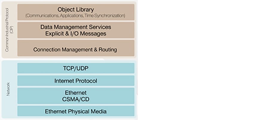
Common Industrial Protocol (CIP)
The Common Industrial Protocol (CIP) allows users to integrate automation applications - including control, safety, synchronization, and motion - across all aspects of the business. CIP is a media independent protocol using a producer-consumer communication model, and is a strictly object oriented protocol at the upper layers.
Each CIP object has attributes (data), services (commands), connections, and behaviors (relationship between attribute values and services). CIP includes an extensive object library to support general purpose network communications, network services such as file transfer, and typical automation functions such as analog and digital input/output devices, HMI, motion control and position feedback.
A key feature of CIP is that it defines two types of communication, or messages: explicit and implicit. Explicit messages are used for “as-needed” data (information) and are transmitted via TCP (transmission control protocol). Implicit messages are used for control data (inputs and outputs) — where high speed and low latency are important — and are transmitted via UDP (user datagram protocol). The UDP protocol allows messages to be sent in smaller packet sizes and makes it possible to use the producer-consumer model for these critical, implicit messages.
Industrial Safety Protocols
This section provides an overview of the two most commonly used industrial/industrial safety protocols in use: the Common Industrial Protocol (CIP) and PROFINET. A high-level overview of the protocols is provided along with the protocol characteristics and wireless design considerations to support the protocol.
Common Industrial Protocol (CIP)
The Common Industrial Protocol (CIP) allows users to integrate automation applications - including control, safety, synchronization, and motion - across all aspects of the business. CIP is a media independent protocol using a producer-consumer communication model, and is a strictly object oriented protocol at the upper layers.
Each CIP object has attributes (data), services (commands), connections, and behaviors (relationship between attribute values and services). CIP includes an extensive object library to support general purpose network communications, network services such as file transfer, and typical automation functions such as analog and digital input/output devices, HMI, motion control and position feedback.
A key feature of CIP is that it defines two types of communication, or messages: explicit and implicit. Explicit messages are used for “as-needed” data (information) and are transmitted via TCP (transmission control protocol). Implicit messages are used for control data (inputs and outputs) — where high speed and low latency are important — and are transmitted via UDP (user datagram protocol). The UDP protocol allows messages to be sent in smaller packet sizes and makes it possible to use the producer-consumer model for these critical, implicit messages.
CIP Safety
CIP Safety is an extension to the standard capabilities of CIP, and it has been certified for use in functional safety applications. Allen Bradley systems utilize GuardLogix programmable safety controllers and safety remote IO modules. CIP Safety devices are connected to the same Ethernet/IP network as the other machine devices, utilizing the same network. The CIP device is responsible for confirming the integrity of the data, and if an error occurs, it will go into a safe state. There is also a CIP Safety application layer that validates the integrity of the safety data transfers between the safety PLC and the CIP Safety device. There are time stamps and production identifier information that are contained in each packet to ensure that the data is from the expected device as well as within the time expected.
Figure 2 CIP Safety Communication Mechanics
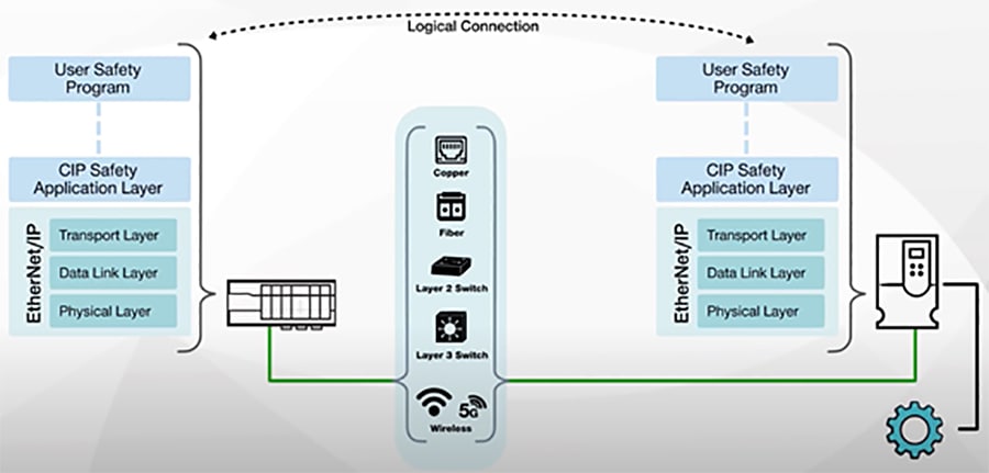
Figure 3 CIP Safety Application goes into Fail-Safe State if any one of the above failures occurs on the network
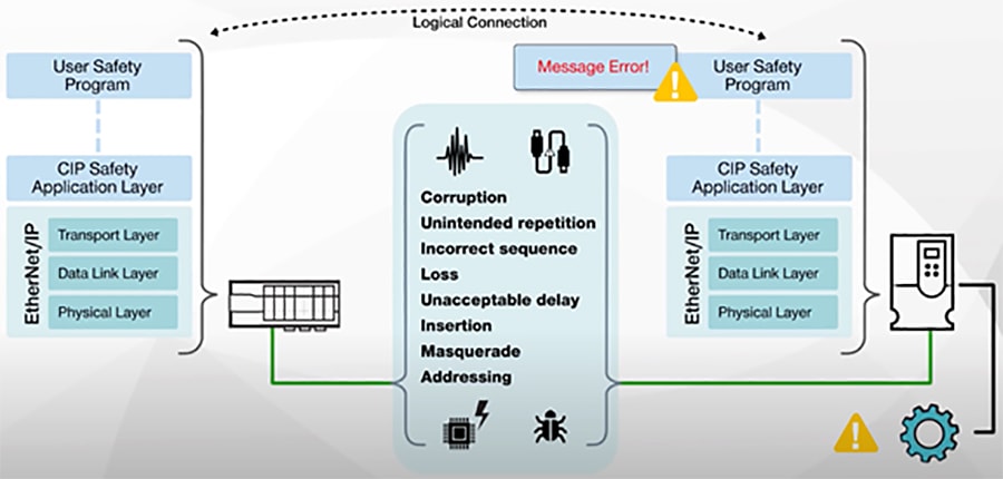
Figure 4 CIP Safety Application Layer Error Checking
To avoid the complexity and maintenance of designing a dedicated safety-rated network, IEC 61508 and IEC 61784-3 emphasize another option called “the black channel”. The black channel assumes that network is completely unreliable, so diagnostics must exist outside of the network infrastructure. This concept stipulates that if a safety communication protocol has enough error detection built into the protocol, it can be transmitted independently across different network types without degrading the integrity of the safety data. This can include traversing multiple network links and network segmentation techniques.
Figure 5 Routing of CIP Safety Traffic across the network
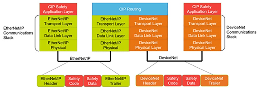
Figure 6 CIP Safety Traffic Through Multiple Layers of an EtherNet/IP Network
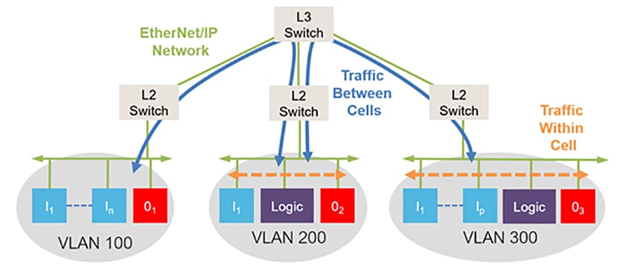
Only the safety data that is needed is routed to the required cell, which reduces the individual bandwidth requirements. The combination of fast responding local safety cells and the inter-cell routing of safety data allows users to create significantly larger and more complex safety applications with fast response times.
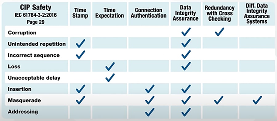
CIP Safety devices create a logical connection to each other, independent of the network technologies being used. In the devices, common errors are mitigated with various techniques, as described in IEC 61784-3-2. Time stamps are used with time expectation to detect if packets are lost, delayed, repeated, or transmitted out of order. Unique device identifiers are used to authenticate the communication between two safety devices. Additional diagnostics and checks are included to validate that the messages are not corrupted in transit and all these features are separate from standard communication methods.
When these mitigations are put together as CIP Safety, a single connection between two devices, wired or wireless, can be used for communications certified up to SIL 3 per IEC 61508 and up to Category 4/PLe per ISO 13849-1.
CIP Safety over wireless is heavily leveraged in several applications, including factory automation in production environments like those found in automotive assembly plants. In these plants, several different types of conveyance systems, such as AGVs, are used to move vehicles and parts throughout the production cells. In these systems, the auto manufacturers prioritize the safety of their employees, and the flexibility of the system for future enhancements. This creates the requirement for Functional Safety via CIP Safety, and the wireless link to enable it.
In a typical AGV deployment, there are several AGVs traveling hundreds of feet. Each AGV is outfitted with electronics including sensors for collision avoidance, location awareness, and safety, as well as drives for propulsion, I/O, and a safety controller such as a Compact GuardLogix®. This AGV system requires a wireless communication connection to the main safety controller, which may be a GuardLogix®. This main controller also serves as the traffic cop for the entire AGV application and thus the system requires control, safety, and diagnostic data to be transmitted wirelessly.
PROFINET
PROFINET is the PROFIBUS International (PI) industrial Ethernet standard designed for automation control communication over Ethernet-based infrastructure.
PROFINET devices may require different communication speeds depending on the type of automation process. The PROFINET protocol supports three communication classes, each with a different degree of time sensitivity. These are Non-real-time (NRT), Real-time (RT), and Isochronous Real-time (IRT) communication.
NRT, sometimes referred to as TCP/IP communication, is acyclic traffic such as sensory, diagnostic, or maintenance data transferred at best-effort speed. RT communication is cyclic traffic consisting of high-performance process data transmitted over standard networking infrastructure. IRT communication is the highest performing type of deterministic traffic within the PROFINET standard. However, this requires hardware-based bandwidth reservation and network-wide clock synchronization to function.
The PROFINET RT and IRT communication classes involve a cyclic data exchange over standard Ethernet and take place directly on Layer 2 without any TCP/IP overhead to minimize latency. This means that in an RT/IRT PROFINET environment, data frames are forwarded based on the devices′ MAC address. Therefore, it is essential that any underlying network infrastructure deployed to support RT or IRT PROFINET applications is fully Layer 2 transparent to all connected PROFINET devices.
The performance of PROFINET-based communication is limited to the performance ceiling of the underlying network infrastructure. To provide the flexibility to operate reliably over the different network infrastructure components, the cyclic data exchange rate for PROFINET RT communication can be customized to accommodate any infrastructure limitations or to suit the automation context.
In the example using the Siemens TIA Portal, the IO cycle > Update time parameter defines the communication update interval between the PROFINET IO controller and the IO devices. The IO cycle > Watchdog time parameter specifies the number of consecutive response failures before reporting a link failure which, depending on the process design, typically triggers the error handling or safe mode, halting the automation process.
PROFISAFE
PROFIsafe is an additional software layer that provides functional safety over the bus in PROFINET (or PROFIBUS) networks. PROFIsafe will take care of the functional safety portion of communications. It ensures the integrity of failsafe signals transmitted between safety devices and a safety controller meeting the relevant safety standards for industrial networks (up to SIL3 according to IEC 61508 / IEC 62061, or Category 4 according to EN 954-1, or PL “e” according to ISO 13849-1).
Figure 7 PROFISAFE Protocol Stack
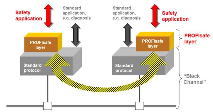
The diagram above illustrates the difference between PROFIsafe and PROFINET in terms of roles. PROFINET is the overall communication protocol. PROFIsafe is an additional layer that fulfills the functional safety requirements of the application.
PROFIsafe ensures the integrity of failsafe signals transmitted between safety devices and a safety controller meeting the relevant safety standards for Industrial networks. It is even approved for wireless transmission channels such as WLAN and Bluetooth. Therefore, PROFINET users can utilize PROFIsafe for functional safety and transmit safety messages over their standard network, which can include WLAN or Bluetooth connections.
Network Requirements
The internal transport systems for routing and supervising AGVs often use navigation systems. However, precise positioning is required at all times, for e.g., an AGV that is moving in an environment with other AGVs or other moving elements such as people. AGV should not only avoid obstacles but do it optimally. Avoiding means not only stopping but trying to predict them and find an alternative, safe route. Using all the possible sensors and communication devices all the time is not very energy efficient. It must be emphasized that most AGV platforms have limited battery capability – one of the goals is to increase the operating time of an AGV before it needs to be docked for a recharge.
Communication must be well planned according to the requirements of the industrial environment. Time-critical processes are an innate characteristic of several industrial processes. This time parameter imposes a strict delay requirement for the communication (deterministic). There are some elements that should be considered.
■![]() Reliability (fault-tolerance): The goal of reliability is to ensure that an AGV reaches its destination, and in the case of serious loss of communication, an emergency routine must be activated.
Reliability (fault-tolerance): The goal of reliability is to ensure that an AGV reaches its destination, and in the case of serious loss of communication, an emergency routine must be activated.
■![]() Security: Self-configuration and automation have potential vulnerabilities for attackers to exploit and take control of a system. A harsh environment, unpredictable variations in interference and interruptions, reflections from walls and floors, noise generated from equipment and machinery, etc.
Security: Self-configuration and automation have potential vulnerabilities for attackers to exploit and take control of a system. A harsh environment, unpredictable variations in interference and interruptions, reflections from walls and floors, noise generated from equipment and machinery, etc.
■![]() Availability (redundancy required, what happens if crucial data is lost, how to prevent crucial data from being lost). Heterogeneous devices with different energy resources, a CPU, and memory must communicate efficiently. The goal is that the moving nodes maintain continuous network connection as it leaves and enters new areas of the network topology. For the network layer to support this roaming, redundant paths are probably part of the solutions. Redundancy among the paths, specifically, redundancy among the successor nodes, means that the area in which a node can move while still being within reach of at least one of the current successors is increased. Lost successors must pre-emptively be exchanged by new successors to maintain network connectivity. For the MAC layer to support such roaming, the moving nodes must be continuously included in the schedule of the new areas.
Availability (redundancy required, what happens if crucial data is lost, how to prevent crucial data from being lost). Heterogeneous devices with different energy resources, a CPU, and memory must communicate efficiently. The goal is that the moving nodes maintain continuous network connection as it leaves and enters new areas of the network topology. For the network layer to support this roaming, redundant paths are probably part of the solutions. Redundancy among the paths, specifically, redundancy among the successor nodes, means that the area in which a node can move while still being within reach of at least one of the current successors is increased. Lost successors must pre-emptively be exchanged by new successors to maintain network connectivity. For the MAC layer to support such roaming, the moving nodes must be continuously included in the schedule of the new areas.
Wireless Network Requirements for AGVs/AMRs
The tremendous growth in automated material handling systems is a sure sign that these systems deliver on the promise of improved operations. Still, system reliability is critical to realizing the value of an investment in an AGV system. AGV vendors and system integrators around the world have turned to technology to address one critical element of the system - wireless communications between the central control system and the vehicles.
Many AGV applications need to transmit I/O signals from each vehicle. I/O traffic does not require a lot of bandwidth, but low latency and uninterrupted communication is critical. Even a short 50 to 70 mSec disruption in the link can cause the I/O system to fault, stopping the AGV in its tracks.
As AGVs move about the plant, their wireless links must "roam" from one fixed radio to another - and these roam events can cause enough delay to trip the I/O system offline.
Another factor for wireless communication reliability in AGV applications is the dynamic nature of the environment. Plants are constantly changing, with people, parts, and machinery moving around, blocking radio paths, reflecting or absorbing radio signals, and generally making things difficult for the AGVs to find an infrastructure radio with a good quality RF signal for connection.
■![]() Strict Low Latency (implies lower contention and packet retries over wireless medium)
Strict Low Latency (implies lower contention and packet retries over wireless medium)
■![]() AS/RS equipment are tasked to move and fetch goods quickly and efficiently. This is enabled by seamless wireless roaming. Roaming/handoffs enables a mobile wireless client to search for and associate with an access point with the best signal before the signal strength from the currently connected access point significantly degrades as the vehicle moves away from it or due to any obstructions or interference. As the AS/RS systems are always mobile, AGV/AMR automation and control processes rely on stable and highly responsive networks. Achieving millisecond-level wireless roaming/handover times therefore becomes a necessity to minimize latency and avoid impact to operations.
AS/RS equipment are tasked to move and fetch goods quickly and efficiently. This is enabled by seamless wireless roaming. Roaming/handoffs enables a mobile wireless client to search for and associate with an access point with the best signal before the signal strength from the currently connected access point significantly degrades as the vehicle moves away from it or due to any obstructions or interference. As the AS/RS systems are always mobile, AGV/AMR automation and control processes rely on stable and highly responsive networks. Achieving millisecond-level wireless roaming/handover times therefore becomes a necessity to minimize latency and avoid impact to operations.
■![]() Support for CIP and PROFINET industrial protocols. Wired PLC(s) need to communicate with PLC on-board the AGV/AMR to send control commands.
Support for CIP and PROFINET industrial protocols. Wired PLC(s) need to communicate with PLC on-board the AGV/AMR to send control commands.
■![]() QoS for prioritizing real-time applications over all other kinds of traffic traversing the wired and wireless network
QoS for prioritizing real-time applications over all other kinds of traffic traversing the wired and wireless network
■![]() There is a lot of RF noise in industrial environments, the same kind of radio frequencies wireless networks run on.
There is a lot of RF noise in industrial environments, the same kind of radio frequencies wireless networks run on.
■![]() There is also usually heat, dust, and other contaminants on the floor that require more hardy and ruggedized wireless networking equipment than the typical indoor enterprise APs.
There is also usually heat, dust, and other contaminants on the floor that require more hardy and ruggedized wireless networking equipment than the typical indoor enterprise APs.
■![]() The temperature specs, the vibration specs, and metal enclosure versus plastics all need to be considered. Industrial hardware has to be equipped for heat, dust, and dirt.
The temperature specs, the vibration specs, and metal enclosure versus plastics all need to be considered. Industrial hardware has to be equipped for heat, dust, and dirt.
Challenges Supporting Real-Time Applications over Wireless
When compared to wired networks, wireless provides a set of challenges when there is a need to support Real-time applications:
■![]() RF conditions change drastically and this is especially true in the case of mobile clients
RF conditions change drastically and this is especially true in the case of mobile clients
■![]() Handoff between access-points can be detrimental to real-time applications
Handoff between access-points can be detrimental to real-time applications
■![]() Radio waves from the radio transmitting devices lose strength exponentially as they propagate away from the transmitter. Even when two devices are physically close to each other, if their transmitting equipment and receiving equipment are focused for a narrow transmission field but not aligned to each other, the communications could be transmitted without being received. Similarly, obstacles and other materials in the environment can block the signal or weaken it.
Radio waves from the radio transmitting devices lose strength exponentially as they propagate away from the transmitter. Even when two devices are physically close to each other, if their transmitting equipment and receiving equipment are focused for a narrow transmission field but not aligned to each other, the communications could be transmitted without being received. Similarly, obstacles and other materials in the environment can block the signal or weaken it.
■![]() Other wireless devices in proximity of the network and operating within the same frequency band are capable of causing interference on the network.
Other wireless devices in proximity of the network and operating within the same frequency band are capable of causing interference on the network.
■![]() Obstructions or interferences entails that the RF environment can change rapidly. As signal strength weakens, wireless devices will hop to another access point, which can result in additional latency or packet loss.
Obstructions or interferences entails that the RF environment can change rapidly. As signal strength weakens, wireless devices will hop to another access point, which can result in additional latency or packet loss.
The most important quality indicators of how a wireless network can meet the requirements for AGV/AMR applications are:
■![]() Packet loss rate: the percentage of sent messages (or packets/frames) that are not successfully received by the intended recipient.
Packet loss rate: the percentage of sent messages (or packets/frames) that are not successfully received by the intended recipient.
■![]() Latency: the delay in transmission for the delivery of a message via a wireless connection.
Latency: the delay in transmission for the delivery of a message via a wireless connection.
■![]() Jitter: variation in Latency.
Jitter: variation in Latency.
■![]() Data throughput of the wireless connection: the ability to transmit a certain amount of data within a specified time interval. This is not a major concern for AGV/AMR applications since they are low throughput applications.
Data throughput of the wireless connection: the ability to transmit a certain amount of data within a specified time interval. This is not a major concern for AGV/AMR applications since they are low throughput applications.
■![]() Handoff Time - Interruption: a break in transmission that takes place when a wireless client roams from one infrastructure access point to another.
Handoff Time - Interruption: a break in transmission that takes place when a wireless client roams from one infrastructure access point to another.
■![]() Wireless Coverage Area: the area covered by an access point or the seamlessness in the coverage of a facility that determines whether the wireless signal is strong enough to reach everywhere along the AGV/AMR traversal path.
Wireless Coverage Area: the area covered by an access point or the seamlessness in the coverage of a facility that determines whether the wireless signal is strong enough to reach everywhere along the AGV/AMR traversal path.
However even with the challenges listed above, with certain advancements in wireless technology over the years, performing a proper site-survey, RF planning and design, end-to-end QoS prioritizing real-time traffic over all other traffic, and optimized roaming between access points (CURWB supports a 0mSec handoff time as will be seen later) we are now able to support most of the real-time application needs which includes industrial applications such as AGVs, AMRs, PLC to PLC, and PLC to IO communications over wireless.
Designing and deploying a robust wireless network that can keep up in an industrial environment requires forethought, careful design, and expert help. Assuming responsible administration, careful planning and the availability of trained employees who are aware of the specific concerns pertaining to wireless networks, they are as reliable, secure and robust as wired networks.
Wireless is the only practical medium that can be leveraged for applications like AGV/AMR.
CURWB Overview
This section is an overview of the Cisco Ultra-Reliable Wireless Backhaul (CURWB) technology and why it is an ideal wireless technology for supporting the AGV/AMR application.
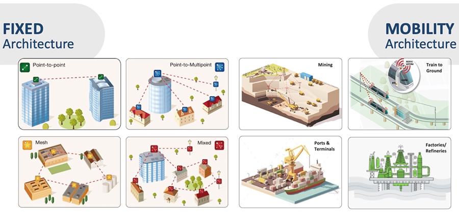
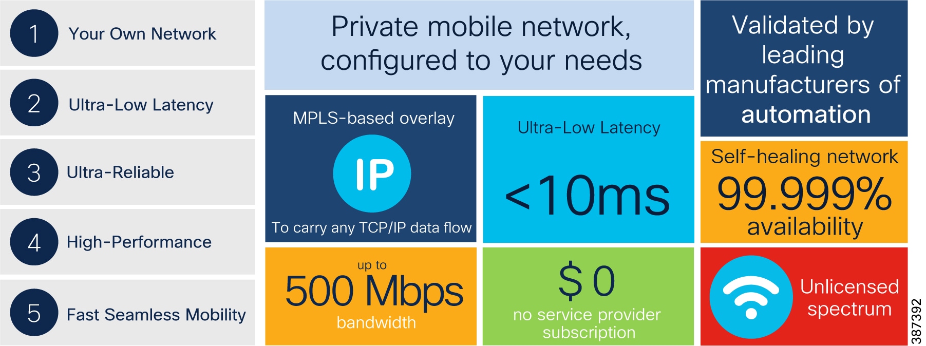
Cisco Ultra-Reliable Wireless Backhaul (CURWB) is the worldwide leader in wireless systems for security, industrial, and mission-critical applications. CURWB is a wireless technology that enables one to connect moving assets or extend the network wirelessly where running fiber isn't feasible or affordable. It delivers up to a 7.8-Gbps data rate, 99.995% availability, less than 10-ms latency, and zero packet loss with seamless handoffs. CURWB operates in the unlicensed ISM band, is easy to deploy, manage, troubleshoot, and provides full control of the network. Reliable, scalable, and suitable for the most demanding wireless applications, CURWB is a leading-edge solution for vehicle connectivity for mission-critical applications.
CURWB solutions are used by municipalities, industrial plants, schools, seaports and marinas, archaeological sites, resorts, theme parks, and racetracks.
Figure 9 CURWB Fixed and Mobility Architectures
CURWB - Technology Pillars
Three key technologies underlay the foundation for the Cisco Ultra-Reliable Wireless Backhaul (CURWB) solution:
■![]() Prodigy 2.0: MPLS-based transmission protocol built to overcome the limits of standard wireless protocols.
Prodigy 2.0: MPLS-based transmission protocol built to overcome the limits of standard wireless protocols.
■![]() Fluidity: Proprietary fast-roaming algorithm for vehicle-to-infrastructure communication with a 0 mSec roam delay and no roam loss for speeds up to 200 Mph or 360 km/hour.
Fluidity: Proprietary fast-roaming algorithm for vehicle-to-infrastructure communication with a 0 mSec roam delay and no roam loss for speeds up to 200 Mph or 360 km/hour.
■![]() TITAN: Proprietary fast-failover high-availability mechanism that provides hardware redundancy and carrier-grade availability.
TITAN: Proprietary fast-failover high-availability mechanism that provides hardware redundancy and carrier-grade availability.
Prodigy 2.0 – MPLS Overlay
Figure 10 PRODIGY MPLS Overlay Features
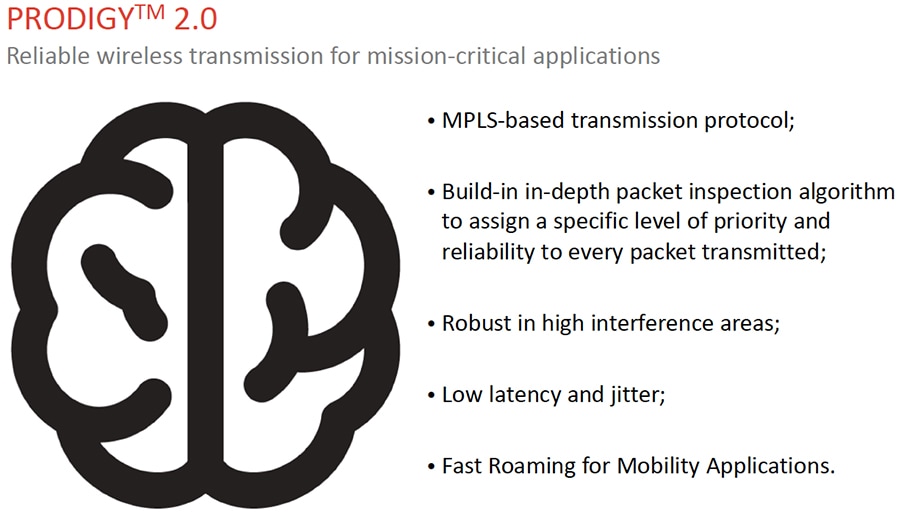
CURWB uses a proprietary wireless-based MPLS transmission protocol Prodigy to discover and create label-switched paths (LSPs) between mesh-point radios and mesh-end(s). Prodigy helps with making the wireless networks resilient and can be used for both Fixed as well as Mobility networks. MPLS provides an end-to-end packet delivery service operating between levels 2 and 3 of the OSI network stack. It relies on label identifiers, rather than the network destination address as in traditional IP routing, to determine the sequence of nodes to be traversed to reach the end of the path.
Fluidity – Seamless Roaming
Fluidity enables a vehicle that is moving between multiple infrastructure APs to maintain end-to-end connectivity with seamless handoff between APs. Vehicle radios negotiate with the infrastructure APs and form a new wireless connection to a more favorable infrastructure AP with better signal quality before breaking or losing its currently active wireless connection.
As can be seen in the figure below, because of the unique make-before-break handoff algorithm, the vehicle radios always operate on the top line (RSSI Envelope), handing over from the currently connected radio to the next available radio as soon as the difference in RSSI meets the configured threshold.
TITAN – Hardware Redundancy and High-Availability
TITAN is a proprietary fast-failover function providing high-availability and protection against hardware failures. The feature virtually guarantees uninterrupted service for mission-critical applications where safety and/or operations would otherwise be compromised by failure of a single radio or gateway device. Leveraging an MPLS-based protocol, TITAN is able to achieve device failovers within 500 mSec within both L2 and L3 networks.
Fluidity Dynamic Handoff Decision
Within standard Wi-Fi based communication, a handoff is triggered by the Wi-Fi client based on pre-configured static thresholds like RSSI and/or SNR. For example a Wi-Fi client might be configured to trigger a handoff when its RSSI value drops below -75 dBm. CURWB on the other hand uses a dynamic handoff decision algorithm.
As can be seen in the figure below, the vehicle radio always operates on the top line (RSSI Envelope), handing over from the currently connected radio to the next available radio as soon as the difference in RSSI meets the configured hysteresis threshold.
Figure 11 Fluidity Dynamic Handoff Decision
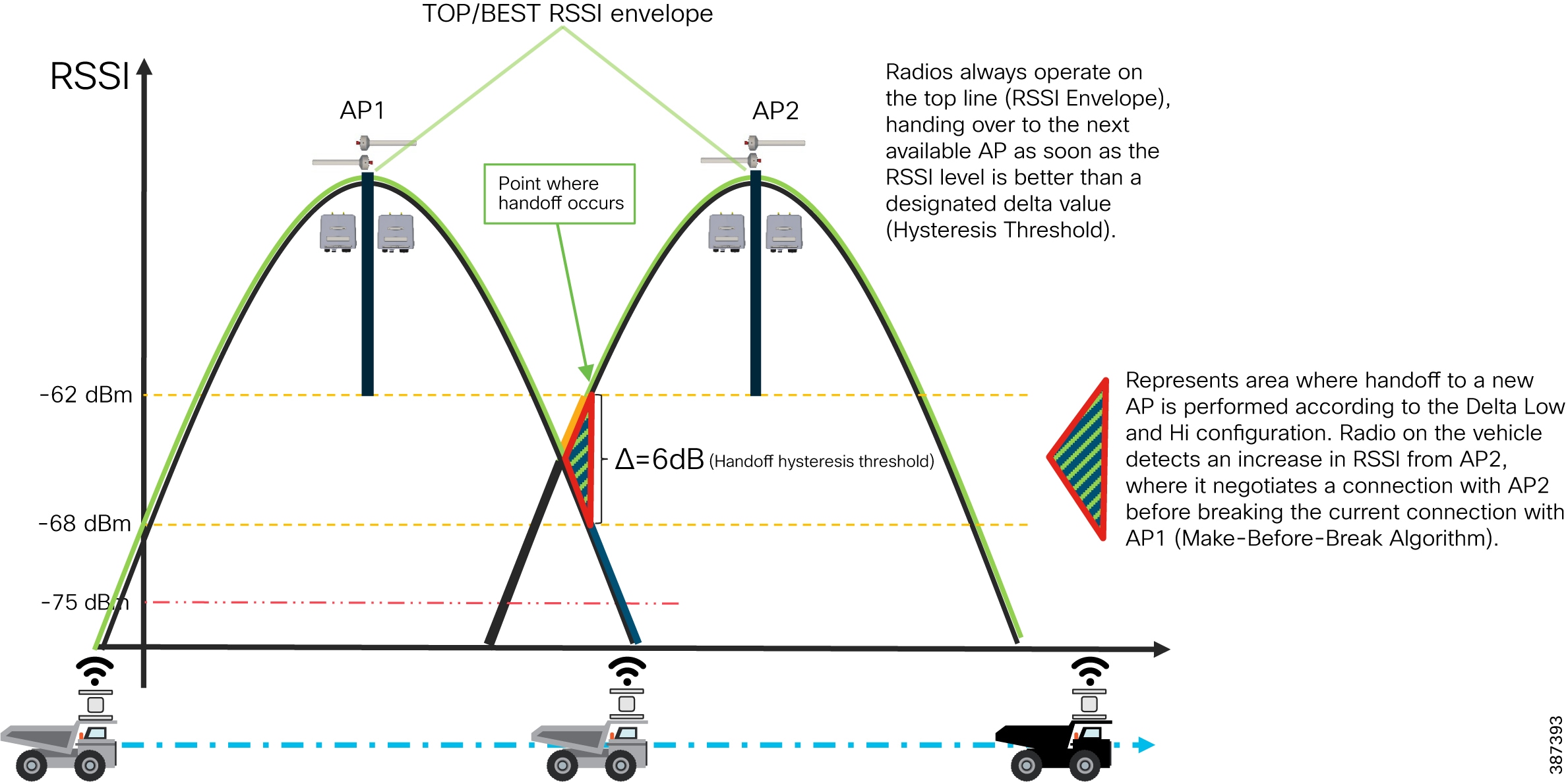
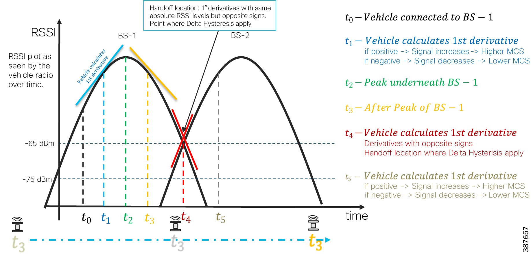
Figure 12 Fluidity Predictive Rate Selection and Handoff Location
Why CURWB?
Figure 13 Key capabilities of CURWB
Key technical requirement met by CURWB for the Factory/Warehouse AGV/AMR use-case:
■![]() Operates in globally available ISM frequency bands
Operates in globally available ISM frequency bands
■![]() Seamless roaming - 0 mSec Handoffs using proprietary Make before Break algorithm. CURWB radios offer a 0 mSec handoff that ensures the AGV rarely experiences a disconnection while roaming from one fixed radio to the next. This is achieved without any central wireless controller or complicated network configuration.
Seamless roaming - 0 mSec Handoffs using proprietary Make before Break algorithm. CURWB radios offer a 0 mSec handoff that ensures the AGV rarely experiences a disconnection while roaming from one fixed radio to the next. This is achieved without any central wireless controller or complicated network configuration.
■![]() Fast failover (TITAN) – Network convergence < 500 mSec on failure
Fast failover (TITAN) – Network convergence < 500 mSec on failure
■![]() Industrial Grade ruggedized radios that can withstand the constant vibrations that are common place in the AGV/AMR use-cases
Industrial Grade ruggedized radios that can withstand the constant vibrations that are common place in the AGV/AMR use-cases
■![]() Small form factor antenna for AGV/AMR installations
Small form factor antenna for AGV/AMR installations
■![]() A selection of Omni-Directional and Directional (Panel, Sector) antennas to provide optimal RF coverage across the Plant/Warehouse
A selection of Omni-Directional and Directional (Panel, Sector) antennas to provide optimal RF coverage across the Plant/Warehouse
CURWB Network Design for AGV/AMR
This section starts by providing an overview of the wired and wireless network components needed to deploy the solution, the architecture to support AGVs/AMRs in a Factory/Warehouse environment, followed by some design best-practices around High Availability, QoS and Security.
Wired and Wireless Network Components
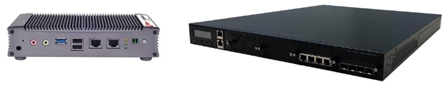
CURWB Gateway
All Fluidity / fixed infrastructure deployments need a mesh end. It functions as a gateway between wireless and wired. It is highly recommended that all systems using Fluidity use a redundant pair of mesh end gateways to terminate the MPLS tunnels, aggregate traffic and act as an interface between the wired and wireless network. Mesh End gateways can also be thought of as MPLS label edge routers (LERs) on the infrastructure network. The Mesh End gateway is responsible for encapsulating the traffic coming in from the wired network into the Fluidity overlay network using MPLS and de-encapsulating MPLS and delivering standard datagrams onto the wired network.
CURWB gateways are also used in the role of Global Gateways within a L3 Fluidity deployment where-in they form an L2TP tunnel to each of the Mesh Ends of the different subnet clusters.
It is useful to understand that the CURWB Gateways do not run any RF or handoff logic and are not to be considered as Wireless Controllers within a traditional Wi-Fi deployment.
CURWB gateways are rugged, industrial grade network appliances that make setup and management of medium and large-scale CURWB Fluidity and Fixed Infrastructure deployments fast and easy. Gateways allow the Fluidity wireless infrastructure to scale to hundreds of radio devices, without impacting the performance of the overall network.
Figure 14 FM1000 and FM10000 Mesh End Gateway Devices
CURWB FM4500 Radio Unit
Figure 15 FM4500 and FM4500 Fiber Radio Unit
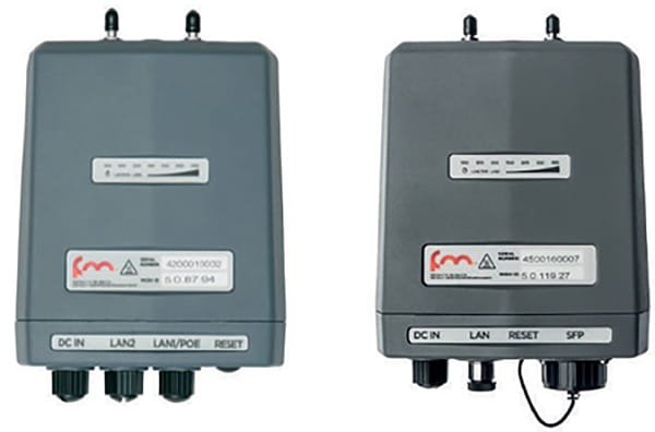
The FM4500 MOBI comes in a rugged die cast aluminum housing that has been purpose built for harsh industrial environments. It consists of industrial-grade anti-vibration M12 ports and QMA connectors, EN50155 certified. Optionally, you can also order the fiber-enabled FM4500 MOBI which supports a fiber port with an XCO connector.
The Ethernet model has 2 x 10/100/1000 M12 ports. The Fiber model has 1 x Dual LC ruggedized SFP XCO connector (transceiver not included) and 1 x 10/100/1000 M12 port. The radio can either be powered using PoE+ output from a switch or 48V DC input from an onboard power source.
Note: It is highly recommended to have a DC-to-DC converter on board vehicles to provide stable/clean power at the appropriate voltage level to the radio to avoid any damage. This is applicable when powering on the radio using the vehicle battery.
The FM4500 MOBI is the recommended radio model to be deployed on board the AGV/AMR, since it is vibration resistant. The FM4500 MOBI can also be used as the infrastructure radio.
CURWB FM3500 Endo Radio Unit

The FM3500 Endo can be exploited as a wayside radio in any vertical market that features or depends on mobility applications. As an alternative to the FM4500 radio the FM3500 can also be leveraged as a wayside radio within the Factory AGV/AMR deployment. The FM3500 Endo is a 2x2 MIMO radio with 2 x 10/100/1000 RJ45 interfaces.
RACER
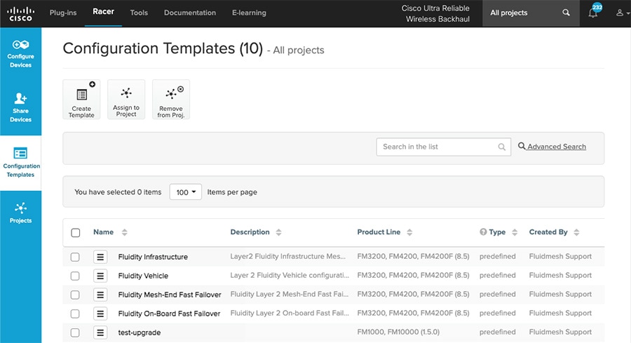
CURWB RACER is a centralized cloud-hosted server that can be used for provisioning of the entire CURWB system including configuration, firmware upgrade, and plug-in activation. It allows all the radio configuration to be done in a single pane and uploaded to the radios in real time or offline. RACER supports almost all the configuration options (basic and advanced).
RACER can be used to create configuration templates, fill in the template with the required parameter values to create radio configurations, and apply them to multiple CURWB devices of the same type. Configurations created in RACER can be applied to the radio in either online mode (if the CURWB devices have Internet access) or offline mode (if the CURWB devices have no Internet access). The advantage of using RACER is that along with the device configuration it also upgrades the firmware to the latest version available and also applies the configured plug-ins. This is the preferred method for configuring CURWB devices for any size deployment.
FM-Monitor
FM-Monitor is a network-wide, on-premises monitoring dashboard, allowing any CURWB customer to proactively maintain and monitor one or multiple wireless OT networks. FM-Monitor displays data and situational alerts from every CURWB device in a network, in real time.
FM-Monitor supports fixed and Fluidity network architectures and allows easier end-to-end troubleshooting. It can be operated as a standalone system or in parallel with a sitewide Simple Network Management Protocol (SNMP) monitoring tool. It is designed to support network installations used in smart cities, rail, mining, ports and terminals, entertainment, smart factories, and military applications.
Figure 18 FM-Monitor Topology View
■![]() On-premises monitoring tool for CURWB networks
On-premises monitoring tool for CURWB networks
■![]() Wizard setup for quick and easy installation and deployment of FM-Monitor
Wizard setup for quick and easy installation and deployment of FM-Monitor
■![]() Real-time dashboard displaying uptime, throughput, latency, jitter, and other network KPIs
Real-time dashboard displaying uptime, throughput, latency, jitter, and other network KPIs
■![]() Customizable section view to easily check groups of radios
Customizable section view to easily check groups of radios
■![]() Customizable monitoring alerts for prompt response
Customizable monitoring alerts for prompt response
■![]() Radio-by-radio data logging with a minimum sampling interval of 300 mSec
Radio-by-radio data logging with a minimum sampling interval of 300 mSec
■![]() Real-time information display for quick and accurate troubleshooting
Real-time information display for quick and accurate troubleshooting
■![]() Side-by-side comparison of radio KPIs over time and over vehicle position
Side-by-side comparison of radio KPIs over time and over vehicle position
■![]() Alerts/events can be forwarded to a Syslog server
Alerts/events can be forwarded to a Syslog server
■![]() Radio KPIs such as RSSI, LER, PER, etc. can be exported to a CSV file for graphing
Radio KPIs such as RSSI, LER, PER, etc. can be exported to a CSV file for graphing
FM-Monitor Dashboard
The dashboard shows overall network performance and offers customizable segmentation of the network into clusters. This allows for easy monitoring of network sections or parts of a fleet of vehicles, maximizing network usage and performance. Clusters can include backhaul point-to-point links, point-to-multipoint distribution networks, vehicle access networks, wayside networks, and vehicle-mounted radios. FM Monitor displays and tracks real-time Key Performance Indicators (KPIs) within each cluster, including the number of active radios, number of connected IP edge devices, end-to-end latency, jitter, upload/download throughput in real time, and system uptime.
Figure 19 FM-MONITOR Dashboard
FM-Monitor Table View
The table view allows customers to condense sections of the network into a tabular view, isolating specific radio configurations and performance statistics. During troubleshooting, this drastically reduces the time needed to understand system performance on a radio-by-radio basis.
Figure 20 FM-Monitor Table View
Figure 21 FM-Monitor Topology View
CURWB - Terminology
The following section describes some prerequisites to understand the CURWB architecture and deployment.
Mesh-ID
The Mesh-ID is a hardware identifier for the CURWB Gateways and Radios. It is pre-programmed from the factory with a hard-coded value which cannot be modified. It follows the Format of 5.x.x.x. Note that this is NOT an IP Address. The Mesh-ID is a decimal representation of the MAC address of the wireless interface. So if one were to convert the Mesh ID (from decimal to a Hex value) we will get back the MAC address of the wireless interface. That is how we guarantee the uniqueness of the Mesh-ID.
The Mesh-ID is relevant within the constructs of network design. A gateway/radio with lower Mesh-ID becomes the “primary”. Also the gateway/radio with the lowest Mesh-ID becomes the Mesh-End (if one is not explicitly configured).
The Mesh-ID of the radios is also used for license activation and receiving its configuration from RACER. RACER outputs a single file containing the licenses and configuration for a group of similar radios. The way the appropriate licenses and configuration is applied to a particular radio is based on its Mesh-ID. The Mesh-ID is tied to the Serial Number.
Passphrases
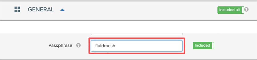
CURWB gateways/radios are configured with shared passphrases. CURWB control plane traffic is encrypted using this passphrase. The passphrase can also be used a means to segment a particular network in that radios with the same shared passphrase form a cluster and are kept separate from other CURWB MPLS networks which use a different passphrase.
Note: Data-plane / user traffic is not encrypted using the passphrase. In order to encrypt data-plan / user traffic, AES encryption must be enabled on the gateways/radios.
Note: If a shared passphrase is defined, the same passphrase must be used for all CURWB units in the same network. As a deployment best-practice configure the passphrase to be something other than the default value of “Fluidmesh”. The shared passphrase can be composed of any ASCII characters except the following: '`"\$=
CURWB Mesh End
A logical Mesh End (ME) can be redundant consisting of two physical Mesh End gateways/radios with the TITAN high-availability plug-in. The ME is typically configured within the Distribution or Core network. The purpose of the Mesh End radio is to terminate all the MPLS label-switched paths and act as a gateway between the CURWB network and the wired network. The ME holds all the Label Switch Paths (LSPs) to all the other radios in its database.
Note: Even though the CURWB solution has the capability to automatically select the gateway/radio with the lowest Mesh-ID to become the ME, as a best-practice it is highly recommended to configure the role of Mesh End and Mesh Point(s) manually within the deployment to have more deterministic convergence in case of failure within the network.
CURWB Network Design
MTU Considerations
■![]() Similar considerations as for normal MPLS
Similar considerations as for normal MPLS
■![]() Minimum required MTU on switches = 1548
Minimum required MTU on switches = 1548
■![]() Radios don’t have to be configured with MTU – this is done automatically
Radios don’t have to be configured with MTU – this is done automatically
The reason we need to increase the MTU size from the default value of 1500 to 1548 is to account for the addition of the MPLS header and avoid any fragmentation on the wired network.
Spanning Tree Protocol (STP)
STP is a Layer 2 protocol that runs on switches to prevent loops in the network when there are redundant paths in the network. Switches run the STP algorithm when they are first connected to a network or whenever there is a topology change. CURWB radios do not participate in the STP alongside the switches. The radios simply forward or block the BPDU messaged depending on how they are configured. CURWB radios have an equivalent process to STP, called AutoTap, and this helps avoid any loops within the wireless network.
BPDU Snooping can be enabled or disabled on the radio, according to the configuration the radio will act or not act on the contents of the BPDU.
BPDU forwarding, configured as ‘Pass’, forwards all the BPDUs. BPDU forwarding, configured as ‘Auto’, forwards the BPDUs in the wayside space and not forward them to the vehicle space and vice-versa. When BPDU forwarding is configured as ‘Stop’, no BPDUs are forwarded.
AutoTap
AutoTap is a network loop prevention mechanism that allows CURWB radios to detect connections and allow only a dedicated ingress/egress route to and from the Mesh End or network core.
With AutoTap, only one radio will publish MAC address information, and traffic is seen coming from only one radio that gets elected as the Primary radio of the physically connected redundant group. The radio with the lowest Mesh ID is selected as the Primary radio which advertises its MAC address. With this configuration, the radios are able to detect each other over the wired connection, and forward traffic to the connected radio utilizing this connection. Routes to the core and end devices are built automatically. The result is like having a single radio with multiple wireless interfaces.
AutoTap open on the Gateway (Core Network) represents the Label Edge Router (LER). It is the unit responsible for the MPLS encapsulation/de-encapsulation of traffic from/to the wired network. All other CURWB devices within the network (secondary gateway and wayside radios) act as MPLS Label Switch Routers (LSRs). They only forward the traffic based on the Labels. On a Vehicle with more than one radio connected to the same broadcast domain, again one of the two radios (the radio with the lower mesh ID) will have the role of a LER and the other radio (with the higher mesh ID) will have the role of LSR. The LER will have its AutoTap open and the other radio on the vehicle will have its AutoTap closed.
Network Time Protocol (NTP)
As a best practice, it is highly recommended that NTP be configured on the CURWB radios. A primary and secondary NTP server IP can be configured during RACER template configuration. When enabling NTP on the radio, it will synchronize time from the NTP server usually within an hour, however we can force it to happen sooner, the connection will be down for milli-seconds when forcing the radio to connect to the NTP server.
CURWB Fluidity Advanced - Large Network Optimization
Large network optimization (LNO) is useful in large network environments of more than 50 infrastructure radios where it helps optimize the MPLS forwarding table by only establishing LSPs toward the Mesh-End unit.
The Mesh-End is the ingress/egress point of the MPLS domain. Spanning Tree Protocol (STP) is also affected in that BPDU forwarding will be disabled.
If LNO is enabled, the Mesh points will only establish LSPs with other Mesh-End devices, and it also disables STP packet and BPDU forwarding.
If LNO is disabled, LSPs will be created between all Mesh-points, and between Mesh points and Mesh-ends. STP packets and BPDU forwarding will be set to Automatic.
Fluidity Rate Adaptation
The Fluidity rate adaptation setting controls the unit’s choice of modulation coding and speed of packet transmission. Fluidity supports two different rate adaptation modes:
■![]() Standard: This option applies a standard re-active rate selection as used by Wi-Fi technology
Standard: This option applies a standard re-active rate selection as used by Wi-Fi technology
■![]() Advanced: This option applies CURWB proprietary predictive rate selection algorithm.
Advanced: This option applies CURWB proprietary predictive rate selection algorithm.
For the AGV/AMR use-case it is recommended to leverage the Advanced rate adaptation. The CURWB predictive rate selection algorithm is pro-active. When the link error rate (LER) increases there is no packet drop as the LER is kept low by predictively adjusting the data rate. The predictive algorithm tries to keep the LER and packet loss low by selecting a more conservative data rate. As opposed to this, the standard rate selection algorithm would need higher LER and packet drops to adjust to a lower data rate. Rate selection is also important to obtain good performance and to maximize the throughput of the radio communication system.
The RSSI prediction is performed by the transmitting radio using explicit feedback received from the destination radios. This results in a good estimate of the upstream channel condition. For further accuracy the system also filters out all instantaneous variation that may have a detrimental impact on the choice of the transmission rate.
The transmission rate is then selected according to the prediction of the estimated drawing from a small set of optimal rates computed by a heuristic channel estimation algorithm. Within high-speed mobility environments, the channel state changes very quickly. Therefore, it is important that the rate sampling algorithm finds the optimal rates in the shortest time possible while keeping accuracy. Failure to meet either condition typically results in low throughput, high latency, and high packet error rate (PER).
When the rate adaptation is set to Advanced, the vehicle radio bases the selection of MCS based on the RSSI received from the wayside infrastructure radio. The RSSI scale is divided into a number of non-overlapping bins, each bin corresponding to a subset of MCS values to be sampled by the rate selection algorithm. The RSSI bin definitions and their associated MCS subsets can be determined according to several criteria, which may include, for example, the sensitivity thresholds of the underlying wireless hardware. The table below shows the default values for the RSSI bins and the corresponding MCS rate selected.
|
|
|
|
Fluidity Advanced Handoff Tuning for Vehicle Radio Units
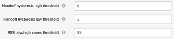
The CURWB solution provides certain advanced handoff parameters for vehicle radio units that can be tuned depending on the RF environment to achieve optimal handoffs.
The RSSI zone threshold and Handoff hysteresis threshold features provide safeguards against unwanted handoffs – in other words, against unreasonably long periods of time between received signal strength from the connected unit falling too low, and a handoff request from a relief unit.
The relationship between these three settings governs whether a handoff will take place from one unit to another, based on a difference in comparative signal amplitude values over a period of time.
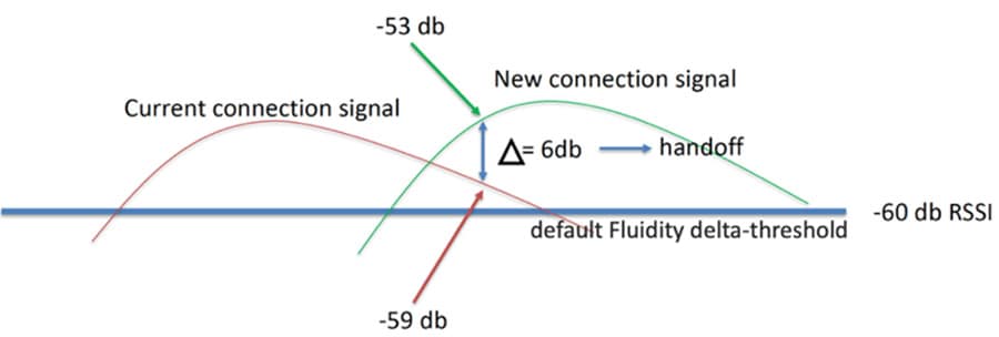
The RSSI low/high zone threshold sets the border between the low and high RSSI zones. In this case, as represented by the two graphs below, the -60 dB level marks the border between the low and high RSSI zones.
The threshold value is always expressed as SNR, with -95 dBm as the reference value, and is always expressed as a value greater than 0. The default value is 35. This equates to -60 dBm.
The default Fluidity delta-threshold is -60dBm. The default delta-high threshold is 6 dBm. What this means is that in good RF environments where the signal strength is higher than -60 dBm, the vehicle radio will only attempt a handoff to another wayside infrastructure radio if it provides a signal that is at least 6 dBm higher than what it is receiving from its currently connected wayside infrastructure radio. If the delta value is lower than 6, no handoff will occur at that time.
Figure 24 Fluidity delta-high example
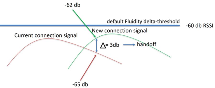
The default delta-low threshold is 3 dBm. What this means is that in poor RF environments where the signal strength is lower than -60 dBm, the vehicle radio will attempt a handoff to another wayside infrastructure radio if it provides a signal that is at least 3 dBm higher than what it is receiving from its currently connected wayside infrastructure radio. If the delta value is lower than 3, no handoff will occur at that time.
Figure 25 Fluidity delta-low example
Note: The Fluidity delta-threshold, the delta-high and delta-low values are all configurable to values different from the default using either RACER or the radio CLI if needed for your RF environment tuning.
Figure 26 RACER Fluidity Advanced Handoff parameters
CURWB Radio Behavior
Below describes the typical behavior of a CURWB radio:
■![]() Populate local VBR (Virtual Bridge Routing) table with local end points
Populate local VBR (Virtual Bridge Routing) table with local end points
■![]() Over each antenna (with configured channel/frequency): Find peer radios
Over each antenna (with configured channel/frequency): Find peer radios
–![]() Condition: Same passphrase, same cluster-id
Condition: Same passphrase, same cluster-id
■![]() Find peer radios and gateways
Find peer radios and gateways
■![]() Pseudowire-set: “Mesh-End only”: To Mesh End only
Pseudowire-set: “Mesh-End only”: To Mesh End only
■![]() Pseudowire-set: “All”: To all other radios
Pseudowire-set: “All”: To all other radios
■![]() Radio metrics determine path: Higher signal strength wins over alternative path (over full path)
Radio metrics determine path: Higher signal strength wins over alternative path (over full path)
■![]() Used for Loop Avoidance when two radios using the same passphrase are directly connected using the wired and wireless network
Used for Loop Avoidance when two radios using the same passphrase are directly connected using the wired and wireless network
■![]() Directly connected radios select a primary; radio with lower mesh-id becomes primary; only primary announces local endpoints either connected via switch or directly to a radio
Directly connected radios select a primary; radio with lower mesh-id becomes primary; only primary announces local endpoints either connected via switch or directly to a radio
■![]() The AutoTAP feature kicks in automatically and no configuration is needed
The AutoTAP feature kicks in automatically and no configuration is needed
■![]() For each LSP: announce local VBR table, Learn remote VBR table entries
For each LSP: announce local VBR table, Learn remote VBR table entries
Note: AutoTAP is independent of LSPs. It does not influence LSPs or block switch ports (like STP does). It does however block the Ethernet interface of the CURWB radio if a loop is detected. From the directly connected switche’s perspective the port will still show as up and running, however in actuality the port will be blocked by the CURWB radio’s AutoTap logic.
QoS Implementation on CURWB Radios
The CURWB Prodigy 2.0 forwarding engine embeds a DiffServ-inspired framework to provide end-to-end QoS treatment to user traffic. The system support 8 priority levels, numbered from 0 to 7 with the former being the lowest and the latter being the highest, respectively.
When a client device IP packet first enters the mesh at an ingress CURWB router, the TOS/DSCP field of the IP header is inspected in order to assign a priority class to the packet. The class number is taken from the 3 most significant bits (b7-b5) of the TOS/DSCP field.
The default system setting is to preserve the original priority marking unchanged. The priority tag is then preserved through the whole end-to-end path to the egress router, where the packet leaves the CURWB network to be delivered to the destination client device. Priority scheduling is applied at the different transmission interfaces for each hop along the path.
For packets being transmitted over the wireless, the eight priority levels are further mapped into four access categories after scheduling (see table below). Each access category corresponds to a specific set of MAC transmission parameters which provide different levels of robustness and performance.
An important thing to note here is that for traffic marked with CoS-6 and 7, CURWB disables packet aggregation which can otherwise delay the packet transmission over the air and add to end to end latency which is not desirable for real-time AGV control traffic.
CURWB QoS - MPLS Experimental Bits (EXP)

■![]() The MPLS experimental 3 bits (EXP) are used to provide QoS capabilities in MPLS environments
The MPLS experimental 3 bits (EXP) are used to provide QoS capabilities in MPLS environments
■![]() The 3 EXP bits allows 8 different classifications of traffic, based on information found in the Layer 3 DSCP, or the Layer 2 CoS
The 3 EXP bits allows 8 different classifications of traffic, based on information found in the Layer 3 DSCP, or the Layer 2 CoS
■![]() During the MPLS encapsulation process, the QoS markings are copied into the EXP field in the MPLS header from the IP header, or from the ethernet header, which is the PCP field in the VLAN tag
During the MPLS encapsulation process, the QoS markings are copied into the EXP field in the MPLS header from the IP header, or from the ethernet header, which is the PCP field in the VLAN tag
■![]() For QoS purposes, CURWB units do not examine the IP header or ethernet header during the forwarding process. They examine the EXP bits, giving prioritization of one traffic type over another based on the assigned markings.
For QoS purposes, CURWB units do not examine the IP header or ethernet header during the forwarding process. They examine the EXP bits, giving prioritization of one traffic type over another based on the assigned markings.
■![]() The MPLS experimental 3 bits is highlighted in yellow in the MPLS Header shown in the figure above
The MPLS experimental 3 bits is highlighted in yellow in the MPLS Header shown in the figure above
Security - AES Encryption
All client traffic within the MPLS tunnel is kept private (not encrypted) using the system passphrase, however for additional security the CURWB solution also supports enabling AES encryption to encrypt all traffic over the wireless medium. It is highly recommended to enable AES encryption within an AGV/AMR deployment.
Note: To enable AES encryption feature, an AES plug-in needs to be installed on the radio. When configuring AES encryption, it is mandatory to enable AES encryption on all the radios within the system. Enabling AES only for a sub-section of the system is not supported and will cause a breakage. The FM1000/10000 gateways already don’t need an AES plug-in.
CURWB L2 Fluidity
L2 Fluidity provides simple and seamless mobility within a single broadcast domain. All the devices (PLCs, I/O, CURWB radios, CURWB gateways) use the same subnet and default gateway. Full VLAN support is available. The disadvantage of L2 Fluidity is that it is only constrained to a single broadcast domain and provides limited scale with a maximum of ~ 200 devices.
In case of a L2 Fluidity deployment no router is needed on-board the vehicles since the entire deployment is a flat L2 network. From each vehicle radio there is an MPLS Label Switched Path (LSP) to each Mesh End. In case or redundant Mesh Ends and redundant radios on the vehicle, there will be a total of 4 LSPs per vehicle and only one of the LSPs will be active. Any IP traffic received from the on-board devices (PLC, I/O, etc.) received by the onboard radio(s) is encapsulated into MPLS packet and sent across an LSP towards the CURWB Mesh End. For small deployments the CURWB mesh can use a CURWB radio may be able to be used as a Mesh End. For larger deployments a CURWB gateway like the FM1000 should can be used. The Mesh End receives the MPLS packet, de-encapsulates it and delivers the original IP packet to the distribution/core network.
Figure 28 L2 Fluidity Packet Flow
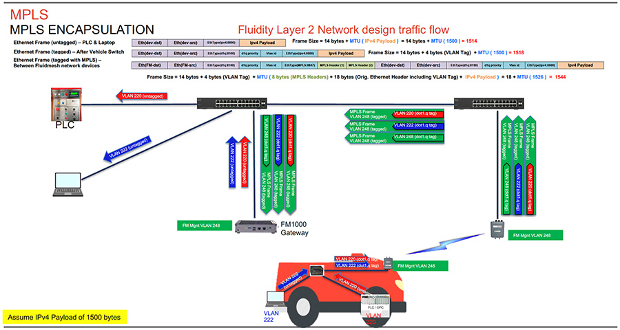
The figure above depicts the L2 Fluidity packet flow from the vehicle to the control room. The laptop on the vehicle is configured to be in Access VLAN 222 and the PLC is configured to be in Access VLAN 220. The packets from the laptop and PLC on board the vehicle are untagged when they enter the on board switch. Assuming an IPv4 payload of 1500 bytes, the untagged ethernet frame size is 1514 bytes. The switch on board the vehicle adds the appropriate IEEE 802.1q VLAN tag to each of the packets. After the IEEE 802.1q VLAN tag of 4-bytes is added, the frame size is now 1518 bytes. The IEEE 802.1q tagged packets are then forwarded to the CURWB radio on board the vehicle.
The CURWB radio on board the vehicle then takes those packets and inserts an MPLS label, tags them with the CURWB Mgmt VLAN IEEE 802.1q tag (VLAN-248) and forwards them to the wayside infrastructure CURWB radio to where the vehicle radio is currently connected. Along with the MPLS header of 8-bytes an additional IEEE 802.1q VLAN tag of 4 bytes and an ethernet frame of 14-bytes the frame size now becomes 1544 bytes. The MPLS encapsulated frames with an IEEE 802.1q tag of VLAN-248 are forwarded to the CURWB FM1000 gateway.
The CURWB FM1000 gateway de-encapsulates the MPLS header and forwards the original IEEE 802.1q tagged frames onward to the control room switch. The control room switch removes the 802.1q header and forwards the frames towards their intended destination.
CURWB L3 Fluidity
L3 Fluidity provides seamless mobility with higher scalability. In case of a L3 Fluidity deployment each wayside section has its own subnet and each vehicle has its own subnet. L2TP tunnels link each of the wayside sections to the Global Gateway(s). A L3 Fluidity deployment is slightly more complex as compared to a L2 Fluidity deployment. As in L2 Fluidity, the MPLS LSP for each of the vehicles terminates at the Mesh End. The packet is then forwarded into an L2TP tunnel and forwarded towards the Global Gateway which de-encapsulates the L2TP header and forwards the original IP packet to the core network. Any traffic entering the CURWB network from the core network is encapsulated within the L2TP tunnel and forwarded to the appropriate Mesh End.
CURWB Single Frequency Design
In case of a CURWB single-frequency design, all the CURWB radios infrastructure and vehicles operate on the same frequency which is statically configured. An advantage of this design is that the vehicle radios don’t need to perform any off-channel scanning and hence enable seamless 0 mSec handoff from one infrastructure AP to another. Another big advantage of this design is that the deployment can use the cleanest channel available (determined as an outcome of the site spectrum analysis) and interference on other neighboring channel does not affect the system hence providing reliable wireless connectivity. Since the throughput and density requirements for a typical AGV/AMR system is not large a single-frequency design should be able sufficient to satisfy all requirements.
CURWB Multi Frequency Design
For large AGV/AMR deployments with a high density of AGV/AMR per infrastructure AP a single frequency design might most likely result in high channel utilization leading to higher contention on the wireless medium resulting in higher link and packet error rate. This is not desirable for a real-time control application such as AGV/AMR.
An alternative to the single frequency design described above CURWB also supports a Multi-Freq design to address the needs of larger and denser vehicle deployments. In a multi-frequency design two or more frequencies can be selected to provide coverage across the plant floor. For large and dense AGV/AMR deployments this design will provide superior performance by helping reduce the channel utilization (resulting in lower contention, retries and packet loss) and thus enabling a more stable and reliable wireless deployment.
CURWB supports two designs for implementing a multi-frequency architecture – Static and Dynamic.
Static Multi-Frequency Design
In order to implement a Static Multi-Frequency design we need to increase the number of wayside infrastructure APs. The APs should be deployed in such a manner that coverage for all frequencies should be available throughout the plant floor. In this design a subset of vehicles will be operating on Freq-A and a subset of vehicles will be operating on Freq-B as an example. The design needs to ensure that there is appropriate coverage for both Frequencies A and B across the plant floor. For the static multi-frequency design there is no change needed on the vehicle side, with each of the vehicles only needing a single CURWB radio like in the single frequency design.
Dynamic Multi-Frequency Design
The dynamic multi-frequency design is pretty similar to traditional Wi-Fi design where-in adjacent infrastructure APs is on a different frequency (Freq-A, Freq-B, Freq-C, Freq-A, Freq-B, Freq-C and so on).
In order to implement a Dynamic Multi-Frequency design a change needs to be made on the vehicle end. Due to the nature of the design, the vehicle radio now needs to go off-channel to look for an AP providing a better signal while roaming across the plant floor. This functionality is termed as off-channel scanning. In order to perform off-channel scanning, the vehicle AP servicing client traffic on the current channel briefly needs to stop servicing client traffic and jump off-channel to scan for a better infrastructure AP to associate with. This results in a brief interruption to the client traffic which is not acceptable for real-time applications such as AGV/AMR control applications. To overcome this challenge the CURWB dynamic multi-frequency design supports installing two APs on each of the vehicles with one AP actively servicing client traffic while the second AP can perform the dedicated off-channel scanning functionality. This dual-AP vehicle design provides the same 0 mSec seamless roaming available in the single-frequency design.
CURWB System Design Considerations
■![]() AGV/AMR density within a particular region of the Warehouse or Factory Plant Floor. Total number of AGV/AMR that need to be supported at a given site.
AGV/AMR density within a particular region of the Warehouse or Factory Plant Floor. Total number of AGV/AMR that need to be supported at a given site.
■![]() Support for any other type of traffic over the wireless network other than Industrial protocol (e.g., unicast, multicast, broadcast, GPS data, etc.)
Support for any other type of traffic over the wireless network other than Industrial protocol (e.g., unicast, multicast, broadcast, GPS data, etc.)
■![]() Provide good radio coverage across the intended AGV/AMR path.
Provide good radio coverage across the intended AGV/AMR path.
■![]() High vehicle densities result in more interference and contention in the affected areas. The OMNI-3, an antenna designed for optimum performance at low signal strengths, is most suitable for this purpose.
High vehicle densities result in more interference and contention in the affected areas. The OMNI-3, an antenna designed for optimum performance at low signal strengths, is most suitable for this purpose.
■![]() Factory/Warehouse environments will most likely have metallic objects which could cause signal blockages and unwanted signal reflections.
Factory/Warehouse environments will most likely have metallic objects which could cause signal blockages and unwanted signal reflections.
■![]() An on-site spectrum analysis must always be performed to establish which radio channels can be used for the deployment and to ensure that the proposed spectrum is clean.
An on-site spectrum analysis must always be performed to establish which radio channels can be used for the deployment and to ensure that the proposed spectrum is clean.
■![]() The recommended radio for deployment on AGV/AMR is the FM4500 Mobi since it is vibration-resistant and provides M12 X-coded LAN connectors.
The recommended radio for deployment on AGV/AMR is the FM4500 Mobi since it is vibration-resistant and provides M12 X-coded LAN connectors.
■![]() The FM4500 Mobi can be powered using either 802.11at PoE+, or through the DC IN port, providing a flexible choice of how to power up the radio.
The FM4500 Mobi can be powered using either 802.11at PoE+, or through the DC IN port, providing a flexible choice of how to power up the radio.
■![]() High vehicle densities result in more interference and contention in the affected areas. The OMNI-3, an antenna designed for optimum performance at low signal strengths, is most suitable for this purpose.
High vehicle densities result in more interference and contention in the affected areas. The OMNI-3, an antenna designed for optimum performance at low signal strengths, is most suitable for this purpose.
–![]() The OMNI-3 is the antenna of choice for both infrastructure radios and AGV/AMR radios.
The OMNI-3 is the antenna of choice for both infrastructure radios and AGV/AMR radios.
–![]() The OMNI-3 antenna has a low gain, helping minimize interference within the indoor areas where the AGV/AMR move and it has a radiation pattern that helps eliminate ‘dead spots’ if a vehicle passed underneath it.
The OMNI-3 antenna has a low gain, helping minimize interference within the indoor areas where the AGV/AMR move and it has a radiation pattern that helps eliminate ‘dead spots’ if a vehicle passed underneath it.
–![]() The OMNI-3 antenna also has a small form factor which makes it ideal for installation on vehicles where space is limited.
The OMNI-3 antenna also has a small form factor which makes it ideal for installation on vehicles where space is limited.
■![]() Adjustments to the system design are needed whenever an RF simulation or an active RF survey does not show an expected level or RF coverage.
Adjustments to the system design are needed whenever an RF simulation or an active RF survey does not show an expected level or RF coverage.
■![]() Always locate vehicle antennas in areas where there is as little metal as possible. Metal reflects and degrades the RF signals.
Always locate vehicle antennas in areas where there is as little metal as possible. Metal reflects and degrades the RF signals.
■![]() Radios and antennas must be quickly accessible for easy maintenance.
Radios and antennas must be quickly accessible for easy maintenance.
■![]() If the chosen hardware placement does not work well during initial testing, try moving the antennas to a different location.
If the chosen hardware placement does not work well during initial testing, try moving the antennas to a different location.
■![]() Customer performance requirements (for e.g., minimum and maximum bandwidth, PLC safety cycle, VLAN, QoS, Industrial protocol in use – CIP, CIP Safety, PROFINET, PROFIsafe).
Customer performance requirements (for e.g., minimum and maximum bandwidth, PLC safety cycle, VLAN, QoS, Industrial protocol in use – CIP, CIP Safety, PROFINET, PROFIsafe).
■![]() Collect key data as part of a site survey:
Collect key data as part of a site survey:
–![]() Have a detailed floor plan or blueprint of the Warehouse or Factory Plant Floor
Have a detailed floor plan or blueprint of the Warehouse or Factory Plant Floor
–![]() Location of existing backbone network infrastructure, such as fiber drops or switches
Location of existing backbone network infrastructure, such as fiber drops or switches
–![]() Metallic Object obstructing or reflecting RF signal (Robots, Machinery, Shelves, Roof, etc.)
Metallic Object obstructing or reflecting RF signal (Robots, Machinery, Shelves, Roof, etc.)
–![]() Any other obstructions (walls, catenary structures, buildings, etc.)
Any other obstructions (walls, catenary structures, buildings, etc.)
–![]() Number and type of vehicles. Speed of vehicles.
Number and type of vehicles. Speed of vehicles.
–![]() Intra-Cell and Inter-Cell roam requirement?
Intra-Cell and Inter-Cell roam requirement?
–![]() Location and availability of power to install infrastructure APs.
Location and availability of power to install infrastructure APs.
–![]() Location and availability of power to install vehicle radiosAPs(s).
Location and availability of power to install vehicle radiosAPs(s).
–![]() Perform a spectrum scan to determine what radio channel(s) can be used for the deployment.
Perform a spectrum scan to determine what radio channel(s) can be used for the deployment.
■![]() Perform an active site survey to determine if the amount of deployed wayside CURWB infrastructure RF coverage meets both the customer and application KPI requirements.
Perform an active site survey to determine if the amount of deployed wayside CURWB infrastructure RF coverage meets both the customer and application KPI requirements.
CIP Safety over Wireless - Design Considerations
■![]() What is the CIP Safety Requested Packet Interval (RPI) requirement for the automation system?
What is the CIP Safety Requested Packet Interval (RPI) requirement for the automation system?
■![]() CIP Safety: What is the timeout interval set to? (RPI x timeout = The safety requirement of the system)
CIP Safety: What is the timeout interval set to? (RPI x timeout = The safety requirement of the system)
■![]() What is the size of the network, and how many access points are required?
What is the size of the network, and how many access points are required?
■![]() AGV/AMR density. Total number of AGVs that need to be supported?
AGV/AMR density. Total number of AGVs that need to be supported?
■![]() What policies are in place so that RF interference is not introduced in the future as more wireless networks are added.
What policies are in place so that RF interference is not introduced in the future as more wireless networks are added.
■![]() Know which setup decisions will most likely impact wireless network performance. That means looking carefully at the PLC communications, the requested packet interval (RPI), and the time out multiplier - if these values are set too short, communication faults can be expected. Getting the RPI right is important - too fast and it’ll create unnecessary traffic on the network, overloading the network will result in triggering communication faults.
Know which setup decisions will most likely impact wireless network performance. That means looking carefully at the PLC communications, the requested packet interval (RPI), and the time out multiplier - if these values are set too short, communication faults can be expected. Getting the RPI right is important - too fast and it’ll create unnecessary traffic on the network, overloading the network will result in triggering communication faults.
■![]() Determine the total network load or how many packets per second will be produced, because if the network is overwhelmed, communication faults will be triggered and the AGV(s) will stop. It’s best to have a dedicated channel that’s not used in any other wireless systems in the facility. That allows radios to talk without interference from other wireless networks.
Determine the total network load or how many packets per second will be produced, because if the network is overwhelmed, communication faults will be triggered and the AGV(s) will stop. It’s best to have a dedicated channel that’s not used in any other wireless systems in the facility. That allows radios to talk without interference from other wireless networks.
■![]() Need to determine Channel Width depending on AGV density per Infra AP on the Plant Floor/Warehouse
Need to determine Channel Width depending on AGV density per Infra AP on the Plant Floor/Warehouse
■![]() Need to tune the CIP Safety Request Packet Interval (RPI) rate between Wired Safety PLC and Wireless Safety I/O to avoid connection timeouts
Need to tune the CIP Safety Request Packet Interval (RPI) rate between Wired Safety PLC and Wireless Safety I/O to avoid connection timeouts
■![]() Need to tune the Timeout Multiplier between Wired Safety PLC and Wireless Safety I/O to avoid connection timeouts in case of consecutive packet loss
Need to tune the Timeout Multiplier between Wired Safety PLC and Wireless Safety I/O to avoid connection timeouts in case of consecutive packet loss
■![]() Total (Upstream + Downstream) traffic per AGV will need to be factored into the above planning
Total (Upstream + Downstream) traffic per AGV will need to be factored into the above planning
■![]() Any other non-AGV traffic over the CURWB Wireless network will also need to be factored into the calculations. It is highly recommended to not have any additional traffic running over the CURWB network designed to support AGV/AMR application.
Any other non-AGV traffic over the CURWB Wireless network will also need to be factored into the calculations. It is highly recommended to not have any additional traffic running over the CURWB network designed to support AGV/AMR application.
PROFINET over Wireless – Design Considerations
PROFINET (PN) communication can also be realized over a standard IEEE 802.11 wireless connection. While some PROFINET IO (PNIO) devices have built-in wireless client capabilities, the majority of PNIOs only support Ethernet interfaces. In those cases, system integrators will need to connect the PNIO to a wireless client device that acts as a wireless adapter to communicate with the PN controller.
In order to design and deploy the right wireless solutions to support PROFINET communication, several key aspects of wireless networking need to be taken into consideration. These include L2 transparency limitations, higher latency, and radio frequency (RF) management to configure the wireless environment for optimal performance.
PROFINET real-time (RT) communication requires the underlying network infrastructure to be Layer 2 transparent in order to forward data frames correctly. The deployed wireless solution must support L2 forwarding.
Some other variables to consider:
■![]() The number of PNIO devices to integrate
The number of PNIO devices to integrate
■![]() The scale of the wireless network (the number of wireless devices to deploy)
The scale of the wireless network (the number of wireless devices to deploy)
L2 Fluidity Architecture for Factory AGV/AMR Using CIP Safety
Figure 29 CURWB L2 Fluidity Architecture for Factory AGV/AMR
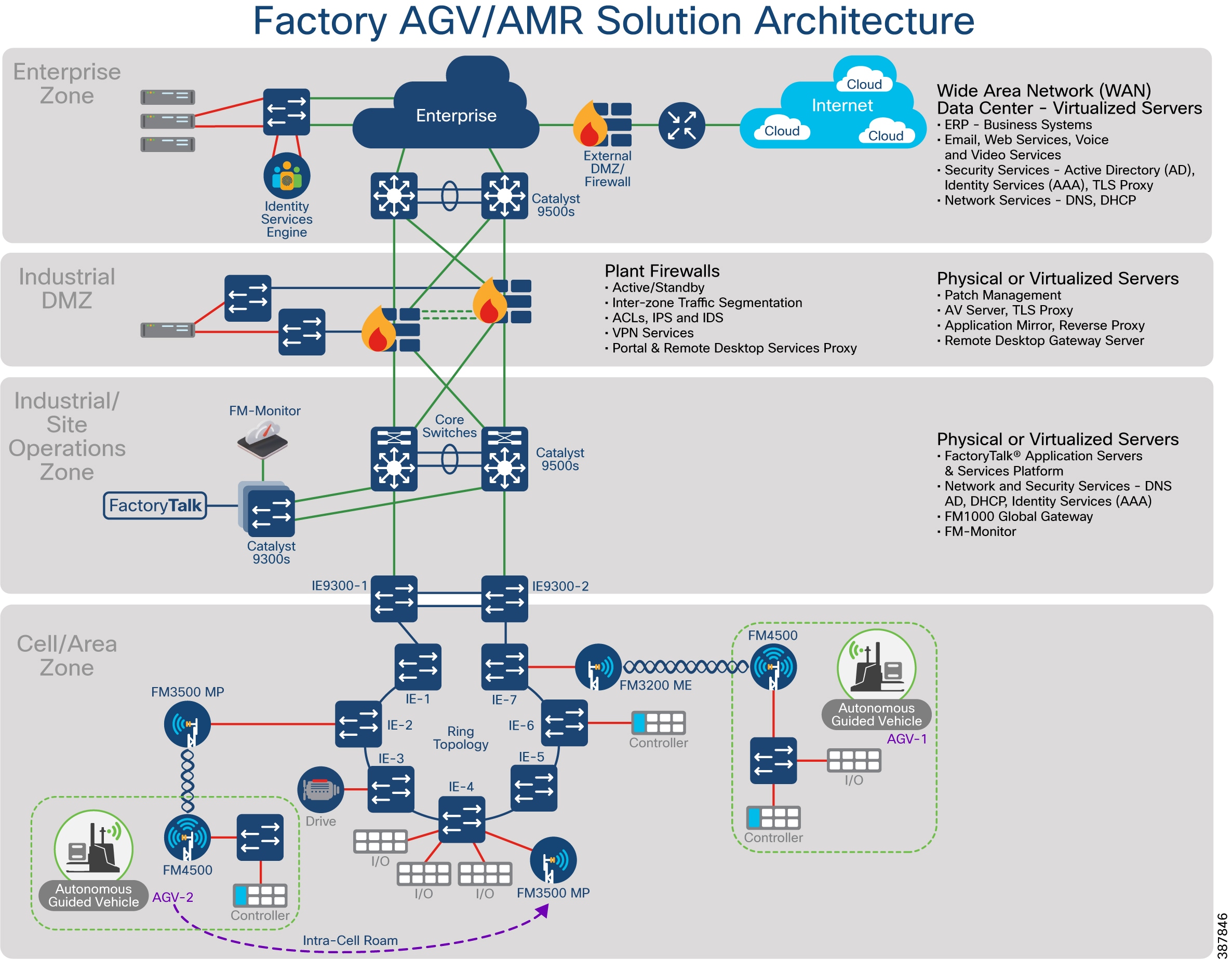
The Purdue Model for Control Hierarchy (reference ISBN 1-55617-265-6) is a common and well-understood model in the manufacturing industry that segments devices and equipment into hierarchical functions. It has been incorporated into many other models and standards in the industry. Based on this segmentation of the plant technology, the International Society of Automation ISA-99 2-2 Committee for Manufacturing and Control Systems Security has identified the levels and logical framework. Each zone and the related levels are described in detail below.
Cell/Area Zone
The Cell Area zone is a functional zone where the industrial automation devices interact with each other. It can be visualized as a kitchen area where the chefs prepare the food. The network is a critical factor because all the automation devices must communicate to ensure that goods are produced. A plant factory may have one or multiple cell zones. Each cell can have the same or different topologies. The diagram represents the one used in this design for validating the PROFINET 2.0 solution.
Manufacturing Zone
The Manufacturing zone comprises the Cell/Area zones (Levels 0 to 2) and site-level (Level 3) activities. The Manufacturing zone is important because all the IACS applications, devices, and controllers critical to monitoring and controlling the plant floor IACS operations are in this zone. To preserve smooth plant operations and functioning of the IACS applications and IACS network, this zone requires clear logical segmentation and protection from Levels 4 and 5 of the plant/enterprise operations.
CURWB L2 Fluidity Architecture
For deployments that do not need support for inter-cell AGV roaming the recommended deployment topology is L2 Fluidity. The figure above depicts a typical L2 Fluidity mobility architecture for a single cell factory environment. A pre-requisite for L2 Fluidity is that all the CURWB devices (mesh-end gateways, access radios, and mobile radios) need to be within the same VLAN/IP subnet/L2 broadcast domain and configured with the same passphrase.
Note: L2 Fluidity can also be implemented without the use of the ring topology as depicted above. In that case the CURWB access radios can be connected to the access layer switches within the deployment.
The deployment consists of a redundant pair of mesh-end gateways. The mesh-ends can either be CURWB radios for smaller deployments of FM1000 gateways for larger deployments. The role of the mesh-ends is to terminate the MPLS tunnels from each of the vehicles and access radios and act as a demarcation point between the wired and the wireless domains. The mesh-ends are responsible for de-encapsulating the MPLS header and then forwarding the traffic to the distribution/core switch. For the traffic originating from the wired network and going towards the mobility domain, the mesh-ends act as the “default gateway” and are also responsible for the MPLS encapsulation and forwarding the traffic to the appropriate vehicle radio.
The access radios are configured as mesh points in the L2 Fluidity mode with the same passphrase that is configured on the mesh-ends. The role of the access radios is to provide RF coverage for the mobility domain. The access radios are distributed across the area where wireless coverage is required while the AGV/AMR roam.
The CURWB radio on the vehicles is configured in “Vehicle” mode.
The CURWB network architecture is based on Prodigy 2.0, MPLS-based technology, which is used to deliver IP-encapsulated data. MPLS provides an end-to-end packet delivery service operating between levels 2 and 3 of the OSI network stack. It relies on label identifiers, rather than the network destination address as in traditional IP routing, to determine the sequence of nodes to be traversed to reach the end of the path.
An MPLS-enabled device is also called a Label Switched Router (LSR). A sequence of LSR nodes configured to deliver packets from the ingress to the egress using label switching is denoted as a Label Switched Path (LSP), or “tunnel”. LSRs situated on the border of an MPLS-enabled network and / or other traditional IP-based devices are also called a Label Edge Router (LER). The ingress node of the path classifies incoming packet according to a set of Forwarding Equivalence Classes (FEC); when a packet matches a class, it is marked with the label associated with the particular class and then forwarded to the next node of the sequence, according to the information configured into the Forwarding Information Base (FIB) table of the node. Subsequently, each intermediate node manipulates the MPLS label(s) stored into the packet and then it forwards the data to the next node. The egress node finally removes the label and handles the packet using normal IP routing functions.
The FIBs on the different nodes of the network are managed by means of a Label Distribution Protocol (LDP) that is the primary component of the so-called network control plane. Fluidity relies on a custom label distribution protocol that provides automated installation of LSPs among the different nodes of the network; this ensures that each node can be reached from any other node.
In traditional MPLS networks, whenever the network topology changes for any reason, the FIBs of the nodes involved must be reconfigured to adapt to the new paths. This is usually performed using the standard label distribution protocol signaling available.
In a mobility network scenario, the handoff process can be assimilated to a network topology change, where a link is broken and a new one is created like in Wi-Fi. The standard mechanisms to detect the change and reconfigure the nodes are, however, too slow and data-intensive to provide adequate performance in a real-time constrained scenario such as high-speed mobility. In particular, the whole reconfiguration latency and the number of messages exchanged should be minimized to reduce the chances that some data packets are lost in the process.
To mitigate the mentioned issues, Fluidity implements a fast handoff solution that is able to provide very fast path reconfiguration with latency in the order of one millisecond. The considered mechanism is proposed as an extension to the existing control plane of the network and it is based on a specific manipulation technique concerning the MPLS FIB tables of the nodes.
The scheme proposed allows mobile nodes, and client devices attached to them, to maintain their IP address throughout the mobility process. Besides, all nodes are part of a single layer-2 mesh network. The layer-3 handoff process is seamless in the sense that, thanks to a make-before-break strategy, the availability of at least one valid LSP is ensured during the handoff transitory as the network is reconfigured.
LSPs connecting to the static backbone are installed and updated whenever the vehicle performs the handoff procedure using dedicated signaling. LSPs are always present as long as a mobile radio is communicating with a fixed infrastructure radio. Labels change as it roams, but the LSPs are always present.
L3 Fluidity Architecture for Factory AGV/AMR Using CIP Safety
Figure 30 CURWB L3 Fluidity Architecture for Factory AGV/AMR
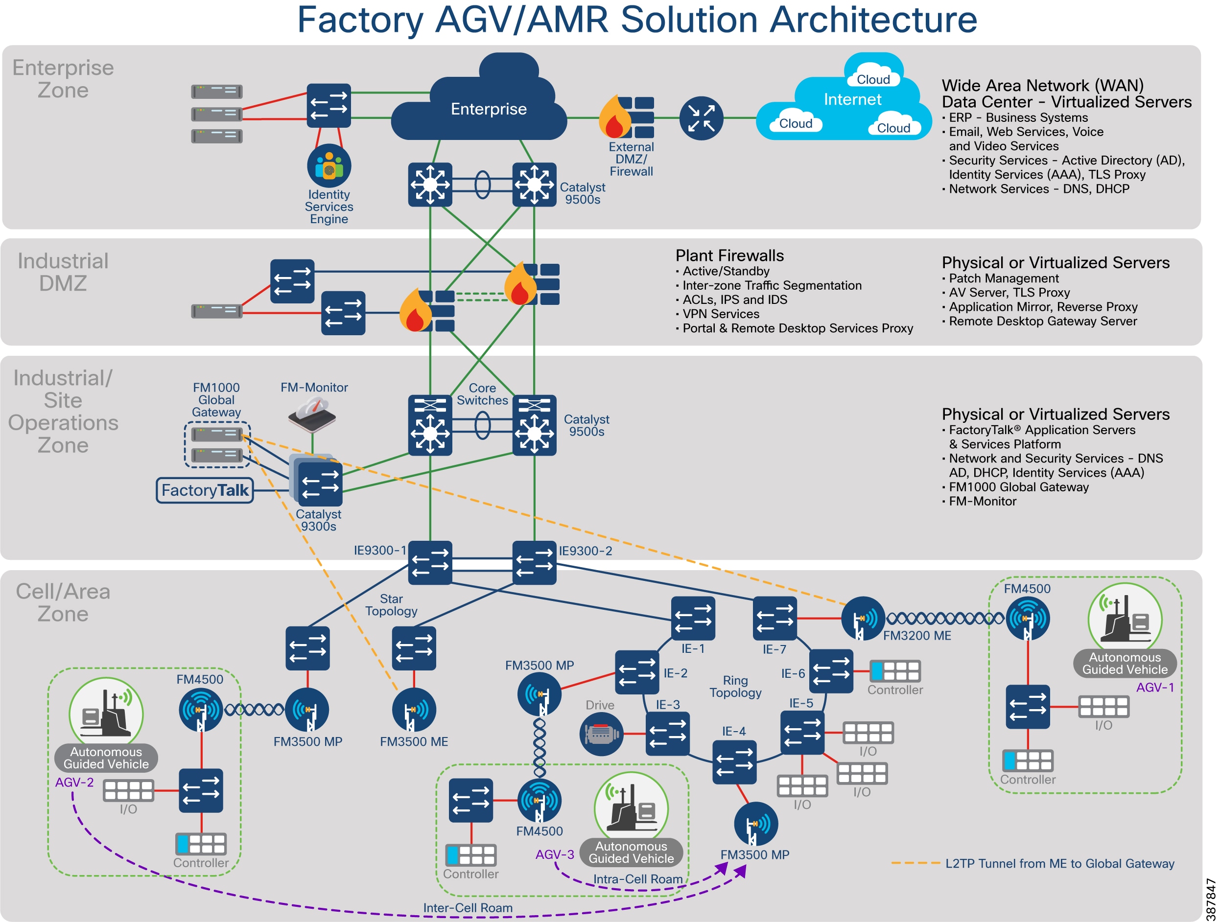
Within a Fluidity L3 design, the CURWB devices belong to different L2 broadcast domains. These domains consist of multiple subnets and are organized as separate L3 routing domains. This design needs to be implemented when the AGV/AMR needs to cross subnet boundaries from one cell/area zone to another cell/area zone, basically where there is a need to support AGV/AMR inter-cell roaming.
In this design a pair of FM1000 gateways need to be installed in the distribution or core layer to act as Global gateways. Each cell/area zone needs to have a pair of FM1000 gateways or CURWB radios configured as Mesh Ends. The traffic between the Mesh Ends in each cell and the Global Gateway is encapsulated within an L2TP tunnel. The CURWB radios are configured to belong to the subnet where they belong.
L3 Fluidity enables scalability across multiple Cell Area zones each mapped to their own subnet. Fluidity L3 sits on top of the existing networks and ‘flattens’ subnets via L2TP encapsulation between the Global Gateways and the Mesh End(s) within each Cell Area zone, allowing seamless routing and end-to-end connectivity for an AGV/AMR moving between different cell area zones and the core network.
Communication between the wayside infrastructure subnets and the Global Gateway network is provided in the routed IP network. Communication between the Global Gateway network and vehicle networks goes through the MPLS overlay and L2TP tunnels. Each radio network on the wayside corresponding to an individual Cell Area zone needs at least one Mesh End. Dual Mesh Ends can be deployed for redundancy if needed. Each of these Cell Area zones belong to different broadcast domains.
CURWB radio on-board the vehicle should be configured with a static route of each local subnet on the vehicle. This allows the vehicle radio to advertise these addresses back to the network core (Global Gateways) for network convergence. The IP address of the on-board router should be used to configure the default gateway for the vehicle CURWB radio.
Each Global Gateway should be configured to connect to the L2TP WAN address of each Mesh End. L2TP encapsulates the original IP/MPLS payload.
Both Global Gateways should be configured with the FM-TITAN plug-in enabled, enabling ta Virtual IP to be configured. This enables the network to stay converged in the event of a hardware failure on the primary helping the secondary global gateway to seamlessly take over. Additionally, the L2TP address of each Mesh End should be entered in list format on each Global Gateway to build the L2TP tunnel from the Global Gateway to each Mesh End.
The Mesh End within each Cell/Area zone can also be deployed in a pair to provide high-availability if desired. In that case both the Mesh Ends will need to be configured with the FM-TITAN plug-in enabled. The L2TP address of each Global Gateway should be entered in list format on each Mesh End to form the L2TP tunnel to the Global Gateway.
Note: L3 Fluidity deployment will not work for PROFINET requires L2 adjacency. PROFINET deployments must always use leverage the L2 Fluidity architecture design described above.
High Availability (HA)
TITAN Fast Convergence and High-Availability Plug-in
TITAN is the CURWB proprietary fast-failover function, allowing data exchange to resume almost instantaneously in case of a transceiver, switch-port and/or CURWB device failure. This unique feature can virtually guarantee uninterrupted service in mission-critical applications where safety and/or operations would otherwise be compromised by failure of one or more non-redundant radio transceiver units.
Leveraging CURWB MPLS-based protocol, TITAN is able to achieve device failovers within 500 mSec on both Layer 2 and Layer 3 networks.
Once enabled, TITAN is completely autonomous and ensures stable and reliable connectivity without the need for human supervision. If a primary device fails, the designated secondary device automatically takes over the exchange of data. If the failed primary device comes back online, the secondary device automatically reverts back to its standby role.
For faster convergence and High Availability using hardware redundancy, it is highly recommended to install theTITAN plug-in on all the gateways and radios in the deployment.
■![]() Vehicles with Dual Radios in a Dynamic Multi-Frequency deployment
Vehicles with Dual Radios in a Dynamic Multi-Frequency deployment
■![]() On Way-side Infrastructure radios to speed-up the Mesh-End check process in case of failure of the radio wired interface or wired network failure preventing from that radio being able to reach the Mesh End node
On Way-side Infrastructure radios to speed-up the Mesh-End check process in case of failure of the radio wired interface or wired network failure preventing from that radio being able to reach the Mesh End node
■![]() On FM-1000 Gateways that are used either in Mesh End or Global Gateway role
On FM-1000 Gateways that are used either in Mesh End or Global Gateway role
Gratuitous ARP (GARP)
Enable GARP when enabling TITAN plug-in to advertise the secondary’s MAC address on failure of the primary unit.
Redundancy at the Distribution/Core Layer
Figure 31 Redundancy and High-Availability at the Core Layer
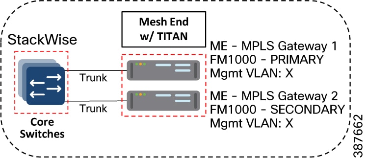
Catalyst-9500 StackWise Virtual High-Availability
Cisco StackWise Virtual is a two-node solution providing a Unified Control Plane Architecture by assigning one switch as active and the other as a hot-standby. Both the switches play an active role when it comes to data forwarding. Two Cat-9500 switches are connected together using a StackWise Virtual Link (SVL). The SVL helps bring the two switches together forming a single logical switch. Both the switches can be managed as a single entity. Since the control plane, management plane, and data plane are integrated, the system behaves as a single switch. The advantage of configuring the switches in a StackWise pair is that it provides hardware redundancy and fast failover.
FM1000 Mesh End Redundancy and TITAN Fast-Failover
It is highly recommended to purchase and apply the TITAN high-availability plug-ins for a pair of redundant FM-1000 Mesh Ends to be used within the AGV/AMR deployment.
Once configured, TITAN is completely autonomous and ensures stable and reliable connectivity without the need for any human intervention. If data exchange ceases because of the failure of the primary mesh-end device, TITAN will detect the failure and re-route the traffic through the designated secondary device, re-establishing connectivity within a maximum of 500 mSec. When the failed primary mesh end device comes back online, the secondary mesh end device automatically reverts to its standby role.
It is highly recommended to power each of the FM1000 gateways using a different power source and connect them to different switches within the 9500 StackWise pair. This provides protection against power outages and switch hardware failure.
Primary election
All CURWB units connected to the same wired broadcast domain and configured with the same passphrase perform a distributed primary election process every few seconds. The primary unit constitutes an edge point of the Fluidmesh MPLS network, i.e. a device where the user traffic may enter or leave the mesh. Secondary units act as MPLS relay points.
For each neighbor, the algorithm computes a precedence value based on the role of unit (mesh-end or mesh-point) and its mesh-ID. Mesh-ends are assigned a higher priority than mesh-points and, among the same priority, the unit having the lowest mesh-ID is preferred. The election mechanism relies on a dedicated signaling protocol which constantly runs in the network and it guarantees that all units elect the same primary.
Mesh-end Failover
During normal operation, the primary and secondary mesh-ends constantly communicate to inform each other about their status and to exchange network reachability information. In particular, the primary periodically sends updates to the secondary regarding its internal forwarding table and multicast routes.
Primary Mesh-end Failure
When the primary mesh-end unit fails for any reason, a timeout expires on the secondary after not receiving keepalives for a configurable interval (typically between 50 - 200 mSec). At that point, the secondary becomes the new active mesh-end taking over the role of primary and it executes the following actions:
1.![]() Issues a Primary Change command to inform all other units on the same wired network that the primary has changed. The message is propagated to mobile units as well using an efficient distribution protocol.
Issues a Primary Change command to inform all other units on the same wired network that the primary has changed. The message is propagated to mobile units as well using an efficient distribution protocol.
2.![]() Updates the internal MAC and MPLS forwarding tables. This step is performed using a patented fast-rerouting technique that provides seamless performance.
Updates the internal MAC and MPLS forwarding tables. This step is performed using a patented fast-rerouting technique that provides seamless performance.
3.![]() Sends gratuitous ARPs for the on-board devices on its ethernet/fiber port. This forces the network switch to update its MAC forwarding table (CAM) so that it will send traffic for on-board destinations through the port connected to the new primary.
Sends gratuitous ARPs for the on-board devices on its ethernet/fiber port. This forces the network switch to update its MAC forwarding table (CAM) so that it will send traffic for on-board destinations through the port connected to the new primary.
When the other units receive the Primary Change command from the secondary, they perform the internal seamless fast-rerouting procedure (step 2), so that the traffic can be immediately forwarded with no additional delay and signaling required. This allows for fast network reconvergence, with an effective end-to-end service disruption below 500 mSec.
Primary Mesh-End Recovery
When the primary mesh-end is recovered, it initially scans the network for the presence of an active secondary mesh-end. If the detection is positive, then the unit enters an inhibition mode where-in the secondary remains the current edge point of the infrastructure for a certain amount of time (default 70 seconds). During this grace period, the primary receives updates from the currently active secondary mesh-end and acquires full knowledge about the state of the network. After that, it switches to being the primary node following the same procedure described above for failover.
Global Gateway Redundancy
Just like the Mesh-end gateways, the Global gateways within a L3 Fluidity design are deployed as a redundant pair. Each global gateway should be configured with the TITAN high-availability plug-in to enable fast convergence in case of a hardware or network link failure.
L2TP Redundancy
With the system in normal condition (all devices up and running), this is the expected scenario between the global gateways and each L3 Fluidity trackside cluster:
■![]() L2TP Tunnel between Primary Global Gateway and Primary Mesh End – CONN
L2TP Tunnel between Primary Global Gateway and Primary Mesh End – CONN
■![]() L2TP Tunnel between Primary Global Gateway and Secondary Mesh End – IDLE
L2TP Tunnel between Primary Global Gateway and Secondary Mesh End – IDLE
■![]() L2TP Tunnel between Secondary Global Gateway and Primary Mesh End – IDLE
L2TP Tunnel between Secondary Global Gateway and Primary Mesh End – IDLE
■![]() L2TP Tunnel between Secondary Global Gateway and Secondary Mesh End – IDLE
L2TP Tunnel between Secondary Global Gateway and Secondary Mesh End – IDLE
Global Gateway Failure: In case of failure of Primary Global Gateway, the L2TP tunnels between itself and the primary Mesh End of each cluster will become IDLE, while the L2TP tunnels between the secondary Global Gateway (elected the new Primary) and the primary Mesh End of each cluster will become CONN.
Mesh End Failure: In case of failure of Primary Mesh End in a cluster, the L2TP tunnels between itself and the primary Global Gateway will become IDLE, while the L2TP tunnels between the secondary Mesh End (elected the new Primary) and the primary Global Gateway will become CONN.
CURWB Access Layer - Fast Convergence on Failure
Link Backhaul Check – Handoff Inhibition
Leveraging the Link Backhaul Check feature, an access radio unit detects a carrier loss on its Ethernet/Fiber port hence losing its ability to deliver mobility traffic to the mesh-end. The affected radio unit immediately advertises its status as ‘Unavailable’, by transmitting a ‘handoff inhibition’ message over the wireless channel. Upon receiving the ‘handoff inhibition’ message any existing mobile radios connected to this particular radio unit will try and search for another access radio to connect to. All mobile radio units currently connected to this unavailable access radio will find and connect to an alternative access radio unit within a few hundred milliseconds, typically within < 400 mSec. Also any handoff attempts from any other mobile radios to this affected access radio will be rejected. It is highly recommended to enable the Link Backhaul Check feature on the access radios within an AGV/AMR deployment.
Figure 32 Link Backhaul Check – Handoff Inhibition
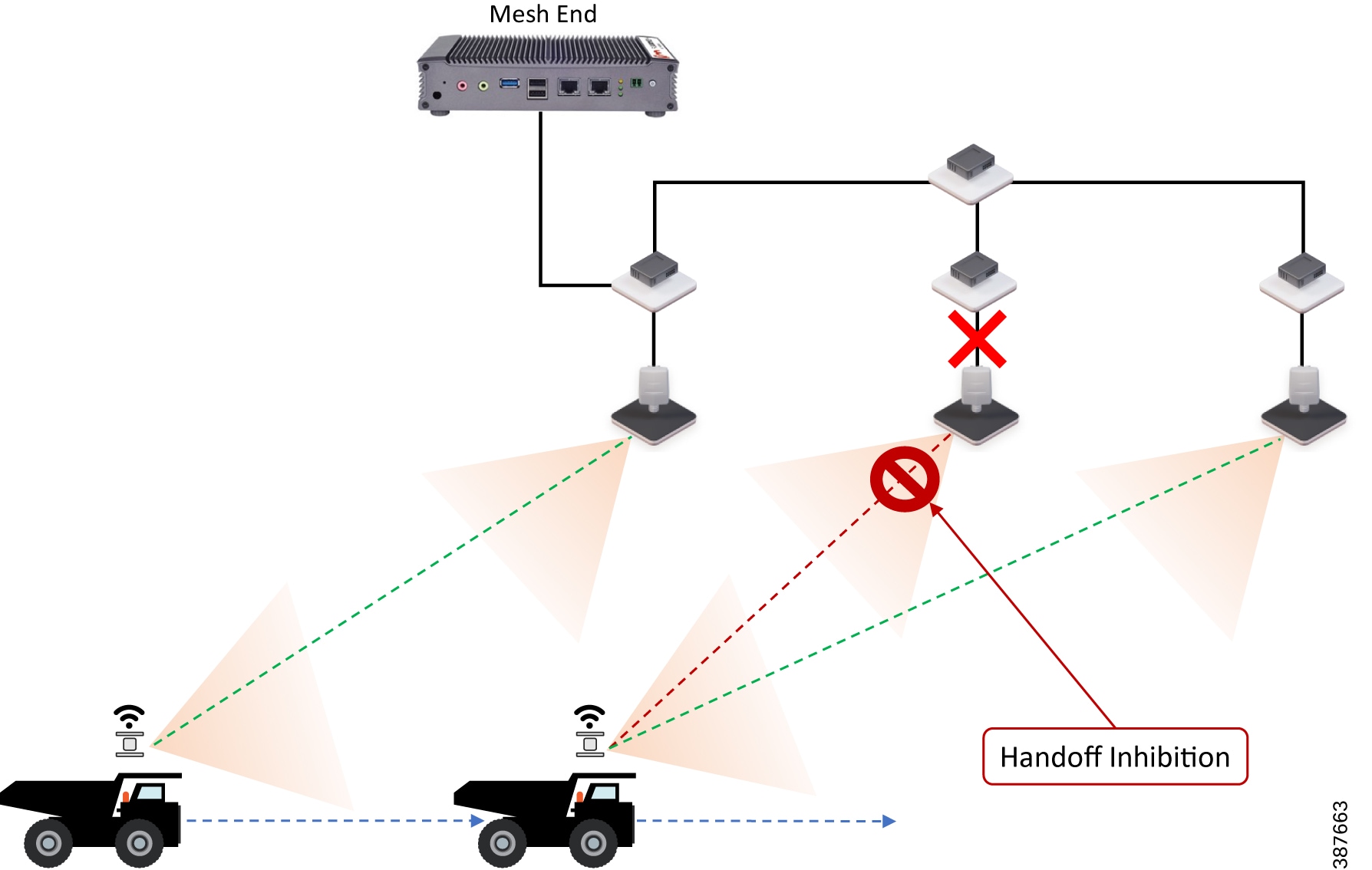
In the figure above it is shown that the link between the infrastructure radio and the directly connected switch is down. Assuming that the radio is not powered using PoE but via an external power source the radio is still up and providing good wireless connectivity to the vehicles. However since the wired link is down and the radio is not able to forward traffic to the wired network, the radio goes into handoff inhibition mode and will reject any handoff attempts from vehicles.
Mesh-End Backhaul Check – Handoff Inhibition
Leveraging the Mesh-End Backhaul Check feature, an access radio unit detects that it is not able to reach the active mesh end. This failure is triggered when L2 MAC reachability is lot to the active mesh end for 250 mSec. The affected radio unit immediately advertises its status as ‘Unavailable’, by transmitting a ‘handoff inhibition’ message over the wireless channel. Upon receiving the ‘handoff inhibition’ message any existing mobile radios connected to this particular radio unit will try and search for another access radio to connect to. All mobile radio units currently connected to this unavailable access radio will find and connect to an alternative access radio unit within a few hundred milliseconds, typically within < 400 mSec. Also any handoff attempts from any other mobile radios to this affected access radio will be rejected. It is highly recommended to enable the Mesh-End Backhaul Check feature on the access radios.
Figure 33 Mesh-End Backhaul Check – Handoff Inhibition
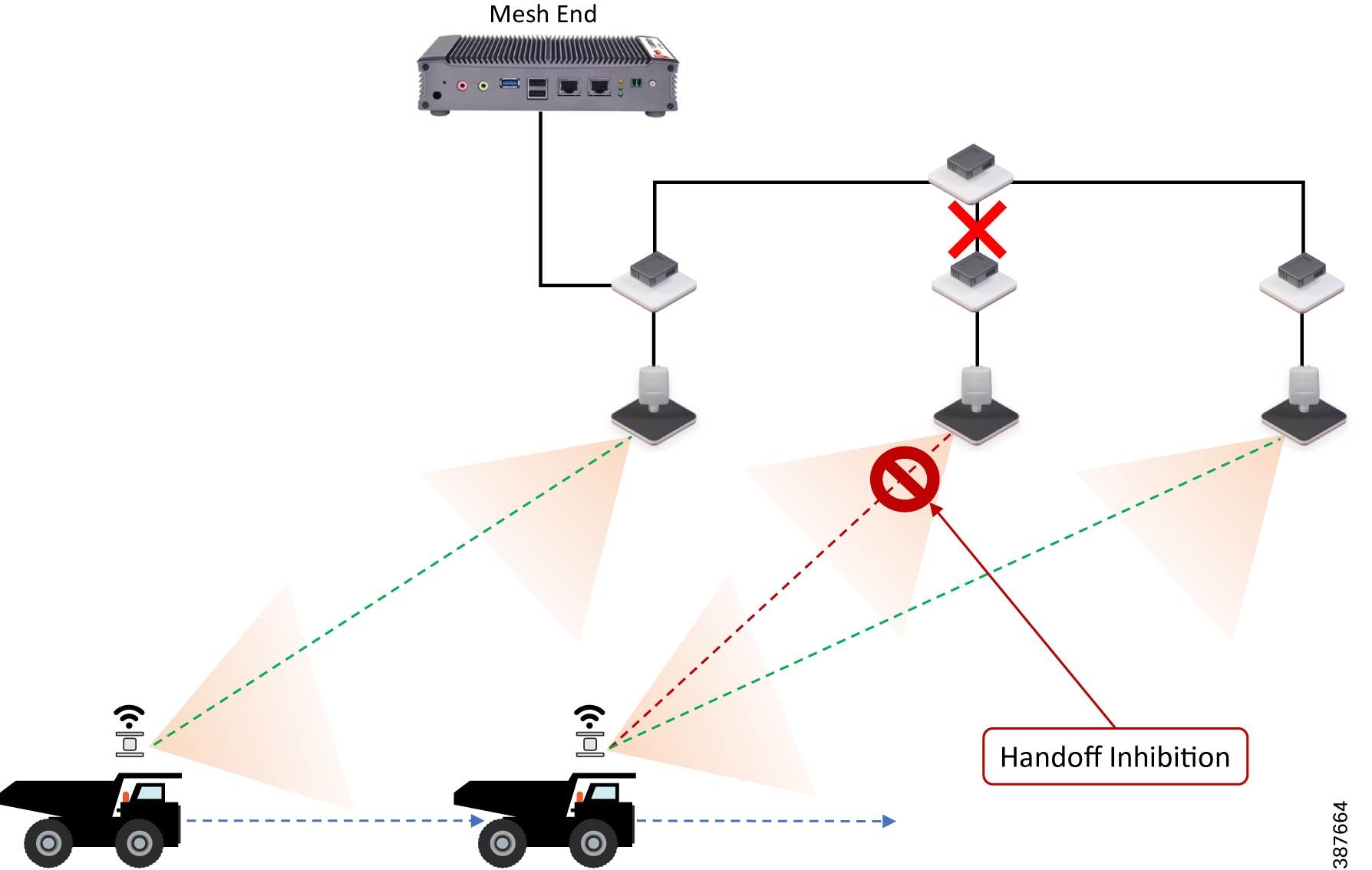
In the figure above it is shown that the directly connected switch of a CURWB access loses its wired connectivity to the core switch, the infrastructure radio is powered on and providing good coverage and connectivity to vehicles but since the radio is not able to forward traffic to the mesh end located within the control room, it will go into handoff inhibition mode and reject any handoff attempts from vehicles.
On-board Radio Redundancy - Failover and Recovery
TITAN high-availability is not just applicable for mesh ends. In scenarios where two CURWB radios are deployed on-board a vehicle, the two radios can paired-up together by applying the TITAN plug-in to provide hardware redundancy.
The on-board failover process is very similar to the mesh-end one and it encompasses the same steps described in the previous section by just swapping the infrastructure and the on-board networks.
The main difference is that when a mobile unit becomes the new primary after a failure or recovery event, it executes the following additional actions:
1.![]() If the automatic vehicle ID feature is enabled, it computes a new Vehicle ID and forces the update on all the on-board units accordingly.
If the automatic vehicle ID feature is enabled, it computes a new Vehicle ID and forces the update on all the on-board units accordingly.
2.![]() It performs a forced handoff procedure instead of sending a Primary Switch command to update the infrastructure network even more efficiently.
It performs a forced handoff procedure instead of sending a Primary Switch command to update the infrastructure network even more efficiently.
CURWB Network Deployment Guidance
CIP/PROFINET Support on CURWB
In order for the CURWB radio to support CIP or PROFINET, the corresponding plug-in must be applied on all of the CURWB devices within the deployment. Enabling QoS for CIP Traffic
Enabling QOS for CIP Traffic
■![]() CIP and PROFINET traffic need to be classified and marked with a QoS value of CS6 in order to be put in the queue with packet aggregation disabled.
CIP and PROFINET traffic need to be classified and marked with a QoS value of CS6 in order to be put in the queue with packet aggregation disabled.
■![]() An important point to note is that since packet aggregation is not used for traffic marked with CS6 there is a hit to the throughput especially for smaller size packets (typical for PLC to PLC and PLC to I/O traffic) due to the increased overhead per packet. However, this should not be an issue since the throughput requirements for AGV/AMR requirements are not high.
An important point to note is that since packet aggregation is not used for traffic marked with CS6 there is a hit to the throughput especially for smaller size packets (typical for PLC to PLC and PLC to I/O traffic) due to the increased overhead per packet. However, this should not be an issue since the throughput requirements for AGV/AMR requirements are not high.
Cisco IE switch QoS Configuration for CIP
The Cisco IE3x00 switch supports Quality of Service (QoS) which allows a certain type of traffic to be treated differently at the expense of others, so the performance of high priority traffic such as TOS can be assured. Classification and marking are the first steps to implement QoS. Classification differentiates traffic type by examining the packet header. A packet can be classified based on the DSCP, the COS, and the IP precedence value in the header. It can also be classified with VLAN ID and Access control list (ACL).
Classification and marking is recommended at the entry point of the network. After the traffic is classified, certain QoS features can be applied in the policy map depending on the ingress or egress direction of the traffic. In the case of input policy applied to ingress traffic, the IE3x00 can be configured either to trust the marking from the client device or set it to a different value based on business requirements; for output policy that is applied to egress traffic, you can assign a percentage of bandwidth, shape transmission to certain rate, or set a queue-limit for specific traffic type. IE3x00 supports multiple queueing models such as class-based weighted fair queuing (CBWFQ), and priority queuing.
Below is a sample configuration showing QoS classification and marking for CIP traffic on a Cisco IE3x00 switch:
Configuring PROFINET on Cisco IE Switches
You can use either the SIMATIC STEP7 or TIA Portal Automation application on the I/O supervisor, or you can use the Cisco IOS software to configure PROFINET on the switch.
After you enable PROFINET, Link Layer Discovery Protocol (LLDP) is automatically enabled on the switch because PROFINET relies on LLDP to fully function. If you disable PROFINET, you can enable or disable LLDP as needed.
Default Configuration
PROFINET is enabled by default on all switch ports. The default configuration is enabled on VLAN 1, but you can change it to another VLAN ID. Out of the box, VLAN 1 is shut down. When bringing up an out-of-the-box switch for PROFINET, unshut VLAN 1 as follows:
Enabling PROFINET
To enable PROFINET, follow these steps:
Step1 Enter global configuration mode:
Step2 Enable PROFINET on the switch:
Step3 (Optional) Set the PROFINET device identifier (ID) by using the Cisco IOS software:
The maximum length of the ID string can be 240 characters. The only special characters allowed are period (.) and hyphen (-), and they are allowed only in specific positions within the ID string. The ID can have multiple labels within the string. Each label can be from 1 to 63 characters, and labels must be separated by a period (.). The final character in the string must not be zero (0).
Step4 (Optional) Change the VLAN number. The default VLAN number is 1. The VLAN ID range is from 1 to 4096. One PROFINET VLAN is supported per switch.
Note: You must create a VLAN before assigning a new VLAN to PROFINET if you are using a nondefault VLAN.
Step5 Return to privileged EXEC mode:
Step7 (Optional) Save your entries in the configuration file:
Cisco IE Switch QoS configuration for PROFINET
The switch prioritizes PROFINET traffic using a quality of service (QoS) policy, which is configured when the switch goes into Connected mode. The default configuration for PROFINET QoS is shown here:
To change the QoS policy, for example, for a PROFINET QoS configuration that works regardless of the VLAN tagging on interfaces, it is best to match on PROFINET Ethertype.
COS is a value found in the VLAN tag of an Ethernet frame. To match on COS value, the PROFINET Ethernet frames must have a VLAN tag associated with them. If PROFINET Ethernet frames are being forwarded through the network without VLAN tags, as shown above, then this QoS policy may not work as expected.
Enabling QoS on CURWB Radios
It is crucial that PLC traffic (CIP, CIP Safety, PROFINET, PROFIsafe) is tagged with CS6 on the vehicle and wayside switches. CURWB radios use the traffic priority tag to determine which traffic gets sent out first over the air.
By default, QoS processing is disabled on FM Radios.
Figure 34 Enabling CURWB QoS support in RACER UI
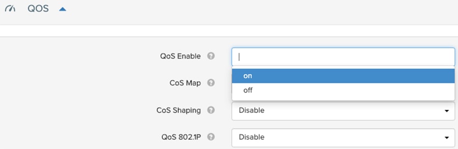
To enable QoS processing execute the following commands on each radio CLI:
Verifying QoS Enabled on CURWB Radios
After the CURWB radio reboots execute the following command on the CURWB radio CLI ‘show running-config’ or ‘qos’ to verify if QoS has been successfully enabled.
Figure 35 Verifying QoS enabled on CURWB radios

Tweaking the Packet Retry Delay and Fallback values on CURWB
■![]() ‘Retry Delay’ – sets the maximum delay for retries.
‘Retry Delay’ – sets the maximum delay for retries.
■![]() ‘Fallback’ – Number of times the radio should try and retransmit un-ACKed packets. After each transmission attempt, the counter decrements by ‘1’. The next transmission is attempted at a lower MCS rate compared to the previous failed transmission.
‘Fallback’ – Number of times the radio should try and retransmit un-ACKed packets. After each transmission attempt, the counter decrements by ‘1’. The next transmission is attempted at a lower MCS rate compared to the previous failed transmission.
■![]() Since the AGV control application is latency sensitive we decided to lower the ‘Retry Delay’ to a value of 8 mSec. So, in case a packet transmission fails (no ACK received), the next packet retry attempt is triggered quickly after a wait of only 8 mSec.
Since the AGV control application is latency sensitive we decided to lower the ‘Retry Delay’ to a value of 8 mSec. So, in case a packet transmission fails (no ACK received), the next packet retry attempt is triggered quickly after a wait of only 8 mSec.
■![]() For the number of ‘Fallback’ attempts we again lowered this value. We tested with a values of ‘2’ and ‘3’. We recommend using a value of ‘3’, since we observed the best results when using this value. Since the AGV control application is latency sensitive we don’t want to attempt re-transmission of the packet too many times since this increases latency. After ‘3’ retry attempts, mark the packet as failed and move on.
For the number of ‘Fallback’ attempts we again lowered this value. We tested with a values of ‘2’ and ‘3’. We recommend using a value of ‘3’, since we observed the best results when using this value. Since the AGV control application is latency sensitive we don’t want to attempt re-transmission of the packet too many times since this increases latency. After ‘3’ retry attempts, mark the packet as failed and move on.
Key Recommendations for a CIP Safety deployment
■![]() Configure a wireless ‘retry delay’ of 8 mSec on the Infra and AGV radios.
Configure a wireless ‘retry delay’ of 8 mSec on the Infra and AGV radios.
■![]() Configure a ‘fallback’ limit of ‘3’ on the Infra and AGV radios.
Configure a ‘fallback’ limit of ‘3’ on the Infra and AGV radios.
■![]() We observed timeouts between the wired PLC and wireless I/O when the RSSI fell below 60 dBm. Hence it is highly recommended to perform a site survey to ensure that appropriate coverage is provided along all paths AGVs are expected to traverse and an RSSI value better than 60 dBm is maintained.
We observed timeouts between the wired PLC and wireless I/O when the RSSI fell below 60 dBm. Hence it is highly recommended to perform a site survey to ensure that appropriate coverage is provided along all paths AGVs are expected to traverse and an RSSI value better than 60 dBm is maintained.
■![]() Ensure that the TX. Power from the Infra Radios to the AGV radio and vice-versa are symmetric. This way the Infra Radios have good downstream RSSI to the AGVs and the AGVs have good upstream RSSI to the Infra Radios.
Ensure that the TX. Power from the Infra Radios to the AGV radio and vice-versa are symmetric. This way the Infra Radios have good downstream RSSI to the AGVs and the AGVs have good upstream RSSI to the Infra Radios.
■![]() For a CIP Wired PLC to a CIP Wireless IO Request Packet Interval (RPI) we recommend using a value > 10 mSec.
For a CIP Wired PLC to a CIP Wireless IO Request Packet Interval (RPI) we recommend using a value > 10 mSec.
■![]() For a CIP Wired PLC to a CIP Wireless IO Request Timeout Multiplier we recommend using a value of 4.
For a CIP Wired PLC to a CIP Wireless IO Request Timeout Multiplier we recommend using a value of 4.
Perform an RF Site Survey
Each facility can be different and bring unique challenges to implementing a wireless system. How a facility was constructed and arranged will change where devices must be placed because different surface finishes and geometries reflect and dampen radio waves. During the site survey, wireless equipment should be placed around the site to measure signal strength based on the placement and the number of wireless devices. It is mandatory to perform site surveys to determine the RF coverage across the intended AGV/AMR traversal path. AP density and AP placement might need to be tweaked accordingly to accommodate for any challenging RF locations.
Configuration and Provisioning Best Practices
■![]() To eliminate packet fragmentation, the MTU on the switches must be increased to at least 15448 bytes. CURWB devices use MPLS for encapsulating Ethernet frames, resulting in a need for the larger than default MTU size of 1500 bytes.
To eliminate packet fragmentation, the MTU on the switches must be increased to at least 15448 bytes. CURWB devices use MPLS for encapsulating Ethernet frames, resulting in a need for the larger than default MTU size of 1500 bytes.
■![]() It is critical to know the time-out setting for the vehicle and the AGV/AMR control systems, so that MAC tuning of radios is done to meet the needs of the application. Radio configurations can be adjusted and optimized to support specific timeout requirements (for e.g., the number of re-transmissions before a packet is dropped).
It is critical to know the time-out setting for the vehicle and the AGV/AMR control systems, so that MAC tuning of radios is done to meet the needs of the application. Radio configurations can be adjusted and optimized to support specific timeout requirements (for e.g., the number of re-transmissions before a packet is dropped).
■![]() The number of vehicles will also have an impact on the wireless network due to contention between different vehicle radios. MAC tuning is required to address the contention.
The number of vehicles will also have an impact on the wireless network due to contention between different vehicle radios. MAC tuning is required to address the contention.
■![]() Knowing what PLC system is being used also helps with the MAC tuning process. Common PLC systems are Rockwell (CIP/CIP Safety) and Siemens (PROFINET/PROFISafe). Some systems use a broadcast approach from the control PLC to the vehicle PLC.
Knowing what PLC system is being used also helps with the MAC tuning process. Common PLC systems are Rockwell (CIP/CIP Safety) and Siemens (PROFINET/PROFISafe). Some systems use a broadcast approach from the control PLC to the vehicle PLC.
■![]() CIP or PROFINET software plug-ins are needed on the CURWB devices to support whichever industrial protocol is being used.
CIP or PROFINET software plug-ins are needed on the CURWB devices to support whichever industrial protocol is being used.
■![]() Another important plug-in that may be needed is AES, for encrypting the data flows between the vehicles radios to the wayside radios and vice-versa.
Another important plug-in that may be needed is AES, for encrypting the data flows between the vehicles radios to the wayside radios and vice-versa.
Deployment Guidance and Best Practices
■![]() Understand the technical requirements and timeouts for the industrial or industrial safety protocol in use and design and deploy the solution accordingly to meet or exceed those requirements
Understand the technical requirements and timeouts for the industrial or industrial safety protocol in use and design and deploy the solution accordingly to meet or exceed those requirements
■![]() Perform on-site RF spectrum analysis to identify and allocate clean RF channel for the CURWB deployment
Perform on-site RF spectrum analysis to identify and allocate clean RF channel for the CURWB deployment
■![]() For most AGV/AMR applications a 20-MHz wide channel is sufficient
For most AGV/AMR applications a 20-MHz wide channel is sufficient
■![]() Perform an RF site survey and tweak the design and AP deployment accordingly to ensure optimal coverage along the AGV/AMR traversal path
Perform an RF site survey and tweak the design and AP deployment accordingly to ensure optimal coverage along the AGV/AMR traversal path
■![]() Install 3-dB Omni-directional antennas on both the Wayside and Vehicle Radios.
Install 3-dB Omni-directional antennas on both the Wayside and Vehicle Radios.
■![]() For Warehouses which have long lanes with tall shelves on either sides, directional antennas installed on the Wayside radios and pointed in slightly downward direction can be used to provide coverage along the lane(s).
For Warehouses which have long lanes with tall shelves on either sides, directional antennas installed on the Wayside radios and pointed in slightly downward direction can be used to provide coverage along the lane(s).
■![]() Challenging RF obstacles need to be considered during Wayside AP placement. Roaming can fail if the vehicle radio does not have enough time to properly scan for neighboring APs. Turning the corner around a metal or high-attenuation barrier which cases the RF environment to change very rapidly can be problematic without proper AP placement.
Challenging RF obstacles need to be considered during Wayside AP placement. Roaming can fail if the vehicle radio does not have enough time to properly scan for neighboring APs. Turning the corner around a metal or high-attenuation barrier which cases the RF environment to change very rapidly can be problematic without proper AP placement.
■![]() Design the wireless cells such that the Cell edge provides a min RSSI of 60dBm
Design the wireless cells such that the Cell edge provides a min RSSI of 60dBm
■![]() Avoid RF Ping Pong Zones where the AGV/AMR is at the edge of two wireless cells and hops between them
Avoid RF Ping Pong Zones where the AGV/AMR is at the edge of two wireless cells and hops between them
■![]() It is highly recommended to deploy a dedicated CURWB network to support the AGV/AMR application
It is highly recommended to deploy a dedicated CURWB network to support the AGV/AMR application
■![]() Provide a 20% RF coverage overlap between adjacent wireless cells
Provide a 20% RF coverage overlap between adjacent wireless cells
■![]() Ensure that we have symmetric Transmit power in both the downstream (Wayside AP to Vehicle AP) and upstream (Vehicle AP to Wayside AP)
Ensure that we have symmetric Transmit power in both the downstream (Wayside AP to Vehicle AP) and upstream (Vehicle AP to Wayside AP)
■![]() Ensure that the CIP/PROFINET traffic is marked with the correct QoS (DSCP/CoS). Ensure that the QoS mapping is preserved throughout the end-to-end flow across both the wireless and wired network.
Ensure that the CIP/PROFINET traffic is marked with the correct QoS (DSCP/CoS). Ensure that the QoS mapping is preserved throughout the end-to-end flow across both the wireless and wired network.
■![]() Avoid configuring Dynamic Frequency Selection (DFS) channels on the 5 GHz band (channels 52 to 140) to prevent interference from radar signals
Avoid configuring Dynamic Frequency Selection (DFS) channels on the 5 GHz band (channels 52 to 140) to prevent interference from radar signals
■![]() Adjust the retry-delay and the number of retry attempts to satisfy the application latency requirement
Adjust the retry-delay and the number of retry attempts to satisfy the application latency requirement
■![]() Reserve 20 percent of bandwidth for HMI and maintenance traffic such as web page diagnostic, programming tools etc.
Reserve 20 percent of bandwidth for HMI and maintenance traffic such as web page diagnostic, programming tools etc.
■![]() Because missed or delayed packets can lead to the safety function being activated, we need to ensure that CIP Safety packets are making it across the wireless network as expected. In the Logix Designer application, you may want to experiment with changing the Advanced Connection Reaction Time Limit Configuration during the commissioning process. This can help determine the cause of nuisance faults if they are occurring during testing. The more aggressive the settings are (lower the timeout values), the more likely you are to see packet loss faults generated due to delayed or lost packets. Remember that changes to these advanced settings directly impact the connection reaction time limit and the overall safety function reaction time.
Because missed or delayed packets can lead to the safety function being activated, we need to ensure that CIP Safety packets are making it across the wireless network as expected. In the Logix Designer application, you may want to experiment with changing the Advanced Connection Reaction Time Limit Configuration during the commissioning process. This can help determine the cause of nuisance faults if they are occurring during testing. The more aggressive the settings are (lower the timeout values), the more likely you are to see packet loss faults generated due to delayed or lost packets. Remember that changes to these advanced settings directly impact the connection reaction time limit and the overall safety function reaction time.
■![]() Anytime the AGV/AMR traversal path is modified, a new site-survey will need to be performed especially to ensure that we have adequate RF coverage over the newly introduced path.
Anytime the AGV/AMR traversal path is modified, a new site-survey will need to be performed especially to ensure that we have adequate RF coverage over the newly introduced path.
Best Practices for Rollout
■![]() FM4500 Mobi radios need a nominal power of 10 Watts, with a maximum of 20 Watts at 48V DC. This can be supplied by:
FM4500 Mobi radios need a nominal power of 10 Watts, with a maximum of 20 Watts at 48V DC. This can be supplied by:
–![]() A standard IEEE 802.3at switch, through the LAN1/PoE port
A standard IEEE 802.3at switch, through the LAN1/PoE port
–![]() A 48V DC power supply (not included), through the DC-IN port
A 48V DC power supply (not included), through the DC-IN port
■![]() For reliable connectivity and proper grounding of the radio, shielded M12 cables and connectors must always be used.
For reliable connectivity and proper grounding of the radio, shielded M12 cables and connectors must always be used.
■![]() If cables are used to connect antennas to a radio, keep the antennas a minimum of 3 inches (8 cm), and a maximum of 60 inches (150 cm) apart
If cables are used to connect antennas to a radio, keep the antennas a minimum of 3 inches (8 cm), and a maximum of 60 inches (150 cm) apart
■![]() The CURWB FM-POE-LOW-48 PoE injector allows the FM4500 Mobi radio to be powered using a low voltage power source. It is an ideal solution in vehicles that use batteries. The injector can accept DC power input voltages from 9V DC to 36V DC and produce output voltage of 48V DC passive, with a maximum power output of 17 W.
The CURWB FM-POE-LOW-48 PoE injector allows the FM4500 Mobi radio to be powered using a low voltage power source. It is an ideal solution in vehicles that use batteries. The injector can accept DC power input voltages from 9V DC to 36V DC and produce output voltage of 48V DC passive, with a maximum power output of 17 W.
■![]() It is highly recommended to mount antennas vertically and not horizontally. Avoid mounting antennas close to metal beams. This will result in unwanted signal reflections.
It is highly recommended to mount antennas vertically and not horizontally. Avoid mounting antennas close to metal beams. This will result in unwanted signal reflections.
CURWB Tools for Live RF Analysis and Troubleshooting
FLUIDSTATS and FLUIDREC
FluidSTATS and FluidREC are excellent tools within the CURWB portfolio that can be used extensively within the initial deployment and troubleshooting phase. They are very helpful in understanding and fine tuning the RF environment to meet application requirements. They provide detailed graphs showing the RSSI, SNR, PER, LER and the handoffs occurring as the vehicle travels across various wayside APs.
This section describes how to install and operate the FluidSTATS and FluidREC products. Screenshots shown in this section are explanatory examples and may be different from the ones that appear when you run the software.
Fluidity Statistics Protocol
Mobile radios must be configured to send telemetry data to the host PC running FluidSTATS. Mobile radio units running Fluidity support the transmission of a network data stream to provide real-time telemetry statistics regarding the status and the performance of the vehicular connection to listening applications.
The stream is generated by the primary mobile unit of a vehicle at a rate of 4 packets per second (one packet every 250 mSec). It consists of a flow of UDP packets transmitted to a specified IP address and port. To enable the transmission of the stream, run the following commands on the CLI of the mobile primary unit:
If the destination port is not specified, the default value of 30000 is used. The source port is set to 647 and the source IP address of the packets is the IP address of the mobile primary unit.
FluidSTATS and FluidREC Software Download & Installation
Download the latest version of FluidSTATS and FluidREC for your operating system from partners.fluidmesh.com. Both software are compiled for: Windows, MAC, Linux operating systems. Once downloaded, un-zip the archive file. Both software can be opened by double-clicking on their executable files.
FluidSTATS
FluidSTATS allows live monitoring of the wireless network through an easy and accessible user interface. FluidSTATS is the recommended software during the commissioning phase of a project. While connected to a GPS antenna mounted on board a vehicle FluidSTATS can track the main parameters along the drive path to create a site survey providing an idea of the RF coverage.
Open the GUI by double-clicking on the corresponding executable file. Several options are available within the FluidSTATS GUI as depicted in the figure below.
The figure below depicts the basic configuration of the system. This settings page can be displayed by clicking on ‘Preferences’ button or in the main top menu. The following parameters must be specified for the normal operations:
■![]() GPS serial device to be used to gather GPS position during the test (the GPS external device must be connected and configured before opening the software)
GPS serial device to be used to gather GPS position during the test (the GPS external device must be connected and configured before opening the software)
■![]() Serial Port Speed of the GPS device (typical speed is 4800 or 9600 baud)
Serial Port Speed of the GPS device (typical speed is 4800 or 9600 baud)
■![]() UDP port used by the radio to send telemetry packets for the testing (default is 30000)
UDP port used by the radio to send telemetry packets for the testing (default is 30000)
■![]() Multicast Group telemetry packets from the radio can be configured for multicast destination address
Multicast Group telemetry packets from the radio can be configured for multicast destination address
■![]() Multicast Interface if in use, the network interface to receive multicast traffic can be specified
Multicast Interface if in use, the network interface to receive multicast traffic can be specified
Figure 37 FluidSTATS Application Settings
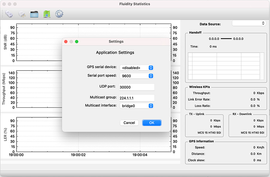
After the system is properly configured and the mobile unit is under coverage of the wireless access network several parameters can be monitored in real time including: the SNR received from each access radio unit, Link Error Rate (LER), Packet Error Rate (PER), Throughput, Handoff time, MCSs and GPS position as described in detail in the following sections.
FluidSTATS Data Source
On the top-right side of the pane, there is a drop-down box that is used to select the Data Source. The Data Source list will automatically be populated with any radio FluidSTATS is currently receiving data from. The Data Source will show as the IP address of the radio.
Figure 38 FluidSTATS Data Source
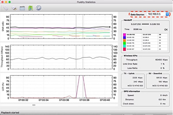
FluidSTATS Handoff
The Handoff section shows the Mesh IDs of the APs with the strongest signal. The radio Mesh ID in bold is the active and current AP selected by the vehicle. It also gives an indication of the “control plane” handoff time, in milliseconds, and whether the latest handoff was successful. Please note that, thanks to the Make-Before-Break Fluidity technology, the handoff at the ‘data plane’ is seamless and cannot be reported. Therefore, the handoff time reading is only meant to detect potential issues related to the coverage or to external interference.
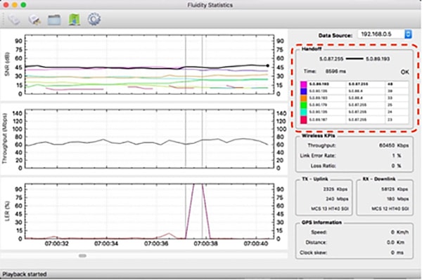
FluidSTATS Wireless KPIs
The Instantaneous Throughput (in Kbps or Mbps) is reported on the right-hand side of the chart. Two additional indicators for the Link Error Rate and the Loss Ratio are shown. The Link Error Rate (LER) is a synthetic KPI indicator that is a ratio of the un-acknowledged transmitted packets over the total transmitted packets. Un-acknowledged packets are typically retransmitted several times at the MAC layer during normal transmission operations.
The Loss Ratio (Packet Error Rate – PER) represents the ratio between the number of packets dropped and the total number of packets transmitted. Transmitted packets are dropped when the maximum number of MAC layer retransmissions allowed is exceeded.
The tool also reports the split of the uplink TX throughput (traffic from vehicle to wayside) and downlink RX throughput (traffic from wayside to vehicle) as well as Modulation speed (MCS) and MCS scheme (ex: MCS 14 HT40 LGI => Modulation and Coding Speed 14 with 40 MHz channel and Large Guard Intervals).
Figure 40 FluidSTATS Wireless KPIs
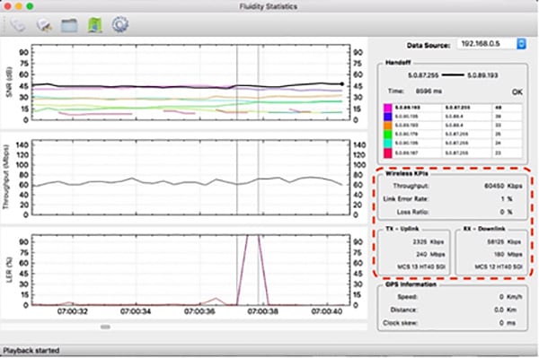
FluidSTATS GPS Information
An external USB GPS device can be connected and synced to FluidSTATS. The software will record and sync GPS data with the statistical information received from the wireless network.
Figure 41 FluidSTATS GPS Information
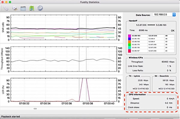
FluidSTATS SNR Plot
The SNR (Signal to Noise Ratio) plot shows the strongest signals as seen by the vehicle radio. The black line shows the signal of the AP connected to the vehicle radio and it is usually the upper envelop of the SNR lines. Vertical grey lines indicate the HANDOFFs the vehicle radio is making as the vehicle moves around.
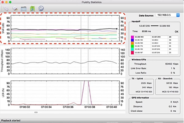
FluidSTATS Throughput
The Throughput plot shows the total aggregate throughput passing through the wireless interface of the radio on the vehicle. This throughput is measured at Layer 2 and therefore it has a slightly higher variability compared to the throughput measured at the application layer. The chart shows the Total Throughput: Uplink and Downlink summed up together.
Figure 43 FluidSTATs Throughput
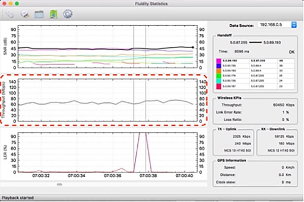
FluidSTATS LER
As described in the previous section, the Link Error Rate (LER) indicates the quality of the wireless transmission. The higher the LER, the higher the latency of the network. Usually, a LER lesser than 30% indicates that there is no visible degradation of network performance. Spikes in LER are typical in mobility scenarios as compared to fixed wireless infrastructure links.
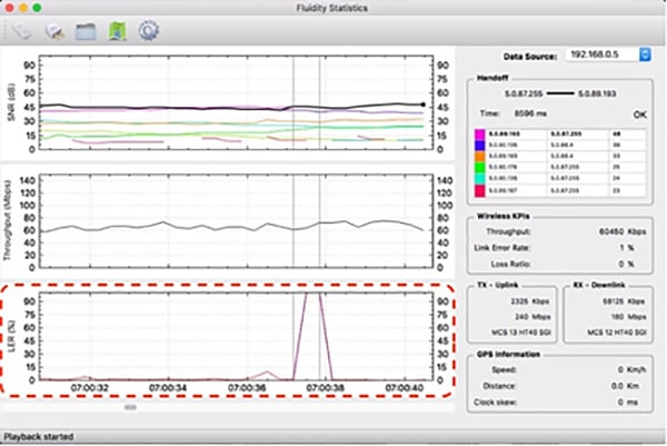
FluidREC
FluidREC is a stand-alone version of FluidSTATS and can be executed in the background allowing automatic monitoring and recording of the most important KPIs of the wireless network. FluidREC can be run on a small computer and left on-board on a vehicle for several days.
Several options are available to start and stop the recordings and split the record into multiple files. External GPS devices can be configured as well. Recorded files produced by FluidREC can be fed to FluidSTATS to playback the recorded data for offline analysis.
 Feedback