Overview

Overview

Cisco Application Policy Infrastructure Controller (APIC) release 5.3(1) added support for the Cisco APIC Server M4 and L4.

Cisco APIC Server M4 and L4 (APIC-SERVER-M4 and APIC-SERVER-L4)—Small form-factor (SFF) drives, with 10-drive HD back-plane front panel configuration.

  • Front-loading drive bays 1—10 support 2.5-inch SAS/SATA drives.

  • Optionally, front-loading drive bays 1 to 4 support 2.5-inch NVMe SSDs (with optional front NVMe cables.)

Considerations and Restrictions

The Cisco Application Policy Infrastructure Controller (APIC) Server M4 and L4 (APIC-SERVER-M4 and APIC-SERVER-L4) has the following consideratios and restrictions:

  • The role of the Dual 1-Gb/10-Gb Ethernet ports (LAN1 and LAN2) in previous Cisco APIC Generations is now moved to the mLOM card and Ports available on that card.

  • The mLom numbering doesn’t matter, APIC software creates a bond interface automatically.

  • There are two disks on the front panel, one of them serving as backup:

    • 1.6TB NVME in slot 1

    • 480GB SSD in slot 5


    Note


    There is also an internal 240G SSD boot disk.


External Features

This topic shows the external features of the server versions.

Cisco APIC M4 and L4 Server (SFF Drives) Front Panel Features

The following figure shows the front panel features of the small form-factor drive versions of the server.

Figure 1. Cisco APIC M4 and L4 Server (SFF Drives) Front Panel

1

Drive bays 1-10 support SAS/SATA hard disk drives (HDDs) and solid state drives (SSDs).

As an option, drive bays 1-4 can contain up to 4 NVMe drives in any number up to 4. Drive bays 5 through 10 support only SAS/SATA HDDs or SSDs.

APIC Server-M4 and L4 — Drive bays 1-10 supports 2.5-inch NVMe-only SSDs.

APIC-Server-M4 and L4: Drive bays 1 and 2 support NVMe PCIe SSDs.

2

Unit identification button/LED

3 Power button/power status LED

4

KVM connector

(used with KVM cable that provides one DB-15 VGA, one DB-9 serial, and two USB 2.0 connectors)

5

System LED cluster:

  • Fan status LED

  • System Status LED

  • Power supply status LED

  • Network link activity LED

  • Temperature status LED

Cisco APIC M4 and L4 Server Rear Panel Features

The rear panel features are the same for all versions of the server.

Figure 2. Cisco APIC M4 and L4 Server Rear Panel

1

PCIe slots

Following PCIe Riser combinations are available:

  • One half-height riser card in PCIe Riser 1

One of the following network interface cards should be installed in PCIe slot 1:

  • APIC-P-I8D25GF

  • APIC-P-ID10GC

  • APIC-PCIE-C25Q-04

  • Cisco VIC 1455

2

Power supply units (PSUs), two which can be redundant when configured in 1+1 power mode.

3

Modular LAN-on-motherboard (mLOM) card bay (x16 PCIe lane)

4

System identification button/LED

5

USB 3.0 ports (two)

6

Dedicated 1 GB Ethernet management port

7

COM port (RJ-45 connector)

8

VGA video port (DB-15 connector)

  • 10/25GbE ports on APIC-P-I8D25GF can be used as either 10G or 25G ports. All ports must have the same speed.

  • 25G connectivity between Cisco Application Centric Infrastructure (ACI) leaf and Cisco APIC M4/L4 with Intel NIC supports 25G fiber connection for the fabric link when APIC-P-I8D25GF network interface cards are used. For example, Cisco SFP-H25G-CU1M.

  • 25G connectivity between the Cisco ACI leaf and Cisco APIC M4/L4 can use either copper or fiber cables when APIC-PCIE-C25Q-04/Cisco VIC 1455 network interface cards are used.

    Please see the list of transceiver options: https://www.cisco.com/c/en/us/products/collateral/interfaces-modules/transceiver-modules/datasheet-c78-736950.html.

  • APIC-P-ID10GC supports 10G Base-T connectivity to Cisco ACI leaf nodes.

Status LEDS and Buttons

Front-Panel LEDs

Figure 3. Front Panel LEDs
Table 1. Front Panel LEDs, Definition of States

LED Name

States

1

SAS

SAS/SATA drive fault

Note

 
NVMe solid state drive (SSD) drive tray LEDs have different behavior than SAS/SATA drive trays.
  • Off—The hard drive is operating properly.

  • Amber—Drive fault detected.

  • Amber, blinking—The device is rebuilding.

  • Amber, blinking with one-second interval—Drive locate function activated in the software.

2

SAS

SAS/SATA drive activity LED

  • Off—There is no hard drive in the hard drive tray (no access, no fault).

  • Green—The hard drive is ready.

  • Green, blinking—The hard drive is reading or writing data.

1

NVMe

NVMe SSD drive fault

Note

 
NVMe solid state drive (SSD) drive tray LEDs have different behavior than SAS/SATA drive trays.
  • Off—The drive is not in use and can be safely removed.

  • Green—The drive is in use and functioning properly.

  • Green, blinking—the driver is initializing following insertion or the driver is unloading following an eject command.

  • Amber—The drive has failed.

  • Amber, blinking—A drive Locate command has been issued in the software.

2

NVMe

NVMe SSD activity

  • Off—No drive activity.

  • Green, blinking—There is drive activity.

3

Power button/LED

  • Off—There is no AC power to the server.

  • Amber—The server is in standby power mode. Power is supplied only to the Cisco IMC and some motherboard functions.

  • Green—The server is in main power mode. Power is supplied to all server components.

4

Unit identification

  • Off—The unit identification function is not in use.

  • Blue, blinking—The unit identification function is activated.

5

System health

  • Green—The server is running in normal operating condition.

  • Green, blinking—The server is performing system initialization and memory check.

  • Amber, steady—The server is in a degraded operational state (minor fault). For example:

    • Power supply redundancy is lost.

    • CPUs are mismatched.

    • At least one CPU is faulty.

    • At least one DIMM is faulty.

    • At least one drive in a RAID configuration failed.

  • Amber, 2 blinks—There is a major fault with the system board.

  • Amber, 3 blinks—There is a major fault with the memory DIMMs.

  • Amber, 4 blinks—There is a major fault with the CPUs.

6

Power supply status

  • Green—All power supplies are operating normally.

  • Amber, steady—One or more power supplies are in a degraded operational state.

  • Amber, blinking—One or more power supplies are in a critical fault state.

7

Fan status

  • Green—All fan modules are operating properly.

  • Amber, blinking—One or more fan modules breached the non-recoverable threshold.

8

Network link activity

  • Off—The Ethernet LOM port link is idle.

  • Green—One or more Ethernet LOM ports are link-active, but there is no activity.

  • Green, blinking—One or more Ethernet LOM ports are link-active, with activity.

    Note


    Intel NIC may display the following LED status:

    • Green—10Gbps

    • Yellow—10G speed with 10Gbase-SR-S transceiver

    • Yellow—5/2.5/1Gbps

    • Blinking green—transmitting or receiving data

    • Off—no link

9

Temperature status

  • Green—The server is operating at normal temperature.

  • Amber, steady—One or more temperature sensors breached the critical threshold.

  • Amber, blinking—One or more temperature sensors breached the non-recoverable threshold.

Rear-Panel LEDs

Figure 4. Rear Panel LEDs
Table 2. Rear Panel LEDs, Definition of States

LED Name

States

4

System Identification LED

  • Off— system is not operational.

  • Amber— critical error detected.

  • Green— system is operating normally.

Power supply status (one LED each power supply unit)

AC power supplies:

  • Off—No AC input (12 V main power off, 12 V standby power off).

  • Green, blinking—12 V main power off; 12 V standby power on.

  • Green, solid—12 V main power on; 12 V standby power on.

  • Amber, blinking—Warning threshold detected but 12 V main power on.

  • Amber, solid—Critical error detected; 12 V main power off (for example, over-current, over-voltage, or over-temperature failure).

DC power supplies:

  • Off—No DC input (12 V main power off, 12 V standby power off).

  • Green, blinking—12 V main power off; 12 V standby power on.

  • Green, solid—12 V main power on; 12 V standby power on.

  • Amber, blinking—Warning threshold detected but 12 V main power on.

  • Amber, solid—Critical error detected; 12 V main power off (for example, over-current, over-voltage, or over-temperature failure).

Internal Diagnostic LEDs

The server has internal fault LEDs for CPUs, DIMMs, and fan modules.

Figure 5. Internal Diagnostic LED Locations

1

Fan module fault LEDs (one behind each fan connector on the motherboard)

  • Amber—Fan has a fault or is not fully seated.

  • Green—Fan is OK.

3

DIMM fault LEDs (one behind each DIMM socket on the motherboard)

These LEDs operate only when the server is in standby power mode.

  • Amber—DIMM has a fault.

  • Off—DIMM is OK.

2

CPU fault LEDs (one behind each CPU socket on the motherboard).

These LEDs operate only when the server is in standby power mode.

  • Amber—CPU has a fault.

  • Off—CPU is OK.

Serviceable Component Locations

This topic shows the locations of the field-replaceable components and service-related items. The view in the following figure shows the server with the top cover removed.

Figure 6. Cisco APIC M4 and L4 Server, Serviceable Component Locations

1

Front-loading drive bays 1–10 support SAS/SATA/NVMe drives.

2

Cisco M6 12G SAS RAID card or Cisco M6 12G SAS HBA Controller

3

Cooling fan modules, eight.

Each fan is hot-swappable

4

SuperCap module mounting bracket

The SuperCap module (not shown) that mounts into this location provides RAID write-cache backup.

5

DIMM sockets on motherboard, 32 total, 16 per CPU

CPUs are arranged in groups of eight sockets above the top CPU and below the bottom CPU, and 16 sockets between the CPUs.

6

Motherboard CPU socket two (CPU2)

7

Motherboard CPU socket one (CPU1)

8

M.2 module connector

Supports a boot-optimized RAID controller with connectors for up to two SATA M.2 SSDs

9

Power Supply Units (PSUs), two

10

PCIe riser slot 2

11

PCIe riser slot 1

12

Modular LOM (mLOM) card bay on chassis floor (x16 PCIe lane)

Figure 7. Three Riser Configuration Serviceable Component Locations

1

Front-loading drive bays 1–10 support SAS/SATA/NVMe drives.

2

Cisco M6 12G SAS RAID card or Cisco M6 12G SAS HBA Controller

3

Cooling fan modules, eight.

Each fan is hot-swappable

4

SuperCap module mounting bracket

The SuperCap module (not shown) that mounts into this location provides RAID write-cache backup.

5

DIMM sockets on motherboard, 32 total, 16 per CPU

CPUs are arranged in groups of eight sockets above the top CPU and below the bottom CPU, and 16 sockets between the CPUs.

6

Motherboard CPU socket two (CPU2)

7

Motherboard CPU socket one (CPU1)

8

M.2 module connector

Supports a boot-optimized RAID controller with connectors for up to two SATA M.2 SSDs

9

Power Supply Units (PSUs), two

10

PCIe riser slot 3

11

PCIe riser slot 2

12

Modular LOM (mLOM) card bay on chassis floor (x16 PCIe lane)

13

Modular LOM (mLOM) card bay on chassis floor (x16 PCIe lane)

Summary of Server Features

The following table lists a summary of server features.

Feature

Description

Chassis

One rack-unit (1RU) chassis

Central Processor

Up to two Socket AMD Zen2/3 Architecture supporting Rome/Milan processors

Memory

32 DDR4 DIMMs, up to 3200 MHz(1DPC), 2933 MHz (2DPC), with support for RDIMMs, LRDIMMs

Multi-bit error protection

Multi-bit error protection is supported

Video

The Cisco Integrated Management Controller (CIMC) provides video using the Matrox G200e video/graphics controller:

  • Integrated 2D graphics core with hardware acceleration

  • Embedded DDR memory interface supports up to 512 MB of addressable memory (8 MB is allocated by default to video memory)

  • Supports display resolutions up to 1920 x 1200 16bpp @ 60Hz

  • High-speed integrated 24-bit RAMDAC

  • Single lane PCI-Express host interface running at Gen 1 speed

Baseboard management

BMC, running Cisco Integrated Management Controller (Cisco IMC) firmware.

Depending on your Cisco IMC settings, Cisco IMC can be accessed through the 1-Gb dedicated management port, the 1-Gb/10-Gb Ethernet LAN ports, or a Cisco virtual interface card.

Network and management I/O

Rear panel:

  • One 1-Gb Ethernet dedicated management port (RJ-45 connector)

  • One RS-232 serial port (RJ-45 connector)

  • One VGA video connector port (DB-15 connector)

  • Two USB 3.0 ports

  • One flexible modular LAN on motherboard (mLOM)/OCP 3.0 slot that can accommodate various interface cards

  • One KVM console connector (supplies two USB 2.0 connectors, one VGA DB15 video connector, and one serial port (RS232) RJ45 connector)

Front panel:

  • One KVM console connector (supplies two USB 2.0 connectors, one VGA DB15 video connector, and one serial port (RS232) RJ45 connector)

Modular LAN on Motherboard (mLOM)/ OCP3 3.0 slot

The dedicated mLOM/OCP 3.0 slot on the motherboard can flexibly accommodate the following cards:

  • Cisco Virtual Interface Cards

  • OCP 3.0 network interface card (UCSC-O-ID10GC)

WoL

The two 1-Gb/10-Gb BASE-T Ethernet LAN ports support the wake-on-LAN (WoL) standard.

Power

Up to two of the following hot-swappable power supplies:

  • 770 W (AC)

  • 1050 W (AC)

  • 1050 W (DC)

  • 1600 W (AC)

  • 2300 W (AC)

One power supply is mandatory; one more can be added for 1 + 1 redundancy.

ACPI

The advanced configuration and power interface (ACPI) 4.0 standard is supported.

Front Panel

The front panel controller provides status indications and control buttons

Cooling

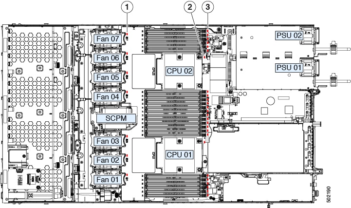
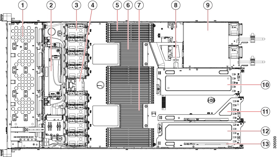
Eight hot-swappable fan modules for front-to-rear cooling.

PCIe I/O

Horizontal PCIe expansion slots are supported by PCIe riser assemblies. The server supports either of the following configurations:

  • One half-height riser card in PCIe Riser 1

  • Three half-height riser cards in PCIe Riser 1, 2, 3

  • Two full-height riser cards

InfiniBand

The PCIe bus slots in this server support the InfiniBand architecture.

Expansion Slots

Three half-height riser slots

  • Riser 1 (controlled by CPU 1): One x16 PCIe Gen4 Slot, (Cisco VIC), half-height, 3/4 length

  • Riser 2 (controlled by CPU 1): One x16 PCIe Gen4 Slot, electrical x8, half-height, 3/4 length

  • Riser 3 (controlled by CPU 1): One x16 PCIe Gen4 Slot, (Cisco VIC), half-height, 3/4 length

Two full-height riser slots

  • Riser 1 (controlled by CPU 1): One x16 PCIe Gen4 Slot, (Cisco VIC), full-height, 3/4 length

  • Riser 3 (controlled by CPU 1): One x16 PCIe Gen4 Slot, (Cisco VIC), full-height, 3/4 length

Interfaces

Rear panel:

  • One 1Gbase-T RJ-45 management port

  • One RS-232 serial port (RJ45 connector)

  • One DB15 VGA connector

  • Two USB 3.0 port connectors

  • One flexible modular LAN on motherboard (mLOM) slot that can accommodate various interface cards

Front panel:

  • One KVM console connector (supplies two USB 2.0 connectors, one

  • VGA DB15 video connector, and one serial port (RS232) RJ45 connector)

Storage, front-panel

Cisco APIC M4 and L4 (APIC-SERVER-M4 and APIC-SERVER-L4)—The server is orderable in two different versions, each with a different front panel/drive-backplane configuration.

Storage, internal

The server has these internal storage options:

  • One USB port on the motherboard.

  • Mini-storage module socket, optionally with either:

    • SD card module. Supports up to two SD cards.

    • M.2 SSD module. Supports either two SATA M.2 SSDs or two NVMe M.2 SSDs.

  • One micro-SD card socket on PCIe riser 1.

  • Mixing different capacity SATA M.2 SSDs is not supported.

  • It also supports USB3.0 TypeA connector.

Integrated Management Processor

Baseboard Management Controller (BMC) running Cisco Integrated Management Controller (CIMC) firmware.

Depending on your CIMC settings, the CIMC can be accessed through the 1GE dedicated management port, the 1GE/10GE LOM ports, or a Cisco virtual interface card (VIC).

CIMC manages certain components within the server, such as the Cisco 12G SAS HBA.

Storage Controllers

The Cisco 12G SAS RAID controller or Cisco 12G SAS HBA plugs into a dedicated slot. Only one of these at a time can be used at a time.

  • Cisco 12G SAS RAID controller

    • RAID support (RAID 0, 1, 5, 6, 10, 50, 60, SRAID0, and JBOD mode)

    • Supports up to 10 internal SAS/SATA drives

    • Plugs into drive backplane

  • Cisco 12G SAS HBA

    • No RAID support

      JBOD/Pass-through Mode support

      Supports up to 10 SAS/SATA internal drives

      Plugs into drive backplane

Modular LAN over Motherboard (mLOM) slot

The dedicated mLOM slot on the motherboard can flexibly accommodate the following cards:

  • Cisco Virtual Interface Cards (VICs)

RAID backup

The server has a mounting bracket near the cooling fans for the supercap unit that is used with the Cisco modular RAID controller card.

Integrated video

Integrated VGA video.

Intersight

Intersight provides server management capabilities