Cisco APIC REST API Configuration Guide, Release 3.x and Earlier
Bias-Free Language
The documentation set for this product strives to use bias-free language. For the purposes of this documentation set, bias-free is defined as language that does not imply discrimination based on age, disability, gender, racial identity, ethnic identity, sexual orientation, socioeconomic status, and intersectionality. Exceptions may be present in the documentation due to language that is hardcoded in the user interfaces of the product software, language used based on RFP documentation, or language that is used by a referenced third-party product. Learn more about how Cisco is using Inclusive Language.
A fabric
administrator creates domain policies that configure ports, protocols, VLAN
pools, and encapsulation. These policies can be used exclusively by a single
tenant, or shared. Once a fabric administrator configures domains in the ACI
fabric, tenant administrators can associate tenant endpoint groups (EPGs) to
domains.
The following networking domain profiles can be configured:
VMM domain
profiles (vmmDomP) are required for virtual machine hypervisor
integration.
Physical domain
profiles (physDomP) are typically used for bare metal server
attachment and management access.
Bridged outside
network domain profiles (l2extDomP) are typically used to connect a bridged
external network trunk switch to a leaf switch in the ACI fabric.
Routed outside
network domain profiles (l3extDomP) are used to connect a router to a leaf
switch in the ACI fabric.
Fibre Channel domain profiles (fcDomP) are used to connect Fibre Channel VLANs and VSANs.
A domain is configured
to be associated with a VLAN pool. EPGs are then configured to use the VLANs
associated with a domain.
Note
EPG port and VLAN
configurations must match those specified in the domain infrastructure
configuration with which the EPG associates. If not, the APIC will raise a
fault. When such a fault occurs, verify that the domain infrastructure
configuration matches the EPG port and VLAN configurations.
Configuring a Physical Domain Using the REST API
A physical domain acts as the link between the VLAN pool and the Access Entity Profile (AEP). The domain also ties the fabric
configuration to the tenant configuration, as the tenant administrator is the one who associates domains to EPGs, while the
domains are created under the fabric tab. When configuring in this order, only the profile name and the VLAN pool are configured.
Procedure
Configure a physical domain by sending a post with XML such as the following example:
In this example,
configuring newly-connected bare metal servers first requires creation of a
physical domain and then association of the domain to a VLAN pool. As mentioned
in the previous section, VLAN pools define a range of VLAN IDs that will be
used by the EPGs.
The servers are
connected to two different leaf nodes in the fabric. Each server will be
tagging using 802.1Q or VXLAN encapsulation. The range of VLANs used in the
configuration example is 100-199. As depicted in the following figure, the ACI
fabric can also act as a gateway between disparate encapsulation types such as
untagged traffic, 802.1Q VLAN tags, VXLAN VNIDs, and NVGRE tags. The leaf
switches normalize the traffic by stripping off tags and reapplying the
required tags on fabric egress. In ACI, it is important to understand that the
definition of VLANs as they pertain to the leaf switch ports is utilized only
for identification purposes. When a packet arrives ingress to a leaf switch in
the fabric, ACI has to know beforehand how to classify packets into the
different EPGs, using identifiers like VLANs, VXLAN, NVGRE, physical port IDs,
virtual port IDs.
Figure 1. Encapsulation
normalization
Creating a VLAN Pool
Using the REST API
The following example REST request creates a VLAN pool:
Using Cisco Application Policy Infrastructure
Controller (APIC), you can map double-tagged VLAN traffic ingressing on a regular interface, PC, or vPC to an EPG. When this feature is enabled,
when double-tagged traffic enters the network for an EPG, both tags are processed individually in the fabric and restored
to double-tags when egressing the Cisco Application Centric
Infrastructure (ACI) switch. Ingressing single-tagged and untagged traffic is dropped.
The following guidelines and limitations apply:
This feature is only supported on Cisco Nexus 9300-FX platform switches.
Both the outer and inner tag must be of EtherType 0x8100.
MAC learning and routing are based on the EPG port, sclass, and VRF instance, not on the access encapsulations.
QoS priority settings are supported, derived from the outer tag on ingress, and rewritten to both tags on egress.
EPGs can simultaneously be associated with other interfaces on a leaf switch, that are configured for single-tagged VLANs.
Service graphs are supported for provider and consumer EPGs that are mapped to Q-in-Q encapsulated interfaces. You can insert
service graphs, as long as the ingress and egress traffic on the service nodes is in single-tagged encapsulated frames.
When vPC ports are enabled for Q-in-Q encapsulation mode, VLAN consistency checks are not performed.
The following features and options are not supported with this feature:
Per-port VLAN feature
FEX connections
Mixed mode
For example, an interface in Q-in-Q encapsulation mode can have a static path binding to an EPG with double-tagged encapsulation
only, not with regular VLAN encapsulation.
STP and the "Flood in Encapsulation" option
Untagged and 802.1p mode
Multi-pod and Multi-Site
Legacy bridge domain
L2Out and L3Out connections
VMM integration
Changing a port mode from routed to Q-in-Q encapsulation mode
Per-VLAN mis-cabling protocol on ports in Q-in-Q encapsulation mode
Mapping EPGs to Q-in-Q Encapsulation Enabled Interfaces Using the REST API
Before you begin
Create the tenant, application profile, and application EPG that will be mapped with an interface configured for Q-in-Q mode.
Procedure
Enable an interface for Q-in-Q encapsulation and associate the interface with an EPG, with XML such as the following example:
The ACI fabric
provides multiple attachment points that connect through leaf ports to various
external entities such as bare metal servers, virtual machine hypervisors,
Layer 2 switches (for example, the Cisco UCS fabric interconnect), or Layer 3
routers (for example Cisco Nexus 7000 Series switches). These attachment points
can be physical ports, FEX ports, port channels, or a virtual port channel
(vPC) on leaf switches.
Note
When creating a VPC domain between two leaf switches, both switches must be in the same switch generation, one of the following:
Generation 1 - Cisco Nexus N9K switches without “EX” or "FX" on the end of the switch name; for example, N9K-9312TX
Generation 2 – Cisco Nexus N9K switches with “EX” or "FX" on the end of the switch model name; for example, N9K-93108TC-EX
Switches such as these two are not compatible VPC peers. Instead, use switches of the same generation.
An Attachable Entity Profile (AEP) represents a group of external entities with similar infrastructure policy requirements.
The infrastructure policies consist of physical interface policies that configure various protocol options, such as Cisco
Discovery Protocol (CDP), Link Layer Discovery Protocol (LLDP), or Link Aggregation Control Protocol (LACP).
An AEP is required to
deploy VLAN pools on leaf switches. Encapsulation blocks (and associated VLANs)
are reusable across leaf switches. An AEP implicitly provides the scope of the
VLAN pool to the physical infrastructure.
The following AEP requirements and dependencies must be accounted for in various configuration scenarios, including network
connectivity, VMM domains, and multipod configuration:
The AEP defines
the range of allowed VLANS but it does not provision them. No traffic flows
unless an EPG is deployed on the port. Without defining a VLAN pool in an AEP,
a VLAN is not enabled on the leaf port even if an EPG is provisioned.
A particular VLAN
is provisioned or enabled on the leaf port that is based on EPG events either
statically binding on a leaf port or based on VM events from external
controllers such as VMware vCenter or Microsoft Azure Service Center Virtual
Machine Manager (SCVMM).
Attached entity profiles can be associated directly with application EPGs, which deploy the associated application EPGs to
all those ports associated with the attached entity profile. The AEP has a configurable generic function (infraGeneric), which
contains a relation to an EPG (infraRsFuncToEpg) that is deployed on all interfaces that are part of the selectors that are
associated with the attachable entity profile.
A virtual machine
manager (VMM) domain automatically derives physical interface policies from the
interface policy groups of an AEP.
An override policy at
the AEP can be used to specify a different physical interface policy for a VMM
domain. This policy is useful in scenarios where a VM controller is connected
to the leaf switch through an intermediate Layer 2 node, and a different policy
is desired at the leaf switch and VM controller physical ports. For example,
you can configure LACP between a leaf switch and a Layer 2 node. At the same
time, you can disable LACP between the VM controller and the Layer 2 switch by
disabling LACP under the AEP override policy.
Creating an
Attachable Access Entity Profile Using the REST API
The following example
REST request creates an attachable access entity profile (AEP):
Configuring a Single Port Channel Applied to Multiple Switches
This example creates a port channel on leaf switch 17, another port channel on leaf switch 18, and a third one on leaf switch
20. On each leaf switch, the same interfaces will be part of the port channel (interfaces 1/10 to 1/15 and 1/20 to 1/25).
All these port channels will have the same configuration.
Before you begin
The ACI fabric is installed, APIC controllers are online, and the APIC cluster is formed and healthy.
An APIC fabric administrator account is available that will enable creating the necessary fabric infrastructure configurations.
The target leaf switch and protocol(s) are configured and available.
Procedure
To create the port channel, send a post with XML such as the following:
Configuring a Single Virtual Port Channel Across Two Switches Using the REST API
The two steps for creating a virtual port channel across two switches are as follows:
Create a fabricExplicitGEp: this policy specifies the leaf switch that pairs to form the virtual port channel.
Use the infra selector to specify the interface configuration.
The APIC performs several validations of the fabricExplicitGEp and faults are raised when any of these validations fail. A leaf can be paired with only one other leaf. The APIC rejects any configuration that breaks this rule. When creating a fabricExplicitGEp, an administrator must provide the IDs of both of the leaf switches to be paired. The APIC rejects any configuration which breaks this rule. Both switches must be up when fabricExplicitGEp is created. If one switch is not up, the APIC accepts the configuration but raises a fault. Both switches must be leaf switches. If one or both switch IDs corresponds
to a spine, the APIC accepts the configuration but raises a fault.
Before you begin
The ACI fabric is installed, APIC controllers are online, and the APIC cluster is formed and healthy.
An APIC fabric administrator account is available that will enable creating the necessary fabric infrastructure configurations.
The target leaf switch and protocol(s) are configured and available.
Procedure
To create the fabricExplicitGEp policy and use the intra selector to specify the interface, send a post with XML such as the following example:
Configuring Two Port Channels Applied to Multiple Switches Using the REST API
This example creates two port channels (PCs) on leaf switch 17, another port channel on leaf switch 18, and a third one on
leaf switch 20. On each leaf switch, the same interfaces will be part of the PC (interface 1/10 to 1/15 for port channel 1
and 1/20 to 1/25 for port channel 2). The policy uses two switch blocks because each a switch block can contain only one group
of consecutive switch IDs. All these PCs will have the same configuration.
Note
Even though the PC configurations are the same, this example uses two different interface policy groups. Each Interface Policy
Group represents a PC on a switch. All interfaces associated with a given interface policy group are part of the same PCs.
Before you begin
The ACI fabric is installed, APIC controllers are online, and the APIC cluster is formed and healthy.
An APIC fabric administrator account is available that will enable creating the necessary fabric infrastructure configurations.
The target leaf switch and protocol(s) are configured and available.
Procedure
To create the two PCs, send a post with XML such as the following:
Configuring a Virtual Port Channel on Selected Port Blocks of Two Switches Using the REST API
This policy creates a single virtual port channel (vPC) on leaf switches 18 and 25, using interfaces 1/10 to 1/15 on leaf
18, and interfaces 1/20 to 1/25 on leaf 25.
Before you begin
The ACI fabric is installed, APIC controllers are online, and the APIC cluster is formed and healthy.
An APIC fabric administrator account is available that will enable creating the necessary fabric infrastructure configurations.
The target leaf switch and protocol(s) are configured and available.
Note
When creating a vPC domain between two leaf switches, both switches must be in the same switch generation, one of the following:
Generation 1 - Cisco Nexus N9K switches without “EX” on the end of the switch name; for example, N9K-9312TX
Generation 2 – Cisco Nexus N9K switches with “EX” on the end of the switch model name; for example, N9K-93108TC-EX
Switches such as these two are not compatible vPC peers. Instead, use switches of the same generation.
Procedure
To create the vPC send a post with XML such as the following example:
Reflective relay is a switching option beginning with Cisco APIC Release 2.3(1). Reflective relay—the tagless approach of
IEEE standard 802.1Qbg—forwards all traffic to an external switch, which then applies policy and sends the traffic back to
the destination or target VM on the server as needed. There is no local switching. For broadcast or multicast traffic, reflective
relay provides packet replication to each VM locally on the server.
One benefit of reflective relay is that it leverages the external switch for switching features and management capabilities,
freeing server resources to support the VMs. Reflective relay also allows policies that you configure on the Cisco APIC to
apply to traffic between the VMs on the same server.
In the Cisco ACI, you can enable reflective relay, which allows traffic to turn back out of the same port it came in on. You
can enable reflective relay on individual ports, port channels, or virtual port channels as a Layer 2 interface policy using
the APIC GUI, NX-OS CLI, or REST API. It is disabled by default.
The term Virtual Ethernet Port Aggregator (VEPA) is also used to describe 802.1Qbg functionality.
Reflective Relay Support
Reflective relay supports the following:
IEEE standard 802.1Qbg tagless approach, known as reflective relay.
Cisco APIC Release 2.3(1) release does not support the IEE standard 802.1Qbg S-tagged approach with multichannel technology.
Physical domains.
Virtual domains are not supported.
Physical ports, port channels (PCs), and virtual port channels (vPCs).
Cisco Fabric Extender (FEX) and blade servers are not supported. If reflective relay is enabled on an unsupported interface,
a fault is raised, and the last valid configuration is retained. Disabling reflective relay on the port clears the fault.
Cisco Nexus 9000 series switches with EX or FX at the end of their model name.
Enabling Reflective Relay Using the REST API
Reflective relay is disabled by default; however, you can enable it on a port, port channel, or virtual port channel as a
Layer 2 interface policy on the switch.
Before you begin
This procedure assumes that you have set up the Cisco Application Centric Infrastructure (ACI) fabric and installed the physical
switches.
Procedure
Step 1
Configure a Layer 2 Interface policy with reflective relay enabled.
Example:
<l2IfPol name=“VepaL2IfPol” vepa=“enabled" />
Step 2
Apply the Layer 2 interface policy to a leaf access port policy group.
When configuring interfaces in a Cisco Application Centric
Infrastructure (ACI) fabric, follow these guidelines.
Half duplex at
100Mbps speed is not supported
In a Cisco ACI leaf switch that supports 100Mbps speed, the 100Mbps speed is supported only if the link is in full duplex mode and if autonegotiation
is configured the same on both the local and remote peer. The Cisco ACI leaf switch and the remote link should both be configured in full duplex mode with autonegotiation disabled on both devices
or enabled on both devices.
Connecting an
SFP module requires a link speed policy
When you connect an SFP module to a new card, you must create a link speed policy for the module to communicate with the card.
Follow these steps to create a link speed policy.
Create an interface policy to specify the link speed, as in this example:
<fabricHIfPol name="mySpeedPol" speed="1G"/>
Reference the link speed policy within an interface policy group, as in this example:
MAC pinning is used for pinning VM traffic in a round-robin fashion to each uplink based on the MAC address of the VM. In
a normal virtual port channel (vPC), a hash algorithm uses the source and destination MAC address to determine which uplink
will carry a packet. In a vPC with MAC pinning, VM1 might be pinned to the first uplink, VM2 pinned to the second uplink,
and so on.
MAC pinning is the recommended option for channeling when connecting to upstream switches that do not support Multichassis
EtherChannel (MEC).
Consider these guidelines and restrictions when configuring MAC pinning:
When a Cisco Application Virtual Switch or Cisco ACI Virtual Edge is deployed behind a vPC with MAC pinning and a host is connected to two leaf switches using that same vPC, reloading one
of the two leaf switches can result in a few minutes of traffic disruption.
In the API, MAC pinning is selected in the LACP policy by setting lacp:LagPol:mode to mac-pin. When the policy is applied
to a vPC, the vPC status as shown in pc:AggrIf:pcMode and in pc:AggrIf:operChannelMode is displayed as active, not as mac-pin.
Changing Interface Speed
This task creates a policy that configures the speed for a set of interfaces.
Procedure
To set the speed for a set of interfaces, send a post with XML such as the following example:
Observe the following guidelines when deploying a FEX:
Assuming that no leaf switch front panel ports are configured to deploy and EPG and VLANs, a maximum of 10,000 port EPGs are
supported for being deployed using a FEX.
For each FEX port or vPC that includes FEX ports as members, a maximum of 20 EPGs per VLAN are supported.
A vPC with FEX interfaces ignores the minimum and maximum number of links configured in its port-channel policy. The vPC remains
up even if the number of links is less than the minimum or greater than the maximum.
Configuring an FEX VPC Policy Using the REST API
This task creates a FEX virtual port channel (VPC) policy.
Before you begin
The ACI fabric is installed, APIC controllers are online, and the APIC cluster is formed and healthy.
An APIC fabric administrator account is available that will enable creating the necessary fabric infrastructure configurations.
The target leaf switch, interfaces, and protocol(s) are configured and available.
The FEXes are configured, powered on, and connected to the target leaf interfaces
Note
When creating a VPC domain between two leaf switches, both switches must be in the same switch generation, one of the following:
Generation 1 - Cisco Nexus N9K switches without “EX” on the end of the switch name; for example, N9K-9312TX
Generation 2 – Cisco Nexus N9K switches with “EX” on the end of the switch model name; for example, N9K-93108TC-EX
Switches such as these two are not compatible VPC peers. Instead, use switches of the same generation.
Procedure
To create the policy linking the FEX through a VPC to two switches, send a post with XML such as the following example:
Supporting Fibre
Channel over Ethernet Traffic on the ACI Fabric
Cisco ACI enables you to configure and manage support for Fibre Channel over Ethernet (FCoE) traffic on the ACI fabric.
FCoE is a protocol that encapsulates Fibre Channel (FC) packets within Ethernet packets, thus enabling storage traffic to
move seamlessly between a Fibre Channel SAN and an Ethernet network.
A typical implementation of FCoE protocol support on the ACI fabric enables hosts located on the Ethernet-based ACI fabric
to communicate with SAN storage devices located on an FC network. The hosts are connecting through virtual F ports deployed
on an ACI leaf switch. The SAN storage devices and FC network are connected through a Fibre Channel Forwarding (FCF) bridge
to the ACI fabric through a virtual NP port, deployed on the same ACI leaf switch as is the virtual F port. Virtual NP ports
and virtual F ports are also referred to generically as virtual Fibre Channel (vFC) ports.
Note
In the FCoE topology, the role of the ACI leaf switch is to provide a path for FCoE traffic between the locally connected
SAN hosts and a locally connected FCF device. The leaf switch does not perform local switching between SAN hosts, and the
FCoE traffic is not forwarded to a spine switch.
Topology Supporting FCoE Traffic Through ACI
The topology of a typical configuration supporting FCoE traffic over the ACI fabric consists of the following components:
Figure 2. ACI Topology Supporting FCoE Traffic
One or more ACI leaf switches configured through FC SAN policies to function as an NPV backbone.
Selected interfaces on the NPV-configured leaf switches configured to function as virtual F ports, which accommodate FCoE
traffic to and from hosts running SAN management or SAN-consuming applications.
Selected interfaces on the NPV-configured leaf switches configured to function as virtual NP ports, which accommodate FCoE
traffic to and from a Fibre Channel Forwarding (FCF) bridge.
The FCF bridge receives FC traffic from fibre channel links typically connecting SAN storage devices and encapsulates the
FC packets into FCoE frames for transmission over the ACI fabric to the SAN management or SAN Data-consuming hosts. It receives
FCoE traffic and repackages it back to FC for transmission over the fibre channel network.
Note
In the above ACI topology, FCoE traffic support requires direct connections between the hosts and virtual F ports and direct
connections between the FCF device and the virtual NP port.
APIC servers enable an operator to configure and monitor the FCoE traffic through the APIC GUI, the APIC NX-OS style CLI,
or through application calls to the APIC REST API.
Topology
Supporting FCoE Initialization
In order for FCoE traffic flow to take place as described, you must also set up separate VLAN connectivity over which SAN
Hosts broadcast FCoE Initialization protocol (FIP) packets to discover the interfaces enabled as F ports.
vFC
Interface Configuration Rules
Whether you set up the vFC network and EPG deployment through the APIC GUI, NX-OS style CLI, or the REST API, the following
general rules apply across platforms:
F port mode
is the default mode for vFC ports. NP port mode must be specifically configured
in the Interface policies.
The load
balancing default mode is for leaf-switch or interface level vFC configuration
is src-dst-ox-id.
One VSAN
assignment per bridge domain is supported.
The
allocation mode for VSAN pools and VLAN pools must always be static.
vFC ports require association with a VSAN domain (also called Fibre Channel domain) that contains VSANs mapped to VLANs.
Configuring FCoE
Connectivity Using the REST API
You can configure FCoE-enabled interfaces and EPGs accessing those interfaces using the FCoE protocol with the REST API.
Procedure
Step 1
To create a VSAN pool, send a post with XML such as the following example.
The example creates VSAN pool vsanPool1 and specifies the range of VSANs to be included.
To create the tenant, application profile, EPG and associate the FCoE bridge domain with the EPG, send a post with XML such
as the following example.
The example creates a bridge domain bd1 under a target tenant configured to support FCoE and an application EPG epg1. It associates the EPG with VSAN domain vsanDom1 and a Fibre Channel path (to interface 1/39 on leaf switch 101. It deletes a Fibre channel path to interface 1/40 by assigning the <fvRsFcPathAtt> object with "deleted" status. Each interface is associated with a VSAN.
Note
Two other possible alternative vFC deployments are also displayed. One sample deploys vFC on a port channel. The other sample
deploys vFC on a virtual port channel.
Example:
https://apic-ip-address/api/mo/uni/tn-tenant1.xml

<fvTenant
name="tenant1">
  <fvCtx name="vrf1"/>

  <!-- bridge domain -->
  <fvBD name="bd1" type="fc" >
    <fvRsCtx tnFvCtxName="vrf1" />
  </fvBD>

  <fvAp name="app1">
    <fvAEPg name="epg1">
      <fvRsBd tnFvBDName="bd1" />
      <fvRsDomAtt tDn="uni/fc-vsanDom1" />
      <fvRsFcPathAtt tDn="topology/pod-1/paths-101/pathep-[eth1/39]"
       vsan="vsan-11" vsanMode="native"/>
      <fvRsFcPathAtt tDn="topology/pod-1/paths-101/pathep-[eth1/40]"
       vsan="vsan-10" vsanMode="regular" status="deleted"/>
    </fvAEPg>

<!-- Sample deployment of vFC on a port channel -->

      <fvRsFcPathAtt vsanMode="native" vsan="vsan-10"
       tDN="topology/pod-1/paths 101/pathep-pc01"/>

<!-- Sample deployment of vFC on a virtual port channel -->

      <fvRsFcPathAtt vsanMode="native" vsan="vsan-10"
       tDn="topology/pod-1/paths-101/pathep-vpc01"/>
      <fvRsFcPathAtt vsanMode="native" vsan="vsan-10"
       tDn="topology/pod-1/paths-102/pathep-vpc01"/>

  </fvAp>
</fvTenant>
Step 6
To create a port policy group and an AEP, send a post with XML such as the following example.
The example executes the following requests:
Creates a policy group portgrp1 that includes an FC interface policy fcIfPol1, a priority flow control policy pfcIfPol1 and a slow-drain policy sdIfPol1.
Creates an attached entity profile (AEP) AttEntP1 that associates the ports in VSAN domain vsanDom1 with the settings to be specified for fcIfPol1, pfcIfPol1, and sdIfPol1.
Undeploying FCoE
Connectivity through the REST API or SDK
To undeploy FCoE connectivity through the APIC REST API or SDK , delete the following objects associated with the deployment:
Object
Description
<fvRsFcPathAtt> (Fibre Channel Path)
The Fibre Channel path specifies the vFC path to the actual
interface. Deleting each object of this type removes the deployment from that
object's associated interfaces.
<fcVsanAttrpP> (VSAN/VLAN map)
The VSAN/VLAN map maps the VSANs to their associated VLANs
deleting this object removes the association between the VSANs that support
FCoE connectivity and their underlying VSANs.
<fvnsVsanInstP> (VSAN pool)
The VSAN pool specifies the set of VSANs available to support FCoE connectivity. Deleting this pool removes those VSANs.
<fvnsVlanIsntP> ((VLAN pool)
The VLAN pool specifies the set of VLANs available for VSAN
mapping. Deleting the associated VLAN pool cleans up after an FCoE
undeployment, removing the underlying VLAN entities over which the VSAN
entities ran.
<fcDomP> (VSAN or Fibre Channel domain)
The Fibre Channel domain includes all the VSANs and their
mappings. Deleting this object undeploys vFC from all interfaces associated
with this domain.
<fvAEPg> (application EPG)
The application EPG associated with the FCoE connectivity.
If the purpose of the application EPGs was only to support FCoE-related
activity, you might consider deleting this object.
<fvAp> (application profile)
The application profile associated with the FCoE
connectivity. If the purpose of the application profile was only to support
FCoE-related activity, you might consider deleting this object.
<fvTenant> (tenant)
The tenant associated with the FCoE connectivity. If the
purpose of the tenant was only to support FCoE-related activity, you might
consider deleting this object.
Note
If during clean up you delete the Ethernet configuration object
(infraHPortS) for a vFC port, the default vFC properties remain associated with
that interface. For example it the interface configuration for vFC NP port 1/20
is deleted, that port remains a vFC port but with default F port setting rather
than non-default NP port setting applied.
The following steps undeploy FCoE-enabled interfaces and EPGs accessing those interfaces using the FCoE protocol.
Procedure
Step 1
To delete the associated Fibre Channel path objects, send a post with XML such as the following example.
The example deletes all instances of the Fibre Channel path object <fvRsFcPathAtt>.
Note
Deleting the Fibre Channel paths undeploys the vFC from the ports/VSANs that used them.
Example:
https://apic-ip-address/api/mo/uni/tn-tenant1.xml

<fvTenant
name="tenant1">
  <fvCtx name="vrf1"/>

  <!-- bridge domain -->
  <fvBD name="bd1" type="fc" >
    <fvRsCtx tnFvCtxName="vrf1" />
  </fvBD>

  <fvAp name="app1">
    <fvAEPg name="epg1">
      <fvRsBd tnFvBDName="bd1" />
      <fvRsDomAtt tDn="uni/fc-vsanDom1" />
      <fvRsFcPathAtt tDn="topology/pod-1/paths-101/pathep-[eth1/39]"
       vsan="vsan-11" vsanMode="native" status="deleted"/>
      <fvRsFcPathAtt tDn="topology/pod-1/paths-101/pathep-[eth1/40]"
       vsan="vsan-10" vsanMode="regular" status="deleted"/>
    </fvAEPg>

<!-- Sample undeployment of vFC on a port channel -->

      <fvRsFcPathAtt vsanMode="native" vsan="vsan-10"
       tDN="topology/pod-1/paths 101/pathep-pc01" status="deleted"/>

<!-- Sample undeployment of vFC on a virtual port channel -->

      <fvRsFcPathAtt vsanMode="native" vsan="vsan-10"
       tDn="topology/pod-1/paths-101/pathep-vpc01" status="deleted"/>
      <fvRsFcPathAtt vsanMode="native" vsan="vsan-10"
       tDn="topology/pod-1/paths-102/pathep-vpc01" status="deleted"/>

  </fvAp>
</fvTenant>
Step 2
To delete the associated VSAN/VLAN map, send a post such as the following example.
The example deletes the VSAN/VLAN map vsanattri1 and its associated <fcVsanAttrpP> object.
Optional: If appropriate, you can delete the associated application EPG, the associated application profile, or the associated tenant.
Example:
In the following sample, the associated application EPG epg1 and its associated <fvAEPg> object is deleted.
https://apic-ip-address/api/mo/uni/tn-tenant1.xml

<fvTenant
name="tenant1"/>
  <fvCtx name="vrf1"/>

  <!-- bridge domain -->
  <fvBD name="bd1" type="fc" >
    <fvRsCtx tnFvCtxName="vrf1" />
  </fvBD>

  <fvAp name="app1">
    <fvAEPg name="epg1" status= "deleted">
      <fvRsBd tnFvBDName="bd1" />
      <fvRsDomAtt tDn="uni/fc-vsanDom1" />
      <fvRsFcPathAtt tDn="topology/pod-1/paths-101/pathep-[eth1/39]"
       vsan="vsan-11" vsanMode="native" status="deleted"/>
      <fvRsFcPathAtt tDn="topology/pod-1/paths-101/pathep-[eth1/40]"
       vsan="vsan-10" vsanMode="regular" status="deleted"/>
    </fvAEPg>

<!-- Sample undeployment of vFC on a port channel -->

      <fvRsFcPathAtt vsanMode="native" vsan="vsan-10"
       tDN="topology/pod-1/paths 101/pathep-pc01" status="deleted"/>

<!-- Sample undeployment of vFC on a virtual port channel -->

      <fvRsFcPathAtt vsanMode="native" vsan="vsan-10"
       tDn="topology/pod-1/paths-101/pathep-vpc01" status="deleted"/>
      <fvRsFcPathAtt vsanMode="native" vsan="vsan-10"
       tDn="topology/pod-1/paths-102/pathep-vpc01" status="deleted"/>

  </fvAp>
</fvTenant>
Example:
In the following example, the associated application profile app1 and its associated <fvAp> object is deleted.
https://apic-ip-address/api/mo/uni/tn-tenant1.xml

<fvTenant
name="tenant1">
  <fvCtx name="vrf1"/>

  <!-- bridge domain -->
  <fvBD name="bd1" type="fc">
    <fvRsCtx tnFvCtxName="vrf1" />
  </fvBD>

  <fvAp name="app1" status="deleted">
    <fvAEPg name="epg1" status= "deleted">
      <fvRsBd tnFvBDName="bd1" />
      <fvRsDomAtt tDn="uni/fc-vsanDom1" />
      <fvRsFcPathAtt tDn="topology/pod-1/paths-101/pathep-[eth1/39]"
       vsan="vsan-11" vsanMode="native" status="deleted"/>
      <fvRsFcPathAtt tDn="topology/pod-1/paths-101/pathep-[eth1/40]"
       vsan="vsan-10" vsanMode="regular" status="deleted"/>
    </fvAEPg>

<!-- Sample undeployment of vFC on a port channel -->

      <fvRsFcPathAtt vsanMode="native" vsan="vsan-10"
       tDN="topology/pod-1/paths 101/pathep-pc01" status="deleted"/>

<!-- Sample undeployment of vFC on a virtual port channel -->

      <fvRsFcPathAtt vsanMode="native" vsan="vsan-10"
       tDn="topology/pod-1/paths-101/pathep-vpc01" status="deleted"/>
      <fvRsFcPathAtt vsanMode="native" vsan="vsan-10"
       tDn="topology/pod-1/paths-102/pathep-vpc01" status="deleted"/>

  </fvAp>
</fvTenant>
Example:
In the following example, the entire tenant tenant1 and its associated <fvTenant> object is deleted.
https://apic-ip-address/api/mo/uni/tn-tenant1.xml

<fvTenant
name="tenant1" status="deleted">
  <fvCtx name="vrf1"/>

  <!-- bridge domain -->
  <fvBD name="bd1" type="fc" status="deleted">
    <fvRsCtx tnFvCtxName="vrf1" />
  </fvBD>

  <fvAp name="app1">
    <fvAEPg name="epg1" status= "deleted">
      <fvRsBd tnFvBDName="bd1" />
      <fvRsDomAtt tDn="uni/fc-vsanDom1" />
      <fvRsFcPathAtt tDn="topology/pod-1/paths-101/pathep-[eth1/39]"
       vsan="vsan-11" vsanMode="native" status="deleted"/>
      <fvRsFcPathAtt tDn="topology/pod-1/paths-101/pathep-[eth1/40]"
       vsan="vsan-10" vsanMode="regular" status="deleted"/>
    </fvAEPg>

<!-- Sample undeployment of vFC on a port channel -->

      <fvRsFcPathAtt vsanMode="native" vsan="vsan-10"
       tDN="topology/pod-1/paths 101/pathep-pc01" status="deleted"/>

<!-- Sample undeployment of vFC on a virtual port channel -->

      <fvRsFcPathAtt vsanMode="native" vsan="vsan-10"
       tDn="topology/pod-1/paths-101/pathep-vpc01" status="deleted"/>
      <fvRsFcPathAtt vsanMode="native" vsan="vsan-10"
       tDn="topology/pod-1/paths-102/pathep-vpc01" status="deleted"/>

  </fvAp>
</fvTenant>
802.1Q Tunnels
About ACI 802.1Q Tunnels
Figure 3. ACI 802.1Q Tunnels
With Cisco ACI and Cisco APIC Release 2.2(1x) and higher, you can configure 802.1Q tunnels on edge (tunnel) ports to enable point-to-multi-point tunneling
of Ethernet frames in the fabric, with Quality of Service (QoS) priority settings. A Dot1q Tunnel transports untagged, 802.1Q tagged, and 802.1ad double-tagged frames as-is across the fabric. Each tunnel carries the traffic
from a single customer and is associated with a single bridge domain. ACI front panel ports can be part of a Dot1q Tunnel. Layer 2 switching is done based on Destination MAC (DMAC) and regular MAC learning is done in the tunnel. Edge-port Dot1q Tunnels are supported on second-generation (and later) Cisco Nexus 9000 series switches with "EX" on the end of the switch model
name.
With Cisco ACI and Cisco APIC Release 2.3(x) and higher, you can also configure multiple 802.1Q tunnels on the same
core port to carry double-tagged traffic from multiple customers, each distinguished
with an access encapsulation configured for each 802.1Q tunnel. You can also disable MAC
Address Learning on 802.1Q tunnels. Both edge ports and core ports can belong to an
802.1Q tunnel with access encapsulation and disabled MAC Address Learning. Both edge
ports and core ports in Dot1q Tunnels are supported on
third-generation Cisco Nexus 9000 series switches with "FX" and "FX2" on the end of the
switch model name.
Terms used in this document may be different in the Cisco Nexus 9000 Series documents.
Table 1. 802.1Q Tunnel Terminology
ACI Documents
Cisco Nexus 9000 Series Documents
Edge Port
Tunnel Port
Core Port
Trunk Port
The following guidelines and restrictions apply:
Layer 2 tunneling of VTP, CDP, LACP, LLDP, and STP protocols is supported with the following restrictions:
Link Aggregation Control Protocol (LACP) tunneling functions as expected only with point-to-point tunnels using individual
leaf interfaces. It is not supported on port-channels (PCs) or virtual port-channels (vPCs).
CDP and LLDP tunneling with PCs or vPCs is not deterministic; it depends on the link it chooses as the traffic destination.
To use VTP for Layer 2 protocol tunneling, CDP must be enabled on the tunnel.
STP is not supported in an 802.1Q tunnel bridge domain when Layer 2 protocol tunneling is enabled and the bridge domain is
deployed on Dot1q Tunnel core ports.
ACI leaf switches react to STP TCN packets by flushing the end points in the tunnel bridge domain and flooding them in the
bridge domain.
CDP and LLDP tunneling with more than two interfaces flood packets on all interfaces.
With Cisco APIC Release 2.3(x) or higher, the destination MAC address of Layer 2 protocol packets tunneled from edge to core
ports is rewritten as 01-00-0c-cd-cd-d0 and the destination MAC address of Layer 2 protocol packets tunneled from core to
edge ports is rewritten with the standard default MAC address for the protocol.
If a PC or vPC is the only interface in a Dot1q Tunnel and it is deleted and reconfigured, remove the association of the PC/VPC to the Dot1q Tunnel and reconfigure it.
For 802.1Q tunnels deployed on switches that have EX in the product ID, Ethertype combinations of 0x8100+0x8100, 0x8100+0x88a8,
0x88a8+0x8100, and 0x88a8+0x88a8 for the first two VLAN tags are not supported.
If the tunnels are deployed on a combination of EX and FX or later switches, then this restriction still applies.
If the tunnels are deployed only on switches that have FX or later in the product ID, then this restriction does not apply.
For core ports, the Ethertypes for double-tagged frames must be 0x8100 followed by 0x8100.
You can include multiple edge ports and core ports (even across leaf switches) in a Dot1q Tunnel.
An edge port may only be part of one tunnel, but a core port can belong to multiple Dot1q tunnels.
With Cisco APIC Release 2.3(x) and higher, regular EPGs can be deployed on core ports that are used in 802.1Q tunnels.
L3Outs are not supported on interfaces enabled for Dot1q Tunnels.
FEX interfaces are not supported as members of a Dot1q Tunnel.
Interfaces configured as breakout ports do not support 802.1Q tunnels.
Interface-level statistics are supported for interfaces in Dot1q Tunnels, but statistics at the tunnel level are not supported.
Configuring 802.1Q Tunnels With Ports Using the REST API
Create a Dot1q Tunnel, using ports, and configure the interfaces for it with steps such as the following examples.
Before you begin
Configure the tenant that will use the Dot1q Tunnel.
Procedure
Step 1
Create a Dot1q Tunnel using the REST API with XML such as the following example.
The example configures the tunnel with the LLDP Layer 2 tunneling protocol, adds the access encapsulation VLAN, and disables
MAC learning in the tunnel.
Configure a Layer 2 Interface policy with static binding with XML such as the following example.
The example configures a Layer 2 interface policy for edge-switch ports. To configure a policy for core-switch ports, use
corePort instead of edgePort in the l2IfPol MO.
Configuring 802.1Q Tunnels With PCs Using the REST API
Create a Dot1q Tunnel, using PCs, and configure the interfaces for it with steps such as the following examples.
Before you begin
Configure the tenant that will use the Dot1q Tunnel.
Procedure
Step 1
Create a Dot1q Tunnel using the REST API with XML such as the following example.
The example configures the tunnel with the LLDP Layer 2 tunneling protocol, adds the access encapsulation VLAN, and disables
MAC learning in the tunnel.
Configure a Layer 2 Interface policy with static binding with XML such as the following example.
The example configures a Layer 2 interface policy for edge-switch ports. To configure a Layer 2 interface policy for core-switch
ports, use corePort instead of edgePort in the l2IfPol MO.
Example:
<l2IfPol name="testL2IfPol" qinq="edgePort"/>
Step 3
Apply the Layer 2 Interface policy to a PC Interface Policy Group with XML such as the following:
Configure a Layer 2 interface policy with static binding with XML such as the following example.
The example configures a Layer 2 interface policy for edge-switch ports. To configure a Layer 2 interface policy for core-switch
ports, use the qinq="corePort" port type.
Example:
<l2IfPol name="testL2IfPol" qinq="edgePort"/>
Step 3
Apply the Layer 2 Interface policy to a VPC Interface Policy Group with XML such as the following:
Breakout cables are suitable for very short links and offer a cost effective way to connect within racks and across adjacent
racks.
Breakout enables a 40 Gigabit (Gb) port to be split into four independent and logical 10Gb ports or a 100Gb port to be split
into four independent and logical 25Gb ports.
Before you configure breakout ports, connect a 40Gb port to four 10Gb ports or a 100Gb port to four 25Gb ports with one of
the following cables:
Cisco QSFP-4SFP10G
Cisco QSFP-4SFP25G
The 40Gb to 10Gb dynamic breakout feature is supported on the access facing ports of the following switches:
N9K-C9332PQ
N9K-C93180LC-EX
N9K-C9336C-FX
The 100Gb to 25Gb breakout feature is supported on the access facing ports of the following switches:
N9K-C93180LC-EX
N9K-C9336C-FX2
N9K-C93180YC-FX in the 3.2 and later releases
Observe the following guidelines and restrictions:
In general, breakout ports and port profiles (ports changed from uplink to downlink) are not supported on the same port.
However, from Cisco Application Policy Infrastructure
Controller (APIC) release 3.2, dynamic breakouts (both 100Gb and 40Gb) are supported on profiled QSFP ports on the N9K-C93180YC-FX switch.
Fast Link Failover policies are not supported on the same port with the dynamic breakout feature.
Breakout ports cannot be used for Cisco APIC connectivity.
Breakout subports can be used in the same way other port types in the policy model are used.
When a port is enabled for dynamic breakout, other policies (expect monitoring policies) on the parent port are no longer
valid.
When a port is enabled for dynamic breakout, other EPG deployments on the parent port are no longer valid.
A breakout sub-port can not be further broken out using a breakout policy group.
If the LACP transmit rate on port channels that have breakout sub-ports need to be changed, then all the port channels that
include breakout sub-ports need to use the same LACP transmit rate configuration. You can configure an override policy to
set the transmit rate as follows:
Configure/change the default port channel member policy to include Fast Transmit Rate (Fabric > Access Policies > Policies > Interface > Port Channel Member).
Configure all the PC/vPC interface policy groups to include the above default port channel member policy under the override
policy groups (Fabric > Access Policies > Interfaces > Leaf Interfaces > Policy Groups > PC/vPC Interface).
Configuring Dynamic Breakout Ports Using the REST API
Configure a Breakout Leaf Port with an Leaf Interface Profile, associate the profile with a switch, and configure the sub
ports with the following steps.
The ACI fabric is installed, APIC controllers are online, and the APIC cluster is formed and healthy.
An APIC fabric administrator account is available that will enable creating the necessary fabric infrastructure configurations.
The target leaf switches are registered in the ACI fabric and available.
The 40GE or 100GE leaf switch ports are connected with Cisco breakout cables to the downlink ports.
Procedure
Step 1
Configure a breakout policy group for the breakout port with JSON, such as the following example:
Example:
In this example, we create an interface profile 'brkout44' with the only port 44 underneath its port selector. The port selector
is pointed to a breakout policy group 'new-brkoutPol'.
Create a new switch profile and associate it with the port profile, previously created, with JSON such as the following example:
Example:
In this example, we create a new switch profile 'leaf1017' with switch 1017 as the only node. We associate this new switch
profile with the port profile 'brkout44' created above. After this, the port 44 on switch 1017 will have 4 sub ports.
This example configures subports 1/44/1, 1/44/2, 1/44/3, 1/44/4 on switch 1017, for instance, in the example below, we configure
interface 1/44/3. It also creates the infraSubPortBlk object instead of the infraPortBlk object.
Port Profiles to Change Uplinks to Downlinks and Downlinks to Uplinks
Configuring Port Profiles
Prior to Cisco Application Policy Infrastructure
Controller (APIC) release 3.1(1), conversion from uplink port to downlink port or downlink port to uplink port (in a port profile) was not
supported on Cisco Application Centric
Infrastructure (ACI) leaf switches. Starting with Cisco APIC release 3.1(1), uplink and downlink conversion is supported on Cisco Nexus 9000 series switches with names that end in EX
or FX, and later (for example, N9K-C9348GC-FXP). A FEX connected to converted downlinks is also supported.
This functionality is supported on the following Cisco switches:
N9K-C9348GC-FXP
N9K-C93180LC-EX and N9K-C93180YC-FX
N9K-C93108TC-EX and N9K-C93108TC-FX (only uplink to downlink conversion is supported)
N9K-C9336C-FX2 (only downlink to uplink conversion is supported)
Restrictions
Fast Link Failover policies and port profiles are not supported on the same port. If port profile is enabled, Fast Link Failover
cannot be enabled or vice versa.
The last 2 uplink ports of supported TOR switches cannot be converted to downlink ports (they are reserved for uplink connections.)
Up to Cisco APIC release 3.2, port profiles and breakout ports are not supported on the same ports.
With Cisco APIC release 3.2 and later, dynamic breakouts (both 100Gb and 40Gb) are supported on profiled QSFP ports on the N9K-C93180YC-FX
switch. Breakout and port profile are supported together for conversion of uplink to downlink on ports 49-52. Breakout (both
10g-4x or 25g-4x options) is supported on downlink profiled ports.
Reloading a switch after changing a switch's port profile configuration interrupts traffic through the data plane.
Guidelines
In converting uplinks to downlinks and downlinks to uplinks, consider the following guidelines.
Subject
Guideline
Decommissioning nodes with port profiles
If a decommissioned node has the Port Profile feature deployed on it, the port conversions are not removed even after decommissioning
the node. It is necessary to manually delete the configurations after decommission, for the ports to return to the default
state. To do this, log onto the switch, run the setup-clean-config.sh script, and wait for it to run. Then, enter the reload command.
FIPS
When you enable or disable Federal Information Processing Standards (FIPS) on a Cisco ACI fabric, you must reload each of the switches in the fabric for the change to take effect. The configured scale profile setting
is lost when you issue the first reload after changing the FIPS configuration. The switch remains operational, but it uses
the default scale profile. This issue does not happen on subsequent reloads if the FIPS configuration has not changed.
FIPS is supported on Cisco NX-OS release 13.1(1) or later.
If you must downgrade the firmware from a release that supports FIPS to a release that does not support FIPS, you must first
disable FIPS on the Cisco ACI fabric and reload all the switches in the fabric for the FIPS configuration change.
Maximum uplink port limit
When the maximum uplink port limit is reached and ports 25 and 27 are converted from uplink to downlink and back to uplink
on Cisco 93180LC-EX switches:
On Cisco 93180LC-EX Switches, ports 25 and 27 are the native uplink ports. Using the port profile, if you convert port 25
and 27 to downlink ports, ports 29, 30, 31, and 32 are still available as four native uplink ports. Because of the threshold
on the number of ports (which is maximum of 12 ports) that can be converted, you can convert 8 more downlink ports to uplink
ports. For example, ports 1, 3, 5, 7, 9, 13, 15, 17 are converted to uplink ports and ports 29, 30, 31 and 32 are the 4 native
uplink ports (the maximum uplink port limit on Cisco 93180LC-EX switches).
When the switch is in this state and if the port profile configuration is deleted on ports 25 and 27, ports 25 and 27 are
converted back to uplink ports, but there are already 12 uplink ports on the switch (as mentioned earlier). To accommodate
ports 25 and 27 as uplink ports, 2 random ports from the port range 1, 3, 5, 7, 9, 13, 15, 17 are denied the uplink conversion
and this situation cannot be controlled by the user.
Therefore, it is mandatory to clear all the faults before reloading the leaf node to avoid any unexpected behavior regarding
the port type. It should be noted that if a node is reloaded without clearing the port profile faults, especially when there
is a fault related to limit-exceed, the port might not be in an expected operational state.
Breakout Limitations
Switch
Releases
Limitations
N9K-C9332PQ
Cisco APIC 2.2 (1) and later
40Gb dynamic breakouts into 4X10Gb ports are supported.
Ports 13 and 14 do not support breakouts.
Port profiles and breakouts are not supported on the same port.
N9K-C93180LC-EX
Cisco APIC 3.1(1) and later
40Gb and 100Gb dynamic breakouts are supported on ports 1 through 24 on odd numbered ports.
When the top ports (odd ports) are broken out, then the bottom ports (even ports) are error disabled.
Port profiles and breakouts are not supported on the same port.
N9K-C9336C-FX2
Cisco APIC 3.1(2) and later
40Gb and 100Gb dynamic breakouts are supported on ports 1 through 30.
Port profiles and breakouts are not supported on the same port.
N9K-C93180YC-FX
Cisco APIC 3.2(1) and later
40Gb and 100Gb dynamic breakouts are supported on ports 49 though 52, when they are on profiled QSFP ports. To use them for
dynamic breakout, perform the following steps:
Convert ports 49-52 to front panel ports (downlinks).
Perform a port-profile reload, using one of the following methods:
In the Cisco APIC GUI, navigate to Fabric > Inventory > Pod > Leaf, right-click Chassis and choose Reload.
In the iBash CLI, enter the reload command.
Apply breakouts on the profiled ports 49-52.
Ports 53 and 54 do not support either port profiles or breakouts.
Port Profile Configuration Summary
The following table summarizes supported uplinks and downlinks for the switches that support port profile conversions from
Uplink to Downlink and Downlink to Uplink.
Switch Model
Default Links
Max Uplinks (Fabric Ports)
Max Downlinks (Server Ports)
Release Supported
N9K-C9348GC-FXP
48 x 100M/1G BASE-T downlinks
4 x 10/25-Gbps SFP28 downlinks
2 x 40/100-Gbps QSFP28 uplinks
48 x 100M/1G BASE-T downlinks
4 x 10/25-Gbps SFP28 uplinks
2 x 40/100-Gbps QSFP28 uplinks
Same as default port configuration
3.1(1i)
N9K-C93180LC-EX
24 x 40-Gbps QSFP28 downlinks(1-24)
2 x 40/100-Gbps QSFP28 uplinks(25, 27)
4 x 40/100-Gbps QSFP28 uplinks(29-32)
Or
12 x 100-Gbps QSFP28 downlinks(odd number from 1-24)
2 x 40/100-Gbps QSFP28 uplinks(25, 27)
4 x 40/100-Gbps QSFP28 uplinks(29-32)
18 x 40-Gbps QSFP28 downlinks (from 1-24)
6 x 40-Gbps QSFP28 uplinks(from 1-24)
2 x 40/100-Gbps QSFP28 uplinks(25, 27)
4 x 40/100-Gbps QSFP28 uplinks(29-32)
Or
6 x 100-Gbps QSFP28 downlinks(odd number from 1-24)
6 x 100-Gbps QSFP28 uplinks(odd number from 1-24)
2 x 40/100-Gbps QSFP28 uplinks(25, 27)
4 x 40/100-Gbps QSFP28 uplinks(29-32)
24 x 40-Gbps QSFP28 downlinks(1-24)
2 x 40/100-Gbps QSFP28 downlinks(25, 27)
4 x 40/100-Gbps QSFP28 uplinks(29-32)
Or
12 x 100-Gbps QSFP28 downlinks(odd number from 1-24)
2 x 40/100-Gbps QSFP28 downlinks (25, 27)
4 x 40/100-Gbps QSFP28 uplinks(29-32)
3.1(1i)
N9K-C93180YC-EX
N9K-C93180YC-FX
48 x 10/25-Gbps fiber downlinks
6 x 40/100-Gbps QSFP28 uplinks
Same as default port configuration
48 x 10/25-Gbps fiber downlinks
4 x 40/100-Gbps QSFP28 downlinks
2 x 40/100-Gbps QSFP28 uplinks
3.1(1i)
48 x 10/25-Gbps fiber uplinks
6 x 40/100-Gbps QSFP28 uplinks
4.0(1)
N9K-C93108TC-EX
N9K-C93108TC-FX
48 x 10GBASE-T downlinks
6 x 40/100-Gbps QSFP28 uplinks
Same as default port configuration
48 x 10/25-Gbps fiber downlinks
4 x 40/100-Gbps QSFP28 downlinks
2 x 40/100-Gbps QSFP28 uplinks
3.1
N9K-C9336C-FX2
30 x 40/100-Gbps QSFP28 downlinks
6 x 40/100-Gbps QSFP28 uplinks
18 x 40/100-Gbps QSFP28 downlinks
18 x 40/100-Gbps QSFP28 uplinks
Same as default port configuration
3.2(1i)
18 x 40/100-Gbps QSFP28 downlinks
18 x 40/100-Gbps QSFP28 uplinks
34 x 40/100-Gbps QSFP28 downlinks
2 x 40/100-Gbps QSFP28 uplinks
3.2(3i)
36 x 40/100-Gbps QSFP28 uplinks
34 x 40/100-Gbps QSFP28 downlinks
2 x 40/100-Gbps QSFP28 uplinks
4.1
N9K-93240YC-FX2
48 x 10/25-Gbps fiber downlinks
12 x 40/100-Gbps QSFP28 uplinks
Same as default port configuration
48 x 10/25-Gbps fiber downlinks
10 x 40/100-Gbps QSFP28 downlinks
2 x 40/100-Gbps QSFP28 uplinks
4.0(1)
48 x 10/25-Gbps fiber uplinks
12 x 40/100-Gbps QSFP28 uplinks
4.1
N9K-C93216TC-FX2
96 x 10G BASE-T downlinks
12 x 40/100-Gbps QSFP28 uplinks
Same as default port configuration
96 x 10G BASE-T downlinks
10 x 40/100-Gbps QSFP28 downlinks
2 x 40/100-Gbps QSFP28 uplinks
4.1.2
N9K-C93360YC-FX2
96 x 10/25-Gbps SFP28 downlinks
12 x 40/100-Gbps QSFP28 uplinks
44 x 10/25Gbps SFP28 downlinks
52 x 10/25Gbps SFP28 uplinks
12 x 40/100Gbps QSFP28 uplinks
96 x 10/25-Gbps SFP28 downlinks
10 x 40/100-Gbps QSFP28 downlinks
2 x 40/100-Gbps QSFP28 uplinks
4.1.2
Configuring a Port Profile Using the REST API
Before you begin
The ACI fabric is installed, APIC controllers are online, and the APIC cluster is formed and healthy.
An APIC fabric administrator account is available that will enable creating or modifying the necessary fabric infrastructure configurations.
The target leaf switches are registered in the ACI fabric and available.
Procedure
Step 1
To create a port profile that converts a downlink to an uplink, send a post with XML such as the following:
IGMP snooping is the
process of listening to Internet Group Management Protocol (IGMP) network
traffic. The feature allows a network switch to listen in on the IGMP
conversation between hosts and routers and filter multicasts links that do not
need them, thus controlling which ports receive specific multicast traffic.
Cisco APIC provides
support for the full IGMP snooping feature included on a traditional switch
such as the N9000 standalone.
Policy-based
IGMP snooping configuration per bridge domain
APIC enables you
to configure a policy in which you enable, disable, or customize the properties
of IGMP Snooping on a per bridge-domain basis. You can then apply that policy
to one or multiple bridge domains.
Static port
group implementation
IGMP static port
grouping enables you to pre-provision ports, already statically-assigned to an
application EPG, as the switch ports to receive and process IGMP multicast
traffic. This pre-provisioning prevents the join latency which normally occurs
when the IGMP snooping stack learns ports dynamically.
Static group
membership can be pre-provisioned only on static ports (also called, static-binding ports)
assigned to an application EPG.
Access group
configuration for application EPGs
An
“access-group” is used to control what streams can be joined behind a given
port.
An access-group
configuration can be applied on interfaces that are statically assigned to an
application EPG in order to ensure that the configuration can be applied on
ports that will actually belong to the that EPG.
To use vzAny, navigate to Tenants > tenant-name > Networking > VRFs > vrf-name > EPG Collection for VRF.
How IGMP Snooping
is Implemented in the ACI Fabric
Note
We recommend that you do not disable IGMP snooping on bridge domains. If you disable IGMP snooping, you may see reduced multicast
performance because of excessive false flooding within the bridge domain.
IGMP snooping software examines IP multicast traffic within a bridge domain to discover the ports where interested receivers
reside. Using the port information, IGMP snooping can reduce bandwidth consumption in a multi-access bridge domain environment
to avoid flooding the entire bridge domain. By default, IGMP snooping is enabled on the bridge domain.
This figure shows the IGMP routing functions and IGMP snooping functions both contained on an ACI leaf switch with connectivity
to a host. The IGMP snooping feature snoops the IGMP membership reports, and leaves messages and forwards them only when necessary
to the IGMP router function.
Figure 4. IGMP Snooping
function
IGMP snooping operates
upon IGMPv1, IGMPv2, and IGMPv3 control plane packets where Layer 3 control
plane packets are intercepted and influence the Layer 2 forwarding behavior.
IGMP snooping has the
following proprietary features:
Source filtering that
allows forwarding of multicast packets based on destination and source IP
addresses
Multicast forwarding based
on IP addresses rather than the MAC address
Multicast forwarding
alternately based on the MAC address
The ACI fabric supports IGMP snooping only in proxy-reporting mode, in accordance with the guidelines provided in Section
2.1.1, "IGMP Forwarding Rules," in RFC 4541:
      IGMP networks may also include devices that implement "proxy-
      reporting", in which reports received from downstream hosts are
      summarized and used to build internal membership states.  Such
      proxy-reporting devices may use the all-zeros IP Source-Address
      when forwarding any summarized reports upstream. For this reason,
      IGMP membership reports received by the snooping switch must not
      be rejected because the source IP address is set to 0.0.0.0.
As a result, the ACI fabric will send IGMP reports with the source IP address of 0.0.0.0.
Note
For more
information about IGMP snooping, see RFC 4541.
Virtualization
Support
You can define multiple
virtual routing and forwarding (VRF) instances for IGMP snooping.
On leaf switches, you can
use the
show commands with a VRF argument to provide a context
for the information displayed. The default VRF is used if no VRF argument is
supplied.
Configuring and Assigning an IGMP Snooping Policy to a Bridge Domain using the REST API
Procedure
To configure an IGMP Snooping policy and assign it to a bridge domain, send a post with XML such as the following example:
Example:
https://apic-ip-address/api/node/mo/uni/.xml
<fvTenant name="mcast_tenant1">

<!-- Create an IGMP snooping template, and provide the options -->
<igmpSnoopPol name="igmp_snp_bd_21"
              adminSt="enabled"
              lastMbrIntvl="1"
              queryIntvl="125"
              rspIntvl="10"
              startQueryCnt="2"
              startQueryIntvl="31"
              />
<fvCtx name="ip_video"/>

<fvBD name="bd_21">
  <fvRsCtx tnFvCtxName="ip_video"/>

  <!-- Bind IGMP snooping to a BD -->
  <fvRsIgmpsn tnIgmpSnoopPolName="igmp_snp_bd_21"/>
</fvBD></fvTenant>
This example creates and configures the IGMP Snooping policy, igmp_snp_bd_12 with the following properties, and binds the
IGMP policy, igmp_snp_bd_21, to bridge domain, bd_21:
Administrative state is enabled
Last Member Query Interval is the default 1 second.
Query Interval is the default 125.
Query Response interval is the default 10 seconds
The Start Query Count is the default 2 messages
The Start Query interval is 35 seconds.
Enabling Group Access to IGMP Snooping and Multicast using the REST API
After you have enabled IGMP snooping and multicast on ports that have been statically assigned to an EPG, you can then create
and assign access groups of users that are permitted or denied access to the IGMP snooping and multicast traffic enabled on
those ports.
Procedure
To define the access group, F23broker, send a post with XML such as in the following example.
The example configures access group F23broker, associated with tenant_A, Rmap_A, application_A, epg_A, on leaf 102, interface 1/10, VLAN 202. By association with Rmap_A,
the access group F23broker has access to multicast traffic received at multicast address 226.1.1.1/24 and is denied access to traffic received at multicast
address 227.1.1.1/24.
Enabling IGMP Snooping and Multicast on Static Ports Using the REST API
You can enable IGMP snooping and multicast processing on ports that have been statically assigned to an EPG. You can create
and assign access groups of users that are permitted or denied access to the IGMP snoop and multicast traffic enabled on those
ports.
Procedure
To configure application EPGs with static ports, enable those ports to receive and process IGMP snooping and multicast traffic,
and assign groups to access or be denied access to that traffic, send a post with XML such as the following example.
In the following example, IGMP snooping is enabled on leaf 102 interface 1/10 on VLAN 202. Multicast IP addresses 224.1.1.1 and 225.1.1.1 are associated with this port.
Proxy ARP in Cisco ACI enables endpoints within a network or subnet to communicate with other endpoints without knowing the
real MAC address of the endpoints. Proxy ARP is aware of the location of the traffic destination, and offers its own MAC address
as the final destination instead.
To enable Proxy ARP, intra-EPG endpoint isolation must be enabled on the EPG see the following figure for details. For more
information about intra-EPG isolation and Cisco ACI, see the Cisco ACI Virtualization Guide.
Figure 5. Proxy ARP and Cisco APIC
Proxy ARP within the Cisco ACI fabric is different from the traditional proxy ARP. As an example of the communication process,
when proxy ARP is enabled on an EPG, if an endpoint A sends an ARP request for endpoint B and if endpoint B is learned within
the fabric, then endpoint A will receive a proxy ARP response from the bridge domain (BD) MAC. If endpoint A sends an ARP
request for endpoint B, and if endpoint B is not learned within the ACI fabric already, then the fabric will send a proxy
ARP request within the BD. Endpoint B will respond to this proxy ARP request back to the fabric. At this point, the fabric
does not send a proxy ARP response to endpoint A, but endpoint B is learned within the fabric. If endpoint A sends another
ARP request to endpoint B, then the fabric will send a proxy ARP response from the BD MAC.
The following example describes the proxy ARP resolution steps for communication between clients VM1 and VM2:
VM1 to VM2 communication is desired.
Figure 6. VM1 to VM2 Communication is Desired.
Table 2. ARP Table State
Device
State
VM1
IP = * MAC = *
ACI fabric
IP = * MAC = *
VM2
IP = * MAC = *
VM1 sends an ARP request with a broadcast MAC address to VM2.
Figure 7. VM1 sends an ARP Request with a Broadcast MAC address to VM2
Table 3. ARP Table State
Device
State
VM1
IP = VM2 IP; MAC = ?
ACI fabric
IP = VM1 IP; MAC = VM1 MAC
VM2
IP = * MAC = *
The ACI fabric floods the proxy ARP request within the bridge domain (BD).
Figure 8. ACI Fabric Floods the Proxy ARP Request within the BD
Table 4. ARP Table State
Device
State
VM1
IP = VM2 IP; MAC = ?
ACI fabric
IP = VM1 IP; MAC = VM1 MAC
VM2
IP = VM1 IP; MAC = BD MAC
VM2 sends an ARP response to the ACI fabric.
Figure 9. VM2 Sends an ARP Response to the ACI Fabric
Table 5. ARP Table State
Device
State
VM1
IP = VM2 IP; MAC = ?
ACI fabric
IP = VM1 IP; MAC = VM1 MAC
VM2
IP = VM1 IP; MAC = BD MAC
VM2 is learned.
Figure 10. VM2 is Learned
Table 6. ARP Table State
Device
State
VM1
IP = VM2 IP; MAC = ?
ACI fabric
IP = VM1 IP; MAC = VM1 MAC
IP = VM2 IP; MAC = VM2 MAC
VM2
IP = VM1 IP; MAC = BD MAC
VM1 sends an ARP request with a broadcast MAC address to VM2.
Figure 11. VM1 Sends an ARP Request with a Broadcast MAC Address to VM2
Table 7. ARP Table State
Device
State
VM1
IP = VM2 IP MAC = ?
ACI fabric
IP = VM1 IP; MAC = VM1 MAC
IP = VM2 IP; MAC = VM2 MAC
VM2
IP = VM1 IP; MAC = BD MAC
The ACI fabric sends a proxy ARP response to VM1.
Figure 12. ACI Fabric Sends a Proxy ARP Response to VM1
Table 8. ARP Table State
Device
State
VM1
IP = VM2 IP; MAC = BD MAC
ACI fabric
IP = VM1 IP; MAC = VM1 MAC
IP = VM2 IP; MAC = VM2 MAC
VM2
IP = VM1 IP; MAC = BD MAC
Guidelines and Limitations
Consider these guidelines and limitations when using Proxy ARP:
Proxy ARP is supported only on isolated EPGs. If an EPG is not isolated, a fault will be raised. For communication to happen
within isolated EPGs with proxy ARP enabled, you must configure uSeg EPGs. For example, within the isolated EPG, there could
be multiple VMs with different IP addresses, and you can configure a uSeg EPG with IP attributes matching the IP address range
of these VMs.
ARP requests from isolated endpoints to regular endpoints and from regular endpoints to isolated endpoints do not use proxy
ARP. In such cases, endpoints communicate using the real MAC addresses of destination VMs.
Configuring Proxy ARP Using the REST API
Before you begin
Intra-EPG isolation must be enabled on the EPG where proxy ARP has to be enabled.
Configuring Flood in Encapsulation for All Protocols and Proxy ARP Across Encapsulations
Cisco Application Centric
Infrastructure (ACI) uses the bridge domain as the Layer 2 broadcast boundary. Each bridge domain can include multiple endpoint groups (EPGs),
and each EPG can be mapped to multiple virtual or physical domains. Each EPG can also use different VLAN encapsulation pools
in each domain. Each EPG can also use different VLAN or VXLAN encapsulation pools in each domain.
Ordinarily, when you put multiple EPGs within bridge domains, broadcast flooding sends traffic to all the EPGs in the bridge
domain. Because EPGs are used to group endpoints and manage traffic to fulfill specific functions, sending the same traffic
to all the EPGs in the bridge domain is not always practical.
The flood in encapsulation feature helps to consolidate bridge domains in your network. The feature does so by enabling you
to control broadcast flooding to endpoints within the bridge domain based on the encapsulation of the virtual or physical
domain that the EPGs are associated with.
Flood in encapsulation requires the bridge domain to be configured with a subnet and with IP routing because in order to allow
communication between endpoints of different EPGs in the same bridge domain Cisco ACI performs proxy ARP.
Using multiple VLANs in tunnel mode can introduce a few challenges. In a typical deployment using Cisco ACI with a single tunnel, as illustrated in the following figure, there are multiple EPGs under one bridge domain. In this case,
certain traffic is flooded within the bridge domain (and thus in all the EPGs), with the risk of MAC address learning ambiguities
that can cause forwarding errors.
Figure 13. Challenges of Cisco ACI with VLAN Tunnel Mode
In this topology, the fabric has a single tunnel network defined that uses one uplink to connect with the Cisco ACI leaf node. Two user VLANs, VLAN 10 and VLAN 11 are carried over this link. The bridge domain is set in flooding mode as the
servers' gateways are outside the Cisco ACI cloud. ARP negotiations occur in the following process:
The server sends one ARP broadcast request over the VLAN 10 network.
The ARP packet travels through the tunnel network to the external server, which records the source MAC address, learned from
its downlink.
The server then forwards the packet out its uplink to the Cisco ACI leaf switch.
The Cisco ACI fabric sees the ARP broadcast packet entering on access port VLAN 10 and maps it to EPG1.
Because the bridge domain is set to flood ARP packets, the packet is flooded within the bridge domain and thus to the ports
under both EPGs as they are in the same bridge domain.
The same ARP broadcast packet comes back over the same uplink.
The external server sees the original source MAC address from this uplink.
Result: the external device has the same MAC address learned from both the downlink port and uplink port within its single
MAC forwarding table, causing traffic disruptions.
Recommended Solution
The Flood in Encapsulation option is used to limit flooding traffic inside the bridge domain to a single encapsulation. When two EPGs share the same
bridge domain and Flood in Encapsulation is enabled, the EPG flooding traffic does not reach the other EPG.
Beginning with Cisco Application Policy Infrastructure
Controller (APIC) release 3.1(1), on the Cisco Nexus 9000 series switches (with names ending with EX and FX and onwards), all protocols are
flooded in encapsulation. Also when enabling Flood in Encapsulation for any inter-VLAN traffic, Proxy ARP ensures that the MAC flap issue does not occur, and it limits all flooding (ARP, GARP,
and BUM) to the encapsulation. This applies for all EPGs under the bridge domain where it is enabled.
Note
Before Cisco APIC release 3.1(1), these features are not supported (Proxy ARP and all protocols being included when flooding within encapsulation).
In an earlier Cisco APIC release or earlier generation switches (without EX or FX on their names), if you enable Flood in Encapsulation it does not function, no informational fault is generated, but Cisco APIC decreases the health score by 1.
The recommended solution is to support multiple EPGs under one bridge domain by adding an external switch. This design with
multiple EPGs under one bridge domain with an external switch is illustrated in the following figure.
Figure 14. Design with Multiple EPGs Under one Bridge Domain with an External Switch
Within the same bridge domain, some EPGs can be service nodes and other EPGs can have flood in encapsulation configured. A
Load Balancer resides on a different EPG. The load balancer receives packets from the EPGs and sends them to the other EPGs
(there is no proxy ARP and flood within encapsulation does not take place).
If you want to add flood in encapsulation only for selected EPGs, using the NX-OS style CLI, enter the flood-on-encapsulation enable command under EPGs.
If you want to add flood in encapsulation for all EPGs, you can use themulti-destination encap-flood CLI command under the bridge domain.
Using the CLI, flood in encapsulation configured for an EPG takes precedence over flood in encapsulation that is configured
for a bridge domain.
When both bridge domains and EPGs are configured, the behavior is described as follows:
Table 9. Behavior When Both Bridge Domains and EPGs Are Configured
Configuration
Behavior
Flood in encapsulation at the EPG and flood in encapsulation at the bridge domain
Flood in encapsulation takes place for the traffic on all VLANs within the bridge domain.
No flood in encapsulation at the EPG and flood in encapsulation at the bridge domain
Flood in encapsulation takes place for the traffic on all VLANs within the bridge domain.
Flood in encapsulation at the EPG and no flood in encapsulation at the bridge domain
Flood in encapsulation takes place for the traffic on that VLAN within the EPG of the bridge domain.
No flood in encapsulation at the EPG and no flood in encapsulation at the bridge domain
Flooding takes place within the entire bridge domain.
Multi-Destination Protocol Traffic
The EPG/bridge domain level broadcast segmentation is supported for the following network control protocols:
OSPF
EIGRP
LACP
IS-IS
BGP
IGMP
PIM
STP-BPDU (flooded within EPG)
ARP/GARP (controlled by ARP Proxy)
ND
Flood in Encapsulation Limitations
The following limitations apply when using flood in encapsulation for all protocols:
Flood in encapsulation does not work in ARP unicast mode.
Neighbor Solicitation (NS/ND) is not supported for this release.
You must enable per-port CoPP with flood in encapsulation.
Flood in encapsulation is supported only in bridge domain in flood mode and ARP in flood mode. Bridge domain spine proxy mode
is not supported.
IPv4 Layer 3 multicast is not supported.
IPv6 is not supported.
Virtual machine migration to a different VLAN has momentary issues (60 seconds).
A load balancer acting as a gateway is supported, for example, in one to one communication between virtual machines and the
load balancer in non-proxy mode. No Layer 3 communication is supported. The traffic between virtual machines and the load
balancer is on Layer 2. However, if intra-EPG communication passes through the load balancer, then the load balancer changes
the SIP and SMAC; otherwise it can lead to a MAC flap. Therefore, Dynamic Source Routing (DSR) mode is not supported in the
load balancer.
Setting up communication between virtual machines through a firwall, as a gateway, is not recommended because if the virtual
machine IP address changes to the gateway IP address instead of the firewall IP address, then the firewall can be bypassed.
Prior releases are not supported (even interoperating between prior and current releases).
Prior to the 3.2(5) release, the proxy ARP and flood in encapsulation features are not supported for VXLAN encapsulation.
A mixed-mode topology with Application Leaf Engine (ALE) and Application Spine Engine (ASE) is not recommended and is not
supported with flood in encapsulation. Enabling them together can prevent QoS priorities from being enforced.
Flood in encapsulation is not supported with remote leaf switches and Cisco ACI Multi-Site.
Flood in encapsulation is not supported for Common Pervasive Gateway (CPGW).
Flood in encapsulation is not supported on EPGs where microsegmentation is configured.
If you configure the flood in encapsulation on all EPGs of a bridge domain, ensure that you configure the flood in encapsulation
on the bridge domain as well.
IGMP snooping is not supported with flood in encapsulation.
There is a condition that causes Cisco ACI to flood in the bridge domain (instead of the encapsulation) packets that are received on an EPG that is configured for flood
in encapsulation. This happens regardless of whether the administrator configured flood in encapsulation directly on the EPG
or on the bridge domain. The condition for this forwarding behavior is if the ingress leaf node has a remote endpoint for
the destination MAC address while the egress leaf node does not have a corresponding local endpoint. This can happen due to
reasons such as an interface flapping, an endpoint flush due to STP TCN, learning being disabled on the bridge domain due
to an excessive amount of moves, and so on.
A Layer 3 gateway must be in the Cisco ACI fabric.
Configuring Flood on Encapsulation Using the REST API
Configure flood on encapsulation using the REST API.
Procedure
Enable flood on encapsulation.
To enable flood on encapsulation, send a post with XML such as the following:
MACsec is an IEEE 802.1AE standards based Layer 2 hop-by-hop encryption that provides data confidentiality and integrity for
media access independent protocols.
MACsec, provides MAC-layer encryption over wired networks by using out-of-band methods for encryption keying. The MACsec Key
Agreement (MKA) Protocol provides the required session keys and manages the required encryption keys.
The 802.1AE encryption with MKA is supported on all types of links, that is, host facing links (links between network access
devices and endpoint devices such as a PC or IP phone), or links connected to other switches or routers.
MACsec encrypts the entire data except for the Source and Destination MAC addresses of an Ethernet packet. The user also has
the option to skip encryption up to 50 bytes after the source and destination MAC address.
To provide MACsec services over the WAN or Metro Ethernet, service providers offer Layer 2 transparent services such as E-Line
or E-LAN using various transport layer protocols such as Ethernet over Multiprotocol Label Switching (EoMPLS) and L2TPv3.
The packet body in an EAP-over-LAN (EAPOL) Protocol Data Unit (PDU) is referred to as a MACsec Key Agreement PDU (MKPDU).
When no MKPDU is received from a participants after 3 hearbeats (each hearbeat is of 2 seconds), peers are deleted from the
live peer list. For example, if a client disconnects, the participant on the switch continues to operate MKA until 3 heartbeats
have elapsed after the last MKPDU is received from the client.
APIC Fabric MACsec
The APIC will be responsible for the MACsec keychain distribution to all the nodes in a Pod or to particular ports on a node.
Below are the supported MACsec keychain and MACsec policy distribution supported by the APIC.
A single user provided keychain and policy per Pod
User provided keychain and user provided policy per fabric interface
Auto generated keychain and user provided policy per Pod
A node can have multiple policies deployed for more than one fabric link. When this happens, the per fabric interface keychain
and policy are given preference on the affected interface. The auto generated keychain and associated MACsec policy are then
given the least preference.
APIC MACsec supports two security modes. The MACsec must secure only allows encrypted traffic on the link while the should secure allows both clear and encrypted traffic on the link. Before deploying MACsec in must secure mode, the keychain must be deployed on the affected links or the links will go down. For example, a port can turn on MACsec
in must secure mode before its peer has received its keychain resulting in the link going down. To address this issue the recommendation
is to deploy MACsec in should secure mode and once all the links are up then change the security mode to must secure.
Note
Any MACsec interface configuration change will result in packet drops.
MACsec policy definition consists of configuration specific to keychain definition and configuration related to feature functionality.
The keychain definition and feature functionality definitions are placed in separate policies. Enabling MACsec per Pod or
per interface involves deploying a combination of a keychain policy and MACsec functionality policy.
Note
Using internal generated keychains do not require the user to specify a keychain.
APIC Access MACsec
MACsec is used to secure links between leaf switch L3out interfaces and external devices. APIC provides GUI and CLI to allow
users to program the MACsec keys and MacSec configuration for the L3Out interfaces on the fabric on a per physical/pc/vpc
interface basis. It is the responsibility of the user to make sure that the external peer devices are programmed with the
correct MacSec information.
Guidelines and Limitations for MACsec
Configure MACsec according to the following guidelines and limitations:
MACsec is supported on the following switches:
N9K-C93108TC-FX
N9K-C93180YC-FX
N9K-C93216TC-FX2
N9K-C93240YC-FX2
N9K-C9332C
N9K-C93360YC-FX2
N9K-C9336C-FX2
N9K-C9348GC-FXP, only with 10G+
N9K-C9364C
MACsec is supported on the following line card:
N9K-X9736C-FX
MACsec is not supported on 10G QSA modules.
Beginning with Cisco Application Policy Infrastructure
Controller (APIC) release 4.0, MACsec is supported on remote leaf switches.
FEX ports are not supported for MACsec.
The must-secure mode is not supported at the pod level.
A MACsec policy with the name "default" is not supported.
Auto key generation is only supported at the pod level for fabric ports.
Do not clean reboot a node if the fabric ports of that node is running MACsec in must-secure mode.
Adding a new node to a pod or stateless reboot of a node in a pod that is running MACsec, must-secure mode requires changing the mode to should-secure for the node to join the pod.
Only initiate an upgrade or downgrade if the fabric links are in the should-secure mode. After the upgrade or downgrade has completed, you can change the mode to must-secure. Upgrading or downgrading in the must-secure mode results in nodes losing connectivity to the fabric. Recovering from connectivity loss requires you to configure in should-secure mode the fabric links of the nodes that are visible to the Cisco APIC. If the fabric was downgraded to a version which does not support MACsec, then nodes which are out of fabric will need to
be clean rebooted.
For a PC or vPC interface, MACsec can be deployed using policy groups per PC or vPC interface. Port selectors are used to
deploy the policies to a particular set of ports. Therefore, you must create the correct port selector that corresponds to
the L3Out interfaces.
We recommend that you configure MACsec polices with the should-secure mode before you export a configuration.
All of the links on a spine switch are considered to be fabric links. However, if a spine switch link is used for IPN connectivity,
then this link will be treated as an access link. This means that a MACsec access policy must be used to deploy MACsec on
these links.
If a remote leaf fabric link is used for IPN connectivity, then this link will be treated as an access link. A MACsec access
policy needs to be used to deploy MACsec on these links.
Improper deployment of must-secure mode on remote leaf switch fabric links can result in loss of connectivity to the fabric. Follow the instructions provided
in Deploying must-secure mode to prevent such issues.
MACsec sessions can take up to a minute to form or tear down when a new key is added to an empty keychain or an active key
is deleted from a keychain.
Before reloading a line card or fabric module on a spine switch, all must-secure links should be changed to the should-secure mode. After the reload completes and the session comes up in the should-secure mode, change the mode to must-secure.
When selecting the cipher suite AES 128 or AES 256 without Extended Packet Numbering (XPN), you must explicitly specify the
Security Association Key (SAK) expiry time. Leaving the SAK expiry time value at the default ("disabled") can cause interfaces
to go out of service randomly.
A replay window is necessary to support the use of MACsec over provider networks that reorder frames. Frames within the window
can be received out of order, but are not replay protected. The default window size is 64. The replay window size can be configured
in the range of 0 to 232-1 if you use the Cisco APIC GUI or CLI. If you use a XPN cipher suite, the maximum replay window size is 230-1, and if you configure a higher window size, the window size gets restricted to 230-1. If you change the cipher suite to a non-XPN cipher suite, then there is no restriction and the configured window size
is used.
Link-level flow control (LLFC) and priority flow control (PFC) are not supported with MACsec.
Cisco APIC does not support passing MACsec through its infrastrucutre for clients.
Deploying must-secure mode
Incorrect deployment procedure of a policy that is configured for must-secure mode can result in a loss of connectivity. The procedure below should be followed in order to prevent such issues:
It is necessary to ensure that each link pair has their keychains before enabling MACsec must-secure mode. To ensure this, the recommendation is to deploy the policy in should-secure mode, and once MACsec sessions are active on the expected links, change the mode to must-secure.
Attempting to replace the keychain on a MACsec policy that is configured to must-secure can cause links to go down. The recommended procedure outlined below should be followed in this case:
Change MACsec policy that is using the new keychain to should-secure mode.
Verify that the affected interfaces are using should-secure mode.
Update MACsec policy to use new keychain.
Verify that relevant interfaces with active MACsec sessions are using the new keychain.
Change MACsec policy to must-secure mode.
The following procedure should be followed to disable/remove a MACsec policy deployed in must-secure mode:
Change the MACsec policy to should-secure.
Verify that the affected interfaces are using should-secure mode.
Disable/remove the MACsec policy.
Keychain Definition
There should be one key in the keychain with a start time of now. If must-secure is deployed with a keychain that doesn’t have a key that is immediately active then traffic will be blocked on that link
until the key becomes current and a MACsec session is started. If should-secure mode is being used then traffic will be unencrypted until the key becomes current and a MACsec session has started.
There should be one key in the keychain with an end time of infinite. When a keychain expires, then traffic is blocked on affected interfaces which are configured for must-secure mode. Interfaces configured for should-secure mode transmit unencrypted traffic.
There should be overlaps in the end time and start time of keys that are used sequentially to ensure the MACsec session stays
up when there is a transition between keys.
Configuring MACsec Using the REST API
Apply a MACsec fabric policy to all Pods in the fabric:


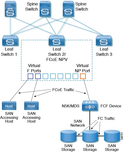


 Feedback