FCoE Connections

This chapter contains the following sections:

Supporting Fibre Channel over Ethernet Traffic on the Cisco ACI Fabric

Cisco Application Centric Infrastructure (ACI) enables you to configure and manage support for Fibre Channel over Ethernet (FCoE) traffic on the Cisco ACI fabric.

FCoE is a protocol that encapsulates Fibre Channel packets within Ethernet packets, thus enabling storage traffic to move seamlessly between a Fibre Channel SAN and an Ethernet network.

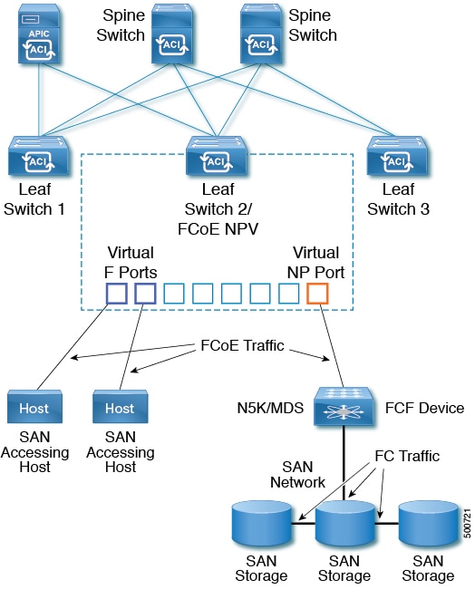
A typical implementation of FCoE protocol support on the Cisco ACI fabric enables hosts located on the Ethernet-based Cisco ACI fabric to communicate with SAN storage devices located on a Fibre Channel network. The hosts are connecting through virtual F ports deployed on an Cisco ACI leaf switch. The SAN storage devices and Fibre Channel network are connected through a Fibre Channel Forwarding (FCF) bridge to the Cisco ACI fabric through a virtual NP port, deployed on the same Cisco ACI leaf switch as is the virtual F port. Virtual NP ports and virtual F ports are also referred to generically as virtual Fibre Channel (vFC) ports.


Note


In the FCoE topology, the role of the Cisco ACI leaf switch is to provide a path for FCoE traffic between the locally connected SAN hosts and a locally connected FCF device. The leaf switch does not perform local switching between SAN hosts, and the FCoE traffic is not forwarded to a spine switch.


Topology Supporting FCoE Traffic Through Cisco ACI

The topology of a typical configuration supporting FCoE traffic over the Cisco ACI fabric consists of the following components:

Figure 1. Cisco ACI Topology Supporting FCoE Traffic


  • One or more Cisco ACI leaf switches configured through Fibre Channel SAN policies to function as an NPV backbone.

  • Selected interfaces on the NPV-configured leaf switches configured to function as virtual F ports, which accommodate FCoE traffic to and from hosts running SAN management or SAN-consuming applications.

  • Selected interfaces on the NPV-configured leaf switches configured to function as virtual NP ports, which accommodate FCoE traffic to and from a Fibre Channel Forwarding (FCF) bridge.

The FCF bridge receives Fibre Channel traffic from Fibre Channel links typically connecting SAN storage devices and encapsulates the Fibre Channel packets into FCoE frames for transmission over the Cisco ACI fabric to the SAN management or SAN Data-consuming hosts. It receives FCoE traffic and repackages it back to the Fibre Channel for transmission over the Fibre Channel network.


Note


In the above Cisco ACI topology, FCoE traffic support requires direct connections between the hosts and virtual F ports and direct connections between the FCF device and the virtual NP port.


Cisco Application Policy Infrastructure Controller (APIC) servers enable an operator to configure and monitor the FCoE traffic through the Cisco APIC GUI, or NX-OS-style CLI, or through application calls to the REST API.

Topology Supporting FCoE Initialization

In order for FCoE traffic flow to take place as described, you must also set up separate VLAN connectivity over which SAN Hosts broadcast FCoE Initialization protocol (FIP) packets to discover the interfaces enabled as F ports.

vFC Interface Configuration Rules

Whether you set up the vFC network and EPG deployment through the Cisco APIC GUI, NX-OS-style CLI, or the REST API, the following general rules apply across platforms:

  • F port mode is the default mode for vFC ports. NP port mode must be specifically configured in the Interface policies.

  • The load balancing default mode is for leaf-switch or interface level vFC configuration is src-dst-ox-id.

  • One VSAN assignment per bridge domain is supported.

  • The allocation mode for VSAN pools and VLAN pools must always be static.

  • vFC ports require association with a VSAN domain (also called Fibre Channel domain) that contains VSANs mapped to VLANs.

Fibre Channel over Ethernet Guidelines and Limitations

The VLAN used for FCoE should have vlanScope set to Global. Setting vlanScope to portLocal is not supported for FCoE. The value is set using the Layer 2 interface policy (l2IfPol).

Fibre Channel over Ethernet Supported Hardware

FCoE is supported on the following switches:

  • N9K-C93180LC-EX

    When 40 Gigabit Ethernet (GE) ports are enabled as FCoE F or NP ports, they cannot be enabled for 40GE port breakout. FCoE is not supported on breakout ports.

  • N9K-C93108TC-FX

  • N9K-C93108TC-EX (only FCoE NPV)

  • N9K-C93180YC-EX

  • N9K-C93180LC-EX

    Support includes FCoE on FEX ports.

  • N9K-C93180YC-FX

    Support includes 10/25G ports (1-48), 40G ports (1/49-54), 4x10G breakout ports (1/49-54), and FCoE on FEX ports.

FCoE is supported on the following Nexus FEX devices:

  • N2K-C2348UPQ-10GE

  • N2K-C2348TQ-10GE

  • N2K-C2232PP-10GE

  • N2K-B22DELL-P

  • N2K-B22HP-P

  • N2K-B22IBM-P

  • N2K-B22DELL-P-FI

Configuring FCoE Using the APIC GUI

FCoE GUI Configuration

FCoE Policy, Profile, and Domain Configurations

You can use the APIC GUI under the Fabric Access Policies tab to configure policies, policy groups, and profiles to enable customized and scaled-out deployment and assignment of FCoE supporting F and NP ports on your ACI leaf switches. Then, under the APIC the Tenant tab, you can configure EPG access to those ports.

Policies and Policy Groups

APIC policies and policy groups you create or configure for FCoE support include the following:

Access Switch Policy Group

The combination of switch-level policies that support FCoE traffic through ACI leaf switches.

You can associate this policy group with a leaf profile to enable FCoE support on designated ACI leaf switches.

This policy group consists of the following policies:

  • Fibre Channel SAN Policy

    Specifies the EDTOV, RATOV, and MAC Address prefix (also called the FC map) values used by the NPV leaf.

  • Fibre Channel Node Policy

    Specifies the load balance options and FIP keep alive intervals that apply to FCoE traffic associated with this switch policy group.

Interface Policy Groups

The combination of interface-level policies that support FCoE traffic through interfaces on ACI leaf switches.

You can associate this policy group with an FCoE supportive interface profile to enable FCoE support on designated interfaces.

You configure two interface policy groups: One policy group for F ports, and one policy group for NP ports.

The following policies in the interface policy group apply to FCoE enablement and traffic:

  • Priority Flow Control Policy

    Specifies the state of priority flow control (PFC) on the interfaces to which this policy group is applied.

    This policy specifies under what circumstances QoS-level priority flow control will be applied to FCoE traffic.

  • Fibre Channel Interface Policy

    Specifies whether the interfaces to which this policy group is applied are to be configured as F ports or NP ports.

  • Slow Drain Policy

    Specifies the policy for handling FCoE packets that are causing traffic congestion on the ACI Fabric.

Global Policies

The APIC global policies whose settings can affect the performance characteristics of FCoE traffic on the ACI fabric.

The Global QOS Class Policies for Level1, Level2, Level4, Level5, or Level6 connections, contain the following settings that affect FCoE traffic on the ACI fabric:

  • PFC Admin State must be set to Auto

    Specifies whether to enable priority flow control to this level of FCoE traffic (default value is false).

  • No Drop COS

    Specifies whether to enable a no-drop policy for this level of FCoE traffic designated with a certain Class of Service (CoS) level.

    Note: QoS level enabled for PFC and FCoE no-drop must match with the Priority Group ID enabled for PFC on CNA.

    Note: Only one QoS level can be enabled for no-drop and PFC, and the same QoS level must be associated with FCoE EPGs.

  • QoS Class—Priority flow control requires that CoS levels be globally enabled for the fabric and assigned to the profiles of applications that generate FCoE traffic.

    CoS Preservation must also be enabled—Navigate to Fabric > Access Policies > Policies > Global > QoS Class and enable Preserve COS Dot1p Preserve.


Note


Some legacy CNAs may require the Level2 Global QoS Policy to be used as the No Drop PFC, FCoE (Fibre Channel over Ethernet) QoS Policy. If your Converged Network Adapters (CNAs) are not logging into the fabric, and you have noticed that no FCoE Initiation Protocol (FIP) frames are being sent by the CNAs, try enabling Level2 as the FCoE QoS policy. The Level2 policy must be attached to the FCoE EPGs in use and only one QoS level can be enabled for PFC no-drop.


Profiles

APIC profiles that you can create or configure for FCoE support include the following:

Leaf Profile

Specifies the ACI Fabric leaf switches on which to configure support of FCoE traffic.

The combination of policies contained in the access switch policy group can be applied to the leaf switches included in this profile.

Interface Profiles

Specifies a set of interfaces on which to deploy F Ports or NP Ports.

You configure at least two leaf interface profiles: One interface profile for F ports, and one interface profile for NP ports.

The combination of policies contained in the interface policy group for F ports can be applied to the set of interfaces included in the interface profile for F ports.

The combination of policies contained in the interface policy group for NP ports can be applied to the set of interfaces included in the interface profile for NP ports.

Attached Entity Profile

Binds the interface policy group settings with the Fibre Channel domain mapping.

Domains

Domains that you create of configure for FCoE support include the following:

Physical Domain

A virtual domain created to support LANs for FCoE VLAN Discovery. The Physical domain will specify the VLAN pool to support FCoE VLAN discovery.

Fibre Channel Domain

A virtual domain created to support virtual SANs for FCoE connections.

A Fibre Channel domain specifies a VSAN pool, VLAN pool and the VSAN Attribute over which the FCoE traffic is carried.

  • VSAN pool - a set of virtual SANs which you associate with existing VLANs. Individual VSANs can be assigned to associated FCoE-enabled interfaces in the same way that VLANs can be assigned to those interfaces for Ethernet connectivity.

  • VLAN pool - the set of VLANs available to be associated with individual VSANs.

  • VSAN Attribute - The mapping of a VSAN to a VLAN.

Tenant Entities

Under the Tenant tab, you configure bridge domain and EPG entities to access the FCoE ports and exchange the FCoE traffic.

The entities include the following:

Bridge Domain (configured for FCoE support)

A bridge domain created and configured under a tenant to carry FCoE traffic for applications that use FCoE connections.

Application EPG

The EPG under the same tenant to be associated with the FCoE bridge domain.

Fibre Channel Path

Specifies the interfaces enabled as FCoE F ports or NP ports to be associated with the selected EPG. After you associate the Fibre Channel path with an EPG the FCoE interface is deployed in the specified VSAN.

Deploying FCoE vFC Ports Using the APIC GUI

The APIC GUI enables you to create customized node policy groups, leaf profiles, interface policy groups, interface profiles, and virtual SAN domains that system administrators can re-use to ensure that all interfaces they designate as F ports or NP ports to handle FCoE traffic have consistent FCoE-related policies applied.

Before you begin

Procedure


Step 1

Create an FCoE supportive switch policy group to specify and combine all the leaf switch policies that support FCoE configuration.

This policy group will be applied to the leaf switches that you want to serve as NPV hosts.

  1. In the APIC GUI, starting on the APIC menu bar, click Fabric > Access Policies > Switches > Leaf Switches > Policy Groups.

  2. Right-click Policy Groups and click Create Access Switch Policy Group.

  3. In the Create Access Switch Policy Group dialog, specify the settings described below and then click Submit.

Policy Description
Name

Identifies the switch policy group.

Enter a name that indicates the FCoE supportive function of this switch policy group. For example, fcoe_switch_policy_grp.

Fibre Channel SAN Policy

Specifies the following SAN Policy values:

  • FC Protocol EDTOV (default: 2000)

  • FC Protocol RATOV (default : 10000)

  • MAC address prefix (also called FC map) used by the leaf switch. This value should match the value of the peer device connected on the same port. Typically the default value OE:FC:00 is used.

Click the drop-down option box.

  • To use the default EDTOV, RATOV, and MAC address prefix values, click default.

  • To use the value specified in an existing policy, click that policy.

  • To create a new policy to specify a new customized MAC address prefix, click Create Fibre Channel SAN Policy and follow the prompts.

Step 2

Create a leaf profile for leaf switches to support FCoE traffic.

This profile specifies a switch or set of leaf switches to assign the switch policy group that was configured in the previous step. This association enables that set of switches to support FCoE traffic with pre-defined policy settings.

  1. Starting at the APIC menu bar, click Fabric > Access Policies > Switches > Leaf Switches > Profiles

  2. Right-click Leaf Profiles, then click Create Leaf Profile.

  3. In the Create Leaf Profile dialog create and name the leaf profile (for example: NPV-1)

  4. Also in the Create Leaf Profile dialog, locate the Leaf Selectors table, click +to create a new table row and specify the leaf switches to serve as NPV devices.

  5. In the new table row choose a leaf name, blocks, and assign the switch policy group that you created in the previous step.

  6. Click Next and then click Finish.

Step 3

Create at least two FCoE-supportive interface policy groups: one to combine all policies that support FCoE F port interfaces, and one to combine all policies that support FCoE NP port interfaces.

These interface policy groups are to be applied to the interface profiles that are applied to interfaces that are to serve as F ports and NP ports.
  1. On the APIC menu bar, click Fabric > Access Policies > Interfaces > Leaf Interfaces > Policy Groups.

  2. Right-click Policy Groups, then, depending on how port access is configured, click one of the following options: Create Leaf Access Port Policy Group, Create PC Interface Port Policy, or Create vPC Interface Port Policy Group.

    Note

     
  3. In the policy group dialog, specify for inclusion the Fibre Channel Interface policy, the slow drain policy, and the priority flow control policy you configure.

Policy Description
Name

Name of this policy group.

Enter a name that indicates the FCoE supportive function of this Leaf Access Port Policy Group and the port type, (F or NP) that it is intended to support, for example: fcoe_f_port_policy or fcoe_np_port_policy.

Priority Flow Control Policy

Specifies the state of the Priority Flow Control (PFC) on the interfaces to which this policy group is applied.

Options include the following:

  • Auto (the default value) Enables priority flow control (PFC) on local port on the no-drop CoS as configured, on the condition that values advertised by the DCBX and negotiated with the peer succeed. Failure causes priority flow control to be disabled on the no-drop CoS.

  • Off disables FCoE priority flow control on the local port under all circumstances.

  • On enables FCoE PFC on the local port under all circumstances.

Click the drop-down option box:

  • To use the default values, click default.

  • To use the value specified in an existing policy, click that policy.

  • To create a new policy specifying different values, click Create Priority Flow Control Policy and follow the prompts.

Note


PFC requires that Class of Service (CoS) levels be globally enabled for the fabric and assigned to the profiles of applications that generate FCoE traffic. Also CoS Preservation must be enabled. To enable it, navigate to Fabric > Access Policies > Policies > Global > QoS Class and enable Preserve COS Dot1p Preserve.

Slow Drain Policy Specifies how to handle FCoE packets that are causing traffic congestion on the ACI fabric. Options include the following:
  • Congestion Clear Action (default: disabled)

    Action to be taken during FCoE traffic congestion. Options include:

    • Err - disable - Disable the port.

    • Log - Record congestion in the Event Log.

    • Disabled- Take no action.

  • Congestion Detect Multiplier (default: 10)

    The number of pause frames received on a port that triggers a congestion clear action to address FCoE traffic congestion.

  • Flush Admin State

    • Enabled - Flush the buffer.

    • Disabled - Don't flush the buffer.

  • Flush Timeout (default: 500 milliseconds)

    Threshold in milliseconds to trigger buffer flush drop during congestion.

  • To use the default values, click default.

  • To use the value specified in an existing policy, click that policy.

  • To create a new policy specifying different values, click Create Slow Drain Policy and follow the prompts.

Step 4

Create at least two interface profiles: one profile to support F port connections, one profile to support NP port connections, and optional additional profiles to be associated with additional port policy variations.

  1. Starting at the APIC bar menu click Fabric > Access Policies > Interfaces > Leaf Interfaces > Profiles.

  2. Right-click Profiles and choose Create Leaf Interface Profile.

  3. In the Create Leaf Interface Profile dialog, enter a descriptive name for the profile, for example,FCoE_F_port_Interface_profile-1.

  4. Locate the Interface Selectors table and click + to display the Create Access Port Selector dialog. This dialog enables you to display a range of interfaces and apply settings to the fields described in the following table.

Option Description
Name

A descriptive name for this port selector.

Interface IDs

Specifies the set of interfaces to which this range applies.

  • To include all interfaces in the switch, choose All.

  • To include an individual interface in this range, specify single Interface ID, for example: 1/20.

  • To include a range of interfaces in this range, enter the lower and upper values separated by a dash, for example: 1/10 - 1/15.

Note


Specify separate, non-overlapping ranges of interfaces when configuring interface profiles for F ports and an NP port.

Interface Policy Group

The name of either the F port interface policy group or the NP port policy group that you configured in the previous step.

  • To designate the interfaces included in this profile as F ports, choose the interface policy group that you configured for F ports.

  • To designate the interfaces included in the profile as NP ports, choose the interface policy group that you configured for NP ports.

Step 5

Click Submit. Repeat the previous step so that you at least have interface profiles for both F ports and an NP port.

Step 6

Configure whether to apply global QoS policies to FCoE traffic.

You can specify different QoS policies to different levels (1, 2, 4, 5, or 6) of FCoE traffic.

  1. Starting at the APIC bar menu click Fabric > Access Policies > Policies > Global > QoS Class and enable the Preserve CoS flag in the QoS Class pane.

  2. In the QoS Class - Level 1, QoS Class - Level 2, QoS Class - Level 4, QoS Class - Level 5, or QoS Class - Level 6 dialog, edit the following fields to specify the PFC and no-drop CoS. Then click Submit.

    Note


    Only 1 Level can be configured for PFC and no-drop CoS.

Policy Description
PFC Admin State

Whether to enable priority flow control to this level of FCoE traffic (default value is false).

Enabling priority flow control sets the Congestion Algorithm for this level of FCoE traffic to no-drop.

No-Drop-CoS

The CoS level to impose no drop FCoE packet handling even in the case of FCoE traffic congestion.

Step 7

Define a Fibre Channel domain. Create a set of virtual SANs (VSANs) and map them to set of existing VLANs.

  1. Starting at the APIC bar menu click Fabric > Access Policies > Physical and External Domains > Fibre Channel Domains.

  2. Right-click Fibre Channel Domains and click Create Fibre Channel Domain.

  3. In the Fibre Channel Domain dialog, specify the following settings:

Option Description/Action
Name

Specifies the name or label you want to assign the VSAN domain you are creating. (For example: vsan-dom2)

VSAN Pool

The pool of VSANs assigned to this domain.

  • To select an existing VSAN pool, click the drop-down and choose a listed pool. If you want to revise it, click the Edit icon.

  • To create a VSAN pool, click Create a VSAN Pool.

If you open the dialog to create a VSAN pool, follow the prompts configure the following:

  • A Static resource allocation method to support FCoE.

  • a range of VSANs that will be available to assign to FCoE F port interfaces and NP port interfaces.

    Note


    Minimum range value is 1. Maximum range value is 4078.

    Configure multiple ranges of VSANs if necessary.

VLAN Pool

The pool of VLANS available to be mapped to by the members of the VSAN pool.

A VLAN pool specifies numerical ranges of VLANs you want available to support FCoE connections for this domain. The VLANs in the ranges you specify are available for VSANs to map to them.

  • To select an existing VLAN pool, click the drop-down and choose a listed pool. If you want to revise it, click the Edit icon.

  • To create a VLAN pool, click Create a VLAN Pool.

If you open the dialog to create a VLAN pool, follow the prompts configure the following:

  • A Static resource allocation method to support FCoE.

  • a range of VLANs that will be available for VSANs to map to.

    Note


    Minimum range value is 1. Maximum range value is 4094.

    Configure multiple ranges of VLANs if necessary.

VSAN Attr

The VSAN Attributes map for this domain.

The VSAN Attributes map VSANs in the VSAN pool to VLANs in the VLAN pool.

  • To select an existing VSAN Attributes map, click the drop-down and choose a listed map. If you want to revise it, click the Edit icon.

  • To create a VSAN Attributes map, click Create VSAN Attributes.

If you open the dialog to configure the VSAN attributes, follow the prompts configure the following:

  • The appropriate load balancing option (src-dst-ox-id or src-dst-id).

  • Mapping of individual VSANs to individual VLANs, for example: vsan-8 to vlan-10

    Note


    Only VSANs and VLANs in the ranges you specified for this domain can be mapped to each other.

Step 8

Create an attached entity profile to bind the Fibre Channel domain with the interface policy group.

  1. On the APIC menu bar, click Fabric > Access Policies > Interfaces > Leaf Interfaces > Policy Groups > interface_policy_group_name .

    In this step interface_policy_group_name is the interface policy group that you defined in Step 3.

  2. In the interface policy group dialog, Click the Attached Entity Profile drop-down and choose an existing Attached Entity Profile or click Create Attached Entity Profile to create a new one.

  3. In the Attached Entity Profile dialog specify the following settings:

Field Description
Name

A name for this Attached Entity Profile.

Domains To Be Associated To Interfaces

Lists the domain to be associated with the interface policy group.

In this case, choose the Fibre Channel domain you configured in Step 7.

Click Submit.

Step 9

Associate the leaf profile and the F port and NP port interface profiles.

  1. Starting at the APIC menu bar, click Fabric > Access Policies > Switches > Leaf Switches > Profiles then click the name of the leaf profile you configured in Step 2.

  2. In the Create Leaf Profile dialog, locate the Associated Interface Selector Profiles table, click +to create a new table row and choose the F port interface profile you created in Step 4.

  3. Again on the Associated Interface Selector Profiles table, click +to create a new table row and choose the NP port interface profile you created in Step 4.

  4. Click Submit.


What to do next

After successful deployment of virtual F ports and NP ports to interfaces on the ACI fabric, the next step is for system administrators to enable EPG access and connection over those interfaces.

For more information, see Deploying EPG Access to vFC Ports Using the APIC GUI.

Deploying EPG Access to vFC Ports Using the APIC GUI

After you have configured ACI fabric entities to support FCoE traffic and F port and NP port functioning of designated interfaces, your next step is to configure EPG access to those ports.

Before you begin

  • The ACI fabric is installed.

  • A Fibre Channel Forwarding (FCF) switch, connected to a FC network (for example, SAN storage), is physically attached by Ethernet to an ACI leaf switch port.

  • A host application that needs to access the FC network is physically attached by Ethernet to a port on the same ACI leaf switch.

  • Leaf policy groups, leaf profiles, interface policy groups, interface profiles, and Fibre Channel domains have all been configured to support FCoE traffic.

Procedure


Step 1

Under an appropriate tenant configure an existing bridge domain to support FCoE or create a bridge domain to support FCoE.

Option: Actions
To configure an existing bridge domain for FCoE
  1. Click Tenant > tenant_name > Networking > Bridge Domains > bridge_domain_name .

  2. In the Type field of the bridge domain's Properties panel, click fc.

  3. Click Submit.

To create a new bridge domain for FCoE
  1. Click Tenant > tenant_name > Networking > Bridge Domains > Actions > Create a Bridge Domain.

  2. In the Name field of the Specify Bridge Domain for the VRF dialog, enter a bridge domain name.

  3. In the Type field of Specify Bridge Domain for the VRF dialog, click fc.

  4. In VRF field select a VRF from the drop-down or click Create VRF to create and configure a new VRF.

  5. Finish the bridge domain configuration.

  6. Click Submit.

Step 2

Under the same tenant, configure an existing EPG or create a new EPG to associate with the FCoE-configured bridge domain.

Option: Actions
To associate an existing EPG
  1. Click Tenant > <tenant_name> > Application Profiles > <application_profile_name> > Application EPGs > <epg_name> .

  2. In the QoS class field choose the quality of service (Level1, Level2, Level4, Level5, or Level6) to assign to traffic generated by this EPG.

    If you configured one of the QoS levels for priority-flow control no-drop congestion handling and you want FCoE traffic handled with no-dropped packet priority, assign that QoS level to this EPG.

  3. In the Bridge Domain field of the EPG's Properties panel, click the drop-down list and choose the name of a bridge domain configured for Type: fcoe.

  4. Click Submit.

    Note


    If you change the Bridge Domain field, you must wait 30-35 seconds between changes. Changing the Bridge Domain field too rapidly causes vFC interfaces on the NPV Switch to fail and a switch reload must be executed.

To create and associate a new EPG
  1. Click Tenant > <tenant_name> > Application Profiles > <application_profile_name> > Application EPGs.

  2. Right-click Application EPGs and click Create Application EPG.

  3. In the QoS class field choose the quality of service (Level1, Level2, Level4, Level5, or Level6) to assign to traffic generated by this EPG.

    If you configured one of the QoS levels for priority-flow control no-drop congestion handling and you want FCoE traffic handled with no-dropped packet priority, assign that QoS level to this EPG.

  4. In the Bridge Domain field of the Specify the EPG Identity dialog, click the drop-down list and choose the name of a bridge domain configured for Type: fcoe.

    Note


    If you change the Bridge Domain field, you must wait 30-35 seconds between changes. Changing the Bridge Domain field too rapidly causes vFC interfaces on the NPV Switch to fail and a switch reload must be executed.

  5. Finish the bridge domain configuration.

  6. Click Finish.

Step 3

Add a Fibre Channel Domain association with the EPG.

  1. Click Tenant > <tenant_name> > Application Profiles > <application_profile_name> > Application EPGs > <epg_name> > Domains (VMs and Bare Metal).

  2. Right-click Domains (VMs and Bare Metal) and click Add Fibre Channel Domain Association.

  3. In the Add Fibre Channel Domain Association dialog, locate the Fibre Channel Domain Profile Field.

  4. Click the drop-down list and choose the name of the Fibre Channel domain that you previously configured.

  5. Click Submit.

Step 4

Under the associated EPG define a Fibre Channel path.

The Fibre Channel path specifies the interfaces enabled as FCoE F ports or NP ports to be associated with the selected EPG.

  1. Click Tenant > <tenant_name> > Application Profiles > <application_profile_name> > Application EPGs > <epg_name> > Fibre Channel (Paths).

  2. Right-click Fibre Channel (Paths) and click Deploy Fibre Channel.

  3. In the Deploy Fibre Channel dialog configure the following settings:

Option: Actions
Path Type The type of interface (Port, Direct Port Channel, or Virtual Port Channel) being accessed for sending and receiving FCoE traffic.
Path The Node-interface path through which FCoE traffic associated with the selected EPG will flow.

Click the drop-down list and choose from the listed interfaces. .

Note

 
Choose only the interfaces previously configured as F ports or NP ports. Choosing interfaces that you did not configure causes only default values to apply to those interfaces.

Note


To deploy FCoE over FEX, select the FEX ports previously configured.

VSAN

The VSAN which will use the interface selected in the Path field.

Note


The specified VSAN must be in the range of VSANs that was designated for the VSAN pool.

In most cases, all interfaces that this EPG is configured to access must be assigned the same VSAN, unless you specify a Fibre Channel path over a Virtual Port Channel (VPC) connection. In that case, you can specify two VSANs, one for each leg of the connection.

VSAN Mode

The mode (Native or Regular) in which the selected VSAN accesses the selected interface.

Every interface configured for FCoE support, requires one VSAN and only one VSAN configured for Native mode. Any additional VSANs assigned to the same interface must access it in Regular mode.

Pinning label

(Optional) This option applies only if you are mapping access to an F port and it is necessary to bind this F port with a specific uplink NP port. It associates a pinning label (pinning label 1 or pinning label 2) with a specific NP port. You can then assign that pinning label to the target F port. This association causes the associated NP port to serve in all cases as the uplink port to the target F Port.

Choose a pinning label and associate it with an interface configured as an NP port.

This option implements what is also referred to as "traffic-mapping."

Note


The F port and the associated Pinning Label NP port must be on the same Leaf switch.

Step 5

Click Submit.

Step 6

Repeat Steps 4 and 5 for every FCoE enabled interface to which you are mapping EPG access.

Step 7

Verify successful deployment, as follows:

  1. Click Fabric > Inventory > Pod_name > leaf_name > Interfaces > VFC interfaces.

The interfaces on which you deployed ports are listed under VFC Interfaces.

What to do next

After you have set up EPG access to the vFC interfaces, the final step is to set up the network supporting the FCoE initialization protocol (FIP), which enables discovery of those interfaces.

For more information, see Deploying the EPG to Support the FCoE Initiation Protocol.

Deploying the EPG to Support the FCoE Initiation Protocol

After you have configured FCoE EPG access to your server ports, you must also configure EPG access to support the FCoE Initiation Protocol (FIP).

Before you begin

Procedure


Step 1

Under the same tenant configure an existing bridge domain to support FIP or create a regular bridge domain to support FIP.

Option: Actions
To configure an existing bridge domain for FCoE
  1. Click Tenant > tenant_name > Networking > Bridge Domains > bridge_domain_name .

  2. In the Type field of the bridge domain's Properties panel, click Regular.

  3. Click Submit.

To create a new bridge domain for FCoE
  1. Click Tenant > tenant_name > Networking > Bridge Domains > Actions > Create a Bridge Domain.

  2. In the Name field of the Specify Bridge Domain for the VRF dialog, enter a bridge domain name.

  3. In the Type field of Specify Bridge Domain for the VRF dialog, click Regular.

  4. In VRF field select a VRF from the drop-down or click Create VRF to create and configure a new VRF.

  5. Finish the bridge domain configuration.

  6. Click Submit.

Step 2

Under the same tenant, configure an existing EPG or create a new EPG to associate with the regular-type bridge domain.

Option: Actions
To associate an existing EPG
  1. Click Tenant > tenant_name > Application Profiles > ap1 > Application EPGs > epg_name .

  2. In the Bridge Domain field of the EPG's Properties panel, click the drop-down list and choose the name of the regular bridge domain that you just configured to support FIP.

  3. Click Submit.

To create and associate a new EPG
  1. Click Tenant > tenant_name > Application Profiles > ap1 > Application EPGs.

  2. Right-click Application EPGs and click Create Application EPG.

  3. In the Bridge Domain field of the Specify the EPG Identity dialog, click the drop-down list and choose the name of the regular bridge domain that you just configured to support FIP.

  4. Finish the bridge domain configuration.

  5. Click Finish.

Step 3

Add a Physical Domain association with the EPG.

  1. Click Tenant > tenant_name > Application Profiles > ap1 > Application EPGs > epg_name > Domains & Bare Metal.

  2. Right-click Domains & Bare Metal and click Add Physical Domain Association.

  3. In the Add Physical Domain Association dialog, locate Physical Domain Profile Field.

  4. Click the drop-down list and choose the name of the physical domain that contains the LAN that intended for use in FIP support.

  5. Click Submit.

Step 4

Under the associated EPG define a path.

The path specifies the interfaces enabled as FCoE F ports or NP ports to be associated with the selected EPG.

  1. Click Tenant > tenant_name > Application Profiles > ap1 > Application EPGs > epg_name > Static Ports.

  2. Right-click Static Ports and click Deploy Static EPG on PC, VPC, or Interface.

  3. In the Path Type field, specify the port type (Port, Direct Port Channel, or Virtual Port Channel) on which you want to deploy an F mode vFC.

  4. In the Path field, specify all the paths on which are deployed the F ports.

  5. Choose the VLAN Encap that you want to use as your FCoE VLAN discovery and 802.1p(access) as port mode.

  6. Click Submit.


The FCoE components will begin the discovery process to initiate the operation of the FCoE network.

Undeploying FCoE Connectivity Using the APIC GUI

To undo FCoE enablement of leaf switch interfaces on the ACI fabric, delete the Fibre Channel path and Fibre Channel domain and its elements that you defined in Deploying FCoE vFC Ports Using the APIC GUI.

Note


If during clean up you delete the Ethernet configuration object (infraHPortS) for a vFC port (for example, in the Interface Selector table on the Leaf Interface Profiles page of the GUI), the default vFC properties remain associated with that interface. For example it the interface configuration for vFC NP port 1/20 is deleted, that port remains a vFC port but with default F port setting rather than non-default NP port setting applied.


Before you begin

You must know the name of the Fibre Channel path and Fibre Channel domain including its associated VSAN pool, VLAN pool, and VSAN Attributes map that you specified during FCoE deployment.

Procedure


Step 1

Delete the associated Fibre Channel path to undeploy vFC from the port/vsan whose path was specified on this deployment.

This action removes vFC deployment from the port/vsan whose path was specified on this deployment.

  1. Click Tenants > tenant_name > Application Profiles > app_profile_name > Application EPGs > app_epg_name > Fibre Channel (Paths). Then right-click the name of the target Fibre Channel path and choose Delete.

  2. Click Yes to confirm the deletion.

Step 2

Delete the VLAN to VSAN map that you configured when you defined the Fibre Channel domain.

This action removes vFC deployment from all the elements defined in the map.

  1. Click Fabric > Access Policies > Pools > VSAN Attributes. Then right-click the name of the target map and choose Delete.

  2. Click Yes to confirm the deletion.

Step 3

Delete the VLAN and VSAN pools that you defined when you defined the Fibre Channel domain.

This action eliminates all vFC deployment from the ACI fabric.

  1. Click Fabric > Access Policies > Pools > VSAN and then, right-click the name of the target VSAN pool name and choose Delete.

  2. Click Yes to confirm the deletion.

  3. Click Fabric > Access Policies > Pools > VLAN then, right-click the target VLAN pool name and choose Delete.

  4. Click Yes to confirm the deletion.

Step 4

Delete the Fibre Channel Domain that contained the VSAN pool, VLAN pool, and Map elements you just deleted.

  1. Click Tenants > tenant_name > Application Profiles > Fibre Channel Domains. Then right-click the name of the target Fibre Channel Domain and choose Delete.

  2. Click Yes to confirm the deletion.

Step 5

You can delete the tenant/EPG/App and the selectors if you don’t need them.

Option Action
If you want to delete the associated application EPG but save the associated tenant and application profile:

Click Tenants > tenant_name > Application Profiles > app_profile_name > Application EPGs, right-click the name of the target application EPG, choose Delete, then click Yes to confirm deletion.

If you want to delete the associated application profile but save the associated tenant:

Click Tenants > tenant_name > Application Profiles, right-click the name of the target application profile, choose Delete, then click Yes to confirm deletion.

If you want to delete the associated tenant:

Click Tenants > , right-click the name of the target tenant, choose Delete, then click Yes to confirm deletion.


Configuring FCoE Using the NX_OS Style CLI

FCoE NX-OS Style CLI Configuration

Configuring FCoE Connectivity Without Policies or Profiles Using the NX-OS Style CLI

The following sample NX-OS style CLI sequences configure FCoE connectivity for EPG e1 under tenant t1 without configuring or applying switch-level and interface-level policies and profiles.

Procedure

  Command or Action Purpose

Step 1

Under the target tenant configure a bridge domain to support FCoE traffic.

Example:

apic1(config)# tenant t1
apic1(config-tenant)# vrf context v1
apic1(config-tenant-vrf)# exit
apic1(config-tenant)# bridge-domain b1
apic1(config-tenant-bd)# fc
apic1(config-tenant-bd)# vrf member v1
apic1(config-tenant-bd)# exit
apic1(config-tenant)# exit

The sample command sequence creates bridge domain b1 under tenant t1 configured to support FCoE connectivity.

Step 2

Under the same tenant, associate the target EPG with the FCoE-configured bridge domain.

Example:

apic1(config)# tenant t1
apic1(config-tenant)# application a1
apic1(config-tenant-app)# epg e1
apic1(config-tenant-app-epg)# bridge-domain member b1
apic1(config-tenant-app-epg)# exit
apic1(config-tenant-app)# exit
apic1(config-tenant)# exit

The sample command sequence creates EPG e1 and associates that EPG with the FCoE-configured bridge domain b1.

Step 3

Create a VSAN domain, VSAN pools, VLAN pools and VSAN to VLAN mapping.

Example:

A
apic1(config)# vsan-domain dom1
apic1(config-vsan)# vsan 1-10
apic1(config-vsan)# vlan 1-10
apic1(config-vsan)# fcoe vsan 1 vlan 1 loadbalancing src-dst-ox-id 
apic1(config-vsan)# fcoe vsan 2 vlan 2 

Example:

B
apic1(config)# template vsan-attribute pol1
apic1(config-vsan-attr)#  fcoe vsan 2 vlan 12 loadbalancing src-dst-ox-id
apic1(config-vsan-attr)#  fcoe vsan 3 vlan 13 loadbalancing src-dst-ox-id
apic1(config-vsan-attr)#  exit
apic1(config)#  vsan-domain dom1
apic1(config-vsan)# vsan 1-10
apic1(config-vsan)# vlan 1-10
apic1(config-vsan)# inherit vsan-attribute pol1
apic1(config-vsan)# exit

In Example A, the sample command sequence creates VSAN domain, dom1 with VSAN pools and VLAN pools, maps VSAN 1 to VLAN 1 and maps VSAN 2 to VLAN 2

In Example B, an alternate sample command sequence creates a reusable VSAN attribute template pol1 and then creates VSAN domain dom1, which inherits the attributes and mappings from that template.

Step 4

Create the physical domain to support the FCoE Initialization (FIP) process.

Example:


apic1(config)# vlan-domain fipVlanDom
apic1(config-vlan)# vlan 120
apic1(config-vlan)# exit

In the example, the command sequence creates a regular VLAN domain, fipVlanDom, which includes VLAN 120 to support the FIP process.

Step 5

Under the target tenant configure a regular bridge domain.

Example:

apic1(config)# tenant t1
apic1(config-tenant)# vrf context v2
apic1(config-tenant-vrf)# exit
apic1(config-tenant)# bridge-domain fip-bd 
apic1(config-tenant-bd)# vrf member v2
apic1(config-tenant-bd)# exit
apic1(config-tenant)# exit 

In the example, the command sequence creates bridge domain fip-bd.

Step 6

Under the same tenant, associate this EPG with the configured regular bridge domain.

Example:

apic1(config)# tenant t1
apic1(config-tenant)# application a1
apic1(config-tenant-app)# epg epg-fip 
apic1(config-tenant-app-epg)# bridge-domain member fip-bd 
apic1(config-tenant-app-epg)# exit
apic1(config-tenant-app)# exit
apic1(config-tenant)# exit

In the example, the command sequence associates EPG epg-fip with bridge domain fip-bd.

Step 7

Configure a VFC interface with F mode.

Example:

A
apic1(config)# leaf 101
apic1(config-leaf)# interface ethernet 1/2
apic1(config-leaf-if)# vlan-domain member fipVlanDom 
apic1(config-leaf-if)# switchport trunk native vlan 120 tenant t1 application a1 epg epg-fip 
apic1(config-leaf-if)# exit                            
apic1(config-leaf)# exit
apic1(config-leaf)# interface vfc 1/2
apic1(config-leaf-if)# switchport mode f
apic1(config-leaf-if)# vsan-domain member dom1 
apic1(config-leaf-if)# switchport vsan 2 tenant t1 application a1 epg e1 
apic1(config-leaf-if)# switchport trunk allowed vsan 3 tenant t1 application a1 epg e2
apic1(config-leaf-if)# exit

Example:

B
apic1(config)# vpc context leaf 101 102
apic1(config-vpc)# interface vpc vpc1
apic1(config-vpc-if)# vlan-domain member vfdom100
apic1(config-vpc-if)# vsan-domain member dom1 
apic1(config-vpc-if)# #For FIP discovery
apic1(config-vpc-if)# switchport trunk native vlan 120 tenant t1 application a1 epg epg-fip
apic1(config-vpc-if)# switchport vsan 2 tenant t1 application a1 epg e1
apic1(config-vpc-if)# exit
apic1(config-vpc)# exit
apic1(config)# leaf 101-102
apic1(config-leaf)# interface ethernet 1/3
apic1(config-leaf-if)# channel-group vpc1 vpc
apic1(config-leaf-if)# exit
apic1(config-leaf)# exit

Example:

C
apic1(config)# leaf 101 
apic1(config-leaf)# interface vfc-po pc1
apic1(config-leaf-if)# vsan-domain member dom1
apic1(config-leaf-if)# switchport vsan 2 tenant t1 application a1 epg e1
apic1(config-leaf-if)# exit
apic1(config-leaf)# interface ethernet 1/2
apic1(config-leaf-if)# channel-group pc1
apic1(config-leaf-if)# exit
apic1(config-leaf)# exit

In example A the command sequence enables interface 1/2 on leaf switch 101 to function as an F port and associates that interface with VSAN domain dom1.

Each of the targeted interfaces must be assigned one (and only one) VSAN in native mode. Each interface may be assigned one or more additional VSANs in regular mode.

The sample command sequence associates the target interface 1/2 with:

  • VLAN 120 for FIP discovery and associates it with EPG epg-fip and application a1 under tenant t1.

  • VSAN 2 as a native VSAN and associates it with EPG e1 and application a1 under tenant t1.

  • VSAN 3 as a regular VSAN.

In example B, the command sequence configures a vFC over a vPC with the same VSAN on both the legs. From the CLI you cannot specify different VSANs on each log. The alternate configuration can be carried out in the APIC advanced GUI.

Step 8

Configure a VFC interface with NP mode.

Example:

apic1(config)# leaf 101
apic1(config-leaf)# interface vfc 1/4
apic1(config-leaf-if)# switchport mode np
apic1(config-leaf-if)# vsan-domain member dom1
The sample command sequence enables interface 1/4 on leaf switch 101 to function as an NP port and associates that interface with VSAN domain dom1.

Step 9

Assign the targeted FCoE-enabled interfaces a VSAN.

Example:

apic1(config-leaf-if)# switchport trunk allowed vsan 1 tenant t1 application a1 epg e1
apic1(config-leaf-if)# switchport vsan 2 tenant t4 application a4 epg e4 

Each of the targeted interfaces must be assigned one (and only one) VSAN in native mode. Each interface may be assigned one or more additional VSANs in regular mode.

The sample command sequence assigns the target interface to VSAN 1 and associates it with EPG e1 and application a1 under tenant t1. "trunk allowed" assigns vsan 1 regular mode status. The command sequence also assigns the interface a required native mode VSAN 2. As this example shows, it is permissible for different VSANs to provide different EPGs running under different tenants access to the same interfaces.

Configuring FCoE Connectivity With Policies and Profiles Using the NX-OS Style CLI

The following sample NX-OS style CLI sequences create and use policies to configure FCoE connectivity for EPG e1 under tenant t1.

Procedure

  Command or Action Purpose

Step 1

Under the target tenant configure a bridge domain to support FCoE traffic.

Example:

apic1# configure 
apic1(config)# tenant t1
apic1(config-tenant)# vrf context v1
apic1(config-tenant-vrf)# exit
apic1(config-tenant)# bridge-domain b1 
apic1(config-tenant-bd)# fc
apic1(config-tenant-bd)# vrf member v1
apic1(config-tenant-bd)# exit
apic1(config-tenant)# exit
apic1(config)# 

The sample command sequence creates bridge domain b1 under tenant t1 configured to support FCoE connectivity.

Step 2

Under the same tenant, associate your target EPG with the FCoE configured bridge domain.

Example:

apic1(config)# tenant t1
apic1(config-tenant)# application a1 
apic1(config-tenant-app)# epg e1
apic1(config-tenant-app-epg)# bridge-domain member b1 
apic1(config-tenant-app-epg)# exit
apic1(config-tenant-app)# exit
apic1(config-tenant)# exit
apic1(config)# 

The sample command sequence creates EPG e1 associates that EPG with FCoE-configured bridge domain b1.

Step 3

Create a VSAN domain, VSAN pools, VLAN pools and VSAN to VLAN mapping.

Example:

A
apic1(config)# vsan-domain dom1
apic1(config-vsan)# vsan 1-10
apic1(config-vsan)# vlan 1-10
apic1(config-vsan)# fcoe vsan 1 vlan 1 loadbalancing 
                  src-dst-ox-id 
apic1(config-vsan)# fcoe vsan 2 vlan 2 

Example:

B
apic1(config)# template vsan-attribute pol1
apic1(config-vsan-attr)#  fcoe vsan 2 vlan 12 
                          loadbalancing src-dst-ox-id
apic1(config-vsan-attr)#  fcoe vsan 3 vlan 13 
                          loadbalancing src-dst-ox-id
apic1(config-vsan-attr)#  exit
apic1(config)#  vsan-domain dom1
apic1(config-vsan)#     inherit vsan-attribute pol1
apic1(config-vsan)#     exit

In Example A, the sample command sequence creates VSAN domain, dom1 with VSAN pools and VLAN pools, maps VSAN 1 VLAN 1 and maps VSAN 2 to VLAN 2

In Example B, an alternate sample command sequence creates a reusable vsan attribute template pol1 and then creates VSAN domain dom1, which inherits the attributes and mappings from that template.

Step 4

Create the physical domain to support the FCoE Initialization (FIP) process.

Example:

apic1(config)# vlan-domain fipVlanDom
apic1(config)# vlan-pool fipVlanPool

Step 5

Configure a Fibre Channel SAN policy.

Example:

apic1#
apic1# configure
apic1(config)# template fc-fabric-policy ffp1
apic1(config-fc-fabric-policy)# fctimer e-d-tov 1111
apic1(config-fc-fabric-policy)# fctimer r-a-tov 2222
apic1(config-fc-fabric-policy)# fcoe fcmap 0E:FC:01
apic1(config-fc-fabric-policy)# exit

The sample command sequence creates Fibre Channel SAN policy ffp1 to specify a combination of error-detect timeout values (EDTOV), resource allocation timeout values (RATOV), and the default FC map values for FCoE-enabled interfaces on a target leaf switch.

Step 6

Create a Fibre Channel node policy.

Example:

apic1(config)# template fc-leaf-policy flp1
apic1(config-fc-leaf-policy)# fcoe fka-adv-period 44
apic1(config-fc-leaf-policy)# exit

The sample command sequence creates Fibre Channel node policy flp1 to specify a combination of disruptive load-balancing enablement and FIP keep-alive values. These values also apply to all the FCoE-enabled interfaces on a target leaf switch.

Step 7

Create Node Policy Group.

Example:

apic1(config)# template leaf-policy-group lpg1
apic1(config-leaf-policy-group)# inherit fc-fabric-policy ffp1
apic1(config-leaf-policy-group)# inherit fc-leaf-policy flp1
apic1(config-leaf-policy-group)# exit
apic1(config)# exit
apic1#

The sample command sequence creates a Node Policy group, lpg1, which combines the values of the Fibre Channel SAN policy ffp1 and Fibre Channel node policy, flp1. The combined values of this node policy group can be applied to Node profiles configured later.

Step 8

Create a Node Profile.

Example:

apic1(config)# leaf-profile lp1
apic1(config-leaf-profile)# leaf-group lg1
apic1(config-leaf-group)# leaf 101 
apic1(config-leaf-group)# leaf-policy-group lpg1

The sample command sequence creates node profile lp1 associates it with node policy group lpg1, node group lg1, and leaf switch 101.

Step 9

Create an interface policy group for F port interfaces.

Example:

apic1(config)# template policy-group ipg1
apic1(config-pol-grp-if)# priority-flow-control mode auto
apic1(config-pol-grp-if)# switchport mode f
apic1(config-pol-grp-if)# slow-drain pause timeout 111
apic1(config-pol-grp-if)# slow-drain congestion-timeout count 55
apic1(config-pol-grp-if)# slow-drain congestion-timeout action log

The sample command sequence creates interface policy group ipg1 and assigns a combination of values that determine priority flow control enablement, F port enablement, and slow-drain policy values for any interface that this policy group is applied to.

Step 10

Create an interface policy group for NP port interfaces.

Example:

apic1(config)# template policy-group ipg2
apic1(config-pol-grp-if)# priority-flow-control mode auto
apic1(config-pol-grp-if)# switchport mode np
apic1(config-pol-grp-if)# slow-drain pause timeout 111
apic1(config-pol-grp-if)# slow-drain congestion-timeout count 55
apic1(config-pol-grp-if)# slow-drain congestion-timeout action log

The sample command sequence creates interface policy group ipg2 and assigns a combination of values that determine priority flow control enablement, NP port enablement, and slow-drain policy values for any interface that this policy group is applied to.

Step 11

Create an interface profile for F port interfaces.

Example:

apic1# configure
apic1(config)# leaf-interface-profile lip1
apic1(config-leaf-if-profile)#  description 'test description lip1'
apic1(config-leaf-if-profile)#  leaf-interface-group lig1
apic1(config-leaf-if-group)# description 'test description lig1'
apic1(config-leaf-if-group)# policy-group ipg1
apic1(config-leaf-if-group)# interface ethernet 1/2-6, 1/9-13

The sample command sequence creates an interface profile lip1 for F port interfaces, associates the profile with F port specific interface policy group ipg1, and specifies the interfaces to which this profile and its associated policies applies.

Step 12

Create an interface profile for NP port interfaces.

Example:

apic1# configure
apic1(config)#     leaf-interface-profile lip2
apic1(config-leaf-if-profile)#         description 'test description lip2'
apic1(config-leaf-if-profile)#         leaf-interface-group lig2
apic1(config-leaf-if-group)#           description 'test description lig2'
apic1(config-leaf-if-group)# policy-group ipg2
apic1(config-leaf-if-group)# interface ethernet 1/14

The sample command sequence creates an interface profile lip2 for NP port interfaces, associates the profile with NP port specific interface policy group ipg2, and specifies the interface to which this profile and its associated policies applies.

Step 13

Configure QoS Class Policy for Level 1.

Example:

apic1(config)# qos parameters level1
apic1(config-qos)# pause no-drop cos 3

The sample command sequence specifies the QoS level of FCoE traffic to which priority flow control policy might be applied and pauses no-drop packet handling for Class of Service level 3.

Configuring FCoE Over FEX Using NX-OS Style CLI

FEX ports are configured as port VSANs.

Procedure


Step 1

Configure Tenant and VSAN domain:

Example:

apic1# configure
apic1(config)#  tenant t1
apic1(config-tenant)#   vrf context v1
apic1(config-tenant-vrf)#     exit
apic1(config-tenant)#   bridge-domain b1
apic1(config-tenant-bd)#       fc
apic1(config-tenant-bd)#       vrf member v1
apic1(config-tenant-bd)#       exit
apic1(config-tenant)#   application a1
apic1(config-tenant-app)#      epg e1
apic1(config-tenant-app-epg)# bridge-domain member b1
apic1(config-tenant-app-epg)# exit
apic1(config-tenant-app)#      exit
apic1(config-tenant)# exit

apic1(config)#  vsan-domain dom1
apic1(config-vsan)# vlan 1-100
apic1(config-vsan)# vsan 1-100
apic1(config-vsan)# fcoe vsan 2 vlan 2 loadbalancing src-dst-ox-id
apic1(config-vsan)# fcoe vsan 3 vlan 3 loadbalancing src-dst-ox-id
apic1(config-vsan)# fcoe vsan 5 vlan 5
apic1(config-vsan)# exit

Step 2

Associate FEX to an interface:

Example:

apic1(config)#  leaf 101
apic1(config-leaf)#  interface ethernet 1/12
apic1(config-leaf-if)#  fex associate 111
apic1(config-leaf-if)#  exit

Step 3

Configure FCoE over FEX per port, port-channel, and VPC:

Example:

apic1(config-leaf)#  interface vfc 111/1/2
apic1(config-leaf-if)#  vsan-domain member dom1
apic1(config-leaf-if)#  switchport vsan 2 tenant t1 application a1 epg e1

apic1(config-leaf-if)# exit  
apic1(config-leaf)#  interface vfc-po pc1 fex 111
apic1(config-leaf-if)# vsan-domain member dom1
apic1(config-leaf-if)# switchport vsan 2 tenant t1 application a1 epg e1  
apic1(config-leaf-if)# exit
apic1(config-leaf)# interface ethernet 111/1/3
apic1(config-leaf-if)# channel-group pc1 
apic1(config-leaf-if# exit
apic1(config-leaf)# exit
apic1(config)# vpc domain explicit 12 leaf 101 102
apic1(config-vpc)# exit
apic1(config)# vpc context leaf 101 102
apic1(config-vpc)#     interface vpc vpc1 fex 111 111
apic1(config-vpc-if)#       vsan-domain member dom1
apic1(config-vpc-if)#       switchport vsan 2 tenant t1 application a1 epg e1
apic1(config-vpc-if)#       exit
apic1(config-vpc)#     exit
apic1(config)# leaf 101-102
apic1(config-leaf)# interface ethernet 1/2
apic1(config-leaf-if)# fex associate 111
apic1(config-leaf-if)# exit
apic1(config-leaf)# interface ethernet 111/1/2
apic1(config-leaf-if)# channel-group vpc1 vpc 
apic1(config-leaf-if)# exit

Step 4

Verify the configuration with the following command:

Example:

apic1(config-vpc)# show vsan-domain detail 
vsan-domain : dom1
 
vsan : 1-100
 
vlan : 1-100
 
Leaf          Interface         Vsan  Vlan  Vsan-Mode    Port-Mode  Usage               Operational State
------------  ----------------  ----  ----  -----------  ---------  --------------------------------------
101           vfc111/1/2       2       2    Native                  Tenant: t1           Deployed
                                                                     App: a1
                                                                     Epg: e1
 
101           PC:pc1           5       5    Native                Tenant: t1             Deployed
                                                                     App: a1
                                                                     Epg: e1
 
101           vfc111/1/3       3       3    Native       F          Tenant: t1           Deployed
                                                                     App: a1
                                                                     Epg: e1

Verifying FCoE Configuration Using the NX-OS Style CLI

The following show command verifies the FCoE configuration on your leaf switch ports.

Procedure


Use the show vsan-domain command to verify FCoE is enabled on the target switch.

The command example confirms FCoE enabled on the listed leaf switches and its FCF connection details.

Example:


ifav-isim8-ifc1# show vsan-domain detail 
vsan-domain : iPostfcoeDomP1
 
vsan : 1-20  51-52  100-102  104-110  200  1999  3100-3101  3133  
      2000                                                        
 
vlan : 1-20  51-52  100-102  104-110  200  1999  3100-3101  3133  
      2000                                                        
 
                                   Vsan    Port                    Operational
 Leaf  Interface       Vsan  Vlan  Mode    Mode  Usage             State         
 ----  ---------       ----  ----  ------- ----  ----------------  ------------
 101   vfc1/11         1     1     Regular  F    Tenant: iPost101  Deployed                  
                                                 App: iPost1                                     
                                                 Epg: iPost1                                     
                                                                                                                     
 101   vfc1/12         1     1     Regular  NP   Tenant: iPost101  Deployed                  
                                                 App: iPost1                                     
                                                 Epg: iPost1                                     
                                                                                                                     
 101   PC:infraAccBndl 4     4     Regular  NP   Tenant: iPost101  Deployed                  
          Grp_pc01                               App: iPost4                                     
                                                 Epg: iPost4                                     
                                                                                                                     
 101   vfc1/30         2000        Native        Tenant: t1        Not deployed     
                                                 App: a1           (invalid-path)                     
                                                 Epg: e1                            

Undeploying FCoE Elements Using the NX-OS Style CLI

Any move to undeploy FCoE connectivity from the ACI fabric requires that you remove the FCoE components on several levels.

Procedure


Step 1

List the attributes of the leaf port interface, set its mode setting to default, and then remove its EPG deployment and domain association.

The example sets the port mode setting of interface vfc 1/2 to default and then removes the deployment of EPG e1 and the association with VSAN Domain dom1 from that interface.

Example:


apic1(config)# leaf 101
apic1(config-leaf)# interface vfc 1/2    
apic1(config-leaf-if)# show run
# Command: show running-config leaf 101 interface vfc 1 / 2
# Time: Tue Jul 26 09:41:11 2016
  leaf 101 
    interface vfc 1/2
      vsan-domain member dom1
      switchport vsan 2 tenant t1 application a1 epg e1
      exit
    exit
apic1(config-leaf-if)# no switchport mode
apic1(config-leaf-if)# no switchport vsan 2 tenant t1 application a1 epg e1
apic1(config-leaf-if)# no vsan-domain member dom1
apic1(config-leaf-if)# exit
apic1(config-leaf)# exit

Step 2

List and remove the VSAN/VLAN mapping and the VLAN and VSAN pools.

The example removes the VSAN/VLAN mapping for vsan 2, VLAN pool 1-10, and VSAN pool 1-10 from VSAN domain dom1.

Example:

apic1(config)# vsan-domain dom1
apic1(config-vsan)# show run
# Command: show running-config vsan-domain dom1
# Time: Tue Jul 26 09:43:47 2016
  vsan-domain dom1
    vsan 1-10
    vlan 1-10
    fcoe vsan 2 vlan 2
    exit
apic1(config-vsan)# no fcoe vsan 2
apic1(config-vsan)# no vlan 1-10
apic1(config-vsan)# no vsan 1-10
apic1(config-vsan)# exit

#################################################################################
NOTE: To remove a template-based VSAN to VLAN mapping use an alternate sequence:
#################################################################################

apic1(config)# template vsan-attribute <template_name>
apic1(config-vsan-attr)# no fcoe vsan 2

Step 3

Delete the VSAN Domain.

The example deletes VSAN domain dom1.

Example:


apic1(config)# no vsan-domain dom1

Step 4

You can delete the associated tenant, EPG, and selectors if you do not need them.


Configuring FCoE Using the REST API

Configuring FCoE Connectivity Using the REST API

You can configure FCoE-enabled interfaces and EPGs accessing those interfaces using the FCoE protocol with the REST API.

Procedure


Step 1

To create a VSAN pool, send a post with XML such as the following example.

The example creates VSAN pool vsanPool1 and specifies the range of VSANs to be included.

Example:

https://apic-ip-address/api/mo/uni/infra/vsanns-[vsanPool1]-static.xml

<!-- Vsan-pool -->
<fvnsVsanInstP name="vsanPool1" allocMode="static">
     <fvnsVsanEncapBlk name="encap" from="vsan-5" to="vsan-100"/>
</fvnsVsanInstP>

Step 2

To create a VLAN pool, send a post with XML such as the following example.

The example creates VLAN pool vlanPool1 and specifies the range of VLANs to be included.

Example:

https://apic-ip-address/api/mo/uni/infra/vlanns-[vlanPool1]-static.xml

<!-- Vlan-pool -->
<fvnsVlanInstP name="vlanPool1" allocMode="static">
	<fvnsEncapBlk name="encap" from="vlan-5" to="vlan-100"/>
</fvnsVlanInstP>

Step 3

To create a VSAN-Attribute policy, send a post with XML such as the following example.

The example creates VSAN attribute policy vsanattri1, maps vsan-10 to vlan-43, and maps vsan-11 to vlan-44.

Example:

https://apic-ip-address/api/mo/uni/infra/vsanattrp-[vsanattr1].xml

<fcVsanAttrP name="vsanattr1">

    <fcVsanAttrPEntry vlanEncap="vlan-43" vsanEncap="vsan-10"/>
    <fcVsanAttrPEntry vlanEncap="vlan-44" vsanEncap="vsan-11" 
     lbType="src-dst-ox-id"/>
</fcVsanAttrP>

Step 4

To create a Fibre Channel domain, send a post with XML such as the following example.

The example creates VSAN domain vsanDom1.

Example:

https://apic-ip-address/api/mo/uni/fc-vsanDom1.xml
<!-- Vsan-domain -->
<fcDomP name="vsanDom1">
     <fcRsVsanAttr tDn="uni/infra/vsanattrp-[vsanattr1]"/> 
     <infraRsVlanNs tDn="uni/infra/vlanns-[vlanPool1]-static"/>
     <fcRsVsanNs tDn="uni/infra/vsanns-[vsanPool1]-static"/>
</fcDomP>

Step 5

To create the tenant, application profile, EPG and associate the FCoE bridge domain with the EPG, send a post with XML such as the following example.

The example creates a bridge domain bd1 under a target tenant configured to support FCoE and an application EPG epg1. It associates the EPG with VSAN domain vsanDom1 and a Fibre Channel path (to interface 1/39 on leaf switch 101. It deletes a Fibre channel path to interface 1/40 by assigning the <fvRsFcPathAtt> object with "deleted" status. Each interface is associated with a VSAN.

Note


Two other possible alternative vFC deployments are also displayed. One sample deploys vFC on a port channel. The other sample deploys vFC on a virtual port channel.

Example:

https://apic-ip-address/api/mo/uni/tn-tenant1.xml

<fvTenant
name="tenant1">
  <fvCtx name="vrf1"/>
  
  <!-- bridge domain -->
  <fvBD name="bd1" type="fc" >
    <fvRsCtx tnFvCtxName="vrf1" />
  </fvBD>

  <fvAp name="app1">
    <fvAEPg name="epg1">
      <fvRsBd tnFvBDName="bd1" />	         
      <fvRsDomAtt tDn="uni/fc-vsanDom1" />
      <fvRsFcPathAtt tDn="topology/pod-1/paths-101/pathep-[eth1/39]" 
       vsan="vsan-11" vsanMode="native"/>
      <fvRsFcPathAtt tDn="topology/pod-1/paths-101/pathep-[eth1/40]"
       vsan="vsan-10" vsanMode="regular" status="deleted"/>
    </fvAEPg>

<!-- Sample deployment of vFC on a port channel -->

      <fvRsFcPathAtt vsanMode="native" vsan="vsan-10"
       tDN="topology/pod-1/paths 101/pathep-pc01"/>

<!-- Sample deployment of vFC on a virtual port channel -->

      <fvRsFcPathAtt vsanMode="native" vsan="vsan-10"
       tDn="topology/pod-1/paths-101/pathep-vpc01"/>
      <fvRsFcPathAtt vsanMode="native" vsan="vsan-10"
       tDn="topology/pod-1/paths-102/pathep-vpc01"/>

  </fvAp>	
</fvTenant>

Step 6

To create a port policy group and an AEP, send a post with XML such as the following example.

The example executes the following requests:

  • Creates a policy group portgrp1 that includes an FC interface policy fcIfPol1, a priority flow control policy pfcIfPol1 and a slow-drain policy sdIfPol1.

  • Creates an attached entity profile (AEP) AttEntP1 that associates the ports in VSAN domain vsanDom1 with the settings to be specified for fcIfPol1, pfcIfPol1, and sdIfPol1.

Example:

https://apic-ip-address/api/mo/uni.xml

<polUni>
  <infraInfra>    
    <infraFuncP>          
      <infraAccPortGrp name="portgrp1">
        <infraRsFcIfPol tnFcIfPolName="fcIfPol1"/>
        <infraRsAttEntP tDn="uni/infra/attentp-AttEntP1" />
        <infraRsQosPfcIfPol tnQosPfcIfPolName="pfcIfPol1"/>
        <infraRsQosSdIfPol tnQosSdIfPolName="sdIfPol1"/>
      </infraAccPortGrp>
    </infraFuncP>

    <infraAttEntityP name="AttEntP1">
      <infraRsDomP tDn="uni/fc-vsanDom1"/>
    </infraAttEntityP>
    <qosPfcIfPol dn="uni/infra/pfc-pfcIfPol1" adminSt="on">
    </qosPfcIfPol>
    <qosSdIfPol dn="uni/infra/qossdpol-sdIfPol1" congClearAction="log" 
     congDetectMult="5" flushIntvl="100" flushAdminSt="enabled">
    </qosSdIfPol>
    <fcIfPol dn="uni/infra/fcIfPol-fcIfPol1" portMode="np">
    </fcIfPol>
    
 </infraInfra>
</polUni>


Step 7

To create a node selector and a port selector, send a post with XML such as the following example.

The example executes the following requests:

  • Creates node selector leafsel1 that specifies leaf node 101.

  • Creates port selector portsel1 that specifies port 1/39.

Example:

https://apic-ip-address/api/mo/uni.xml

<polUni>
  <infraInfra>
    <infraNodeP name="nprof1">
      <infraLeafS name="leafsel1" type="range">
        <infraNodeBlk name="nblk1" from_="101" to_="101"/>
      </infraLeafS>
      <infraRsAccPortP tDn="uni/infra/accportprof-pprof1"/>
    </infraNodeP>
    
    <infraAccPortP name="pprof1">      
      <infraHPortS name="portsel1" type="range">
        <infraPortBlk name="blk"
        fromCard="1" toCard="1" fromPort="39" toPort="39">
        </infraPortBlk>
        
        <infraRsAccBaseGrp tDn="uni/infra/funcprof/accportgrp-portgrp1" />
      </infraHPortS>
      
    </infraAccPortP>    
 </infraInfra>
</polUni>

Step 8

To create a vPC, send a post with XML such as the following example.

Example:

https://apic-ip-address/api/mo/uni.xml
<polUni>
  <fabricInst>

     <vpcInstPol name="vpc01" />

     <fabricProtPol pairT="explicit" >
        <fabricExplicitGEp name="vpc01" id="100" >
           <fabricNodePEp id="101"/>
           <fabricNodePEp id="102"/>
           <fabricRsVpcInstPol tnVpcInstPolName="vpc01" />
           <!-- <fabricLagId accBndlGrp="infraAccBndlGrp_{{pcname}}" /> -->
        </fabricExplicitGEp>
     </fabricProtPol>

  </fabricInst>
</polUni>

Configuring FCoE Over FEX Using REST API

Before you begin

Procedure


Step 1

Configure FCoE over FEX (Selectors): Port:

Example:

<infraInfra dn="uni/infra">
  <infraNodeP name="nprof1">
    <infraLeafS name="leafsel1" type="range">
      <infraNodeBlk name="nblk1" from_="101" to_="101"/>
    </infraLeafS>
    <infraRsAccPortP tDn="uni/infra/accportprof-pprof1" />
  </infraNodeP>
  
    <infraAccPortP name="pprof1">
      <infraHPortS name="portsel1" type="range">
        <infraPortBlk name="blk"
        fromCard="1" toCard="1" fromPort="17" toPort="17"></infraPortBlk>
        <infraRsAccBaseGrp tDn="uni/infra/fexprof-fexprof1/fexbundle-fexbundle1" fexId="110" />
      </infraHPortS>
    </infraAccPortP>
    
    <infraFuncP>       
    <infraAccPortGrp name="portgrp1">
      <infraRsAttEntP tDn="uni/infra/attentp-attentp1" />
    </infraAccPortGrp>
    </infraFuncP>       

  <infraFexP name="fexprof1">
    <infraFexBndlGrp name="fexbundle1"/>
    <infraHPortS name="portsel2" type="range">
      <infraPortBlk name="blk2"
        fromCard="1" toCard="1" fromPort="20" toPort="20"></infraPortBlk>
      <infraRsAccBaseGrp tDn="uni/infra/funcprof/accportgrp-portgrp1"/>
    </infraHPortS>
  </infraFexP>
  
 <infraAttEntityP name="attentp1">
<infraRsDomP tDn="uni/fc-vsanDom1"/>
 </infraAttEntityP>
</infraInfra>

Step 2

Tenant configuration:

Example:

fvTenant name="tenant1">
<fvCtx name="vrf1"/>

<!-- bridge domain -->
    <fvBD name="bd1" type="fc" >
    <fvRsCtx tnFvCtxName="vrf1" />
    </fvBD>
        
<fvAp name="app1">
    <fvAEPg name="epg1">
        <fvRsBd tnFvBDName="bd1" />
       <fvRsDomAtt tDn="uni/fc-vsanDom1" />
<fvRsFcPathAtt tDn="topology/pod-1/paths-101/extpaths-110/pathep-[eth1/17]" vsan="vsan-11" vsanMode="native"/>
        </fvAEPg>
    </fvAp> 
</fvTenant>

Step 3

Configure FCoE over FEX (Selectors): Port-Channel:

Example:

<infraInfra dn="uni/infra">
  <infraNodeP name="nprof1">
    <infraLeafS name="leafsel1" type="range">
      <infraNodeBlk name="nblk1" from_="101" to_="101"/>
    </infraLeafS>
    <infraRsAccPortP tDn="uni/infra/accportprof-pprof1" />
  </infraNodeP>
  
    <infraAccPortP name="pprof1">
      <infraHPortS name="portsel1" type="range">
        <infraPortBlk name="blk1"
        fromCard="1" toCard="1" fromPort="18" toPort="18"></infraPortBlk>
        <infraRsAccBaseGrp tDn="uni/infra/fexprof-fexprof1/fexbundle-fexbundle1" fexId="111" />
      </infraHPortS>
    </infraAccPortP>
    
  <infraFexP name="fexprof1">
    <infraFexBndlGrp name="fexbundle1"/>
    <infraHPortS name="portsel1" type="range">
      <infraPortBlk name="blk1"
        fromCard="1" toCard="1" fromPort="20" toPort="20"></infraPortBlk>
      <infraRsAccBaseGrp tDn="uni/infra/funcprof/accbundle-pc1"/>
    </infraHPortS>
  </infraFexP>
  
  <infraFuncP>       
    <infraAccBndlGrp name="pc1">
      <infraRsAttEntP tDn="uni/infra/attentp-attentp1" />
    </infraAccBndlGrp>
  </infraFuncP>       

 <infraAttEntityP name="attentp1">
<infraRsDomP tDn="uni/fc-vsanDom1"/>
 </infraAttEntityP>
</infraInfra>

Step 4

Tenant configuration:

Example:

<fvTenant name="tenant1">
<fvCtx name="vrf1"/>

<!-- bridge domain -->
    <fvBD name="bd1" type="fc" >
    <fvRsCtx tnFvCtxName="vrf1" />
    </fvBD>
        
<fvAp name="app1">
    <fvAEPg name="epg1">
        <fvRsBd tnFvBDName="bd1" />
       <fvRsDomAtt tDn="uni/fc-vsanDom1" />
<fvRsFcPathAtt tDn="topology/pod-1/paths-101/extpaths-111/pathep-[pc1]" vsan="vsan-11" vsanMode="native" />
        </fvAEPg>
    </fvAp> 
</fvTenant>

Step 5

Configure FCoE over FEX (Selectors): vPC:

Example:

<polUni>
<fabricInst>
<vpcInstPol name="vpc1" />
<fabricProtPol pairT="explicit" >
<fabricExplicitGEp name="vpc1" id="100" >
<fabricNodePEp id="101"/>
<fabricNodePEp id="102"/>
<fabricRsVpcInstPol tnVpcInstPolName="vpc1" />
</fabricExplicitGEp>
</fabricProtPol>
</fabricInst>
</polUni>

Step 6

Tenant configuration:

Example:

<fvTenant name="tenant1">
<fvCtx name="vrf1"/>

<!-- bridge domain -->
    <fvBD name="bd1" type="fc" >
    <fvRsCtx tnFvCtxName="vrf1" />
    </fvBD>
        
<fvAp name="app1">
    <fvAEPg name="epg1">
        <fvRsBd tnFvBDName="bd1" />
       <fvRsDomAtt tDn="uni/fc-vsanDom1" />
<fvRsFcPathAtt vsanMode="native" vsan="vsan-11" tDn="topology/pod-1/protpaths-101-102/extprotpaths-111-111/pathep-[vpc1]" />
</fvAEPg>
    </fvAp> 
</fvTenant>

Step 7

Selector configuration:

Example:

<polUni>
<infraInfra>
<infraNodeP name="nprof1">
<infraLeafS name="leafsel1" type="range">
<infraNodeBlk name="nblk1" from_="101" to_="101"/>
</infraLeafS>
<infraRsAccPortP tDn="uni/infra/accportprof-pprof1" />
</infraNodeP>

<infraNodeP name="nprof2">
<infraLeafS name="leafsel2" type="range">
<infraNodeBlk name="nblk2" from_="102" to_="102"/>
</infraLeafS>
<infraRsAccPortP tDn="uni/infra/accportprof-pprof2" />
</infraNodeP>

<infraAccPortP name="pprof1">
<infraHPortS name="portsel1" type="range">
<infraPortBlk name="blk1"
fromCard="1" toCard="1" fromPort="18" toPort="18">
</infraPortBlk>
<infraRsAccBaseGrp tDn="uni/infra/fexprof-fexprof1/fexbundle-fexbundle1" fexId="111" />
</infraHPortS>
</infraAccPortP>
<infraAccPortP name="pprof2">
<infraHPortS name="portsel2" type="range">
<infraPortBlk name="blk2"
fromCard="1" toCard="1" fromPort="18" toPort="18">
</infraPortBlk>
<infraRsAccBaseGrp tDn="uni/infra/fexprof-fexprof2/fexbundle-fexbundle2" fexId="111" />
</infraHPortS>
</infraAccPortP>

<infraFexP name="fexprof1">
<infraFexBndlGrp name="fexbundle1"/>
<infraHPortS name="portsel1" type="range">
<infraPortBlk name="blk1"
fromCard="1" toCard="1" fromPort="20" toPort="20">
</infraPortBlk>
    <infraRsAccBaseGrp tDn="uni/infra/funcprof/accbundle-vpc1"/>
</infraHPortS>
</infraFexP>

<infraFexP name="fexprof2">
<infraFexBndlGrp name="fexbundle2"/>
<infraHPortS name="portsel2" type="range">
<infraPortBlk name="blk2"
fromCard="1" toCard="1" fromPort="20" toPort="20">
       
</infraPortBlk>
<infraRsAccBaseGrp tDn="uni/infra/funcprof/accbundle-vpc1"/>
</infraHPortS>
</infraFexP>

<infraFuncP>
<infraAccBndlGrp name="vpc1" lagT="node">
    <infraRsAttEntP tDn="uni/infra/attentp-attentp1" />
</infraAccBndlGrp>
</infraFuncP>

<infraAttEntityP name="attentp1">
<infraRsDomP tDn="uni/fc-vsanDom1"/>
</infraAttEntityP>
</infraInfra>
</polUni>

Configuring an FCoE vPC Using the REST API

This procedure creates a virtual port channel (vPC).

Procedure


Step 1

Create a vPC domain.

This step creates a virtual port channel security policy (fabric:ProtPol) containing a group policy (fabric:ExplicitGEp) that contains two node policy endpoints (fabric:NodePEp) named "101" and "102."

Example:


POST https://apic-ip-address/api/node/mo/uni/fabric/protpol.xml

<fabricProtPol>
    <fabricExplicitGEp name="vpc-explicitGrp1101102" id="100" >
        <fabricNodePEp id="101" />
        <fabricNodePEp id="102" />
    </fabricExplicitGEp>
</fabricProtPol>

Step 2

Create a Fibre Channel interface policy.

This step creates a Fibre Channel interface policy (fc:IfPol) named "vpc1" that has trunk mode enabled.

Example:


POST https://apic-ip-address/api/node/mo/uni/infra/fcIfPol-vpc1.xml

<fcIfPol name="vpc1" trunkMode="trunk-on" />

Step 3

Create an LACP port channel policy.

This step creates an LACP port channel policy (lacp:LagPol) named "vpc1" that has LACP-active mode enabled. The suspend-individual-port control is disabled from the port channel; otherwise the physical interface will be suspended when LACP BPDU is not received from the host.

Example:


POST https://apic-ip-address/api/node/mo/uni/infra/lacplagp-vpc1.xml

<lacpLagPol name="vpc1" mode="active" ctrl="graceful-conv,fast-sel-hot-stdby" />

Step 4

Create the vPC.

Example:


POST https://apic-ip-address/api/node/mo/uni/infra.xml

<infraInfra>
  <infraAccPortP 
      name="Switch101-102_Profile_ifselector" 
      descr="GUI Interface Selector Generated PortP Profile: Switch101-102_Profile">
    <infraHPortS name="Switch101-102_1-ports-49" type="range">
      <infraPortBlk name="block1" fromPort="49" toPort="49" />
      <infraRsAccBaseGrp 
          tDn="uni/infra/funcprof/accbundle-Switch101-102_1-ports-49_PolGrp" />
    </infraHPortS>
  </infraAccPortP>
  <infraFuncP>
    <infraAccBndlGrp name="Switch101-102_1-ports-49_PolGrp" lagT="node">
      <infraRsAttEntP tDn="uni/infra/attentp-fcDom_AttEntityP" />
      <infraRsFcIfPol tnFcIfPolName="vpc1" />
      <infraRsLacpPol tnLacpLagPolName="vpc1" />
    </infraAccBndlGrp>
  </infraFuncP>
  <infraNodeP 
      name="Switch101-102_Profile" 
      descr="GUI Interface Selector Generated Profile: Switch101-102_Profile">
    <infraLeafS name="Switch101-102_Profile_selector_101102" type="range">
      <infraNodeBlk name="single0" from_="101" to_="101" />
      <infraNodeBlk name="single1" from_="102" to_="102" />
    </infraLeafS>
    <infraRsAccPortP 
        tDn="uni/infra/accportprof-Switch101-102_Profile_ifselector" />>
  </infraNodeP>
</infraInfra>

Step 5

Create a native VLAN.

  1. Create a bridge domain and associate it with a VRF.

    Example:

    
    POST https://apic-ip-address/api/node/mo/uni/tn-newtenant/BD-BDnew1.xml
    
    <fvBD name="BDnew1" mac="00:22:BD:F8:19:FF" >
      <fvRsCtx tnFvCtxName="vrf" />
    </fvBD>
    
    
  2. Create an application EPG and associate it with the bridge domain.

    Example:

    
    POST https://apic-ip-address/api/node/mo/uni/tn-newtenant/ap-AP1/epg-epgNew.xml
    
    <fvAEPg name="epgNew" >
      <fvRsBd tnFvBDName="BDnew1" />
    </fvAEPg>
    
    
  3. Create a static path and associate it with a VLAN.

    Example:

    
    POST https://apic-ip-address/api/node/mo/uni/tn-newtenant/ap-AP1/epg-epgNew.xml
    
    <fvRsPathAtt 
      encap="vlan-1"
      instrImedcy="immediate"
      mode="native"
      tDn="topology/pod-1/protpaths-101-102/pathep-[Switch101-102_1-ports-49_PolGrp]" />


Step 6

Create a vFC.

  1. Create a bridge domain and associate it with a VRF.

    Example:

    
    POST https://apic-ip-address/api/node/mo/uni/tn-newtenant/BD-BD3.xml
    
    <fvBD
        name="BD3"
        mac="00:22:BD:F8:19:FF"
        type="fc"
        unicastRoute="false" >
      <fvRsCtx tnFvCtxName="vrf" />
    </fvBD>
    
    
  2. Create an application EPG and associate it with the bridge domain.

    Example:

    
    POST https://apic-ip-address/api/node/mo/uni/tn-newtenant/ap-AP1/epg-epg3.xml
    
    <fvAEPg name="epg3" >
      <fvRsBd tnFvBDName="BD3" />
    </fvAEPg>
    
    
  3. Create a static path and associate it with a VSAN.

    Example:

    
    POST https://apic-ip-address/api/node/mo/uni/tn-newtenant/ap-AP1/epg-epg3.xml
    
    <fvRsFcPathAtt 
        vsan="vsan-3"
        vsanMode="native"
        tDn="topology/pod-1/paths-101/pathep-[eth1/49]" />


Undeploying FCoE Connectivity through the REST API or SDK

To undeploy FCoE connectivity through the APIC REST API or SDK , delete the following objects associated with the deployment:

Object

Description

<fvRsFcPathAtt> (Fibre Channel Path)

The Fibre Channel path specifies the vFC path to the actual interface. Deleting each object of this type removes the deployment from that object's associated interfaces.

<fcVsanAttrpP> (VSAN/VLAN map)

The VSAN/VLAN map maps the VSANs to their associated VLANs deleting this object removes the association between the VSANs that support FCoE connectivity and their underlying VSANs.

<fvnsVsanInstP> (VSAN pool)

The VSAN pool specifies the set of VSANs available to support FCoE connectivity. Deleting this pool removes those VSANs.

<fvnsVlanIsntP> ((VLAN pool)

The VLAN pool specifies the set of VLANs available for VSAN mapping. Deleting the associated VLAN pool cleans up after an FCoE undeployment, removing the underlying VLAN entities over which the VSAN entities ran.

<fcDomP> (VSAN or Fibre Channel domain)

The Fibre Channel domain includes all the VSANs and their mappings. Deleting this object undeploys vFC from all interfaces associated with this domain.

<fvAEPg> (application EPG)

The application EPG associated with the FCoE connectivity. If the purpose of the application EPGs was only to support FCoE-related activity, you might consider deleting this object.

<fvAp> (application profile)

The application profile associated with the FCoE connectivity. If the purpose of the application profile was only to support FCoE-related activity, you might consider deleting this object.

<fvTenant> (tenant)

The tenant associated with the FCoE connectivity. If the purpose of the tenant was only to support FCoE-related activity, you might consider deleting this object.


Note


If during clean up you delete the Ethernet configuration object (infraHPortS) for a vFC port, the default vFC properties remain associated with that interface. For example it the interface configuration for vFC NP port 1/20 is deleted, that port remains a vFC port but with default F port setting rather than non-default NP port setting applied.


The following steps undeploy FCoE-enabled interfaces and EPGs accessing those interfaces using the FCoE protocol.

Procedure


Step 1

To delete the associated Fibre Channel path objects, send a post with XML such as the following example.

The example deletes all instances of the Fibre Channel path object <fvRsFcPathAtt>.

Note


Deleting the Fibre Channel paths undeploys the vFC from the ports/VSANs that used them.

Example:

https://apic-ip-address/api/mo/uni/tn-tenant1.xml

<fvTenant
name="tenant1">
  <fvCtx name="vrf1"/>
  
  <!-- bridge domain -->
  <fvBD name="bd1" type="fc" >
    <fvRsCtx tnFvCtxName="vrf1" />
  </fvBD>

  <fvAp name="app1">
    <fvAEPg name="epg1">
      <fvRsBd tnFvBDName="bd1" />	         
      <fvRsDomAtt tDn="uni/fc-vsanDom1" />
      <fvRsFcPathAtt tDn="topology/pod-1/paths-101/pathep-[eth1/39]" 
       vsan="vsan-11" vsanMode="native" status="deleted"/>
      <fvRsFcPathAtt tDn="topology/pod-1/paths-101/pathep-[eth1/40]"
       vsan="vsan-10" vsanMode="regular" status="deleted"/>
    </fvAEPg>

<!-- Sample undeployment of vFC on a port channel -->

      <fvRsFcPathAtt vsanMode="native" vsan="vsan-10"
       tDN="topology/pod-1/paths 101/pathep-pc01" status="deleted"/>

<!-- Sample undeployment of vFC on a virtual port channel -->

      <fvRsFcPathAtt vsanMode="native" vsan="vsan-10"
       tDn="topology/pod-1/paths-101/pathep-vpc01" status="deleted"/>
      <fvRsFcPathAtt vsanMode="native" vsan="vsan-10"
       tDn="topology/pod-1/paths-102/pathep-vpc01" status="deleted"/>

  </fvAp>	
</fvTenant>

Step 2

To delete the associated VSAN/VLAN map, send a post such as the following example.

The example deletes the VSAN/VLAN map vsanattri1 and its associated <fcVsanAttrpP> object.

Example:

https://apic-ip-address/api/mo/uni/infra/vsanattrp-[vsanattr1].xml

<fcVsanAttrP name="vsanattr1" status="deleted">

    <fcVsanAttrPEntry vlanEncap="vlan-43" vsanEncap="vsan-10" status="deleted"/>
    <fcVsanAttrPEntry vlanEncap="vlan-44" vsanEncap="vsan-11" 
     lbType="src-dst-ox-id" status="deleted" />
</fcVsanAttrP>

Step 3

To delete the associated VSAN pool, send a post such as the following example.

The example deletes the VSAN pool vsanPool1 and its associated <fvnsVsanInstP> object.

Example:

https://apic-ip-address/api/mo/uni/infra/vsanns-[vsanPool1]-static.xml

<!-- Vsan-pool -->
<fvnsVsanInstP name="vsanPool1" allocMode="static" status="deleted">
	<fvnsVsanEncapBlk name="encap" from="vsan-5" to="vsan-100" />
</fvnsVsanInstP>

Step 4

To delete the associated VLAN pool, send a post with XML such as the following example.

The example deletes the VLAN pool vlanPool1 and its associated <fvnsVlanIsntP> object.

Example:

https://apic-ip-address/api/mo/uni/infra/vlanns-[vlanPool1]-static.xml

<!-- Vlan-pool -->
<fvnsVlanInstP name="vlanPool1" allocMode="static" status="deleted">
	<fvnsEncapBlk name="encap" from="vlan-5" to="vlan-100" />
</fvnsVlanInstP>

Step 5

To delete the associated Fibre Channel domain, send a post with XML such as the following example.

The example deletes the VSAN domain vsanDom1 and its associated <fcDomP> object.

Example:

https://apic-ip-address/api/mo/uni/fc-vsanDom1.xml
<!-- Vsan-domain -->
<fcDomP name="vsanDom1" status="deleted">
     <fcRsVsanAttr tDn="uni/infra/vsanattrp-[vsanattr1]"/> 
     <infraRsVlanNs tDn="uni/infra/vlanns-[vlanPool1]-static"/>
     <fcRsVsanNs tDn="uni/infra/vsanns-[vsanPool1]-static"/>
</fcDomP>

Step 6

Optional: If appropriate, you can delete the associated application EPG, the associated application profile, or the associated tenant.

Example:

In the following sample, the associated application EPG epg1 and its associated <fvAEPg> object is deleted.
https://apic-ip-address/api/mo/uni/tn-tenant1.xml

<fvTenant
name="tenant1"/>
  <fvCtx name="vrf1"/>
  
  <!-- bridge domain -->
  <fvBD name="bd1" type="fc" >
    <fvRsCtx tnFvCtxName="vrf1" />
  </fvBD>

  <fvAp name="app1">
    <fvAEPg name="epg1" status= "deleted">
      <fvRsBd tnFvBDName="bd1" />	         
      <fvRsDomAtt tDn="uni/fc-vsanDom1" />
      <fvRsFcPathAtt tDn="topology/pod-1/paths-101/pathep-[eth1/39]" 
       vsan="vsan-11" vsanMode="native" status="deleted"/>
      <fvRsFcPathAtt tDn="topology/pod-1/paths-101/pathep-[eth1/40]"
       vsan="vsan-10" vsanMode="regular" status="deleted"/>
    </fvAEPg>

<!-- Sample undeployment of vFC on a port channel -->

      <fvRsFcPathAtt vsanMode="native" vsan="vsan-10"
       tDN="topology/pod-1/paths 101/pathep-pc01" status="deleted"/>

<!-- Sample undeployment of vFC on a virtual port channel -->

      <fvRsFcPathAtt vsanMode="native" vsan="vsan-10"
       tDn="topology/pod-1/paths-101/pathep-vpc01" status="deleted"/>
      <fvRsFcPathAtt vsanMode="native" vsan="vsan-10"
       tDn="topology/pod-1/paths-102/pathep-vpc01" status="deleted"/>

  </fvAp>	
</fvTenant>

Example:

In the following example, the associated application profile app1 and its associated <fvAp> object is deleted.
https://apic-ip-address/api/mo/uni/tn-tenant1.xml

<fvTenant
name="tenant1">
  <fvCtx name="vrf1"/>
  
  <!-- bridge domain -->
  <fvBD name="bd1" type="fc">
    <fvRsCtx tnFvCtxName="vrf1" />
  </fvBD>

  <fvAp name="app1" status="deleted">
    <fvAEPg name="epg1" status= "deleted">
      <fvRsBd tnFvBDName="bd1" />	         
      <fvRsDomAtt tDn="uni/fc-vsanDom1" />
      <fvRsFcPathAtt tDn="topology/pod-1/paths-101/pathep-[eth1/39]" 
       vsan="vsan-11" vsanMode="native" status="deleted"/>
      <fvRsFcPathAtt tDn="topology/pod-1/paths-101/pathep-[eth1/40]"
       vsan="vsan-10" vsanMode="regular" status="deleted"/>
    </fvAEPg>

<!-- Sample undeployment of vFC on a port channel -->

      <fvRsFcPathAtt vsanMode="native" vsan="vsan-10"
       tDN="topology/pod-1/paths 101/pathep-pc01" status="deleted"/>

<!-- Sample undeployment of vFC on a virtual port channel -->

      <fvRsFcPathAtt vsanMode="native" vsan="vsan-10"
       tDn="topology/pod-1/paths-101/pathep-vpc01" status="deleted"/>
      <fvRsFcPathAtt vsanMode="native" vsan="vsan-10"
       tDn="topology/pod-1/paths-102/pathep-vpc01" status="deleted"/>

  </fvAp>	
</fvTenant>

Example:

In the following example, the entire tenant tenant1 and its associated <fvTenant> object is deleted.
https://apic-ip-address/api/mo/uni/tn-tenant1.xml

<fvTenant
name="tenant1" status="deleted">
  <fvCtx name="vrf1"/>
  
  <!-- bridge domain -->
  <fvBD name="bd1" type="fc" status="deleted">
    <fvRsCtx tnFvCtxName="vrf1" />
  </fvBD>

  <fvAp name="app1">
    <fvAEPg name="epg1" status= "deleted">
      <fvRsBd tnFvBDName="bd1" />	         
      <fvRsDomAtt tDn="uni/fc-vsanDom1" />
      <fvRsFcPathAtt tDn="topology/pod-1/paths-101/pathep-[eth1/39]" 
       vsan="vsan-11" vsanMode="native" status="deleted"/>
      <fvRsFcPathAtt tDn="topology/pod-1/paths-101/pathep-[eth1/40]"
       vsan="vsan-10" vsanMode="regular" status="deleted"/>
    </fvAEPg>

<!-- Sample undeployment of vFC on a port channel -->

      <fvRsFcPathAtt vsanMode="native" vsan="vsan-10"
       tDN="topology/pod-1/paths 101/pathep-pc01" status="deleted"/>

<!-- Sample undeployment of vFC on a virtual port channel -->

      <fvRsFcPathAtt vsanMode="native" vsan="vsan-10"
       tDn="topology/pod-1/paths-101/pathep-vpc01" status="deleted"/>
      <fvRsFcPathAtt vsanMode="native" vsan="vsan-10"
       tDn="topology/pod-1/paths-102/pathep-vpc01" status="deleted"/>

  </fvAp>	
</fvTenant>

SAN Boot with vPC

Cisco ACI supports the SAN boot of initiators on Link Aggregation Control Protocol (LACP) based vPC. This limitation is specific to LACP-based port channels.

In the normal host-to-vPC topology, the host-facing vFC interface is bound to the vPC, and the vPC must be logically up before the vFC interface can come up. In this topology, a host will not be able to boot from SAN when LACP is configured on the vPC, because LACP on the host is typically implemented in the host driver and not in the adapter firmware.

For SAN boot, the host-facing vFC interfaces are bound to port channel members instead of the port channel itself. This binding ensures that the host-side vFC comes up during a SAN boot as soon as the link on the CNA/Host Bus Adapter (HBA) comes up, without relying on the LACP-based port channel to form first.

Figure 2. SAN Boot Topology with vPC

Beginning with Cisco APIC Release 4.0(2), SAN boot is supported through a FEX host interface (HIF) port vPC, as shown in the following figure.

Figure 3. SAN Boot Topology with a FEX host interface (HIF) port vPC

Guidelines and Restrictions for SAN Boot with vPC

  • Multi-member port channels are not supported.

  • If a vFC is bound to a member port, the port channel cannot have more than 1 member.

  • If a vFC is bound to a port channel, the port channel can have only one member port.

Configuring SAN Boot with vPC Using the GUI

To simplify the configuration, this procedure uses the Configure Interface, PC, and vPC wizard in Fabric > Access Policies > Quickstart.

Before you begin

This procedure assumes that the following items are already configured:

  • VSAN Pool

  • VLAN Pool

  • VSAN Attributes, mapping VSANs in the VSAN pool to VLANs

  • Fibre Channel domain (VSAN domain)

  • Tenant, Application Profile

  • Attached Entity Profile

Procedure


Step 1

On the APIC menu bar, navigate to Fabric > Access Policies > Quickstart and click Configure an interface, PC, and VPC.

Step 2

In the Configure an interface, PC, and VPC work area, in the vPC Switch Pairs toolbar, click + to create a switch pair. Perform the following actions:

  1. From the vPC Domain ID text box, enter a number to designate the switch pair.

  2. From the Switch 1 drop-down list, select a leaf switch.

    Only switches with interfaces in the same vPC policy group can be paired together.

  3. From the Switch 2 drop-down list, select a leaf switch.

  4. click Save to save this switch pair.

Step 3

In the Configure an interface, PC, and vPC work area, click the large green + to select switches.

The Select Switches To Configure Interfaces work area opens with the Quick option selected by default.

Step 4

Select two switch IDs from the Switches drop-down list, and name the switch profile.

Step 5

Click the large green + again to configure the switch interfaces.

Step 6

In the Interface Type control, select vPC.

Step 7

For Interfaces, enter a single port number, such as 1/49, that will be used on both switches as vPC members.

This action creates an interface selector policy. You can accept or change the name of the policy in the Interface Selector Name text box.

Step 8

In the Interface Policy Group control, select Create One.

Step 9

From the Fibre Channel Interface Policy text box, select Create Fibre Channel Interface Policy and perform the following actions.

  1. In the Name field, type a name for the Fibre Channel interface policy.

  2. From the Port Mode selector, select F.

  3. From the Trunk Mode selector, select trunk-on.

  4. Click Submit.

Step 10

From the Port Channel Policy text box, select Create Port Channel Policy and perform the following actions.

  1. In the Name field, type a name for the port channel policy.

  2. From the Mode drop-down list, select LACP Active.

  3. From the Control selector, delete Suspend Individual Port.

    Suspend Individual Port must be removed from the port channel; otherwise the physical interface will be suspended when LACP BPDU is not received from the host.

  4. Click Submit.

Step 11

From the Attached Device Type drop-down list, select Fibre Channel.

Step 12

From the Fibre Channel Domain drop-down list, select your Fibre Channel domain (VSAN domain).

Step 13

Click Save to save this vPC configuration.

Step 14

Click Save to save this interface configuration.

Step 15

Click Submit.

Step 16

Expand Tenants > Tenant name > Application Profiles > name > Application EPGs.

Step 17

Right-click Application EPGs, select Create Application EPG and perform the following actions.

This EPG will be the Native EPG, in which the Native VLAN will be configured.

  1. In the Name field, type a name for the EPG.

  2. From the Bridge Domain drop-down list, select Create Bridge Domain.

  3. In the Name field, type a name for the bridge domain.

  4. From the Type control, select regular.

  5. From the VRF drop-down list, choose the tenant VRF. If no VRF exists yet, select Create VRF, name the VRF and click Submit.

  6. Click Next, Next, and Finish to return to Create Application EPG.

  7. Click Finish.

Step 18

Expand the Native EPG created in the previous step.

Step 19

Right-click Static Ports, select Deploy Static EPG On PC, VPC, or Interface and perform the following actions.

  1. From the Path Type control, select Virtual Port Channel.

  2. From the Path drop-down list, select the port channel policy created for vPC.

  3. From the Port Encap drop-down list, select VLAN and enter the number of an Ethernet VLAN.

  4. From the Deployment Immediacy control, select Immediate.

  5. From the Mode control, select Access (802.1P).

  6. Click Submit.

Step 20

Right-click Application EPGs, select Create Application EPG and perform the following actions.

This EPG will be the first of two EPGs, one for each SAN.

  1. In the Name field, type a name for the EPG.

  2. From the Bridge Domain drop-down list, select Create Bridge Domain.

  3. In the Name field, type a name for the bridge domain.

  4. From the Type control, select fc.

  5. From the VRF drop-down list, choose the tenant VRF. If no VRF exists yet, select Create VRF, name the VRF and click Submit.

  6. Click Next, Next, and Finish to return to Create Application EPG.

  7. Click Finish.

Step 21

Repeat the previous step to create a second application EPG.

This second EPG will be used for the second SAN.

Step 22

Expand one of the two SAN EPGs, right-click Fibre Channel (Paths), select Deploy Fibre Channel and perform the following actions.

  1. From the Path Type control, select Port.

  2. From the Node drop-down list, select one leaf of your switch pair.

  3. From the Path drop-down list, select the Ethernet port number of your VPC.

  4. In the VSAN text box, type the VSAN number prefixed by "vsan-".

    For example, type "vsan-300" for VSAN number 300.

  5. In the VSAN Mode control, select Native.

  6. Click Submit.

Step 23

Expand the other of the two SAN EPGs and repeat the previous step, selecting the other leaf of your switch pair.


SAN Boot with vPC Configuration Using the CLI

This example assumes that the following items have been configured:

  • A VLAN domain

  • A tenant, application profile, and an application EPG

  • A port channel template "Switch101-102_1-ports-49_PolGrp"

In this example, VSAN 200 is bound to physical Ethernet interface 1/49 on leaf 101 and VSAN 300 is bound to physical Ethernet interface 1/49 on leaf 102. The two interfaces are members of virtual port channel Switch101-102_1-ports-49_PolGrp.


apic1(config-leaf)# show running-config
# Command: show running-config leaf 101
# Time: Sat Sep  1 12:51:23 2018
  leaf 101
 
    interface ethernet 1/49
      # channel-group Switch101-102_1-ports-49_PolGrp vpc
      switchport trunk native vlan 5 tenant newtenant application AP1 epg epgNative
      port-direction downlink
      exit
 
    # Port-Channel inherits configuration from "template port-channel Switch101-102_1-ports-49_PolGrp"
    interface port-channel Switch101-102_1-ports-49_PolGrp
      exit
 
    interface vfc 1/49
      # Interface inherits configuration from "channel-group Switch101-102_1-ports-49_PolGrp" applied to interface ethernet 1/49
      switchport vsan 200 tenant newtenant application AP1 epg epg200
      exit

apic1(config-leaf)# show running-config            
# Command: show running-config leaf 102
# Time: Sat Sep  1 13:28:02 2018
  leaf 102
    interface ethernet 1/49
      # channel-group Switch101-102_1-ports-49_PolGrp vpc
      switchport trunk native vlan 1 tenant newtenant application AP1 epg epgNative
      port-direction downlink
      exit
 
    # Port-Channel inherits configuration from "template port-channel Switch101-102_1-ports-49_PolGrp"
    interface port-channel Switch101-102_1-ports-49_PolGrp
      exit
 
    interface vfc 1/49
      # Interface inherits configuration from "channel-group Switch101-102_1-ports-49_PolGrp" applied to interface ethernet 1/49
      switchport vsan 300 tenant newtenant application AP1 epg epg300