- New and Changed
- Preface
- Overview
- Using the CFS Infrastructure
- Configuring System Message Logging
- Configuring Call Home
- Scheduling Maintenance Jobs
- Monitoring System Processes and Logs
- Configuring SNMP
- Configuring RMON
- Configuring Domain Parameters
- Monitoring Network Traffic Using SPAN
- Configuring Fabric Configuration Server
Cisco Fabric Manager System Management Configuration Guide
Bias-Free Language
The documentation set for this product strives to use bias-free language. For the purposes of this documentation set, bias-free is defined as language that does not imply discrimination based on age, disability, gender, racial identity, ethnic identity, sexual orientation, socioeconomic status, and intersectionality. Exceptions may be present in the documentation due to language that is hardcoded in the user interfaces of the product software, language used based on RFP documentation, or language that is used by a referenced third-party product. Learn more about how Cisco is using Inclusive Language.
- Updated:
- February 11, 2010
Chapter: Monitoring Network Traffic Using SPAN
Monitoring Network Traffic Using SPAN
This chapter describes the Switched Port Analyzer (SPAN) features provided in switches in the Cisco MDS 9000 Family.
It includes the following sections:
•![]() Monitoring Traffic Using Fibre Channel Analyzers
Monitoring Traffic Using Fibre Channel Analyzers
•![]() Default SPAN and RSPAN Settings
Default SPAN and RSPAN Settings
About SPAN
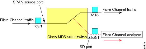
The SPAN feature is specific to switches in the Cisco MDS 9000 Family. It monitors network traffic through a Fibre Channel interface. Traffic through any Fibre Channel interface can be replicated to a special port called the SPAN destination port (SD port). Any Fibre Channel port in a switch can be configured as an SD port. Once an interface is in SD port mode, it cannot be used for normal data traffic. You can attach a Fibre Channel Analyzer to the SD port to monitor SPAN traffic.
SD ports do not receive frames, they only transmit a copy of the SPAN source traffic. The SPAN feature is non-intrusive and does not affect switching of network traffic for any SPAN source ports (see Figure 11-1).
Figure 11-1 SPAN Transmission
SPAN Sources
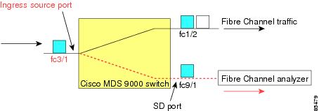
SPAN sources refer to the interfaces from which traffic can be monitored. You can also specify VSAN as a SPAN source, in which case, all supported interfaces in the specified VSAN are included as SPAN sources. When a VSAN as a source is specified, then all physical ports and PortChannels in that VSAN are included as SPAN sources. You can choose the SPAN traffic in the ingress direction, the egress direction, or both directions for any source interface:
•![]() Ingress source (Rx)—Traffic entering the switch fabric through this source interface is spanned or copied to the SD port (see Figure 11-2).
Ingress source (Rx)—Traffic entering the switch fabric through this source interface is spanned or copied to the SD port (see Figure 11-2).
Figure 11-2 SPAN Traffic from the Ingress Direction
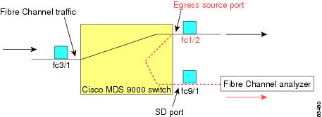
•![]() Egress source (Tx)—Traffic exiting the switch fabric through this source interface is spanned or copied to the SD port (see Figure 11-3).
Egress source (Tx)—Traffic exiting the switch fabric through this source interface is spanned or copied to the SD port (see Figure 11-3).
Figure 11-3 SPAN Traffic from Egress Direction
IPS Source Ports
SPAN capabilities are available on the IP Storage Services (IPS) module. The SPAN feature is only implemented on the FCIP and iSCSI virtual Fibre Channel port interfaces, not the physical Gigabit Ethernet ports. You can configure SPAN for ingress traffic, egress traffic, or traffic in both directions for all eight iSCSI and 24 FCIP interfaces that are available in the IPS module.

Note ![]() You can configure SPAN for Ethernet traffic using Cisco switches or routers connected to the Cisco MDS 9000 Family IPS modules.
You can configure SPAN for Ethernet traffic using Cisco switches or routers connected to the Cisco MDS 9000 Family IPS modules.
Allowed Source Interface Types
The SPAN feature is available for the following interface types:
•![]() Physical ports such as F ports, FL ports, TE ports, E ports, and TL ports.
Physical ports such as F ports, FL ports, TE ports, E ports, and TL ports.
•![]() Interface sup-fc0 (traffic to and from the supervisor):
Interface sup-fc0 (traffic to and from the supervisor):
–![]() The Fibre Channel traffic from the supervisor module to the switch fabric through the sup-fc0 interface is called ingress traffic. It is spanned when sup-fc0 is chosen as an ingress source port.
The Fibre Channel traffic from the supervisor module to the switch fabric through the sup-fc0 interface is called ingress traffic. It is spanned when sup-fc0 is chosen as an ingress source port.
–![]() The Fibre Channel traffic from the switch fabric to the supervisor module through the sup-fc0 interface is called egress traffic. It is spanned when sup-fc0 is chosen as an egress source port.
The Fibre Channel traffic from the switch fabric to the supervisor module through the sup-fc0 interface is called egress traffic. It is spanned when sup-fc0 is chosen as an egress source port.
•![]() PortChannels
PortChannels
–![]() All ports in the PortChannel are included and spanned as sources.
All ports in the PortChannel are included and spanned as sources.
–![]() You cannot specify individual ports in a PortChannel as SPAN sources. Previously configured SPAN-specific interface information is discarded.
You cannot specify individual ports in a PortChannel as SPAN sources. Previously configured SPAN-specific interface information is discarded.
•![]() IPS module specific Fibre Channel interfaces:
IPS module specific Fibre Channel interfaces:
–![]() iSCSI interfaces
iSCSI interfaces
–![]() FCIP interfaces
FCIP interfaces
VSAN as a Source
SPAN sources refer to the interfaces from which traffic can be monitored. When a VSAN as a source is specified, then all physical ports and PortChannels in that VSAN are included as SPAN sources. A TE port is included only when the port VSAN of the TE port matches the source VSAN. A TE port is excluded even if the configured allowed VSAN list may have the source VSAN, but the port VSAN is different.
You cannot configure source interfaces (physical interfaces, PortChannels, or sup-fc interfaces) and source VSANs in the same SPAN session.
Guidelines to Configure VSANs as a Source
The following guidelines apply when configuring VSANs as a source:
•![]() Traffic on all interfaces included in a source VSAN is spanned only in the ingress direction.
Traffic on all interfaces included in a source VSAN is spanned only in the ingress direction.
•![]() If a VSAN is specified as a source, you cannot perform interface-level SPAN configuration on the interfaces that are included in the VSAN. Previously configured SPAN-specific interface information is discarded.
If a VSAN is specified as a source, you cannot perform interface-level SPAN configuration on the interfaces that are included in the VSAN. Previously configured SPAN-specific interface information is discarded.
•![]() If an interface in a VSAN is configured as a source, you cannot configure that VSAN as a source. You must first remove the existing SPAN configurations on such interfaces before configuring VSAN as a source.
If an interface in a VSAN is configured as a source, you cannot configure that VSAN as a source. You must first remove the existing SPAN configurations on such interfaces before configuring VSAN as a source.
•![]() Interfaces are only included as sources when the port VSAN matches the source VSAN. Figure 11-4 displays a configuration using VSAN 2 as a source:
Interfaces are only included as sources when the port VSAN matches the source VSAN. Figure 11-4 displays a configuration using VSAN 2 as a source:
–![]() All ports in the switch are in VSAN 1 except fc1/1.
All ports in the switch are in VSAN 1 except fc1/1.
–![]() Interface fc1/1 is the TE port with port VSAN 2. VSANs 1, 2, and 3 are configured in the allowed list.
Interface fc1/1 is the TE port with port VSAN 2. VSANs 1, 2, and 3 are configured in the allowed list.
–![]() VSAN 1 and VSAN 2 are configured as SPAN sources.
VSAN 1 and VSAN 2 are configured as SPAN sources.
Figure 11-4 VSAN as a Source

For this configuration, the following apply:
–![]() VSAN 2 as a source includes only the TE port fc1/1 that has port VSAN 2.
VSAN 2 as a source includes only the TE port fc1/1 that has port VSAN 2.
–![]() VSAN 1 as a source does not include the TE port fc1/1 because the port VSAN does not match VSAN 1.
VSAN 1 as a source does not include the TE port fc1/1 because the port VSAN does not match VSAN 1.
SPAN Sessions
Each SPAN session represents an association of one destination with a set of source(s) along with various other parameters that you specify to monitor the network traffic. One destination can be used by one or more SPAN sessions. You can configure up to 16 SPAN sessions in a switch. Each session can have several source ports and one destination port.
To activate any SPAN session, at least one source and the SD port must be up and functioning. Otherwise, traffic is not directed to the SD port.

Tip ![]() A source can be shared by two sessions, however, each session must be in a different direction—one ingress and one egress.
A source can be shared by two sessions, however, each session must be in a different direction—one ingress and one egress.
You can temporarily deactivate (suspend) any SPAN session. The traffic monitoring is stopped during this time.
Specifying Filters
You can perform VSAN-based filtering to selectively monitor network traffic on specified VSANs. You can apply this VSAN filter to all sources in a session (see Figure 11-4). Only VSANs present in the filter are spanned.
You can specify session VSAN filters that are applied to all sources in the specified session. These filters are bidirectional and apply to all sources configured in the session. Each SPAN session represents an association of one destination with a set of source(s) along with various other parameters that you specify to monitor the network traffic.
Guidelines to Specifying Filters
The following guidelines apply to SPAN filters:
•![]() PortChannel configurations are applied to all ports in the PortChannel.
PortChannel configurations are applied to all ports in the PortChannel.
•![]() If no filters are specified, the traffic from all active VSANs for that interface is spanned by default.
If no filters are specified, the traffic from all active VSANs for that interface is spanned by default.
•![]() While you can specify arbitrary VSAN filters in a session, traffic can only be monitored on the port VSAN or on allowed-active VSANs in that interface.
While you can specify arbitrary VSAN filters in a session, traffic can only be monitored on the port VSAN or on allowed-active VSANs in that interface.
SD Port Characteristics
An SD port has the following characteristics:
•![]() Ignores BB_credits.
Ignores BB_credits.
•![]() Allows data traffic only in the egress (Tx) direction.
Allows data traffic only in the egress (Tx) direction.
•![]() Does not require a device or an analyzer to be physically connected.
Does not require a device or an analyzer to be physically connected.
•![]() Supports only 1 Gbps or 2 Gbps speeds. The auto speed option is not allowed.
Supports only 1 Gbps or 2 Gbps speeds. The auto speed option is not allowed.
•![]() Multiple sessions can share the same destination ports.
Multiple sessions can share the same destination ports.
•![]() If the SD port is shut down, all shared sessions stop generating SPAN traffic.
If the SD port is shut down, all shared sessions stop generating SPAN traffic.
•![]() The outgoing frames can be encapsulated in Extended Inter-Switch Link (EISL) format.
The outgoing frames can be encapsulated in Extended Inter-Switch Link (EISL) format.
•![]() The SD port does not have a port VSAN.
The SD port does not have a port VSAN.
•![]() SD ports cannot be configured using Storage Services Modules (SSMs).
SD ports cannot be configured using Storage Services Modules (SSMs).
•![]() The port mode cannot be changed if it is being used for a SPAN session.
The port mode cannot be changed if it is being used for a SPAN session.
Note ![]() If you need to change an SD port mode to another port mode, first remove the SD port from all sessions and then change the port mode.
If you need to change an SD port mode to another port mode, first remove the SD port from all sessions and then change the port mode.
Guidelines to Configure SPAN
The following guidelines apply for SPAN configurations:
•![]() You can configure up to 16 SPAN sessions with multiple ingress (Rx) sources.
You can configure up to 16 SPAN sessions with multiple ingress (Rx) sources.
•![]() You can configure a maximum of three SPAN sessions with one egress (Tx) port.
You can configure a maximum of three SPAN sessions with one egress (Tx) port.
•![]() In a 32-port switching module, you must configure the same session in all four ports in one port group (unit). If you wish, you can also configure only two or three ports in this unit.
In a 32-port switching module, you must configure the same session in all four ports in one port group (unit). If you wish, you can also configure only two or three ports in this unit.
•![]() SPAN frames are dropped if the sum of the bandwidth of the sources exceeds the speed of the destination port.
SPAN frames are dropped if the sum of the bandwidth of the sources exceeds the speed of the destination port.
•![]() Frames dropped by a source port are not spanned.
Frames dropped by a source port are not spanned.
Configuring SPAN
To monitor network traffic using SD ports, follow these steps:
Step 1 ![]() Configure the SD port.
Configure the SD port.
Step 2 ![]() Attach the SD port to a specific SPAN session.
Attach the SD port to a specific SPAN session.
Step 3 ![]() Monitor network traffic by adding source interfaces to the session.
Monitor network traffic by adding source interfaces to the session.
Configuring SPAN Using Device Manager
To configure an SD port for SPAN monitoring using Device Manager, follow these steps:
Step 1 ![]() Right-click the port you want to configure and select Configure.
Right-click the port you want to configure and select Configure.
You see the general port configuration dialog.
Step 2 ![]() Under Mode, choose SD.
Under Mode, choose SD.
Step 3 ![]() Click Apply to accept the change.
Click Apply to accept the change.
Step 4 ![]() Close the dialog box.
Close the dialog box.
Configuring SPAN max-queued-packets
When a SPAN destination port is oversubscribed or has more source traffic than the speed of the destination port, the source ports of the SPAN session will reduce in their throughput. The impact is proportional to the amount of source traffic flowing in. Lowering the max-queued-packets value from the default value of 15 to 1 prevents the impact on the source ports. It is necessary to reconsider the default value for this setting as it may impact the source interface throughput.
By default, SPAN frames are dropped if the sum of the bandwidth of the source interfaces exceed the bandwidth of the destination port. With a higher value, the SPAN traffic has a higher probability of reaching the SPAN destination port instead of being dropped at the expense of data traffic throughput.
Note ![]() The span max-queued-packets can be changed only if no SPAN sessions are currently active on the switch.
The span max-queued-packets can be changed only if no SPAN sessions are currently active on the switch.
Note ![]() If you are spanning the traffic going through an FCIP interface, SPAN copies may be dropped even if the SD interface has more bandwidth than the amount of traffic being replicated. To avoid SPAN drops, set the max-queued-packets to a higher value; for example, 100.
If you are spanning the traffic going through an FCIP interface, SPAN copies may be dropped even if the SD interface has more bandwidth than the amount of traffic being replicated. To avoid SPAN drops, set the max-queued-packets to a higher value; for example, 100.
Creating SPAN Sessions
To create SPAN sessions using Device Manager, follow these steps:
Step 1 ![]() Choose Interface > SPAN. You see the SPAN dialog box.
Choose Interface > SPAN. You see the SPAN dialog box.
Step 2 ![]() Click the Sessions tab.
Click the Sessions tab.
Step 3 ![]() Click Create.
Click Create.
You see the Create SPAN Sessions dialog box (see Figure 11-5).
Figure 11-5 Create SPAN Sessions Dialog Box

Step 4 ![]() Choose the session ID (from 1-16) using the up or down arrows and click Create.
Choose the session ID (from 1-16) using the up or down arrows and click Create.
Step 5 ![]() Repeat Step 4 for each session you want to create.
Repeat Step 4 for each session you want to create.
Step 6 ![]() Enter the destination interface in the Dest Interface field for the appropriate session.
Enter the destination interface in the Dest Interface field for the appropriate session.
Step 7 ![]() Enter the filter VSAN list in the Filter VSAN List field for the appropriate session.
Enter the filter VSAN list in the Filter VSAN List field for the appropriate session.
Step 8 ![]() Choose active or in active admin status in the Admin drop-down list.
Choose active or in active admin status in the Admin drop-down list.
Step 9 ![]() Click Apply to save your changes.
Click Apply to save your changes.
Step 10 ![]() Close the two dialog boxes.
Close the two dialog boxes.
Configuring SPAN for Generation 2 Fabric Switches
Cisco Generation 2 fabric switches (such as MDS 9124) support SPAN sessions in both directions, Rx and Tx.
Note ![]() While using Generation 2 fabric switches, you cannot create an additional active SPAN session when you already have one.
While using Generation 2 fabric switches, you cannot create an additional active SPAN session when you already have one.
You can specify multiple SPAN source interfaces in Rx and Tx directions. You cannot mix ingress and egress interfaces in the same SPAN session. The SPAN will reject any configuration that mixes Rx ad Tx directions. However, you can specify multiple SPAN source interfaces in a single direction.
Generation 2 Fabric Switches support VSAN filters for one VSAN only in the egress direction; this restriction does not apply to the ingress direction. For example, if you have an interface that is a TE port, with an active VSAN of 1 to 5, and you specify a VSAN filter for VSAN 2, then only the traffic on VSAN 2 will be filtered.
Editing SPAN Sources
To edit a SPAN source using Device Manager, follow these steps:
Step 1 ![]() Choose Interface > SPAN.
Choose Interface > SPAN.
You see the SPAN dialog box.
Step 2 ![]() Click the Sources tab.
Click the Sources tab.
You see the dialog box (see Figure 11-6).
Figure 11-6 SPAN Sources Tab

Step 3 ![]() Enter the VSAN list name in the VSAN List field.
Enter the VSAN list name in the VSAN List field.
Step 4 ![]() Click Edit Interface List.
Click Edit Interface List.
You see the Source Interfaces dialog box.
Step 5 ![]() Click Create.
Click Create.
You see the Source Interfaces Interface Sources dialog box (see Figure 11-7).
Figure 11-7 Source Interfaces Interface Sources Dialog Box

Step 6 ![]() Click the browse button to display the list of available FC ports.
Click the browse button to display the list of available FC ports.
Step 7 ![]() Choose a port and click OK.
Choose a port and click OK.
Step 8 ![]() Click the direction (receive or transmit) you want.
Click the direction (receive or transmit) you want.
Step 9 ![]() Click Create to create the FC interface source.
Click Create to create the FC interface source.
Step 10 ![]() Click Close in each of the three open dialog boxes.
Click Close in each of the three open dialog boxes.
Deleting SPAN Sessions
To delete a SPAN session using Device Manager, follow these steps:
Step 1 ![]() Choose Interface > SPAN.
Choose Interface > SPAN.
You see the SPAN dialog box.
Step 2 ![]() Click the Sessions tab.
Click the Sessions tab.
Step 3 ![]() Click the SPAN session you want to delete.
Click the SPAN session you want to delete.
Step 4 ![]() Click Delete.
Click Delete.
The SPAN session is deleted.
Step 5 ![]() Close the dialog box.
Close the dialog box.
SPAN Conversion Behavior
SPAN features (configured in any prior release) are converted as follows:
•![]() If source interfaces and source VSANs are configured in a given session, then all the source VSANs are removed from that session.
If source interfaces and source VSANs are configured in a given session, then all the source VSANs are removed from that session.
For example, before Cisco MDS SAN-OS Release 1.0(4):
Session 1 (active)
Destination is fc1/9
No session filters configured
Ingress (rx) sources are
vsans 10-11
fc1/3,
Egress (tx) sources are
fc1/3,
Once upgraded to Cisco MDS SAN-OS Release 1.1(1):
Session 1 (active)
Destination is fc1/9
No session filters configured
Ingress (rx) sources are
fc1/3,
Egress (tx) sources are
fc1/3,
Session 1 had both source interfaces and source VSANs before the upgrade. After the upgrade, the source VSANs were removed (rule 1).
•![]() If interface level VSAN filters are configured in source interfaces, then the source interfaces are also removed from the session. If this interface is configured in both directions, it is removed from both directions.
If interface level VSAN filters are configured in source interfaces, then the source interfaces are also removed from the session. If this interface is configured in both directions, it is removed from both directions.
For example, before Cisco MDS SAN-OS Release 1.0(4):
Session 2 (active)
Destination is fc1/9
No session filters configured
Ingress (rx) sources are
vsans 12
fc1/6 (vsan 1-20),
Egress (tx) sources are
fc1/6 (vsan 1-20),
Once upgraded to Cisco MDS SAN-OS Release 1.1(1):
Session 2 (inactive as no active sources)
Destination is fc1/9
No session filters configured
No ingress (rx) sources
No egress (tx) sources
Note ![]() The deprecated configurations are removed from persistent memory once a switchover or a new startup configuration is implemented.
The deprecated configurations are removed from persistent memory once a switchover or a new startup configuration is implemented.
Session 2 had a source VSAN 12 and a source interface fc1/6 with VSAN filters specified in Cisco MDS SAN-OS Release 1.0(4). When upgraded to Cisco MDS SAN-OS Release 1.1(1) the following changes are made:
–![]() The source VSAN (VSAN 12) is removed (rule 1).
The source VSAN (VSAN 12) is removed (rule 1).
–![]() The source interface fc1/6 had VSAN filters specified—it is also removed (rule 2).
The source interface fc1/6 had VSAN filters specified—it is also removed (rule 2).
Monitoring Traffic Using Fibre Channel Analyzers
You can use SPAN to monitor traffic on an interface without any traffic disruption. This feature is especially useful in troubleshooting scenarios in which traffic disruption changes the problem environment and makes it difficult to reproduce the problem. You can monitor traffic in either of the following two ways:
•![]() Without SPAN
Without SPAN
•![]() With SPAN
With SPAN
Without SPAN
You can monitor traffic using interface fc1/1 in a Cisco MDS 9000 Family switch that is connected to another switch or host. You need to physically connect a Fibre Channel analyzer between the switch and the storage device to analyze the traffic through interface fc1/1 (see Figure 11-8).
Figure 11-8 Fibre Channel Analyzer Usage Without SPAN

This type of connection has the following limitations:
•![]() It requires you to physically insert the FC analyzer between the two network devices.
It requires you to physically insert the FC analyzer between the two network devices.
•![]() It disrupts traffic when the Fibre Channel analyzer is physically connected.
It disrupts traffic when the Fibre Channel analyzer is physically connected.
•![]() The analyzer captures data only on the Rx links in both port 1 and port 2. Port 1 captures traffic exiting interface fc1/1 and port 2 captures ingress traffic into interface fc1/1.
The analyzer captures data only on the Rx links in both port 1 and port 2. Port 1 captures traffic exiting interface fc1/1 and port 2 captures ingress traffic into interface fc1/1.
With SPAN
Using SPAN you can capture the same traffic scenario (see Figure 11-8) without any traffic disruption. The Fibre Channel analyzer uses the ingress (Rx) link at port 1 to capture all the frames going out of the interface fc1/1. It uses the ingress link at port 2 to capture all the ingress traffic on interface fc1/1.
Using SPAN you can monitor ingress traffic on fc1/1 at SD port fc2/2 and egress traffic on SD port fc2/1. This traffic is seamlessly captured by the FC analyzer (see Figure 11-9).
Figure 11-9 Fibre Channel Analyzer Using SPAN
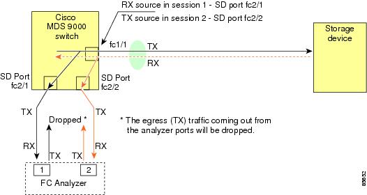
Configuring Fibre Channel Analyzers Using SPAN
To configure Fibre Channel Analyzers using SPAN for the example in Figure 11-9, follow these steps:
Step 1 ![]() Configure SPAN on interface fc1/1 in the ingress (Rx) direction to send traffic on SD port fc2/1 using session 1.
Configure SPAN on interface fc1/1 in the ingress (Rx) direction to send traffic on SD port fc2/1 using session 1.
Step 2 ![]() Configure SPAN on interface fc1/1in the egress (Tx) direction to send traffic on SD port fc2/2 using session 2.
Configure SPAN on interface fc1/1in the egress (Tx) direction to send traffic on SD port fc2/2 using session 2.
Step 3 ![]() Physically connect fc2/1 to port 1 on the Fibre Channel analyzer.
Physically connect fc2/1 to port 1 on the Fibre Channel analyzer.
Step 4 ![]() Physically connect fc2/2 to port 2 on the Fibre Channel analyzer.
Physically connect fc2/2 to port 2 on the Fibre Channel analyzer.
Single SD Port to Monitor Traffic
You do not need to use two SD ports to monitor bidirectional traffic on any interface (see Figure 11-9). You can use one SD port and one FC analyzer port by monitoring traffic on the interface at the same SD port fc2/1.
Figure 11-10 shows a SPAN setup where one session with destination port fc2/1 and source interface fc1/1 is used to capture traffic in both ingress and egress directions. This setup is more advantageous and cost effective than the setup shown in Figure 11-9—it uses one SD port and one port on the analyzer, instead of using a full, two-port analyzer.
Figure 11-10 Fibre Channel Analyzer Using a Single SD Port
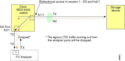
To use this setup, the analyzer should have the capability of distinguishing ingress and egress traffic for all captured frames.
Remote SPAN
Note ![]() Remote SPAN is not supported on the Cisco Fabric Switch for HP c-Class BladeSystem and the Cisco Fabric Switch for IBM BladeSystem.
Remote SPAN is not supported on the Cisco Fabric Switch for HP c-Class BladeSystem and the Cisco Fabric Switch for IBM BladeSystem.
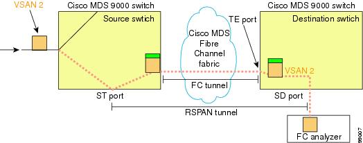
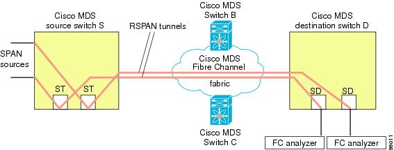
The Remote SPAN (RSPAN) feature enables you to remotely monitor traffic for one or more SPAN sources distributed in one or more source switches in a Fibre Channel fabric. The SPAN destination (SD) port is used for remote monitoring in a destination switch. A destination switch is usually different from the source switch(es) but is attached to the same Fibre Channel fabric. You can replicate and monitor traffic in any remote Cisco MDS 9000 Family switch or director, just as you would monitor traffic in a Cisco MDS source switch.
The RSPAN feature is nonintrusive and does not affect network traffic switching for those SPAN source ports. Traffic captured on the remote switch is tunneled across a Fibre Channel fabric which has trunking enabled on all switches in the path from the source switch to the destination switch. The Fibre Channel tunnel is structured using trunked ISL (TE) ports. In addition to TE ports, the RSPAN feature uses two other interface types (see Figure 11-11):
•![]() SD ports—A passive port from which remote SPAN traffic can be obtained by the FC analyzer.
SD ports—A passive port from which remote SPAN traffic can be obtained by the FC analyzer.
•![]() ST ports—A SPAN tunnel (ST) port is an entry point port in the source switch for the RSPAN Fibre Channel tunnel. ST ports are special RSPAN ports and cannot be used for normal Fibre Channel traffic.
ST ports—A SPAN tunnel (ST) port is an entry point port in the source switch for the RSPAN Fibre Channel tunnel. ST ports are special RSPAN ports and cannot be used for normal Fibre Channel traffic.
Figure 11-11 RSPAN Transmission

Advantages to Using RSPAN
The RSPAN features has the following advantages:
•![]() Enables nondisruptive traffic monitoring at a remote location.
Enables nondisruptive traffic monitoring at a remote location.
•![]() Provides a cost effective solution by using one SD port to monitor remote traffic on multiple switches.
Provides a cost effective solution by using one SD port to monitor remote traffic on multiple switches.
•![]() Works with any Fibre Channel analyzer.
Works with any Fibre Channel analyzer.
•![]() Is compatible with the Cisco MDS 9000 Port Analyzer adapters.
Is compatible with the Cisco MDS 9000 Port Analyzer adapters.
•![]() Does not affect traffic in the source switch, but shares the ISL bandwidth with other ports in the fabric.
Does not affect traffic in the source switch, but shares the ISL bandwidth with other ports in the fabric.
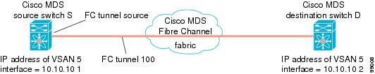
FC and RSPAN Tunnels
An FC tunnel is a logical data path between a source switch and a destination switch. The FC tunnel originates from the source switch and terminates at the remotely located destination switch.
RSPAN uses a special Fibre Channel tunnel (FC tunnel) that originates at the ST port in the source switch and terminates at the SD port in the destination switch. You must bind the FC tunnel to an ST port in the source switch and map the same FC tunnel to an SD port in the destination switch. Once the mapping and binding is configured, the FC tunnel is referred to as an RSPAN tunnel (see Figure 11-12).
Figure 11-12 FC and RSPAN Tunnel
RSPAN Configuration Guidelines
The following guidelines apply for a SPAN configuration:
•![]() All switches in the end-to-end path of the RSPAN tunnel must belong to the Cisco MDS 9000 Family.
All switches in the end-to-end path of the RSPAN tunnel must belong to the Cisco MDS 9000 Family.
•![]() All VSANs with RSPAN traffic must be enabled. If a VSAN containing RSPAN traffic is not enabled, it is dropped.
All VSANs with RSPAN traffic must be enabled. If a VSAN containing RSPAN traffic is not enabled, it is dropped.
•![]() The following configurations must be performed on each switch in the end-to-end path of the Fibre Channel tunnel in which RSPAN is to be implemented:
The following configurations must be performed on each switch in the end-to-end path of the Fibre Channel tunnel in which RSPAN is to be implemented:
–![]() Trunking must be enabled (enabled by default) and the trunk enabled link must be the lowest cost link in the path.
Trunking must be enabled (enabled by default) and the trunk enabled link must be the lowest cost link in the path.
–![]() VSAN interface must be configured.
VSAN interface must be configured.
–![]() The Fibre Channel tunnel feature must be enabled (disabled by default).
The Fibre Channel tunnel feature must be enabled (disabled by default).
–![]() IP routing must be enabled (disabled by default).
IP routing must be enabled (disabled by default).
Note ![]() If the IP address is in the same subnet as the VSAN, the VSAN interface does not have to be configured for all VSANs on which the traffic is spanned.
If the IP address is in the same subnet as the VSAN, the VSAN interface does not have to be configured for all VSANs on which the traffic is spanned.
•![]() A single Fibre Channel switch port must be dedicated for the ST port functionality.
A single Fibre Channel switch port must be dedicated for the ST port functionality.
•![]() Do not configure the port to be monitored as the ST port.
Do not configure the port to be monitored as the ST port.
•![]() The FC tunnel's IP address must reside in the same subnet as the VSAN interface.
The FC tunnel's IP address must reside in the same subnet as the VSAN interface.
ST Port Characteristics
ST ports have the following characteristics:
•![]() ST ports perform the RSPAN encapsulation of the FC frame.
ST ports perform the RSPAN encapsulation of the FC frame.
•![]() ST ports do not use BB_credits.
ST ports do not use BB_credits.
•![]() One ST port can only be bound to one FC tunnel.
One ST port can only be bound to one FC tunnel.
•![]() ST ports cannot be used for any purpose other than to carry RSPAN traffic.
ST ports cannot be used for any purpose other than to carry RSPAN traffic.
•![]() ST ports cannot be configured using Storage Services Modules (SSMs).
ST ports cannot be configured using Storage Services Modules (SSMs).
Configuring RSPAN
The RSPAN tunnel begins in the source switch and terminates in the destination switch. This section assumes Switch S to be the source and Switch D to be the destination.
Note ![]() Besides the source and destination switches, the VSAN must also be configured in each Cisco MDS switch in the Fibre Channel fabric, if they exist.
Besides the source and destination switches, the VSAN must also be configured in each Cisco MDS switch in the Fibre Channel fabric, if they exist.
To monitor network traffic using the RSPAN feature, follow these steps:
Step 1 ![]() Create VSAN interfaces in destination switch (Switch D) and source switch (Switch S) to facilitate the Fibre Channel tunnel (FC tunnel) creation.
Create VSAN interfaces in destination switch (Switch D) and source switch (Switch S) to facilitate the Fibre Channel tunnel (FC tunnel) creation.
Step 2 ![]() Enable the FC tunnel in each switch in the end-to-end path of the tunnel.
Enable the FC tunnel in each switch in the end-to-end path of the tunnel.
Step 3 ![]() Initiate the FC tunnel (in Switch S) and map the tunnel to the VSAN interface's IP address (in Switch D) so all RSPAN traffic from the tunnel is directed to the SD port.
Initiate the FC tunnel (in Switch S) and map the tunnel to the VSAN interface's IP address (in Switch D) so all RSPAN traffic from the tunnel is directed to the SD port.
Step 4 ![]() Configure SD ports for SPAN monitoring in the destination switch (Switch D).
Configure SD ports for SPAN monitoring in the destination switch (Switch D).
Step 5 ![]() Configure the ST port in the source switch (Switch S) and bind the ST port to the FC tunnel.
Configure the ST port in the source switch (Switch S) and bind the ST port to the FC tunnel.
Step 6 ![]() Create an RSPAN session in the source switch (in Switch S) to monitor network traffic.
Create an RSPAN session in the source switch (in Switch S) to monitor network traffic.
Creating VSAN Interfaces
Figure 11-13 depicts a basic FC tunnel configuration.
Figure 11-13 FC Tunnel Configuration
Note ![]() This example assumes that VSAN 5 is already configured in the VSAN database.
This example assumes that VSAN 5 is already configured in the VSAN database.
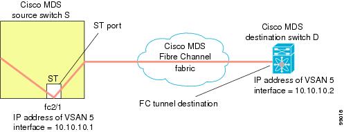
Configuring the ST Port
Once the FC tunnel is created, be sure to configure the ST port to bind it to the FC tunnel at the source switch. The FC tunnel becomes an RSPAN tunnel once the binding and mapping is complete.
Figure 11-14 depicts a basic FC tunnel configuration.
Figure 11-14 Binding the FC Tunnel

Note ![]() ST ports cannot be configured using Storage Services Modules (SSMs).
ST ports cannot be configured using Storage Services Modules (SSMs).
Configuring the SD Port
The SD port in the destination switch enables the FC analyzer to receive the RSPAN traffic from the Fibre Channel tunnel. Figure 11-15 depicts an RSPAN tunnel configuration, now that tunnel destination is also configured.
Figure 11-15 RSPAN Tunnel Configuration

Note ![]() SD ports cannot be configured using Storage Services Modules (SSMs).
SD ports cannot be configured using Storage Services Modules (SSMs).
Mapping the FC Tunnel
The tunnel-id-map option specifies the egress interface of the tunnel at the destination switch (see Figure 11-16).
Figure 11-16 FC Tunnel Configuration
Explicit Paths
You can specify an explicit path through the Cisco MDS Fibre Channel fabric (source-based routing), using the explicit-path option. For example, if you have multiple paths to a tunnel destination, you can use this option to specify the FC tunnel to always take one path to the destination switch. The software then uses this specified path even if other paths are available.
This option is especially useful if you prefer to direct the traffic through a certain path although other paths are available. In an RSPAN situation, you can specify the explicit path so the RSPAN traffic does not interfere with the existing user traffic. You can create any number of explicit paths in a switch (see Figure 11-17).
Figure 11-17 Explicit Path Configuration

The explicit path must be created in the source switch. To configure an explicit path, you must first create the path and then configure the use of any one path. If an explicit path is not configured, the minimum cost path is used by default. If an explicit path is configured and is functioning, the specified path is used.
Monitoring RSPAN Traffic
Once the session is configured, other SPAN sources for this session can also be configured as required. Figure 11-18 shows an RSPAN setup where one session with destination port fc2/1 and source interface fc1/1 is used to capture traffic in both ingress and egress directions.
Figure 11-18 Fibre Channel Analyzer Using a Single SD Port to Monitor RSPAN Traffic

To use this setup, the analyzer should have the capability of distinguishing ingress and egress traffic for all captured frames.
Sample Scenarios
Note ![]() RSPAN can be combined with the local SPAN feature so SD ports forward local SPAN traffic along with remote SPAN traffic. Various SPAN source and tunnel scenarios are described in this section.
RSPAN can be combined with the local SPAN feature so SD ports forward local SPAN traffic along with remote SPAN traffic. Various SPAN source and tunnel scenarios are described in this section.
Single Source with One RSPAN Tunnel
The source Switch S and the destination Switch D are interconnected through a Fibre Channel fabric. An RSPAN tunnel is configured as a destination interface for the SPAN session and the ST port forwards SPAN traffic through the RSPAN tunnel (see Figure 11-19).
Figure 11-19 RSPAN Scenario with One Source Switch, One Destination Switch, and One Tunnel

Single Source with Multiple RSPAN Tunnels
Figure 11-20 displays two separate RSPAN tunnels configured between Switches S and N. Each tunnel has an associated ST port in the source switch and a separate SD port in the destination switch. This configuration is useful for troubleshooting purposes.
Figure 11-20 RSPAN Scenario with One Source Switch, One Destination Switch, and Multiple Tunnels
Multiple Sources with Multiple RSPAN Tunnels
Figure 11-21 displays two separate RSPAN tunnels configured between Switches S1 and S2. Both tunnels have an associated ST port in their respective source switch and terminate in the same SD port in the destination switch.
Figure 11-21 RSPAN Scenario with Two Source Switches, a Destination Switch, and Multiple Tunnels

This configuration is useful for remote monitoring purposes. For example, the administrator may be at the destination switch and can remotely monitor the two source switches.
Default SPAN and RSPAN Settings
Table 11-1 lists the default settings for SPAN parameters.
 Feedback