- New and Changed Information
- Preface
- Overview
- Using the CFS Infrastructure
- Configuring System Message Logging
- Configuring Callhome
- Scheduling Maintenance Jobs
- Monitoring System Processes and Log
- Configuring Embeddded Event Manager
- Configuring RMON
- Configuring Generic Online Diagnostics
- Configuring SNMP
- Configuring Domain Parameters
- Monitoring Network Traffic Using SPAN
- Configuring Fabric Configuration Servers
- Configuring Port Pacer
Cisco MDS 9000 Family NX-OS System Management Configuration Guide
Bias-Free Language
The documentation set for this product strives to use bias-free language. For the purposes of this documentation set, bias-free is defined as language that does not imply discrimination based on age, disability, gender, racial identity, ethnic identity, sexual orientation, socioeconomic status, and intersectionality. Exceptions may be present in the documentation due to language that is hardcoded in the user interfaces of the product software, language used based on RFP documentation, or language that is used by a referenced third-party product. Learn more about how Cisco is using Inclusive Language.
- Updated:
- July 15, 2014
Chapter: Using the CFS Infrastructure
- Information About CFS
- Guidelines and Limitations
- Default Settings
- Configuring CFS
- Configuring CFS Regions
- Verifying CFS Configurations
- Additional References
- Feature History for CFS
Using the CFS Infrastructure
Cisco Fabric Services (CFS) provides a common infrastructure for automatic configuration synchronization in the fabric. It provides the transport function as well as a rich set of common services to the applications. CFS has the ability to discover CFS-capable switches in the fabric and discover application capabilities in all CFS-capable switches.
Information About CFS
The Cisco MDS NX-OS software uses the Cisco Fabric Services (CFS) infrastructure to enable efficient database distribution and to foster device flexibility. It simplifies SAN provisioning by automatically distributing configuration information to all switches in a fabric.
Several Cisco MDS NX-OS applications use the CFS infrastructure to maintain and distribute the contents of a particular application’s database.
Many features in the Cisco MDS switches require configuration synchronization in all switches in the fabric. Maintaining configuration synchronization across a fabric is important to maintain fabric consistency. In the absence of a common infrastructure, such synchronization is achieved through manual configuration at each switch in the fabric. This process is tedious and error prone.
This section includes the following topics:
- Cisco MDS NX-OS Features Using CFS
- CFS Features
- Enabling CFS for an Application
- CFS Protocol
- CFS Distribution Scopes
- CFS Distribution Modes
- Locking the Fabric
- Committing Changes
- CFS Merge Support
- CFS Distribution over IP
- Static IP Peers for CFS
- About CFS Regions
Cisco MDS NX-OS Features Using CFS
The following Cisco NX-OS features use the CFS infrastructure:
- N Port Virtualization
- FlexAttach Virtual pWWN
- NTP
- Dynamic Port VSAN Membership
- Distributed Device Alias Services
- IVR topology
- SAN device virtualization
- TACACS+ and RADIUS
- User and administrator roles
- Port security
- iSNS
- Call Home
- Syslog
- fctimer
- SCSI flow services
- Saved startup configurations using the Fabric Startup Configuration Manager (FSCM)
- Allowed domain ID lists
- RSCN timer
- iSLB
CFS Features
CFS has the following features:
- Peer-to-peer protocol with no client-server relationship at the CFS layer.
- Three scopes of distribution.
–![]() Logical scope—The distribution occurs within the scope of a VSAN.
Logical scope—The distribution occurs within the scope of a VSAN.
–![]() Physical scope—The distribution spans the entire physical topology.
Physical scope—The distribution spans the entire physical topology.
–![]() Over a selected set of VSANs—Some applications, such as Inter-VSAN Routing (IVR), require configuration distribution over some specific VSANs. These applications can specify to CFS the set of VSANs over which to restrict the distribution.
Over a selected set of VSANs—Some applications, such as Inter-VSAN Routing (IVR), require configuration distribution over some specific VSANs. These applications can specify to CFS the set of VSANs over which to restrict the distribution.
–![]() Coordinated distributions—Only one distribution is allowed in the fabric at any given time.
Coordinated distributions—Only one distribution is allowed in the fabric at any given time.
–![]() Uncoordinated distributions—Multiple parallel distributions are allowed in the fabric except when a coordinated distribution is in progress.
Uncoordinated distributions—Multiple parallel distributions are allowed in the fabric except when a coordinated distribution is in progress.
–![]() Unrestricted uncoordinated distributions—Multiple parallel distributions are allowed in the fabric in the presence of an existing coordinated distribution. Unrestricted uncoordinated distributions are allowed to run in parallel with all other types of distributions.
Unrestricted uncoordinated distributions—Multiple parallel distributions are allowed in the fabric in the presence of an existing coordinated distribution. Unrestricted uncoordinated distributions are allowed to run in parallel with all other types of distributions.
Enabling CFS for an Application
All CFS-based applications provide an option to enable or disable the distribution capabilities. Features that existed prior to Cisco SAN-OS Release 2.0(1b) have the distribution capability disabled by default and must have distribution capabilities enabled explicitly.
Applications introduced in Cisco SAN-OS Release 2.0(1b) or later, or MDS NX-OS Release 4.1(1) or later have the distribution enabled by default.
The application configuration is not distributed by CFS unless distribution is explicitly enabled for that application.
CFS Protocol
The CFS functionality is independent of the lower layer transport. Currently, in Cisco MDS switches, the CFS protocol layer resides on top of the Fiber Channel 2 (FC2) layer and is peer-to-peer with no client-server relationship. CFS uses the FC2 transport services to send information to other switches. CFS uses a proprietary SW_ILS (0x77434653) protocol for all CFS packets. CFS packets are sent to or from the switch domain controller addresses.
CFS can also use IP to send information to other switches.
Applications that use CFS are completely unaware of the lower layer transport.
CFS Distribution Scopes
Different applications on the Cisco MDS 9000 Family switches need to distribute the configuration at various levels:
Applications that operate within the scope of a VSAN have the configuration distribution restricted to the VSAN. An example application is port security where the configuration database is applicable only within a VSAN.
Applications might need to distribute the configuration to the entire physical topology spanning several VSANs. Such applications include NTP and DPVM (WWN-based VSAN), which are independent of VSANs.
Applications might only operate between selected switches in the fabric. An example application is SCSI flow services, which operates between two switches.
CFS Distribution Modes
CFS supports different distribution modes to support different application requirements: coordinated and uncoordinated distributions. Both modes are mutually exclusive. Only one mode is allowed at any given time.
Uncoordinated Distribution
Uncoordinated distributions are used to distribute information that is not expected to conflict with that from a peer. An example is local device registrations such as iSNS. Parallel uncoordinated distributions are allowed for an application.
Coordinated Distribution
Coordinated distributions can have only one application distribution at a given time. CFS uses locks to enforce this. A coordinated distribution is not allowed to start if locks are taken for the application anywhere in the fabric. A coordinated distribution consists of three stages:
2.![]() The configuration is distributed and committed.
The configuration is distributed and committed.
3.![]() The fabric lock is released.
The fabric lock is released.
Coordinated distribution has two variants:
- CFS driven —The stages are executed by CFS in response to an application request without intervention from the application.
- Application driven—The stages are under the complete control of the application.
Coordinated distributions are used to distribute information that can be manipulated and distributed from multiple switches, for example, the port security configuration.
Unrestricted Uncoordinated Distributions
Unrestricted uncoordinated distributions allow multiple parallel distributions in the fabric in the presence of an existing coordinated distribution. Unrestricted uncoordinated distributions are allowed to run in parallel with all other types of distributions.
CFS Connectivity in a Mixed Fabric
CFS is an infrastructure component that also runs on the Cisco Nexus 5000 Series switches and the Cisco MDS 9000 switches. A mixed fabric of different platforms (such as the Cisco Nexus 7000 Series, Cisco Nexus 5000 Series, and Cisco MDS 9000 switches) can interact with each other.
Using CFSoIP and CFSoFC, the respective CFS clients can also talk to their instances running on the other platforms. Within a defined domain and distribution scope, CFS can distribute the client’s data and configuration to its peers running on other platforms.
All three platforms support both CFSoIP and CFSoFC. However, the Cisco Nexus 7000 Series and Cisco Nexus 5000 Series switches require an FC or FCoE plugin and corresponding configuration in order for CFSoFC to operate. Both options are available by default on the Cisco MDS 9000 switches.

Note![]() Some applications are not compatible with their instances running on different platforms. Therefore, Cisco recommends that you carefully read the client guidelines for CFS distribution before committing the configuration.
Some applications are not compatible with their instances running on different platforms. Therefore, Cisco recommends that you carefully read the client guidelines for CFS distribution before committing the configuration.
For more information on CFS for the Cisco Nexus 5000 Series and Cisco MDS 9000 switches, see the Cisco Nexus 5000 Series NX-OS System Management Configuration Guide and the Cisco MDS 9000 Family NX-OS System Management Configuration Guide, respectively.
Locking the Fabric
When you configure (first time configuration) a Cisco NX-OS feature (or application) that uses the CFS infrastructure, that feature starts a CFS session and locks the fabric. When a fabric is locked, the Cisco NX-OS software does not allow any configuration changes from a switch to this Cisco NX-OS feature, other than the switch holding the lock, and issues a message to inform the user about the locked status. The configuration changes are held in a pending database by that application.
If you start a CFS session that requires a fabric lock but forget to end the session, an administrator can clear the session. If you lock a fabric at any time, your user name is remembered across restarts and switchovers. If another user (on the same machine) tries to perform configuration tasks, that user’s attempts are rejected.
For information on verifying CFS lock status, refer to “Verifying CFS Lock Status” section.
Committing Changes
A commit operation saves the pending database for all application peers and releases the lock for all switches.
In general, the commit function does not start a session; only a lock function starts a session. However, an empty commit is allowed if configuration changes are not previously made. In this case, a commit operation results in a session that acquires locks and distributes the current database.
When you commit configuration changes to a feature using the CFS infrastructure, you receive a notification about one of the following responses:
- One or more external switches report a successful status—The application applies the changes locally and releases the fabric lock.
- None of the external switches report a successful state—The application considers this state a failure and does not apply the changes to any switch in the fabric. The fabric lock is not released.
Note![]() Once the "feature commit" is done the running configuration has been modified on all switches participating in the feature's distribution. You can then use the "copy running-config startup-config fabric" command to save the running-config to the startup-config on all the switches in the fabric.
Once the "feature commit" is done the running configuration has been modified on all switches participating in the feature's distribution. You can then use the "copy running-config startup-config fabric" command to save the running-config to the startup-config on all the switches in the fabric.
CFS Merge Support
An application keeps the configuration synchronized in a fabric through CFS. Two such fabrics might merge as a result of an ISL coming up between them. These two fabrics could have two different sets of configuration information that need to be reconciled in the event of a merge. CFS provides notification each time an application peer comes online. If a fabric with M application peers merges with another fabric with N application peers and if an application triggers a merge action on every such notification, a link-up event results in M*N merges in the fabric.
CFS supports a protocol that reduces the number of merges required to one by handling the complexity of the merge at the CFS layer. This protocol runs per application per scope. The protocol involves selecting one switch in a fabric as the merge manager for that fabric. The other switches do not play any role in the merge process.
During a merge, the merge manager in the two fabrics exchange their configuration databases with each other. The application on one of them merges the information, decides if the merge is successful, and informs all switches in the combined fabric of the status of the merge.
In case of a successful merge, the merged database is distributed to all switches in the combined fabric and the entire new fabric remains in a consistent state.
CFS Distribution over IP
You can configure CFS to distribute information over IP for networks containing switches that are not reachable over Fibre Channel. CFS distribution over IP supports the following features:
- Physical distribution over an entirely IP network.
- Physical distribution over a hybrid Fibre Channel and IP network with the distribution reaching all switches that are reachable over either Fibre Channel or IP.
Note![]() The switch attempts to distribute information over Fibre Channel first and then over the IP network if the first attempt over Fibre Channel fails. CFS does not send duplicate messages if distribution over both IP and Fibre Channel is enabled.
The switch attempts to distribute information over Fibre Channel first and then over the IP network if the first attempt over Fibre Channel fails. CFS does not send duplicate messages if distribution over both IP and Fibre Channel is enabled.
Note![]() CFS cannot distribute over both IPv4 and IPv6 from the same switch.
CFS cannot distribute over both IPv4 and IPv6 from the same switch.
- Keepalive mechanism to detect network topology changes using a configurable multicast address.
- Compatibility with Cisco MDS SAN-OS Release 2.x.
- Distribution for logical scope applications is not supported because the VSAN implementation is limited to Fibre Channel.
Figure 2-1 shows a network with both Fibre Channel and IP connections. Node A forwards an event to node B over Fibre Channel. Node B forwards the event node C and node D using unicast IP. Node C forwards the event to node E using Fibre Channel.
Figure 2-1 Network Example 1 with Fibre Channel and IP Connections
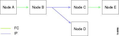
Figure 2-2 is the same as Figure 2-1 except that node D and node E are connected using Fibre Channel. All processes is the same in this example because node B has node C and node D the distribution list for IP. Node C does not forward to node D because node D is already in the distribution list from node B.
Figure 2-2 Network Example 2 with Fibre Channel and IP Connections
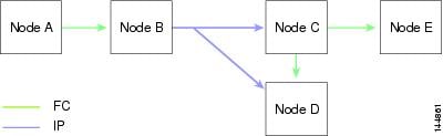
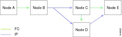
Figure 2-3 is the same as Figure 2-2 except that node D and node E are connected using IP. Both node C and node D forward the event to E because the node E is not in the distribution list from node B.
Figure 2-3 Network Example 3 with Fibre Channel and IP Connections
Static IP Peers for CFS
CFS over IP can also be used with static IP peers. In this case, dynamic discovery over IP multicast is disabled and CFS distribution is done only on the peers configured statically.
CFS uses the list of configured IP addresses to communicate with each peer and learn the peer switch WWN. After learning the peer switch WWN, CFS marks the switch as CFS-capable and triggers application-level merging and database distribution.
Multicast forwarding is disabled by default in some devices. For example, the IBM Blade chassis has multicast forwarding disabled, especially on external Ethernet ports, and there is no method to enable it. N port virtualization devices use only IP as the transport medium and do not have ISL connectivity or a Fibre Channel domain. Such devices may benefit from using static IP peers for CFS.
The following MDS 9000 features require static IP peer configuration for CFS over IP distribution:
About CFS Regions
A CFS region is a user-defined subset of switches for a given feature or application in its physical distribution scope.When a SAN is spanned across a vast geography, you may need to localize or restrict the distribution of certain profiles among a set of switches based on their physical proximity. Before MDS SAN-OS Release 3.2.(1) the distribution scope of an application within a SAN was spanned across the entire physical fabric without the ability to confine or limit the distribution to a required set of switches in the fabric. CFS regions enables you to overcome this limitation by allowing you to create CFS regions, that is, multiple islands of distribution within the fabric, for a given CFS feature or application. CFS regions are designed to restrict the distribution of a feature’s configuration to a specific set or grouping of switches in a fabric.
Note![]() You can only configure a CFS region on physical switches in a SAN. You cannot configure a CFS region in a VSAN.
You can only configure a CFS region on physical switches in a SAN. You cannot configure a CFS region in a VSAN.
Example CFS Scenario : Call Home is an application that triggers alerts to Network Administrators when a situation arises or something abnormal occurs. When the fabric covers many geographies and with multiple Network Administrators who are each responsible for a subset of switches in the fabric, the Call Home application sends alerts to all Network Administrators regardless of their location. For the Call Home application to send message alerts selectively to Network Administrators, the physical scope of the application has to be fine tuned or narrowed down, which is achieved by implementing CFS regions.
CFS regions are identified by numbers ranging from 0 through 200. Region 0 is reserved as the default region, and contains every switch in the fabric. You can configure regions from 1 through 200. The default region maintains backward compatibility. If there are switches on the same fabric running releases of SAN-OS before Release 3.2(1), only features in Region 0 are supported when those switches are synchronized. Features from other regions are ignored when those switches are synchronized.
If the feature is moved, that is, assigned to a new region, its scope is restricted to that region; it ignores all other regions for distribution or merging purposes. The assignment of the region to a feature has precedence in distribution over its initial physical scope.
You can configure a CFS region to distribute configurations for multiple features. However, on a given switch, you can configure only one CFS region at a time to distribute the configuration for a given feature. Once you assign a feature to a CFS region, its configuration cannot be distributed within another CFS region.
Guidelines and Limitations
All switches in the fabric must be CFS capable. A Cisco MDS 9000 Family switch is CFS capable if it is running Cisco SAN-OS Release 2.0(1b) or later, or MDS NX-OS Release 4.1(1) or later. Switches that are not CFS capable do not receive distributions and result in part of the fabric not receiving the intended distribution.
CFS has the following guidelines and limitations:
- Implicit CFS usage—The first time you issue a CFS task for a CFS-enabled application, the configuration modification process begins and the application locks the fabric.
- Pending database—The pending database is a temporary buffer to hold uncommitted information. The uncommitted changes are not applied immediately to ensure that the database is synchronized with the database in the other switches in the fabric. When you commit the changes, the pending database overwrites the configuration database (also known as the active database or the effective database).
- CFS distribution enabled or disabled on a per-application basis—The default (enable or disable) for CFS distribution state differs between applications. If CFS distribution is disabled for an application, then that application does not distribute any configuration nor does it accept a distribution from other switches in the fabric.
- Explicit CFS commit—Most applications require an explicit commit operation to copy the changes in the temporary buffer to the application database, to distribute the new database to the fabric, and to release the fabric lock. The changes in the temporary buffer are not applied if you do not perform the commit operation.
Default Settings
Table 2-1 lists the default settings for CFS configurations.
|
|
|
|---|---|
Configuring CFS
This section describes the configuration process and includes the following topics:
- Disabling CFS Distribution on a Switch
- Committing Changes
- Committing Changes
- Clearing a Locked Session
- Enabling CFS over IP
- Configuring IP Multicast Address for CFS over IP
- Configuring Static IP Peers for CFS
Disabling CFS Distribution on a Switch
By default, CFS distribution is enabled. Applications can distribute data and configuration information to all CFS-capable switches in the fabric where the applications exist. This is the normal mode of operation.
You can globally disable CFS on a switch, including CFS over IP to isolate the applications using CFS from fabric-wide distributions while maintaining physical connectivity.
Restrictions
Detailed Steps
To globally disable or enable CFS distribution on a switch, follow these steps:
|
|
|
|
|---|---|---|
Globally disables CFS distribution for all applications on the switch, including CFS over IP. |
||
Committing Changes
You can commit changes for a specified feature by entering the commit command for that feature.
Discarding Changes
If you discard configuration changes, the application flushes the pending database and releases locks in the fabric. Both the abort and commit functions are only supported from the switch from which the fabric lock is acquired.
You can discard changes for a specified feature by using the abort command for that feature.
Saving the Configuration
Configuration changes that have not been applied yet (still in the pending database) are not shown in the running configuration. The configuration changes in the pending database overwrite the configuration in the effective database when you commit the changes.

The CISCO-CFS-MIB contains SNMP configuration information for any CFS-related functions. Refer to the Cisco MDS 9000 Family MIB Quick Reference for more information on this MIB.
Clearing a Locked Session
You can clear locks held by an application from any switch in the fabric. This option is provided to rescue you from situations where locks are acquired and not released.
Detailed Steps
The clear the CFS locks, follow these steps:
Enabling CFS over IP
Detailed Steps
To enable or disable CFS over IPv4, follow these steps:
|
|
|
|
|---|---|---|
Globally enables CFS over IPv4 for all applications on the switch. |
||
switch(config)# no cfs ipv4 distribute |
To enable or disable CFS over IPv6, follow these steps:
|
|
|
|
|---|---|---|
Globally enables CFS over IPv6 for all applications on the switch. |
||
Configuring IP Multicast Address for CFS over IP
All CFS over IP enabled switches with similar multicast addresses form one CFS over IP fabric. CFS protocol specific distributions, such as the keepalive mechanism for detecting network topology changes, use the IP multicast address to send and receive information.
Note![]() CFS distributions for application data use directed unicast.
CFS distributions for application data use directed unicast.
Detailed Steps
You can configure a CFS over IP multicast address value for either IPv4 or IPv6. The default IPv4 multicast address is 239.255.70.83 and the default IPv6 multicast address is ff15:efff:4653.
To configure an IP multicast address for CFS over IPv4, follow these steps:
To configure an IP multicast address for CFS over IPv6, follow these steps:
Configuring Static IP Peers for CFS
Detailed Steps
To configure a static IP peer address for CFS over IP, follow these steps:
Note![]() The IP address and WWN must be configured on the local switch. If CFS does not receive the local switch information, then CFS cannot start any discovery for peer switches.
The IP address and WWN must be configured on the local switch. If CFS does not receive the local switch information, then CFS cannot start any discovery for peer switches.
Configuring CFS Regions
This section contains the following topics:
- Creating CFS Regions
- Assigning Applications to CFS Regions
- Moving an Application to a Different CFS Region
- Removing an Application from a Region
- Deleting CFS Regions
Creating CFS Regions
Detailed Steps
To create a CFS region, perform this task:
|
|
|
|
|---|---|---|
Assigning Applications to CFS Regions
Detailed Steps
To assign an application on a switch to a region, perform this task:
|
|
|
|
|---|---|---|
Moving an Application to a Different CFS Region
You can move an application to a different CFS region, for example from Region 1 (originating region) with NTP and Call Home applications to Region 2 (target region).
Detailed Steps
To move an application, perform this task:
|
|
|
|
|---|---|---|
Indicates application(s) to be moved into Region 2 that originally belong to Region 1. For example, here, the NTP and Call Home applications are moved to Region 2. |
Note![]() If you try adding an application to the same region more than once, you see the error message, “Application already present in the same region.”
If you try adding an application to the same region more than once, you see the error message, “Application already present in the same region.”
Removing an Application from a Region
Removing an application from a region is the same as moving the application back to the default region or to Region 0, that is, bringing the entire fabric into the scope of distribution for the application.
Detailed Steps
To remove applications from Region 1, perform this task:
|
|
|
|
|---|---|---|
Removes application(s) that belong to Region 1, which you want to move. |
Deleting CFS Regions
Deleting a region is nullifying the region definition. All the applications bound by the region are released back to the default region by deleting that region.
Detailed Steps
To delete a region (for example, a region numbered 4), perform this task:
|
|
|
|
|---|---|---|
switch(config)# no cfs region 4 WARNING: All applications in the region wiil be moved to default region. |
Note![]() After Step 2, you see the warning, “All the applications in the region will be moved to the default region.”
After Step 2, you see the warning, “All the applications in the region will be moved to the default region.”
Verifying CFS Configurations
To display the CFS configuration information, perform one of the following tasks:
|
|
|
|---|---|
Displays the applications that are currently registered with CFS. |
|
Displays all the locks that are currently acquired by any application. |
|
For detailed information about the fields in the output from these commands, refer to the Cisco MDS 9000 Family Command Reference.
This section includes the following topics:
- Verifying CFS Distribution Status
- Verifying Application Registration Status
- Verifying CFS Lock Status
- Verifying the CFS over IP Configuration
- Verifying IP Multicast Address Configuration for CFS over IP
- Verifying Static IP Peer Configuration
- Verifying CFS Regions
Verifying CFS Distribution Status
The show cfs status command displays the status of CFS distribution on the switch.
Verifying Application Registration Status
The show cfs application command displays the applications that are currently registered with CFS. The first column displays the application name. The second column indicates whether the application is enabled or disabled for distribution (enabled or disabled). The last column indicates the scope of distribution for the application (logical, physical, or both).
Note![]() The show cfs application command only displays applications registered with CFS. Conditional services that use CFS do not appear in the output unless these services are running.
The show cfs application command only displays applications registered with CFS. Conditional services that use CFS do not appear in the output unless these services are running.
The show cfs application name command displays the details for a particular application. It displays the enabled/disabled state, timeout as registered with CFS, merge capability (if it has registered with CFS for merge support), and the distribution scope.
Verifying CFS Lock Status
The show cfs lock command displays all the locks that are currently acquired by any application. For each application the command displays the application name and scope of the lock taken. If the application lock is taken in the physical scope, then this command displays the switch WWN, IP address, user name, and user type of the lock holder. If the application is taken in the logical scope, then this command displays the VSAN in which the lock is taken, the domain, IP address, user name, and user type of the lock holder.
The show cfs lock name command displays the lock details similar for the specified application.
Example 2-1 Displays the Lock Information for the Specified Application
Verifying the CFS over IP Configuration
To verify the CFS over IP configuration, use the show cfs status command.
Verifying IP Multicast Address Configuration for CFS over IP
To verify the IP multicast address configuration for CFS over IP, use the show cfs status command.
Verifying Static IP Peer Configuration
To verify the IP peer configuration, use the show cfs status command.
To display the status of static IP peers discovery, use the show cfs static peers command.
Verifying CFS Regions
To display the CFS regions, perform this task:
|
|
|
|
|---|---|---|
Note![]() To successfully form CFS peer you may configure common mcast IP on two different switches which are connected to two different management switches.
To successfully form CFS peer you may configure common mcast IP on two different switches which are connected to two different management switches.
Additional References
For additional information related to implementing CFS, see the following section:
MIBs
|
|
|
|---|---|
To locate and download MIBs, go to the following URL: http://www.cisco.com/en/US/products/ps5989/prod_technical_reference_list.html |
Feature History for CFS
Table 2-2 lists the release history for this feature. Only features that were introduced or modified in Release 3.x or a later release appear in the table.
 Feedback