Information About SPAN
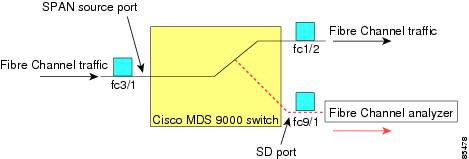
The SPAN feature is specific to switches in the Cisco MDS 9000 Family. It monitors network traffic through a Fibre Channel interface. Traffic through any Fibre Channel interface can be replicated to a special port called the SPAN destination port (SD port). Any Fibre Channel port in a switch can be configured as an SD port. Once an interface is in SD port mode, it cannot be used for normal data traffic. You can attach a Fibre Channel Analyzer to the SD port to monitor SPAN traffic.
SD ports do not receive frames, they only transmit a copy of the SPAN source traffic. The SPAN feature is nonintrusive and does not affect switching of network traffic for any SPAN source ports (see Figure 1).
SPAN Sources
SPAN sources refer to the interfaces from which traffic can be monitored. You can also specify VSAN as a SPAN source, in which case, all supported interfaces in the specified VSAN are included as SPAN sources. When a VSAN as a source is specified, then all physical ports and PortChannels in that VSAN are included as SPAN sources. You can choose the SPAN traffic in the ingress direction, the egress direction, or both directions for any source interface:
-
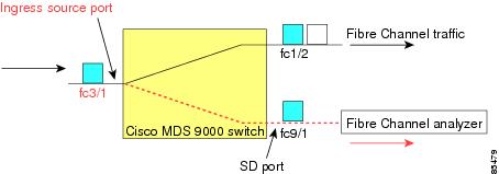
Ingress source (Rx)—Traffic entering the switch fabric through this source interface is spanned or copied to the SD port (see Figure 1).
-
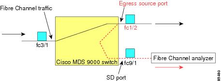
Egress source (Tx)—Traffic exiting the switch fabric through this source interface is spanned or copied to the SD port (see Figure 2).
IPS Source Ports
SPAN capabilities are available on the IP Storage Services (IPS) module. The SPAN feature is only implemented on the FCIP and iSCSI virtual Fibre Channel port interfaces, not the physical Gigabit Ethernet ports. You can configure SPAN for ingress traffic, egress traffic, or traffic in both directions for all eight iSCSI and 24 FCIP interfaces that are available in the IPS module.
 Note |
You can configure SPAN for Ethernet traffic using Cisco switches or routers connected to the Cisco MDS 9000 Family IPS modules. |
Allowed Source Interface Types
The SPAN feature is available for the following interface types:
- Physical ports such as F ports, FL ports, TE ports, E ports, and TL ports.
- Interface sup-fc0 (traffic
to and from the supervisor):
- The Fibre Channel traffic from the supervisor module to the switch fabric through the sup-fc0 interface is called ingress traffic. It is spanned when sup-fc0 is chosen as an ingress source port.
- The Fibre Channel traffic from the switch fabric to the supervisor module through the sup-fc0 interface is called egress traffic. It is spanned when sup-fc0 is chosen as an egress source port.
- PortChannels
- All ports in the PortChannel are included and spanned as sources.
- You cannot specify individual ports in a PortChannel as SPAN sources. Previously configured SPAN-specific interface information is discarded.
- IPS module specific Fibre Channel interfaces:
- iSCSI interfaces
- FCIP interfaces
Note |
In Cisco MDS 9700 Series Switches, iSCSI ports are not applicable for the Allowed Source Interface Types. |
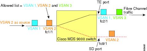
VSAN as a Source
SPAN sources refer to the interfaces from which traffic can be monitored. When a VSAN as a source is specified, then all physical ports and PortChannels in that VSAN are included as SPAN sources. A TE port is included only when the port VSAN of the TE port matches the source VSAN. A TE port is excluded even if the configured allowed VSAN list may have the source VSAN, but the port VSAN is different.
You cannot configure source interfaces (physical interfaces, PortChannels, or sup-fc interfaces) and source VSANs in the same SPAN session.
SPAN Sessions
Each SPAN session represents an association of one destination with a set of source(s) along with various other parameters that you specify to monitor the network traffic. One destination can be used by one or more SPAN sessions. You can configure up to 16 SPAN sessions in a switch. Each session can have several source ports and one destination port.
To activate any SPAN session, at least one source and the SD port must be up and functioning. Otherwise, traffic is not directed to the SD port.
 Tip |
A source can be shared by two sessions, however, each session must be in a different direction—one ingress and one egress. |
You can temporarily deactivate (suspend) any SPAN session. The traffic monitoring is stopped during this time.
Note |
On a Cisco MDS 9250i Multiservice Fabric switch, packet drops will occur if the SPAN port cannot keep up with incoming frame bursts. To avoid these packet drops, the speed of the SPAN destination port should be equal to the maximum speed of the source ports. However, when the source is an FCIP interface, the speed of the SPAN destination port should be more than 10G because the FCIP interface is running over a 10G Ethernet physical interface. |
Specifying Filters
You can perform VSAN-based filtering to selectively monitor network traffic on specified VSANs. You can apply this VSAN filter to all sources in a session (see ). Only VSANs present in the filter are spanned.
You can specify session VSAN filters that are applied to all sources in the specified session. These filters are bidirectional and apply to all sources configured in the session. Each SPAN session represents an association of one destination with a set of source(s) along with various other parameters that you specify to monitor the network traffic.
SD Port Characteristics
An SD port has the following characteristics:
- Ignores BB_credits.
- Allows data traffic only in the egress (Tx) direction.
- Does not require a device or an analyzer to be physically connected.
- Supports only 1 Gbps or 2 Gbps speeds. The auto speed option is not allowed.
- Multiple sessions can share the same destination ports.
- If the SD port is shut down, all shared sessions stop generating SPAN traffic.
- The outgoing frames can be encapsulated in Extended Inter-Switch Link (EISL) format.
- The SD port does not have a port VSAN.
- SD ports cannot be configured using Storage Services Modules (SSMs).
- The port mode cannot be changed if it is being used for a SPAN session.
Note |
|
SPAN Conversion Behavior
SPAN features (configured in any prior release) are converted as follows:
- If source interfaces and source VSANs are configured in a given session, then all the source VSANs are removed from that session.
For example, before Cisco MDS SAN-OS Release 1.0(4):
Session 1 (active)
   Destination is fc1/9
   No session filters configured
   Ingress (rx) sources are
      vsans 10-11
     fc1/3,
   Egress (tx) sources are
     fc1/3,
Once upgraded to Cisco MDS SAN-OS Release 1.1(1):
Session 1 (active)
   Destination is fc1/9
   No session filters configured
   Ingress (rx) sources are
     fc1/3,
   Egress (tx) sources are
     fc1/3,
For Cisco MDS 9700 Series Switches:
switch(config-if)# monitor session 1
switch(config-monitor)# source interface fc5/1
switch(config-monitor)# destination interface fc2/9
switch(config-monitor)# no shut
switch(config-monitor)# show monitor session all
session 1
---------------
ssn direction : both
state : up
source intf :
rx : fc5/1
tx : fc5/1
both : fc5/1
source VLANs :
rx :
tx :
both :
source exception :
rate-limit : Auto
filter VLANs : filter not specified
destination ports : fc2/9
Session 1 had both source interfaces and source VSANs before the upgrade. After the upgrade, the source VSANs were removed (rule 1).
- If interface level VSAN filters are configured in source interfaces, then the source interfaces are also removed from the session. If this interface is configured in both directions, it is removed from both directions.
For example, before Cisco MDS SAN-OS Release 1.0(4):
Session 2 (active)
   Destination is fc1/9
   No session filters configured
   Ingress (rx) sources are
      vsans 12
     fc1/6 (vsan 1-20),
   Egress (tx) sources are
     fc1/6 (vsan 1-20),
Once upgraded to Cisco MDS SAN-OS Release 1.1(1):
Session 2 (inactive as no active sources)
   Destination is fc1/9
   No session filters configured
   No ingress (rx) sources
   No egress (tx) sources
Note |
The deprecated configurations are removed from persistent memory once a switchover or a new startup configuration is implemented. |
Session 2 had a source VSAN 12 and a source interface fc1/6 with VSAN filters specified in Cisco MDS SAN-OS Release 1.0(4). When upgraded to Cisco MDS SAN-OS Release 1.1(1) the following changes are made:
-
- The source VSAN (VSAN 12) is removed (rule 1).
- The source interface fc1/6 had VSAN filters specified—it is also removed (rule 2).
Monitoring Traffic Using Fibre Channel Analyzers
You can use SPAN to monitor traffic on an interface without any traffic disruption. This feature is especially useful in troubleshooting scenarios in which traffic disruption changes the problem environment and makes it difficult to reproduce the problem. You can monitor traffic in either of the following two ways:
- Without SPAN
- With SPAN
Monitoring Without SPAN
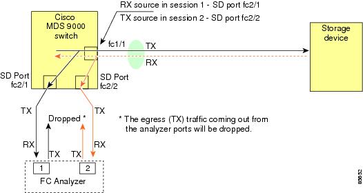
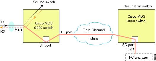
You can monitor traffic using interface fc1/1 in a Cisco MDS 9000 Family switch that is connected to another switch or host. You need to physically connect a Fibre Channel analyzer between the switch and the storage device to analyze the traffic through interface fc1/1 (see Figure 1).
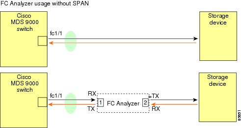
This type of connection has the following limitations:
-
It requires you to physically insert the FC analyzer between the two network devices.
-
It disrupts traffic when the Fibre Channel analyzer is physically connected.
-
The analyzer captures data only on the Rx links in both port 1 and port 2. Port 1 captures traffic exiting interface fc1/1 and port 2 captures ingress traffic into interface fc1/1.
Monitoring with SPAN
Using SPAN you can capture the same traffic scenario (see Figure 1) without any traffic disruption. The Fibre Channel analyzer uses the ingress (Rx) link at port 1 to capture all the frames going out of the interface fc1/1. It uses the ingress link at port 2 to capture all the ingress traffic on interface fc1/1.
Using SPAN you can monitor ingress traffic on fc1/1 at SD port fc2/2 and egress traffic on SD port fc2/1. This traffic is seamlessly captured by the FC analyzer (see Figure 1).
Single SD Port to Monitor Traffic
You do not need to use two SD ports to monitor bidirectional traffic on any interface (see Figure 1). You can use one SD port and one FC analyzer port by monitoring traffic on the interface at the same SD port fc2/1.
Figure 1 shows a SPAN setup where one session with destination port fc2/1 and source interface fc1/1 is used to capture traffic in both ingress and egress directions. This setup is more advantageous and cost effective than the setup shown in Figure 1. It uses one SD port and one port on the analyzer, instead of using a full, two-port analyzer.
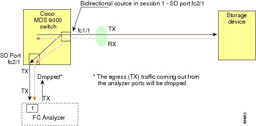
To use this setup, the analyzer should have the capability of distinguishing ingress and egress traffic for all captured frames.
SD Port Configuration
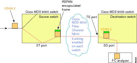
The SD port in the destination switch enables the FC analyzer to receive the RSPAN traffic from the Fibre Channel tunnel. Figure 1 depicts an RSPAN tunnel configuration, now that tunnel destination is also configured.

Note |
SD ports cannot be configured using Storage Services Modules (SSMs). |
Mapping the FC Tunnel
The tunnel-id-map option specifies the egress interface of the tunnel at the destination switch (see Figure 1).
Creating VSAN Interfaces
Figure 1 depicts a basic FC tunnel configuration.
Note |
This example assumes that VSAN 5 is already configured in the VSAN database. |
Remote SPAN
Note |
Remote SPAN is not supported on the Cisco Fabric Switch for HP c-Class BladeSystem, Cisco Fabric Switch for IBM BladeSystem, Cisco Fabric Switch 9250i, and Cisco Fabric Switch 9100S. |
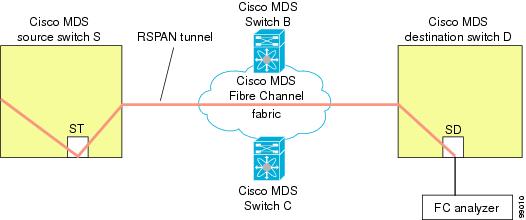
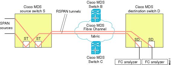
The Remote SPAN (RSPAN) feature enables you to remotely monitor traffic for one or more SPAN sources distributed in one or more source switches in a Fibre Channel fabric. The SPAN destination (SD) port is used for remote monitoring in a destination switch. A destination switch is usually different from the source switch(es) but is attached to the same Fibre Channel fabric. You can replicate and monitor traffic in any remote Cisco MDS 9000 Family switch or director, just as you would monitor traffic in a Cisco MDS source switch.
The RSPAN feature is nonintrusive and does not affect network traffic switching for those SPAN source ports. Traffic captured on the remote switch is tunneled across a Fibre Channel fabric which has trunking enabled on all switches in the path from the source switch to the destination switch. The Fibre Channel tunnel is structured using trunked ISL (TE) ports. In addition to TE ports, the RSPAN feature uses two other interface types (see Figure 1):
-
SD ports—A passive port from which remote SPAN traffic can be obtained by the FC analyzer.
-
ST ports—A SPAN tunnel (ST) port is an entry point port in the source switch for the RSPAN Fibre Channel tunnel. ST ports are special RSPAN ports and cannot be used for normal Fibre Channel traffic.
Advantages of Using RSPAN
The RSPAN features has the following advantages:
- Enables nondisruptive traffic monitoring at a remote location.
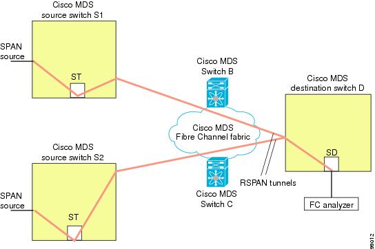
- Provides a cost effective solution by using one SD port to monitor remote traffic on multiple switches.
- Works with any Fibre Channel analyzer.
- Is compatible with the Cisco MDS 9000 Port Analyzer adapters.
- Does not affect traffic in the source switch, but shares the ISL bandwidth with other ports in the fabric.
FC and RSPAN Tunnels
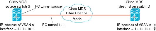
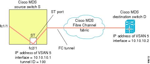
An FC tunnel is a logical data path between a source switch and a destination switch. The FC tunnel originates from the source switch and terminates at the remotely located destination switch.
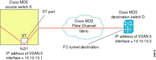
RSPAN uses a special Fibre Channel tunnel (FC tunnel) that originates at the ST port in the source switch and terminates at the SD port in the destination switch. You must bind the FC tunnel to an ST port in the source switch and map the same FC tunnel to an SD port in the destination switch. Once the mapping and binding is configured, the FC tunnel is referred to as an RSPAN tunnel (see Figure 1).

ST Port Configuration
Note |
In Cisco MDS 9700 Series Switches, SPAN tunnel port (ST port) is not supported. |
Once the FC tunnel is created, be sure to configure the ST port to bind it to the FC tunnel at the source switch. The FC tunnel becomes an RSPAN tunnel once the binding and mapping is complete.
Figure 1 depicts a basic FC tunnel configuration.
ST Port Characteristics
ST ports have the following characteristics:
- ST ports perform the RSPAN encapsulation of the FC frame.
- ST ports do not use BB_credits.
- One ST port can only be bound to one FC tunnel.
- ST ports cannot be used for any purpose other than to carry RSPAN traffic.
- ST ports cannot be configured using Storage Services Modules (SSMs).
Creating Explicit Paths
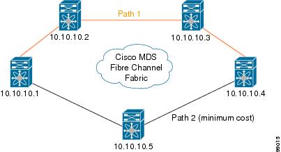
You can specify an explicit path through the Cisco MDS Fibre Channel fabric (source-based routing), using the explicit-path option. For example, if you have multiple paths to a tunnel destination, you can use this option to specify the FC tunnel to always take one path to the destination switch. The software then uses this specified path even if other paths are available.
This option is especially useful if you prefer to direct the traffic through a certain path although other paths are available. In an RSPAN situation, you can specify the explicit path so the RSPAN traffic does not interfere with the existing user traffic. You can create any number of explicit paths in a switch (see Figure 1).

 Feedback