- Index
- New and Changed Information
- Preface
- Interfaces Overview
- Configuring Interfaces
- Configuring Ethernet Interfaces
- Configuring Virtual Interfaces
- Configuring Fibre Channel Interfaces
- Configuring Interface Buffers
- Configuring Trunking
- Configuring Port Channels
- Configuring N Port Virtualizatio
- Configuring FlexAttach Virtual pWWN
Cisco Fabric Manager Interfaces Configuration Guide
Bias-Free Language
The documentation set for this product strives to use bias-free language. For the purposes of this documentation set, bias-free is defined as language that does not imply discrimination based on age, disability, gender, racial identity, ethnic identity, sexual orientation, socioeconomic status, and intersectionality. Exceptions may be present in the documentation due to language that is hardcoded in the user interfaces of the product software, language used based on RFP documentation, or language that is used by a referenced third-party product. Learn more about how Cisco is using Inclusive Language.
- Updated:
- December 21, 2009
Chapter: Configuring Virtual Interfaces
- About Virtual Fibre Channel Interfaces
- Guidelines and Limitations
- Configuring Virtual Fibre Channel Interfaces
- Default Settings
Configuring Virtual Fibre Channel Interfaces
This chapter describes how to configure virtual Fibre Channel (FC) interfaces on a Cisco Nexus 5000 Series switch.

Note ![]() Before you configure virtual FC interfaces on a Cisco Nexus 5000 Series switch, you must enable and configure FCoE on the switch. For information on enabling and configuring FCoE, refer to the Cisco Fabric Manager Fabric Configuration Guide.
Before you configure virtual FC interfaces on a Cisco Nexus 5000 Series switch, you must enable and configure FCoE on the switch. For information on enabling and configuring FCoE, refer to the Cisco Fabric Manager Fabric Configuration Guide.
This chapter includes the following sections:
•![]() About Virtual Fibre Channel Interfaces
About Virtual Fibre Channel Interfaces
•![]() Configuring Virtual Fibre Channel Interfaces
Configuring Virtual Fibre Channel Interfaces
About Virtual Fibre Channel Interfaces
Cisco Nexus 5000 Series switches support Fibre Channel over Ethernet (FCoE), which allows Fibre Channel and Ethernet traffic to be carried on the same physical Ethernet connection between the switch and the servers.
The Fibre Channel portion of FCoE is configured as a virtual Fibre Channel interface. Logical Fibre Channel features (such as interface mode) can be configured on virtual FC interfaces. A virtual FC interface must be bound to an interface before it can be used.
Note ![]() Virtual FC interfaces are created with the administrative state set to down. You need to explicitly configure the administrative state to bring the virtual FC interface into operation.
Virtual FC interfaces are created with the administrative state set to down. You need to explicitly configure the administrative state to bring the virtual FC interface into operation.
Guidelines and Limitations
When configuring virtual FC interfaces, note the following guidelines and limitations:
•![]() Each virtual FC interface can be bound to one of the following interfaces:
Each virtual FC interface can be bound to one of the following interfaces:
–![]() An Ethernet interface
An Ethernet interface
–![]() An Ethernet PortChannel
An Ethernet PortChannel
–![]() A media access control (MAC) address of an FCoE Node (ENode) or a remote Fibre Channel Forwarder (FCF) identified by the virtual FC interface
A media access control (MAC) address of an FCoE Node (ENode) or a remote Fibre Channel Forwarder (FCF) identified by the virtual FC interface
•![]() FCoE is supported only on 10-Gigabit Ethernet interfaces.
FCoE is supported only on 10-Gigabit Ethernet interfaces.
•![]() FCoE is not supported on private VLANs.
FCoE is not supported on private VLANs.
Configuring Virtual Fibre Channel Interfaces
This section describes how to configure virtual FC interfaces and includes the following topics:
•![]() Configuring a Virtual Fibre Channel Interface
Configuring a Virtual Fibre Channel Interface
•![]() Assigning Fibre Channel VSAN Membership
Assigning Fibre Channel VSAN Membership
•![]() Creating a Virtual Fibre Channel Interface
Creating a Virtual Fibre Channel Interface
•![]() Deleting a Virtual Fibre Channel Interface
Deleting a Virtual Fibre Channel Interface
Configuring a Virtual Fibre Channel Interface
You can configure a virtual FC interface on a Cisco Nexus 5000 Series switch that runs Cisco NX-OS Release 4.0(1a) or later releases. You can bind a virtual FC interface to a physical Ethernet interface, an Ethernet PortChannel, or a remote MAC address.
The Ethernet interface that you bind the virtual FC interface to must be configured as follows:
•![]() The Ethernet interface must be a trunk port (use the switchport mode trunk command).
The Ethernet interface must be a trunk port (use the switchport mode trunk command).
•![]() The FCoE VLAN that corresponds to the virtual Fibre Channel's VSAN must be in the allowed VLAN list.
The FCoE VLAN that corresponds to the virtual Fibre Channel's VSAN must be in the allowed VLAN list.
•![]() The FCoE VLAN must not be configured as the native VLAN of the trunk port.
The FCoE VLAN must not be configured as the native VLAN of the trunk port.
•![]() The Ethernet interface must be configured as PortFast (use the spanning-tree port type edge trunk command).
The Ethernet interface must be configured as PortFast (use the spanning-tree port type edge trunk command).
Following the above configuration guidelines will ensure a smooth upgrade to a T11 Fibre Channel Initialization Protocol (FIP)-based FCoE release in the future.
This section describes how to configure a virtual FC interface and includes the following topics:
•![]() Configuring a Virtual Fibre Channel Interface Using Fabric Manager
Configuring a Virtual Fibre Channel Interface Using Fabric Manager
•![]() Configuring a Virtual Fibre Channel Interface Using Device Manager
Configuring a Virtual Fibre Channel Interface Using Device Manager
•![]() Configuring a Virtual Fibre Channel Interface Using the Quick Configuration Tool
Configuring a Virtual Fibre Channel Interface Using the Quick Configuration Tool
Configuring a Virtual Fibre Channel Interface Using Fabric Manager
To configure virtual FC interfaces using Fabric Manager, follow these steps:
Step 1 ![]() In the Physical Attributes pane, expand Switches > Interfaces, and then choose VFC (FCoE).
In the Physical Attributes pane, expand Switches > Interfaces, and then choose VFC (FCoE).
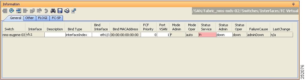
You see the FC Virtual information pane shown in Figure 4-1.
The General tab in the Information pane displays the description, bind type, bound interface, bound MAC address, FCF priority value, VSAN port, and status for each virtual FC interface.
Figure 4-1 FC Virtual Information Pane
Step 2 ![]() In the Information pane, in the FC Virtual table, click a virtual FC interface row to configure, and do the following:
In the Information pane, in the FC Virtual table, click a virtual FC interface row to configure, and do the following:
a. ![]() (Optional) You can modify the bind type for the selected virtual FC interface. To do so, click the Bind Type column. From the drop-down list, choose interfaceIndex or macAddress.
(Optional) You can modify the bind type for the selected virtual FC interface. To do so, click the Bind Type column. From the drop-down list, choose interfaceIndex or macAddress.
Note ![]() You cannot modify the bind type value of a virtual FC interface on a Cisco Nexus 5000 Series switch that runs a Cisco NX-OS release prior to Release 4.1(3). On such a switch, the Bind Type column will display interfaceIndex as the bind type.
You cannot modify the bind type value of a virtual FC interface on a Cisco Nexus 5000 Series switch that runs a Cisco NX-OS release prior to Release 4.1(3). On such a switch, the Bind Type column will display interfaceIndex as the bind type.
b. ![]() (Optional) Double-click the Bind Interface column to choose a physical Ethernet interface or Ethernet PortChannel that will be bound to the virtual FC interface. You can bind a virtual FC interface to an Ethernet PortChannel on a Cisco Nexus 5000 Series switch that runs Cisco NX-OS Release 4.1(3) or later releases.
(Optional) Double-click the Bind Interface column to choose a physical Ethernet interface or Ethernet PortChannel that will be bound to the virtual FC interface. You can bind a virtual FC interface to an Ethernet PortChannel on a Cisco Nexus 5000 Series switch that runs Cisco NX-OS Release 4.1(3) or later releases.
This column is dimmed if the Bind Type value is macAddress.
c. ![]() (Optional) Double-click the Bind MAC Address column to enter the MAC address of the ENode or the remote FCF.
(Optional) Double-click the Bind MAC Address column to enter the MAC address of the ENode or the remote FCF.
This column is dimmed if the Bind Type value is interfaceIndex.
d. ![]() (Optional) Double-click the FCF Priority column to enter a FCF priority value for the virtual FC interface. The value that you enter in this field will override the default FCF Priority value you configured in the FCoE Information pane. For more information on configuring FCoE, refer to the Cisco Fabric Manager Fabric Configuration Guide.
(Optional) Double-click the FCF Priority column to enter a FCF priority value for the virtual FC interface. The value that you enter in this field will override the default FCF Priority value you configured in the FCoE Information pane. For more information on configuring FCoE, refer to the Cisco Fabric Manager Fabric Configuration Guide.
Note ![]() You cannot modify the FCF Priority value on a Cisco Nexus 5000 Series switch that runs a Cisco NX-OS release prior to Release 4.1(3).
You cannot modify the FCF Priority value on a Cisco Nexus 5000 Series switch that runs a Cisco NX-OS release prior to Release 4.1(3).
e. ![]() In the Information pane toolbar, click the Apply Changes icon to save the configuration.
In the Information pane toolbar, click the Apply Changes icon to save the configuration.
Step 3 ![]() In the Information pane toolbar, click the Create Row icon to create a virtual FC interface. For more information, see the "Creating a Virtual Fibre Channel Interface Using Fabric Manager" section.
In the Information pane toolbar, click the Create Row icon to create a virtual FC interface. For more information, see the "Creating a Virtual Fibre Channel Interface Using Fabric Manager" section.
Step 4 ![]() In the Information pane toolbar, click the Delete Row icon to delete a virtual FC interface. For more information, see the "Deleting a Virtual Fibre Channel Interface" section.
In the Information pane toolbar, click the Delete Row icon to delete a virtual FC interface. For more information, see the "Deleting a Virtual Fibre Channel Interface" section.
Configuring a Virtual Fibre Channel Interface Using Device Manager
To configure virtual FC interfaces using Device Manager, follow these steps:
Step 1 ![]() Launch Device Manager from the Cisco Nexus 5000 Series switch.
Launch Device Manager from the Cisco Nexus 5000 Series switch.
Step 2 ![]() Choose Interface > Virtual Interfaces > Fibre Channel.
Choose Interface > Virtual Interfaces > Fibre Channel.
You see the Virtual FC Interfaces dialog box shown in Figure 4-2.
The General tab displays the description, bind type, bound interface, bound MAC address, FCF priority value, VSAN port, and status for each virtual FC interface.
Figure 4-2 Virtual FC Interfaces Dialog Box

Step 3 ![]() Click a virtual FC interface row to configure. Modify the values for the virtual FC interface.
Click a virtual FC interface row to configure. Modify the values for the virtual FC interface.
For more information, see the "Configuring a Virtual Fibre Channel Interface Using Fabric Manager" section.
Step 4 ![]() Click Apply to save the configuration.
Click Apply to save the configuration.
Step 5 ![]() Click Create to create a virtual FC interface. For more information, see the "Creating a Virtual Fibre Channel Interface Using Device Manager" section.
Click Create to create a virtual FC interface. For more information, see the "Creating a Virtual Fibre Channel Interface Using Device Manager" section.
Step 6 ![]() Click Delete to delete a virtual FC interface. For more information, see the "Deleting a Virtual Fibre Channel Interface" section.
Click Delete to delete a virtual FC interface. For more information, see the "Deleting a Virtual Fibre Channel Interface" section.
Configuring a Virtual Fibre Channel Interface Using the Quick Configuration Tool
The Quick Configuration Tool allows you to bind virtual FC interfaces to Ethernet interfaces or Ethernet PortChannels and enable or disable the FCoE feature on the Cisco Nexus 5000 Series switch. The tool allows you to select one of the following configurations for each Ethernet interface:
•![]() Eth Only—Configures the physical Ethernet without any virtual FC interfaces.
Eth Only—Configures the physical Ethernet without any virtual FC interfaces.
•![]() vFC Only—Configures the physical Ethernet or Ethernet PortChannel to have an associated virtual FC interface.
vFC Only—Configures the physical Ethernet or Ethernet PortChannel to have an associated virtual FC interface.
To bind virtual FC interfaces or enable FCoE features on the Ethernet interfaces using the Quick Configuration Tool, follow these steps:
Step 1 ![]() Launch Device Manager from the Cisco Nexus 5000 Series switch.
Launch Device Manager from the Cisco Nexus 5000 Series switch.
Step 2 ![]() Choose Interface > Quick Configuration Tool.
Choose Interface > Quick Configuration Tool.
You see the Quick Configuration Tool dialog box shown in Figure 4-3.
The Interface column displays the physical Ethernet interfaces, followed by the Ethernet PortChannels.
Figure 4-3 Quick Configuration Tool

Step 3 ![]() In the Switch Operational Type area, click Ethernet Switch if you are configuring the switch as a pure Ethernet switch. Click FCoE Switch if you are configuring the switch with Fibre Channel and FCoE interfaces.
In the Switch Operational Type area, click Ethernet Switch if you are configuring the switch as a pure Ethernet switch. Click FCoE Switch if you are configuring the switch with Fibre Channel and FCoE interfaces.
Step 4 ![]() Do one of the following:
Do one of the following:
a. ![]() (Optional) In the column header, click the radio button to set all of the interfaces to the value in the selected column.
(Optional) In the column header, click the radio button to set all of the interfaces to the value in the selected column.
b. ![]() For each row, click the radio button for the configuration that you want to apply to this interface.
For each row, click the radio button for the configuration that you want to apply to this interface.
Step 5 ![]() Click Apply.
Click Apply.
Device Manager enables or disables the FCoE feature on the interfaces, depending on whether you clicked the virtual Fibre Channel (vFC Only) or Ethernet (Eth only) radio button.
Depending on the type of switch that you chose in the Switch Operational Type area, Device Manager does one of the following:
•![]() If the FCoE feature was enabled on the switch, and you chose the Ethernet Switch radio button, a confirmation message appears asking if you would like to disable the FCoE feature. Click Yes if you want Device Manager to disable the FCoE feature and save the configuration.
If the FCoE feature was enabled on the switch, and you chose the Ethernet Switch radio button, a confirmation message appears asking if you would like to disable the FCoE feature. Click Yes if you want Device Manager to disable the FCoE feature and save the configuration.
•![]() If the FCoE feature was disabled on the switch, and you chose the FCoE Switch radio button, and then chose the virtual Fibre Channel (vFC Only) radio button, a confirmation message appears asking if you would like to enable the FCoE feature. Click Yes if you want Device Manager to enable the FCoE feature and save the configuration.
If the FCoE feature was disabled on the switch, and you chose the FCoE Switch radio button, and then chose the virtual Fibre Channel (vFC Only) radio button, a confirmation message appears asking if you would like to enable the FCoE feature. Click Yes if you want Device Manager to enable the FCoE feature and save the configuration.
Note ![]() If you enable or disable the FCoE feature on a Cisco Nexus 5000 Series switch that runs a Cisco NX-OS release prior to Release 4.2(1), Device Manager will automatically reboot the switch after enabling or disabling the FCoE feature.
If you enable or disable the FCoE feature on a Cisco Nexus 5000 Series switch that runs a Cisco NX-OS release prior to Release 4.2(1), Device Manager will automatically reboot the switch after enabling or disabling the FCoE feature.
Mapping VSANs to VLANs
A VSAN-VLAN mapping indicates the VLAN that is used to transport Fibre Channel traffic for a specific VSAN. Each virtual FC interface is associated with only one VSAN. Any VSAN with associated virtual FC interfaces must be mapped to a dedicated FCoE-enabled VLAN. FCoE is not supported on private VLANs.
This section provides information about how to map a VSAN to a VLAN and includes the following topics:
•![]() Mapping VSANs to VLANs Using Fabric Manager
Mapping VSANs to VLANs Using Fabric Manager
•![]() Mapping VSANs to VLANs Using Device Manager
Mapping VSANs to VLANs Using Device Manager
Mapping VSANs to VLANs Using Fabric Manager
To create a mapping between a VSAN and its associated VLAN using Fabric Manager, follow these steps:
Step 1 ![]() In the Physical Attributes pane, choose Switches > FCoE.
In the Physical Attributes pane, choose Switches > FCoE.
Step 2 ![]() In the Information pane, click the VSAN-VLAN Mapping tab.
In the Information pane, click the VSAN-VLAN Mapping tab.
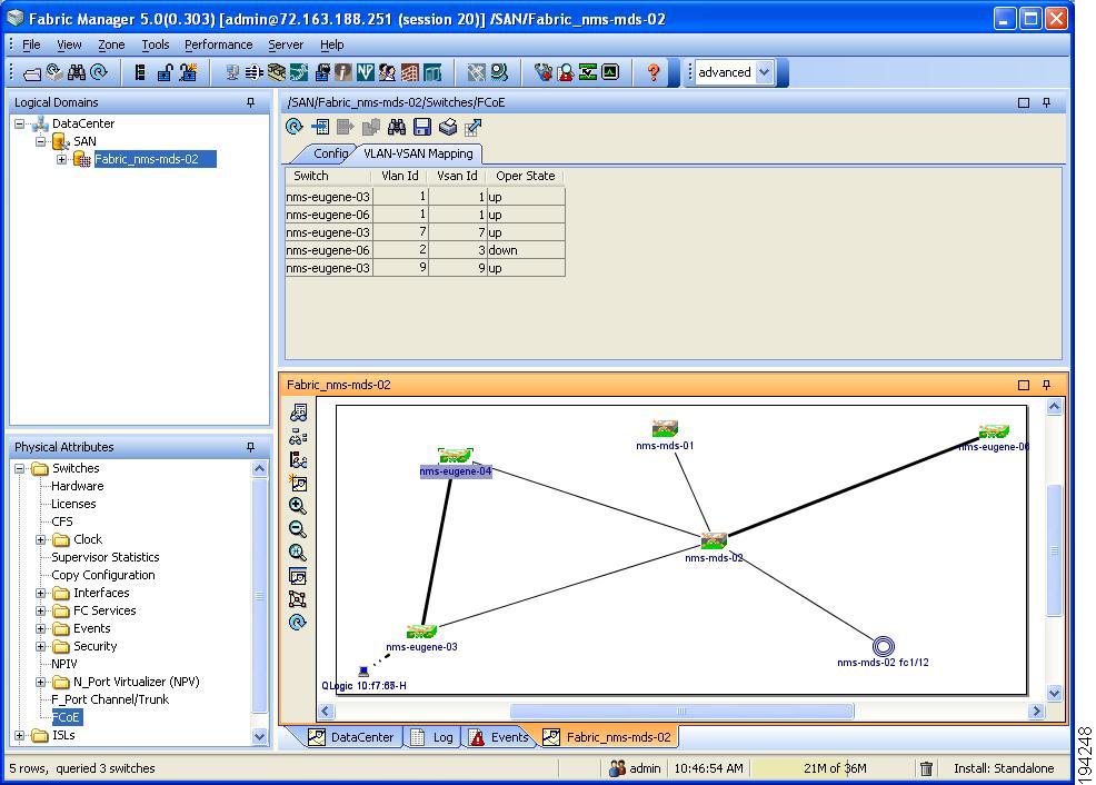
You see the VSAN-VLAN Mapping information pane shown in Figure 4-4.
The VSAN-VLAN Mapping tab displays the existing VSAN-VLAN mappings and the operational state of the VSAN-VLAN associations. You cannot modify an existing VSAN-VLAN mapping.
Figure 4-4 VSAN-VLAN Mapping Information Pane
Step 3 ![]() In the Information pane toolbar, click the Create Row icon to create a new mapping.
In the Information pane toolbar, click the Create Row icon to create a new mapping.
Note ![]() You must have a Cisco Nexus 5000 Series switch in the fabric to map a VSAN to a VLAN.
You must have a Cisco Nexus 5000 Series switch in the fabric to map a VSAN to a VLAN.
You see the Create dialog box shown in Figure 4-5.
Figure 4-5 Create VSAN-VLAN Mapping
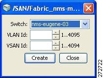
Step 4 ![]() From the Switch drop-down list, choose a Cisco Nexus 5000 Series switch.
From the Switch drop-down list, choose a Cisco Nexus 5000 Series switch.
Step 5 ![]() In the VSAN Id and VLAN Id fields, enter the VSAN ID and the VLAN ID that will be mapped together.
In the VSAN Id and VLAN Id fields, enter the VSAN ID and the VLAN ID that will be mapped together.
Step 6 ![]() Click Create to create the mapping.
Click Create to create the mapping.
Mapping VSANs to VLANs Using Device Manager
To create a mapping between a VSAN and its associated VLAN using Device Manager, follow these steps:
Step 1 ![]() Launch Device Manager from the Cisco Nexus 5000 Series switch.
Launch Device Manager from the Cisco Nexus 5000 Series switch.
Step 2 ![]() Choose FCoE > Config.
Choose FCoE > Config.
You see the FCoE Config dialog box shown in Figure 4-6.
Figure 4-6 FCoE Config Dialog Box

Step 3 ![]() Click the VSAN-VLAN Mapping tab.
Click the VSAN-VLAN Mapping tab.
The VSAN-VLAN Mapping tab lists the existing VSAN-VLAN mappings and the operational state of the VSAN-VLAN associations. You cannot modify an existing VSAN-VLAN mapping.
Step 4 ![]() Click Create to create a new mapping.
Click Create to create a new mapping.
You see the Create VSAN-VLAN Mapping dialog box shown in Figure 4-7.
Figure 4-7 Create VSAN-VLAN Mapping

Step 5 ![]() In the VSAN Id and VLAN Id fields, enter the VSAN ID and the VLAN ID that will be mapped together.
In the VSAN Id and VLAN Id fields, enter the VSAN ID and the VLAN ID that will be mapped together.
Step 6 ![]() Click Create to create the mapping.
Click Create to create the mapping.
Assigning Fibre Channel VSAN Membership
To associate a virtual FC interface with a VSAN port using Device Manager, follow these steps:
Step 1 ![]() Launch Device Manager from the Cisco Nexus 5000 Series switch.
Launch Device Manager from the Cisco Nexus 5000 Series switch.
Step 2 ![]() Choose FC > VSANs.
Choose FC > VSANs.
You see the VSAN dialog box shown in Figure 4-8.
Figure 4-8 VSAN Dialog Box
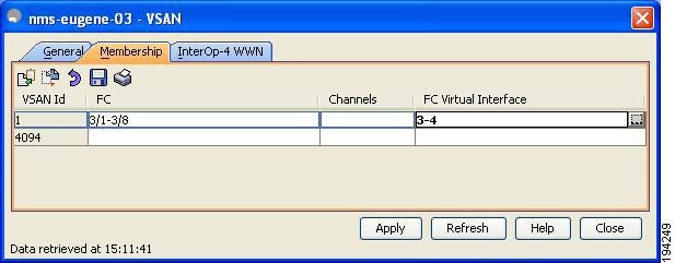
Step 3 ![]() Click the Membership tab. This tab displays the virtual FC interfaces associated with VSAN ports.
Click the Membership tab. This tab displays the virtual FC interfaces associated with VSAN ports.
Step 4 ![]() For each VSAN port in the table, double-click the following VSAN parameters and choose a value to associate the virtual FC interface with the VSAN:
For each VSAN port in the table, double-click the following VSAN parameters and choose a value to associate the virtual FC interface with the VSAN:
•![]() FC—Fibre Channel ports in VSAN
FC—Fibre Channel ports in VSAN
•![]() Channels—Ethernet PortChannels in VSAN
Channels—Ethernet PortChannels in VSAN
•![]() FC Virtual Interface—Fibre Channel virtual interface to associate with the VSAN port
FC Virtual Interface—Fibre Channel virtual interface to associate with the VSAN port
Step 5 ![]() Click Apply to save the changes.
Click Apply to save the changes.
Creating a Virtual Fibre Channel Interface
This section describes how to create a virtual FC interface and includes the following topics:
•![]() Creating a Virtual Fibre Channel Interface Using Fabric Manager
Creating a Virtual Fibre Channel Interface Using Fabric Manager
•![]() Creating a Virtual Fibre Channel Interface Using Device Manager
Creating a Virtual Fibre Channel Interface Using Device Manager
Creating a Virtual Fibre Channel Interface Using Fabric Manager
To create a virtual FC interface using Fabric Manager, follow these steps:
Step 1 ![]() In the Physical Attributes pane, expand Switches > Interfaces, and then choose VFC (FCoE).
In the Physical Attributes pane, expand Switches > Interfaces, and then choose VFC (FCoE).
Note ![]() Cisco Fabric Manager 4.1(2) and later releases do not support the configuration of a virtual FC interface on a Cisco Nexus 5000 Series switch that runs a Cisco NX-OS release prior to Release 4.0(1a). Fabric Manager issues an error message if you try to configure a virtual FC interface on a Cisco Nexus 5000 Series switch that runs a Cisco NX-OS release prior to Release 4.0(1a).
Cisco Fabric Manager 4.1(2) and later releases do not support the configuration of a virtual FC interface on a Cisco Nexus 5000 Series switch that runs a Cisco NX-OS release prior to Release 4.0(1a). Fabric Manager issues an error message if you try to configure a virtual FC interface on a Cisco Nexus 5000 Series switch that runs a Cisco NX-OS release prior to Release 4.0(1a).
Step 2 ![]() In the Information pane toolbar, click the Create Row icon.
In the Information pane toolbar, click the Create Row icon.
You see the Create Virtual Interface dialog box shown in Figure 4-9.
Figure 4-9 Create Virtual Interface Dialog Box
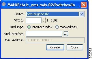
Step 3 ![]() From the Switch drop-down list, choose the switch where the virtual FC interface will be created.
From the Switch drop-down list, choose the switch where the virtual FC interface will be created.
Fabric Manager preselects the next available virtual FC interface ID. Optionally, in the VFC ID field, enter a value for this ID as an integer from 1 to 8192.
Step 4 ![]() (Optional) To bind the virtual FC interface to an Ethernet interface or an Ethernet PortChannel, do the following:
(Optional) To bind the virtual FC interface to an Ethernet interface or an Ethernet PortChannel, do the following:
a. ![]() Ensure that the interfaceIndex radio button is selected. The interfaceIndex radio button is selected by default.
Ensure that the interfaceIndex radio button is selected. The interfaceIndex radio button is selected by default.
b. ![]() Click the button located next to the Bind Interface field, and choose the physical Ethernet interface or Ethernet PortChannel number that will be bound to this virtual FC interface. Optionally, you can enter a value for the Ethernet interface or Ethernet PortChannel in the Bind Interface field.
Click the button located next to the Bind Interface field, and choose the physical Ethernet interface or Ethernet PortChannel number that will be bound to this virtual FC interface. Optionally, you can enter a value for the Ethernet interface or Ethernet PortChannel in the Bind Interface field.
Step 5 ![]() (Optional) To bind the virtual FC interface to the MAC address of the ENode or the remote FCF, do the following:
(Optional) To bind the virtual FC interface to the MAC address of the ENode or the remote FCF, do the following:
a. ![]() Click the macAddress radio button.
Click the macAddress radio button.
b. ![]() In the MAC Address field, enter the MAC address of the ENode or the remote FCF identified by the virtual FC interface. For example, 00:15:60:0F:C1:D0.
In the MAC Address field, enter the MAC address of the ENode or the remote FCF identified by the virtual FC interface. For example, 00:15:60:0F:C1:D0.
Step 6 ![]() Click Create.
Click Create.
Step 7 ![]() (Optional) Repeat Step 3 through Step 6 to create additional virtual FC interfaces for the same switch or a different switch.
(Optional) Repeat Step 3 through Step 6 to create additional virtual FC interfaces for the same switch or a different switch.
Step 8 ![]() In the Create Virtual Interface dialog box, click Close when done.
In the Create Virtual Interface dialog box, click Close when done.
The FC Virtual information pane lists the new and existing virtual FC interfaces for the switch.
Creating a Virtual Fibre Channel Interface Using Device Manager
To create a virtual FC interface using Device Manager, follow these steps:
Step 1 ![]() Launch Device Manager from the Cisco Nexus 5000 Series switch.
Launch Device Manager from the Cisco Nexus 5000 Series switch.
Step 2 ![]() Choose Interface > Virtual Interfaces > Fibre Channel.
Choose Interface > Virtual Interfaces > Fibre Channel.
You see the Virtual FC Interfaces dialog box (see Figure 4-2).
The General tab displays the description, bind type, bound Ethernet interface or PortChannel, bound MAC address, FCF priority value, VSAN port, and status for each virtual FC interface.
Step 3 ![]() Click Create.
Click Create.
You see the Create Virtual FC Interfaces General dialog box shown in Figure 4-10.
Figure 4-10 Create Virtual FC Interfaces Dialog Box
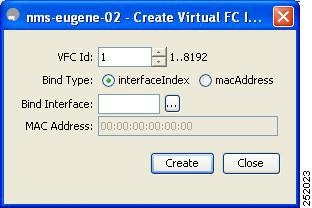
Step 4 ![]() In the VFC Id field, enter the virtual FC interface ID as an integer from 1 to 8192. The VFC Id field increments by 1.
In the VFC Id field, enter the virtual FC interface ID as an integer from 1 to 8192. The VFC Id field increments by 1.
Step 5 ![]() (Optional) To bind the virtual FC interface to an Ethernet interface or an Ethernet PortChannel, do the following:
(Optional) To bind the virtual FC interface to an Ethernet interface or an Ethernet PortChannel, do the following:
a. ![]() Ensure that the interfaceIndex radio button is selected. The interfaceIndex radio button is selected by default.
Ensure that the interfaceIndex radio button is selected. The interfaceIndex radio button is selected by default.
b. ![]() Click the button located next to the Bind Interface field, and choose the physical Ethernet interface or Ethernet PortChannel to bind to the virtual FC interface. Optionally, you can enter a value for the Ethernet interface or Ethernet PortChannel in the Bind Interface field.
Click the button located next to the Bind Interface field, and choose the physical Ethernet interface or Ethernet PortChannel to bind to the virtual FC interface. Optionally, you can enter a value for the Ethernet interface or Ethernet PortChannel in the Bind Interface field.
Note ![]() You cannot bind a virtual FC interface to an Ethernet interface that runs at 1-Gigabit Ethernet.
You cannot bind a virtual FC interface to an Ethernet interface that runs at 1-Gigabit Ethernet.
Step 6 ![]() (Optional) To bind the virtual FC interface to the MAC address of the ENode or the remote FCF, do the following:
(Optional) To bind the virtual FC interface to the MAC address of the ENode or the remote FCF, do the following:
a. ![]() Click the macAddress radio button.
Click the macAddress radio button.
b. ![]() In the MAC Address field, enter the MAC address of the ENode or the remote FCF identified by the virtual FC interface. For example, 00:15:60:0F:C1:D0.
In the MAC Address field, enter the MAC address of the ENode or the remote FCF identified by the virtual FC interface. For example, 00:15:60:0F:C1:D0.
Step 7 ![]() Click Create.
Click Create.
You see the virtual FC interface in the Virtual FC Interfaces dialog box.
Step 8 ![]() (Optional) Repeat Step 4 through Step 7 to create additional virtual FC interfaces.
(Optional) Repeat Step 4 through Step 7 to create additional virtual FC interfaces.
Step 9 ![]() In the Create Virtual FC Interfaces General dialog box, click Close when done.
In the Create Virtual FC Interfaces General dialog box, click Close when done.
The Virtual FC Interfaces dialog box lists the new and existing virtual FC interfaces for the switch.
Deleting a Virtual Fibre Channel Interface
You can delete a virtual FC interface using Fabric Manager or Device Manager.
To delete a virtual FC interface, follow these steps:
Step 1 ![]() Do one of the following:
Do one of the following:
•![]() In Fabric Manager, in the Physical Attributes pane, expand Switches > Interfaces, and then choose VFC (FCoE).
In Fabric Manager, in the Physical Attributes pane, expand Switches > Interfaces, and then choose VFC (FCoE).
You see the Virtual Fibre Channel table in the Information pane.
•![]() Launch Device Manager from the Cisco Nexus 5000 Series switch, and then choose Interface > Virtual Interfaces > Fibre Channel.
Launch Device Manager from the Cisco Nexus 5000 Series switch, and then choose Interface > Virtual Interfaces > Fibre Channel.
You see the Virtual FC Interfaces dialog box.
Step 2 ![]() Choose a virtual FC interface that you want to delete.
Choose a virtual FC interface that you want to delete.
Step 3 ![]() Do one of the following:
Do one of the following:
•![]() In Fabric Manager, in the Information pane toolbar, click the Delete Row icon.
In Fabric Manager, in the Information pane toolbar, click the Delete Row icon.
•![]() In Device Manager, in the Virtual FC Interfaces dialog box, click Delete.
In Device Manager, in the Virtual FC Interfaces dialog box, click Delete.
In the confirmation dialog box that appears, confirm the deletion of the virtual FC interface.
Default Settings
Table 4-1 lists the default settings for all virtual FC interfaces.
|
|
|
|---|---|
VSAN ID Port |
1 |
Mode Admin |
False |
Mode Oper |
Auto |
Status Service |
In |
Status Admin |
Down |
 Feedback