Cisco Nexus 1000V Installation and Upgrade Guide, Release 4.2(1)SV1(5.1)
Bias-Free Language
The documentation set for this product strives to use bias-free language. For the purposes of this documentation set, bias-free is defined as language that does not imply discrimination based on age, disability, gender, racial identity, ethnic identity, sexual orientation, socioeconomic status, and intersectionality. Exceptions may be present in the documentation due to language that is hardcoded in the user interfaces of the product software, language used based on RFP documentation, or language that is used by a referenced third-party product. Learn more about how Cisco is using Inclusive Language.
- Updated:
- January 31, 2012
Chapter: ISO and OVA Installation
Installing the Cisco Nexus 1000V Software Using ISO or OVA Files
The following chapter describes how to install the Cisco Nexus 1000V using an ISO or OVA file.
This chapter contains the following sections:
•![]() Installing the Software from the ISO Image
Installing the Software from the ISO Image
•![]() Installing the Software from an OVA Image
Installing the Software from an OVA Image
•![]() Establishing the SVS Connection
Establishing the SVS Connection
Installing the VSM Software
You can install the VSM software by using either the ISO file or the OVA file.
The workflow for installing the VSM software from an ISO file is as follows:
1. ![]() Installing the Software from the ISO Image
Installing the Software from the ISO Image
2. ![]() Establishing the SVS Connection
Establishing the SVS Connection
The workflow for installing the VSM software from an OVA file is as follows:
1. ![]() Installing the Software from an OVA Image
Installing the Software from an OVA Image
2. ![]() Establishing the SVS Connection
Establishing the SVS Connection
Installing the Software from the ISO Image
You can install the VSM software using the ISO image file from the CD.
BEFORE YOU BEGIN
Before beginning this procedure you must know or do the following:
•![]() The ISO image is located at zip_file_location/Nexus1000v.4.2.1.SV1.5.1/VSM/Install/ nexus-1000v.4.2.1.SV1.5.1.iso
The ISO image is located at zip_file_location/Nexus1000v.4.2.1.SV1.5.1/VSM/Install/ nexus-1000v.4.2.1.SV1.5.1.iso
•![]() You have already read the "Prerequisites for Installing the Cisco Nexus 1000V" section.
You have already read the "Prerequisites for Installing the Cisco Nexus 1000V" section.
•![]() You have already manually provisioned the VM to be used for the VSM. For more information, see the vSphere Virtual Machine Administration Guide.
You have already manually provisioned the VM to be used for the VSM. For more information, see the vSphere Virtual Machine Administration Guide.
•![]() The VSM VM requires the following and this procedure includes steps for updating these properties:
The VSM VM requires the following and this procedure includes steps for updating these properties:
–![]() Minimum of 2 GB of RAM reserved and allocated.
Minimum of 2 GB of RAM reserved and allocated.
–![]() Minimum CPU speed of 1500 MHz.
Minimum CPU speed of 1500 MHz.
•![]() Do not create more than one virtual CPU. The Cisco Nexus 1000V supports only one virtual CPU.
Do not create more than one virtual CPU. The Cisco Nexus 1000V supports only one virtual CPU.
PROCEDURE
Step 1 ![]() Using your VMware documentation, attach the VSM ISO image to the virtual CD-ROM and copy the software to a virtual machine (VM).
Using your VMware documentation, attach the VSM ISO image to the virtual CD-ROM and copy the software to a virtual machine (VM).
Step 2 ![]() Make sure that the VSM VM is powered off.
Make sure that the VSM VM is powered off.
Step 3 ![]() In the vSphere client Virtual Machine Properties window Hardware tab, choose Memory.
In the vSphere client Virtual Machine Properties window Hardware tab, choose Memory.
The Memory Configuration settings display in the right-hand pane.
Step 4 ![]() In the Memory Size field, choose 2 GB.
In the Memory Size field, choose 2 GB.
Step 5 ![]() In the Resources tab, choose Memory.
In the Resources tab, choose Memory.
The Resource Allocation settings display in the right-hand pane.
Step 6 ![]() In the Reservation field, choose 2048 MB.
In the Reservation field, choose 2048 MB.
Step 7 ![]() In the Resources tab, choose CPU.
In the Resources tab, choose CPU.
The Resource Allocation settings display in the right-hand pane.
Step 8 ![]() In the Reservation field, choose 1500 MHz.
In the Reservation field, choose 1500 MHz.
Step 9 ![]() Click OK.
Click OK.
The VSM VM memory and CPU speed settings are saved in VMware vSphere Client.
Step 10 ![]() Right-click the VSM and choose Open Console.
Right-click the VSM and choose Open Console.
The Install Nexus1000V and Bring Up the New Image window opens. See Figure B-1.
Figure B-1 Install Nexus1000V and Bring Up the New Image Window

Step 11 ![]() Choose the Install Nexus1000V and bring up the new image entry and press Enter.
Choose the Install Nexus1000V and bring up the new image entry and press Enter.
The System Admin Account Setup window opens. See Figure B-2.
Figure B-2 System Admin Account Setup Window

Step 12 ![]() Enter and confirm the Administrator password.
Enter and confirm the Administrator password.

Note ![]() All alphanumeric characters and symbols on a standard US keyboard are allowed except for these three: $ \ ?
All alphanumeric characters and symbols on a standard US keyboard are allowed except for these three: $ \ ?
---- System Admin Account Setup ----Confirm the password for
Enter the password for "admin": "admin":
Step 13 ![]() Enter the domain ID.
Enter the domain ID.
Enter the domain id<1-4095>: 152
Step 14 ![]() Enter the HA role.
Enter the HA role.
If you do not specify a role, standalone is assigned by default.
This example shows the HA role as primary.
Enter HA role[standalone/primary/secondary]: primary
[#########################################] 100%
---- Basic System Configuration Dialog ----
This setup utility will guide you through the basic configuration of
the system. Setup configures only enough connectivity for management
of the system.
*Note: setup is mainly used for configuring the system initially,
when no configuration is present. So setup always assumes system
defaults and not the current system configuration values.
Press Enter at anytime to skip a dialog. Use ctrl-c at anytime
to skip the remaining dialogs.
Would you like to enter the basic configuration dialog (yes/no):
This example shows the HA role as secondary.
Enter HA role[standalone/primary/secondary]: secondary
Setting HA role to secondary will cause a system reboot. Are you sure (yes/no) ? :
Step 15 ![]() Do one of the following:
Do one of the following:
•![]() If you are setting up the primary/active VSM, go to Step 18.
If you are setting up the primary/active VSM, go to Step 18.
•![]() If you are setting up the secondary/standby VSM, then continue with the next step.
If you are setting up the secondary/standby VSM, then continue with the next step.
Step 16 ![]() If you have set up the VSM virtual machine (VM) to boot from the CD-ROM, and are installing the secondary VSM from the ISO image attached to your CD-ROM, remove the virtual CD-ROM now so that the VSM does not boot from the CD.
If you have set up the VSM virtual machine (VM) to boot from the CD-ROM, and are installing the secondary VSM from the ISO image attached to your CD-ROM, remove the virtual CD-ROM now so that the VSM does not boot from the CD.
This step is necessary if you have set up the VSM VM to boot from the CD-ROM before the hard drive.
Step 17 ![]() If you are setting up the secondary/standby VSM, when prompted to reboot the VSM, answer yes.
If you are setting up the secondary/standby VSM, when prompted to reboot the VSM, answer yes.
The secondary VSM VM is rebooted and brought up in standby mode.
The password on the secondary VSM is synchronized with the password on the active/primary VSM.
Any configuration made on the active/primary VSM is now automatically synchronized with the standby.
This example show the system rebooting when the HA role is set to secondary.
Setting HA role to secondary will cause a system reboot. Are you sure (yes/no) ? :y
[########################################] 100%
HA mode set to secondary. Rebooting now...
You have completed this procedure for the secondary VSM.
Step 18 ![]() Enter yes to enter the basic configuration dialog.
Enter yes to enter the basic configuration dialog.
Would you like to enter the basic configuration dialog (yes/no): yes
Step 19 ![]() Enter no to create another Login account.
Enter no to create another Login account.
Create another login account (yes/no) [n]: no
Step 20 ![]() Enter no to configure a read-only SNMP community string.
Enter no to configure a read-only SNMP community string.
Configure read-only SNMP community string (yes/no) [n]: no
Step 21 ![]() Enter no to configure a read-write SNMP community string.
Enter no to configure a read-write SNMP community string.
Configure read-write SNMP community string (yes/no) [n]: no
Step 22 ![]() Enter a name for the switch.
Enter a name for the switch.
Enter the switch name: n1000v
Step 23 ![]() Enter yes to configure out-of-band management and then enter the mgmt0 IPv4 address and subnet mask.
Enter yes to configure out-of-band management and then enter the mgmt0 IPv4 address and subnet mask.
Continue with Out-of-band (mgmt0) management configuration? [yes/no] [y]: yes
Mgmt0 IPv4 address: 172.28.15.152
Mgmt0 IPv4 netmask: 255.255.255.0
Step 24 ![]() Enter yes to configure the default gateway.
Enter yes to configure the default gateway.
Configure the default-gateway: (yes/no) [y]: yes
IPv4 address of the default gateway : 172.23.233.1
Step 25 ![]() Enter no to configure advanced IP options.
Enter no to configure advanced IP options.
Configure Advanced IP options (yes/no)? [n]: no
Step 26 ![]() Enter yes to enable the Telnet service.
Enter yes to enable the Telnet service.
Enable the telnet service? (yes/no) [y]: yes
Step 27 ![]() Enter yes to enable the SSH service and then enter the key type and number of key bits.
Enter yes to enable the SSH service and then enter the key type and number of key bits.
For more information, see the document,Cisco Nexus 1000V Security Configuration Guide, Release 4.2(1)SV1(5.1).
Enable the ssh service? (yes/no) [y]: yes
Type of ssh key you would like to generate (dsa/rsa) : rsa
Number of  key bits <768-2048> : 1024
Step 28 ![]() Enter yes to enable the HTTP server.
Enter yes to enable the HTTP server.
Enable the http-server? (yes/no) [y]: yes
Step 29 ![]() Enter no to configure the NTP server.
Enter no to configure the NTP server.
Configure NTP server? (yes/no) [n]: no
Step 30 ![]() Enter yes to configure the SVS domain parameters and then enter the mode (L2 or L3), and the control and packet VLAN IDs.
Enter yes to configure the SVS domain parameters and then enter the mode (L2 or L3), and the control and packet VLAN IDs.
Configure svs domain parameters? (yes/no) [y]: yes
Enter SVS Control mode (L2 / L3) : L2
Enter control vlan <1-3967, 4048-4093> : 100
Enter packet vlan <1-3967, 4048-4093> : 101
Step 31 ![]() Enter yes to configure the VEM feature level and then enter 0 or 1.
Enter yes to configure the VEM feature level and then enter 0 or 1.
Vem feature level will be set to 4.2(1)SV1(5.1),
Do you want to reconfigure? (yes/no) [n] yes
Current vem feature level is set to 4.2(1)SV1(5.1)
You can change the feature level to:
vem feature level is set to the highest value possible
Note ![]() The feature level is the least VEM version that the VSM can support. For example, if the feature level is set to 4.2(1)SV1(5.1) release, any VEMs with an earlier version will not be attached to the VSM.
The feature level is the least VEM version that the VSM can support. For example, if the feature level is set to 4.2(1)SV1(5.1) release, any VEMs with an earlier version will not be attached to the VSM.
The system now summarizes the complete configuration and asks if you want to edit it.
The following configuration will be applied:
Switchname n1000v
interface Mgmt0
ip address 172.28.15.152 255.255.255.0
no shutdown
no telnet server enable
ssh key rsa 1024 force
ssh server enable
feature http-server
svs-domain
svs mode L2
control vlan 100
packet vlan 101
domain id 101
vlan 100
vlan 101
Step 32 ![]() Do one of the following:
Do one of the following:
•![]() If you do not want to edit the configuration enter no and continue with the next step.
If you do not want to edit the configuration enter no and continue with the next step.
•![]() If you want to edit the configuration, enter yes and return to Step 19 to revisit each command.
If you want to edit the configuration, enter yes and return to Step 19 to revisit each command.
Would you like to edit the configuration? (yes/no) [n]:no
Step 33 ![]() Enter yes to use and save this configuration, answer yes.
Enter yes to use and save this configuration, answer yes.

Use this configuration and save it? (yes/no) [y]: yes
[########################################] 100%
The new configuration is saved into nonvolatile storage.
Note ![]() You can use the setup routine to update the configuration done in Step 18 through Step 33 at any time by entering the setup command in EXEC mode. Once setup begins, press Enter to skip a command. Press Ctrl-C to skip the remaining commands.
You can use the setup routine to update the configuration done in Step 18 through Step 33 at any time by entering the setup command in EXEC mode. Once setup begins, press Enter to skip a command. Press Ctrl-C to skip the remaining commands.
Note ![]() If you are installing redundant VSMs, make sure that you configure the software on the primary VSM before installing the software on the secondary VSM.
If you are installing redundant VSMs, make sure that you configure the software on the primary VSM before installing the software on the secondary VSM.
Step 34 ![]() Create the SVS connection manually or go to the "Establishing the SVS Connection" section.
Create the SVS connection manually or go to the "Establishing the SVS Connection" section.
Installing the Software from an OVA Image
You can use this procedure and your VMware documentation to install the Cisco Nexus 1000V software on a VMware server. This procedure uses the vSphere client Deploy OVF Template wizard to do the following:
•![]() Creates a VM where the Cisco Nexus 1000V software is installed, reserves the required RAM, and sets the required CPU size.
Creates a VM where the Cisco Nexus 1000V software is installed, reserves the required RAM, and sets the required CPU size.
•![]() Maps VMware port groups to the VSM.
Maps VMware port groups to the VSM.
•![]() Applies an initial configuration to the VSM, including the VSM domain ID, admin user password, and Management IP address, subnet mask, and IP gateway.
Applies an initial configuration to the VSM, including the VSM domain ID, admin user password, and Management IP address, subnet mask, and IP gateway.
BEFORE YOU BEGIN
Before beginning this procedure, you must know or do the following:
•![]() The OVA image is located at zip_file_location/Nexus1000v.4.2.1.SV1.5.1/VSM/Install/ nexus-1000v.4.2.1.SV1.5.1.ova
The OVA image is located at zip_file_location/Nexus1000v.4.2.1.SV1.5.1/VSM/Install/ nexus-1000v.4.2.1.SV1.5.1.ova
•![]() You have already read the "Prerequisites for Installing the Cisco Nexus 1000V" section.
You have already read the "Prerequisites for Installing the Cisco Nexus 1000V" section.
•![]() You have a copy of the following Cisco Nexus 1000V software image files on your local drive, depending on the installation type you are using:
You have a copy of the following Cisco Nexus 1000V software image files on your local drive, depending on the installation type you are using:
|
|
|
|
|---|---|---|
OVA |
nexus-1000v.4.2.1.SV1.5.1.ova |
4.1 or later |
•![]() For detailed information about using the Deploy OVF Template wizard, see the vSphere Virtual Machine Administration Guide.
For detailed information about using the Deploy OVF Template wizard, see the vSphere Virtual Machine Administration Guide.
•![]() You have the following information available for creating a VM for the VSM and mapping the required port groups:
You have the following information available for creating a VM for the VSM and mapping the required port groups:
–![]() A name for the new VSM that is unique within the inventory folder and up to 80 characters.
A name for the new VSM that is unique within the inventory folder and up to 80 characters.
–![]() The name of the host where the VSM will be installed in the inventory folder.
The name of the host where the VSM will be installed in the inventory folder.
–![]() The name of the datastore in which the VM files will be stored.
The name of the datastore in which the VM files will be stored.
–![]() The names of the network port groups used for the VM.
The names of the network port groups used for the VM.
–![]() The Cisco Nexus 1000V VSM IP address.
The Cisco Nexus 1000V VSM IP address.
•![]() If you are using the OVA file for installation, make sure that you have the following information available for creating and saving an initial configuration file on the VSM:
If you are using the OVA file for installation, make sure that you have the following information available for creating and saving an initial configuration file on the VSM:
–![]() VSM domain ID
VSM domain ID
–![]() Admin password
Admin password
–![]() Management IP address, subnet mask, and gateway
Management IP address, subnet mask, and gateway
PROCEDURE
Step 1 ![]() From the vSphere Client, choose File > Deploy OVF Template.
From the vSphere Client, choose File > Deploy OVF Template.
The Source screen opens. See Figure B-3.
Figure B-3 Source Screen

Step 2 ![]() Specify the location of the OVA file and click Next.
Specify the location of the OVA file and click Next.
The OVF Template Details screen opens displaying product information, including the size of the file and the size of the VM disk.
Step 3 ![]() Click Next.
Click Next.
The End User License Agreement screen opens.
Step 4 ![]() Read the Cisco Nexus 1000V License Agreement.
Read the Cisco Nexus 1000V License Agreement.
Step 5 ![]() Click Accept and then click Next.
Click Accept and then click Next.
The Name and Location screen opens. See Figure B-4.
Figure B-4 Deploy OVF Template Screen.
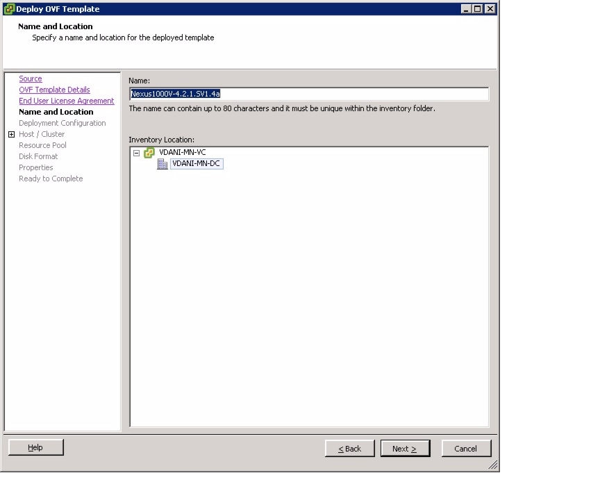
Step 6 ![]() Add the VSM name, choose the folder location within the inventory where it will reside, and click Next.
Add the VSM name, choose the folder location within the inventory where it will reside, and click Next.
The name for the VSM must be unique within the inventory folder and less than 80 characters.
The Deployment Configuration screen opens. See Figure B-5.
Figure B-5 Deployment Configuration Screen
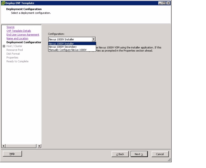
Step 7 ![]() From the Configuration drop-down list, choose Nexus 1000V Installer.
From the Configuration drop-down list, choose Nexus 1000V Installer.
This choice configures the primary VSM using the GUI setup dialog.
Step 8 ![]() Click Next.
Click Next.
The Host or Cluster screen opens.
Step 9 ![]() Choose the data center or cluster on which to install the VSM.
Choose the data center or cluster on which to install the VSM.
Step 10 ![]() Click Next.
Click Next.
The Datastore screen opens.
Step 11 ![]() Choose the datastore in which to store the file if one is available.
Choose the datastore in which to store the file if one is available.
On this page, you choose from datastores already configured on the destination cluster or host. The virtual machine configuration file and virtual disk files are stored on the datastore. Choose a datastore large enough to accommodate the virtual machine and all of its virtual disk files.
Step 12 ![]() Click Next.
Click Next.
The Disk Format screen opens.
Step 13 ![]() Choose the Thick provisioned disk format for storing virtual machine virtual disks, and click Next.
Choose the Thick provisioned disk format for storing virtual machine virtual disks, and click Next.
Table B-1 lists the available disk formats.
The Network Mapping screen opens. See Figure B-6.
Figure B-6 Network Mapping Screen

Step 14 ![]() In the Network Mapping screen, choose the networks (the control, management, and packet port groups) that are present in your inventory.
In the Network Mapping screen, choose the networks (the control, management, and packet port groups) that are present in your inventory.
Step 15 ![]() Click Next.
Click Next.
The Properties screen opens. See Figure B-7.
Figure B-7 Properties Screen
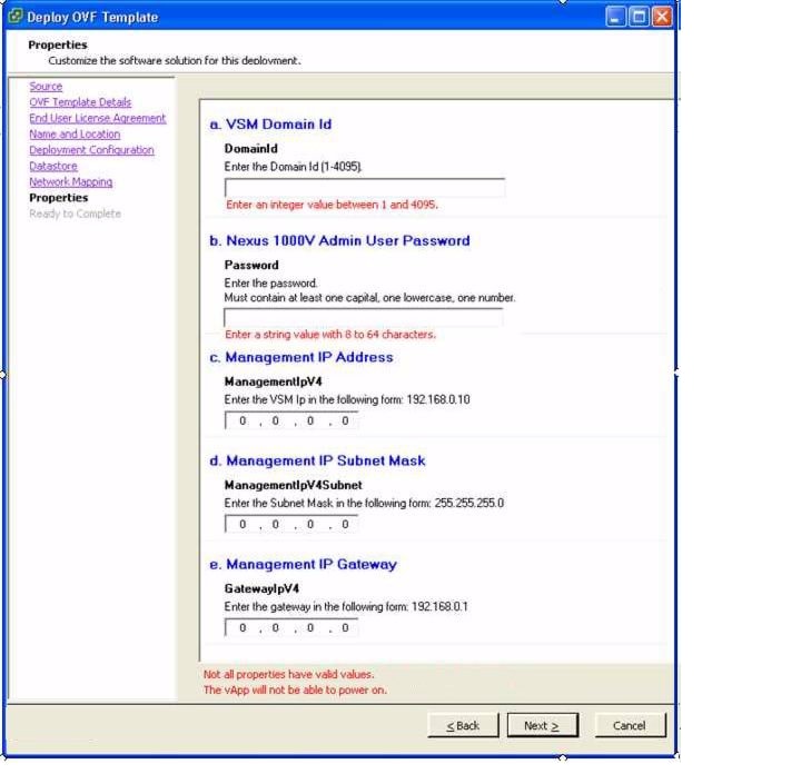
Step 16 ![]() Do one of the following:
Do one of the following:
•![]() If you are installing software on a primary VSM, specify the following properties for your primary VSM:
If you are installing software on a primary VSM, specify the following properties for your primary VSM:
–![]() VSM domain ID
VSM domain ID
–![]() Admin password
Admin password
–![]() Management IP address
Management IP address
–![]() Management IP subnet mask
Management IP subnet mask
–![]() Management IP gateway
Management IP gateway
•![]() If you are installing software on a secondary VSM, specify only the following properties for your secondary VSM (all other properties are acquired on synchronization with the primary VSM), and then click Next:
If you are installing software on a secondary VSM, specify only the following properties for your secondary VSM (all other properties are acquired on synchronization with the primary VSM), and then click Next:
–![]() VSM domain ID (use the same domain ID entered for the primary).
VSM domain ID (use the same domain ID entered for the primary).
–![]() Admin password (use the same password entered for the primary).
Admin password (use the same password entered for the primary).
Step 17 ![]() Click Next.
Click Next.
The Ready to Complete screen opens. See Figure B-8.
Figure B-8 Ready to Complete Screen

Step 18 ![]() If the configuration is correct, click Finish.
If the configuration is correct, click Finish.
A status bar displays as the VM installation progresses.
The Deployment Completed Successfully screen opens.
Step 19 ![]() Click Close.
Click Close.
You have completed installing the Cisco Nexus 1000V software.
Step 20 ![]() Right-click the VSM and choose Open Console.
Right-click the VSM and choose Open Console.
Step 21 ![]() Click the green arrow to power on the VSM.
Click the green arrow to power on the VSM.
Step 22 ![]() Enter the following command at the VSM prompt.
Enter the following command at the VSM prompt.
switch# configure terminal
switch(config)# setup
Step 23 ![]() Enter the HA role.
Enter the HA role.
If you do not specify a role, standalone is assigned by default.
This example shows the HA role as primary.
Enter HA role[standalone/primary/secondary]: primary
[#########################################] 100%
---- Basic System Configuration Dialog ----
This setup utility will guide you through the basic configuration of
the system. Setup configures only enough connectivity for management
of the system.
*Note: setup is mainly used for configuring the system initially,
when no configuration is present. So setup always assumes system
defaults and not the current system configuration values.
Press Enter at anytime to skip a dialog. Use ctrl-c at anytime
to skip the remaining dialogs.
Would you like to enter the basic configuration dialog (yes/no):
This example shows the HA role as secondary.
Enter HA role[standalone/primary/secondary]: secondary
Setting HA role to secondary will cause a system reboot. Are you sure (yes/no) ? :
Step 24 ![]() Do one of the following:
Do one of the following:
•![]() If you are setting up the primary/active VSM, go to Step 18.
If you are setting up the primary/active VSM, go to Step 18.
•![]() If you are setting up the secondary/standby VSM, then continue with the next step.
If you are setting up the secondary/standby VSM, then continue with the next step.
Step 25 ![]() If you have set up the VSM virtual machine (VM) to boot from the CD-ROM, and are installing the secondary VSM from the ISO image attached to your CD-ROM, remove the virtual CD-ROM now so that the VSM does not boot from the CD.
If you have set up the VSM virtual machine (VM) to boot from the CD-ROM, and are installing the secondary VSM from the ISO image attached to your CD-ROM, remove the virtual CD-ROM now so that the VSM does not boot from the CD.
This step is necessary if you have set up the VSM VM to boot from the CD-ROM before the hard drive.
Step 26 ![]() If you are setting up the secondary/standby VSM, when prompted to reboot the VSM, answer yes.
If you are setting up the secondary/standby VSM, when prompted to reboot the VSM, answer yes.
The secondary VSM VM is rebooted and brought up in standby mode.
The password on the secondary VSM is synchronized with the password on the active/primary VSM.
Any configuration made on the active/primary VSM is now automatically synchronized with the standby.
This example show the system rebooting when the HA role is set to secondary.
Setting HA role to secondary will cause a system reboot. Are you sure (yes/no) ? :y
[########################################] 100%
HA mode set to secondary. Rebooting now...
You have completed this procedure for the secondary VSM.
Step 27 ![]() Enter yes to enter the basic configuration dialog.
Enter yes to enter the basic configuration dialog.
Would you like to enter the basic configuration dialog (yes/no): yes
Step 28 ![]() Enter no to create another Login account.
Enter no to create another Login account.
Create another login account (yes/no) [n]: no
Step 29 ![]() Enter no to configure a read-only SNMP community string.
Enter no to configure a read-only SNMP community string.
Configure read-only SNMP community string (yes/no) [n]: no
Step 30 ![]() Enter no to configure a read-write SNMP community string.
Enter no to configure a read-write SNMP community string.
Configure read-write SNMP community string (yes/no) [n]: no
Step 31 ![]() Enter a name for the switch.
Enter a name for the switch.
Enter the switch name: n1000v
Step 32 ![]() Enter yes to configure out-of-band management and then enter the mgmt0 IPv4 address and subnet mask.
Enter yes to configure out-of-band management and then enter the mgmt0 IPv4 address and subnet mask.
Continue with Out-of-band (mgmt0) management configuration? [yes/no] [y]: yes
Mgmt0 IPv4 address: 172.28.15.152
Mgmt0 IPv4 netmask: 255.255.255.0
Step 33 ![]() Enter yes to configure the default gateway.
Enter yes to configure the default gateway.
Configure the default-gateway: (yes/no) [y]: yes
IPv4 address of the default gateway : 172.23.233.1
Step 34 ![]() Enter no to configure advanced IP options.
Enter no to configure advanced IP options.
Configure Advanced IP options (yes/no)? [n]: no
Step 35 ![]() Enter yes to enable the Telnet service.
Enter yes to enable the Telnet service.
Enable the telnet service? (yes/no) [y]: yes
Step 36 ![]() Enter yes to enable the SSH service and then enter the key type and number of key bits.
Enter yes to enable the SSH service and then enter the key type and number of key bits.
For more information, see the document,Cisco Nexus 1000V Security Configuration Guide, Release 4.2(1)SV1(5.1).
Enable the ssh service? (yes/no) [y]: yes
Type of ssh key you would like to generate (dsa/rsa) : rsa
Number of  key bits <768-2048> : 1024
Step 37 ![]() Enter yes to enable the HTTP server.
Enter yes to enable the HTTP server.
Enable the http-server? (yes/no) [y]: yes
Step 38 ![]() Enter no to configure the NTP server.
Enter no to configure the NTP server.
Configure NTP server? (yes/no) [n]: no
Step 39 ![]() Enter yes to configure the SVS domain parameters and then enter the mode (L2 or L3), and the control and packet VLAN IDs.
Enter yes to configure the SVS domain parameters and then enter the mode (L2 or L3), and the control and packet VLAN IDs.
Configure svs domain parameters? (yes/no) [y]: yes
Enter SVS Control mode (L2 / L3) : L2
Enter control vlan <1-3967, 4048-4093> : 100
Enter packet vlan <1-3967, 4048-4093> : 101
Step 40 ![]() Enter yes to configure the VEM feature level and then enter 0 or 1.
Enter yes to configure the VEM feature level and then enter 0 or 1.
Vem feature level will be set to 4.2(1)SV1(5.1),
Do you want to reconfigure? (yes/no) [n] yes
Current vem feature level is set to 4.2(1)SV1(5.1)
You can change the feature level to:
vem feature level is set to the highest value possible
The system now summarizes the complete configuration and asks if you want to edit it.
The following configuration will be applied:
Switchname n1000v
interface Mgmt0
ip address 172.28.15.152 255.255.255.0
no shutdown
no telnet server enable
ssh key rsa 1024 force
ssh server enable
feature http-server
svs-domain
svs mode L2
control vlan 100
packet vlan 101
domain id 101
vlan 100
vlan 101
Step 41 ![]() Do one of the following:
Do one of the following:
•![]() If you do not want to edit the configuration enter no and continue with the next step.
If you do not want to edit the configuration enter no and continue with the next step.
•![]() If you want to edit the configuration, enter yes and return to Step 19 to revisit each command.
If you want to edit the configuration, enter yes and return to Step 19 to revisit each command.
Would you like to edit the configuration? (yes/no) [n]:no
Step 42 ![]() Enter yes to use and save this configuration, answer yes.
Enter yes to use and save this configuration, answer yes.
Use this configuration and save it? (yes/no) [y]: yes
[########################################] 100%
The new configuration is saved into nonvolatile storage.
Note ![]() You can use the setup routine to update the configuration done in Step 18 through Step 33 at any time by entering the setup command in EXEC mode. Once setup begins, press Enter to skip a command. Press Ctrl-C to skip the remaining commands.
You can use the setup routine to update the configuration done in Step 18 through Step 33 at any time by entering the setup command in EXEC mode. Once setup begins, press Enter to skip a command. Press Ctrl-C to skip the remaining commands.
Note ![]() If you are installing redundant VSMs, make sure that you configure the software on the primary VSM before installing the software on the secondary VSM.
If you are installing redundant VSMs, make sure that you configure the software on the primary VSM before installing the software on the secondary VSM.
Step 43 ![]() Create the SVS connection manually or go to the "Establishing the SVS Connection" section.
Create the SVS connection manually or go to the "Establishing the SVS Connection" section.
Establishing the SVS Connection
You can use this procedure to establish an SVS connection.
PROCEDURE
Step 1 ![]() Open the vSphere Client.
Open the vSphere Client.
The vSphere Client window opens. See Figure B-9.
Figure B-9 vSphere Client WIndow

Step 2 ![]() Choose the primary VSM.
Choose the primary VSM.
Step 3 ![]() Choose the Console tab.
Choose the Console tab.
Step 4 ![]() Enter the show svs connections command to confirm that there is not an SVS connection.
Enter the show svs connections command to confirm that there is not an SVS connection.
Step 5 ![]() Open a command window.
Open a command window.
The Comment window opens. See Figure B-10.
Figure B-10 Command Window
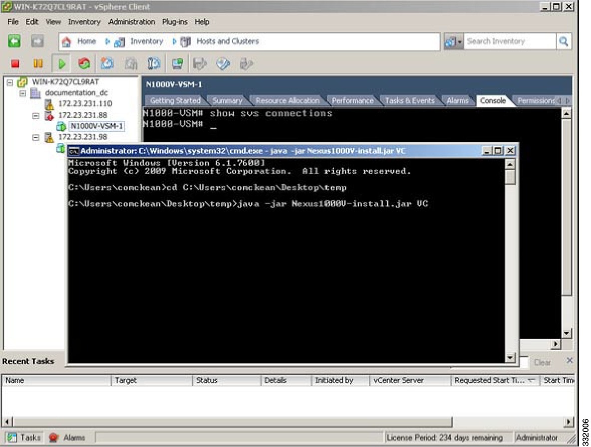
Step 6 ![]() Enter the java -jar Nexus1000V-install.jar VC command.
Enter the java -jar Nexus1000V-install.jar VC command.
The Enter vCenter Credentials screen opens. See Figure B-11.
Figure B-11 Enter vCenter Credentials Screen

Step 7 ![]() Enter the following vCenter credentials:
Enter the following vCenter credentials:
•![]() vCenter IP address
vCenter IP address
•![]() Secure HTTP port
Secure HTTP port
Port 443 is configured by default, but you can change the port if needed.
•![]() vCenter User ID (for a vCenter user with administrator-level privileges)
vCenter User ID (for a vCenter user with administrator-level privileges)
•![]() vCenter Password (for a vCenter user with administrator-level privileges)
vCenter Password (for a vCenter user with administrator-level privileges)
Step 8 ![]() Click Next.
Click Next.
The Enter VSM IP & Credentials screen opens. See Figure B-12.
Figure B-12 Enter VSM IP & Credentials Screen

Step 9 ![]() Enter the following VSM credentials:
Enter the following VSM credentials:
•![]() VSM IP Address
VSM IP Address
•![]() VSM Password
VSM Password
•![]() From the SVS Datacenter Name drop-down list, choose the data center.
From the SVS Datacenter Name drop-down list, choose the data center.
Step 10 ![]() Click Finish.
Click Finish.
The Summary screen opens. See Figure B-13.
Figure B-13 Summary Screen

Step 11 ![]() Click Close.
Click Close.
The Console window reappears. See Figure B-14.
Figure B-14 Console Window
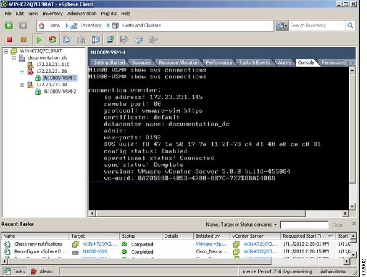
Step 12 ![]() In the vSphere Console window, enter the show svs connections command.
In the vSphere Console window, enter the show svs connections command.
The operational status is Connected.
You have completed establishing the SVS connection.
 Feedback