VSE Port Model
The Virtual Service Engine (VSE) ports on Cisco Nexus 1000VE are referred to as VSE Virtual Ports.
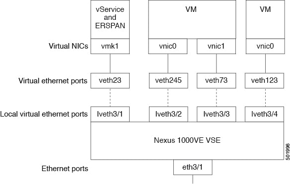
The following figure shows the VSE view of the network.
The documentation set for this product strives to use bias-free language. For the purposes of this documentation set, bias-free is defined as language that does not imply discrimination based on age, disability, gender, racial identity, ethnic identity, sexual orientation, socioeconomic status, and intersectionality. Exceptions may be present in the documentation due to language that is hardcoded in the user interfaces of the product software, language used based on RFP documentation, or language that is used by a referenced third-party product. Learn more about how Cisco is using Inclusive Language.
This chapter contains the following sections:
Information about Layer 2 Switching
The Virtual Service Engine (VSE) ports on Cisco Nexus 1000VE are referred to as VSE Virtual Ports.
The following figure shows the VSE view of the network.
The VSE maps together the following layers of ports:
There are two types of virtual NICs (vNICs). One vNIC represents a network interface on a Virtual Machine (VM), which emulates a physical port for the virtual host. The other vNIC is an internal port used by the hypervisor for management, iSCSI, and other network access. Each of these vNICs maps to a Virtual Ethernet port within the Cisco Nexus 1000VE.
A Virtual Ethernet Ports represents a port on the Cisco Nexus 1000VE Distributed Virtual Switch. The Cisco Nexus 1000VE has a flat space of vEth ports, 1...n. These vEth ports are what the virtual cable plugs into and are moved to the host that the VM is running on. Virtual Ethernet ports are assigned to port profiles.
The traffic egressing VSE Uplink port goes out through the Physical NICs added to the outside vDS.
The following figure shows the VSM view of the network.
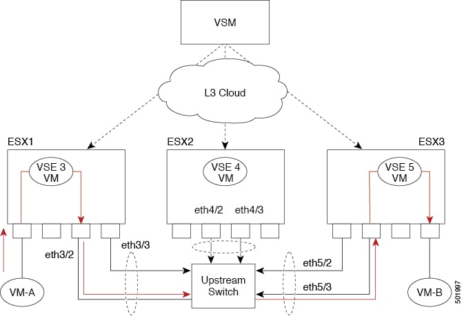
The Virtual Supervisor Module (VSM) has the following ports or interfaces:
Virtual Ethernet interfaces (vEths) can be associated with any of the following:
A virtual machine vNIC on the ESX host
A virtual machine kernel NIC on the ESX host
Physical Ethernet interfaces (Eths) correspond to the outside trunk interface of the VSEs.
The congestion related to high bandwidth and large numbers of users can be solved by assigning each device (for example, a server) to its own 10-, 100-, 1000-Mbps, or 10-Gigabit collision domain. Because each LAN port connects to a separate Ethernet collision domain, servers in a switched environment realize full bandwidth access.
Full duplex allows two stations to transmit and receive at the same time. 10/100-Mbps Ethernet usually operates in half-duplex mode, so that stations can either receive or transmit but not both. When packets can flow in both directions simultaneously, the effective Ethernet bandwidth doubles. 1/10-Gigabit Ethernet operates in full-duplex mode only.
Each LAN port can connect to a single workstation or server or to another device through which workstations or servers connect to the network.
To reduce signal degradation, each LAN port is considered to be an individual segment. When stations connected to different LAN ports need to communicate, frames are forwarded from one LAN port to the other at wire speed to ensure full bandwidth for each session.
To switch frames between LAN ports efficiently, a MAC address table is maintained. The MAC address of the sending network is associated with the LAN port on which it was received.
A VLAN is a switched network that is logically segmented by function, project team, or application, without regard to the physical locations of the users. VLANs have the same attributes of physical LANs, but you can group end stations even if they are not physically located on the same LAN segment.
Any switchport can belong to a VLAN, and unicast, broadcast, and multicast packets are forwarded and flooded only to end stations in that VLAN. Each VLAN is considered a logical network, and packets destined for stations that do not belong to the VLAN must be forwarded through a bridge or a router.
All ports, including the management port, are assigned to the default VLAN (VLAN1) when the device first comes up.
 Note |
Inter-Switch Link (ISL) trunking is not supported on the Cisco Nexus 1000VE. |
A control VLAN is used for communication between the VSM and the VSEs within a switch domain. The control interface is the first interface on the VSM.
A control VLAN is used for the following:
VSM configuration commands to each VSE and their responses.
VSE notifications to the VSM. For example, a VSE notifies the VSM of the attachment or detachment of ports to the Distributed Virtual Switch (DVS).
VSE NetFlow exports that are sent to the VSM, where they are forwarded to a NetFlow Collector.
VSM active to standby synchronization for high availability.
A management VLAN, which is used for system login and configuration, corresponds to the mgmt0 interface. The mgmt0 interface appears as the mgmt0 port on a Cisco switch and is assigned an IP address (IPv4). When the mgmt0 interface (default) is used for Layer 3 connectivity on the VSM, the management interface communicates with the VSEs and the VMware vCenter Server.
The management interface is the second interface on the VSM.
Similar to the control VLAN, a packet VLAN is used for communication between the VSM and the VSEs within a switch domain.
A packet VLAN is used to tunnel network protocol packets between the VSM and the VSEs.
The packet interface is the third interface on the VSM.
Private VLANs (PVLANs) are used to segregate Layer 2 ISP traffic and convey it to a single router interface. PVLANs achieve device isolation by applying Layer 2 forwarding constraints that allow end devices to share the same IP subnet while being Layer 2 isolated. The use of larger subnets reduces address management overhead.
 Feedback