Information About Q-in-Q Tunnels

A Q-in-Q VLAN tunnel enables a service provider to segregate the traffic of different customers in their infrastructure, while still giving the customer a full range of VLANs for their internal use by adding a second 802.1Q tag to an already tagged frame.

Business customers of service providers often have specific requirements for VLAN IDs and the number of VLANs to be supported. The VLAN ranges required by different customers in the same service-provider network might overlap, and traffic of customers through the infrastructure might be mixed. Assigning a unique range of VLAN IDs to each customer would restrict customer configurations and could easily exceed the VLAN limit of 4096 of the 802.1Q specification.


Note


Q-in-Q is supported on port channels. To configure a port channel as an asymmetrical link, all ports in the port channel must have the same tunneling configuration.


Using the 802.1Q tunneling feature, service providers can use a single VLAN to support customers who have multiple VLANs. Customer VLAN IDs are preserved and traffic from different customers is segregated within the service-provider infrastructure even when they appear to be on the same VLAN. The 802.1Q tunneling expands VLAN space by using a VLAN-in-VLAN hierarchy and tagging the tagged packets. A port configured to support 802.1Q tunneling is called a tunnel port. When you configure tunneling, you assign a tunnel port to a VLAN that is dedicated to tunneling. Each customer requires a separate VLAN, but that VLAN supports all of the customer’s VLANs.

Customer traffic tagged in the normal way with appropriate VLAN IDs come from an 802.1Q trunk port on the customer device and into a tunnel port on the service-provider edge switch. The link between the customer device and the edge switch is an asymmetric link because one end is configured as an 802.1Q trunk port and the other end is configured as a tunnel port. You assign the tunnel port interface to an access VLAN ID that is unique to each customer.


Note


Selective Q-in-Q tunneling is not supported. All frames entering the tunnel port are subjected to Q-in-Q tagging.


Figure 1. 802.1Q-in-Q Tunnel Ports


Packets that enter the tunnel port on the service-provider edge switch, which are already 802.1Q-tagged with the appropriate VLAN IDs, are encapsulated with another layer of an 802.1Q tag that contains a VLAN ID that is unique to the customer. The original 802.1Q tag from the customer is preserved in the encapsulated packet. Therefore, packets that enter the service-provider infrastructure are double-tagged.

The outer tag contains the customer’s access VLAN ID (as assigned by the service provider), and the inner VLAN ID is the VLAN of the incoming traffic (as assigned by the customer). This double tagging is called tag stacking, Double-Q, or Q-in-Q.

The following figure shows the differences between the untagged, tagged and double-tagged ethernet frames.

Figure 2. Untagged, 802.1Q-Tagged, and Double-Tagged Ethernet Frames


By using this method, the VLAN ID space of the outer tag is independent of the VLAN ID space of the inner tag. A single outer VLAN ID can represent the entire VLAN ID space for an individual customer. This technique allows the customer’s Layer 2 network to extend across the service provider network, potentially creating a virtual LAN infrastructure over multiple sites.


Note


Hierarchical tagging, that is multi-level dot1q tagging Q-in-Q, is not supported.


Native VLAN Hazard

When configuring 802.1Q tunneling on an edge switch, you must use 802.1Q trunk ports for sending out packets into the service-provider network. However, packets that go through the core of the service-provider network might be carried through 802.1Q trunks, ISL trunks, or nontrunking links. When 802.1Q trunks are used in these core switches, the native VLANs of the 802.1Q trunks must not match any native VLAN of the dot1q-tunnel port on the same switch because traffic on the native VLAN is not tagged on the 802.1Q transmitting trunk port.

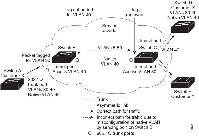
VLAN 40 is configured as the native VLAN for the 802.1Q trunk port from Customer X at the ingress edge switch in the service-provider network (Switch B). Switch A of Customer X sends a tagged packet on VLAN 30 to the ingress tunnel port of Switch B in the service-provider network that belongs to access VLAN 40. Because the access VLAN of the tunnel port (VLAN 40) is the same as the native VLAN of the edge-switch trunk port (VLAN 40), the 802.1Q tag is not added to the tagged packets that are received from the tunnel port. The packet carries only the VLAN 30 tag through the service-provider network to the trunk port of the egress-edge switch (Switch C) and is misdirected through the egress switch tunnel port to Customer Y.

The following figure shows the native VLAN hazard.

Figure 3. Native VLAN Hazard


A couple of ways to solve the native VLAN problem, are as follows:

  • Configure the edge switch so that all packets going out an 802.1Q trunk, including the native VLAN, are tagged by using the vlan dot1q tag native command. If the switch is configured to tag native VLAN packets on all 802.1Q trunks, the switch accepts untagged packets but sends only tagged packets.


    Note


    The vlan dot1q tag native command is a global command that affects the tagging behavior on all trunk ports.


  • Ensure that the native VLAN ID on the edge switch trunk port is not within the customer VLAN range. For example, if the trunk port carries traffic of VLANs 100 to 200, assign the native VLAN a number outside that range.

Information About Layer 2 Protocol Tunneling

Customers at different sites connected across a service-provider network need to run various Layer 2 protocols to scale their topology to include all remote sites, as well as the local sites. The Spanning Tree Protocol (STP) must run properly, and every VLAN should build a proper spanning tree that includes the local site and all remote sites across the service-provider infrastructure. Cisco Discovery Protocol (CDP) must be able to discover neighboring Cisco devices from local and remote sites, and the VLAN Trunking Protocol (VTP) must provide consistent VLAN configuration throughout all sites in the customer network.

You can configure the switch to allow multi-tagged BPDUs on a tunnel port. If you enable l2 protocol tunnel allow-double-tag, when a multi-tagged customer BPDU enters the tunnel port, the original 802.1Q tags from the customer traffic is preserved and an outer VLAN tag (customer’s access VLAN ID, as assigned by the service-provider) is added in the encapsulated packet. Therefore, BDPU packets that enter the service-provider infrastructure are multi tagged. When the BDPUs leave the service-provider network , the outer tag is removed and the original multi-tagged BDPU is sent to the customer network.

When protocol tunneling is enabled, edge switches on the inbound side of the service-provider infrastructure encapsulate Layer 2 protocol packets with a special MAC address and send them across the service-provider network. Core switches in the network do not process these packets, but forward them as normal packets. Bridge protocol data units (BPDUs) for CDP, STP, or VTP cross the service-provider infrastructure and are delivered to customer switches on the outbound side of the service-provider network. Identical packets are received by all customer ports on the same VLANs.

If protocol tunneling is not enabled on 802.1Q tunneling ports, remote switches at the receiving end of the service-provider network do not receive the BPDUs and cannot properly run STP, CDP, 802.1X, and VTP. When protocol tunneling is enabled, Layer 2 protocols within each customer’s network are totally separate from those running within the service-provider network. Customer switches on different sites that send traffic through the service-provider network with 802.1Q tunneling achieve complete knowledge of the customer’s VLAN.


Note


Layer 2 protocol tunneling works by tunneling BPDUs in the software. A large number of BPDUs that comes into the supervisor module cause the CPU load to go up. The load It is controlled by Control Plane Policing CoPP configured for packets marked as BPDU.


For example, the following figure shows Customer X has four switches in the same VLAN that are connected through the service-provider network. If the network does not tunnel BPDUs, the switches on the far ends of the network cannot properly run the STP, CDP, 802.1X, and VTP protocols.

Figure 4. Layer 2 Protocol Tunneling


In the preceding example, STP for a VLAN on a switch in Customer X, Site 1 will build a spanning tree on the switches at that site without considering convergence parameters based on Customer X’s switch in Site 2.

The following figure shows the resulting topology on the customer’s network when BPDU tunneling is not enabled.

Figure 5. Virtual Network Topology Without BPDU Tunneling


Guidelines and Limitations for Q-in-Q Tunneling

Q-in-Q tunnels and Layer 2 tunneling have the following configuration guidelines and limitations:

  • Switches in the service-provider network must be configured to handle the increase in MTU size due to Q-in-Q tagging.

  • Cisco Nexus 3500 Series switches do not support configuring Q-in-Q Tunneling on Cisco NX-OS Release 7.0(3)I7(2) and the previous releases.

  • Cisco Nexus 3500 Series switches do not support Q-in-Q tunneling. However they forward Q-in-Q traffic.

  • Selective Q-in-Q tunneling is not supported. All frames that enter the tunnel port will be subject to Q-in-Q tagging.

  • MAC address learning for Q-in-Q tagged packets is based on the outer VLAN (Service Provider VLAN) tag. Packet forwarding issues may occur in deployments where a single MAC address is used across multiple inner (customer) VLANs.

  • Layer 3 and higher parameters cannot be identified in tunnel traffic (for example, Layer 3 destination and source addresses). Tunneled traffic cannot be routed.

  • You should use MAC address-based frame distribution.

  • You cannot configure the 802.1Q tunneling feature on ports that are configured to support private VLANs. Private VLAN are not required in these deployments.

  • CDP must be explicitly disabled, as needed, on the dot1Q tunnel port.

  • You must disable IGMP snooping on the tunnel VLANs.

  • You should run the vlan dot1Q tag native command to maintain the tagging on the native VLAN and drop untagged traffic to prevent native VLAN misconfigurations.

  • You must manually configure the 802.1Q interfaces to be edge ports.

  • Dot1x tunneling is not supported.

  • Cisco Nexus 3400 platform switches do not support Q-in-Q.

Configuring Q-in-Q Tunnels and Layer 2 Protocol Tunneling

Creating a 802.1Q Tunnel Port

You create the dot1q-tunnel port using the switchport mode command.


Note


You must set the 802.1Q tunnel port to an edge port with the spanning-tree port type edge command. The VLAN membership of the port is changed when you enter the switchport access vlan vlan-id command.

You should disable IGMP snooping on the access VLAN allocated for the dot1q-tunnel port to allow multicast packets to traverse the Q-in-Q tunnel.


Before you begin

You must first configure the interface as a switchport.

SUMMARY STEPS

  1. switch# configure terminal
  2. switch(config)# interface ethernet slot/port
  3. switch(config-if)# switchport
  4. switch(config-if)# [no] switchport mode dot1q-tunnel
  5. switch(config-if)# [no] l2protocol tunnel allow-double-tag
  6. switch(config-if)# exit
  7. (Optional) switch(config)# show dot1q-tunnel [interface if-range]
  8. (Optional) switch(config)# copy running-config startup-config

DETAILED STEPS

  Command or Action Purpose

Step 1

switch# configure terminal

Enters global configuration mode.

Step 2

switch(config)# interface ethernet slot/port

Specifies an interface to configure, and enters interface configuration mode.

Step 3

switch(config-if)# switchport

Sets the interface as a Layer 2 switching port.

Step 4

switch(config-if)# [no] switchport mode dot1q-tunnel

Creates an 802.1Q tunnel on the port. The port will go down and reinitialize (port flap) when the interface mode is changed. BPDU filtering is enabled and CDP is disabled on tunnel interfaces.

Step 5

switch(config-if)# [no] l2protocol tunnel allow-double-tag

Enable or disable multi tagged BDPU support.

Step 6

switch(config-if)# exit

Exits interface configuration mode.

Step 7

(Optional) switch(config)# show dot1q-tunnel [interface if-range]

(Optional)

Displays all ports that are in dot1q-tunnel mode. Optionally you can specify an interface or range of interfaces to display.

Step 8

(Optional) switch(config)# copy running-config startup-config

(Optional)

Saves the change persistently through reboots and restarts by copying the running configuration to the startup configuration.

Example

This example shows how to create an 802.1Q tunnel port:

switch# configure terminal 
switch(config)# interface ethernet 7/1 
switch(config-if)# switchport 
switch(config-if)# switchport mode dot1q-tunnel 
switch(config-if)# exit 
switch(config)# exit 
switch# show dot1q-tunnel 

Enabling the Layer 2 Protocol Tunnel

You can enable protocol tunneling on the 802.1Q tunnel port.

SUMMARY STEPS

  1. switch# configure terminal
  2. switch(config)# interface ethernet slot/port
  3. switch(config)# switchport
  4. switch(config-if)# switchport mode dot1q-tunnel
  5. switch(config-if)# [no] l2protocol tunnel [cdp | stp | vtp]
  6. switch(config-if)# exit
  7. (Optional) switch(config)# copy running-config startup-config

DETAILED STEPS

  Command or Action Purpose

Step 1

switch# configure terminal

Enters global configuration mode.

Step 2

switch(config)# interface ethernet slot/port

Specifies an interface to configure, and enters interface configuration mode.

Step 3

switch(config)# switchport

Sets the interface as a Layer 2 switching port.

Step 4

switch(config-if)# switchport mode dot1q-tunnel

Creates an 802.1Q tunnel on the port.

Step 5

switch(config-if)# [no] l2protocol tunnel [cdp | stp | vtp]

Enables Layer 2 protocol tunneling. Optionally, you can enable CDP, STP, or VTP tunneling.

Step 6

switch(config-if)# exit

Exits interface configuration mode.

Step 7

(Optional) switch(config)# copy running-config startup-config

(Optional)

Saves the change persistently through reboots and restarts by copying the running configuration to the startup configuration.

Example

This example shows how to enable protocol tunneling on an 802.1Q tunnel port:

switch# configure terminal 
switch(config)# interface ethernet 7/1 
switch(config-if)# switchport 
switch(config-if)# switchport mode dot1q-tunnel 
switch(config-if)# l2protocol tunnel stp 
switch(config-if)# exit 
switch(config)# exit 

Configuring Thresholds for Layer 2 Protocol Tunnel Ports

You can specify the port drop and shutdown value for a Layer 2 protocol tunneling port.

SUMMARY STEPS

  1. switch# configure terminal
  2. switch(config)# interface ethernet slot/port
  3. switch(config-if)# switchport
  4. switch(config-if)# switchport mode dot1q-tunnel
  5. switch(config-if)# [no] l2protocol tunnel drop-threshold [cdp | stp | vtp]
  6. switch(config-if)# [no] l2protocol tunnel shutdown-threshold [cdp | stp | vtp]
  7. switch(config-if)# exit
  8. (Optional) switch(config)# copy running-config startup-config

DETAILED STEPS

  Command or Action Purpose

Step 1

switch# configure terminal

Enters global configuration mode.

Step 2

switch(config)# interface ethernet slot/port

Specifies an interface to configure, and enters interface configuration mode.

Step 3

switch(config-if)# switchport

Sets the interface as a Layer 2 switching port.

Step 4

switch(config-if)# switchport mode dot1q-tunnel

Creates an 802.1Q tunnel on the port.

Step 5

switch(config-if)# [no] l2protocol tunnel drop-threshold [cdp | stp | vtp]

Specifies the maximum number of packets that can be processed on an interface before being dropped. Optionally, you can specify CDP, STP, or VTP. Valid values for the packets are from 1 to 4096.

The no form of this command resets the threshold values to 0 and disables the drop threshold.

Step 6

switch(config-if)# [no] l2protocol tunnel shutdown-threshold [cdp | stp | vtp]

Specifies the maximum number of packets that can be processed on an interface. When the number of packets is exceeded, the port is put in error-disabled state. Optionally, you can specify the Cisco Discovery Protocol (CDP), Spanning Tree Protocol (STP), or VLAN Trunking Protocol (VTP). Valid values for the packets is from 1 to 4096.

Step 7

switch(config-if)# exit

Exits interface configuration mode.

Step 8

(Optional) switch(config)# copy running-config startup-config

(Optional)

Saves the change persistently through reboots and restarts by copying the running configuration to the startup configuration.

Example

This example shows how to configure a threshold for a Layer 2 protocol tunnel port:

switch# configure terminal
switch(config)# interface ethernet 7/1
switch(config-if)# switchport
switch(config-if)# switchport mode dot1q-tunnel
switch(config)# l2protocol tunnel drop-threshold 3000
switch(config)# l2protocol tunnel shutdown-threshold 3000
switch(config)# exit
switch# copy running-config startup-config

Configuring VLAN Mapping for Selective Q-in-Q on a 802.1Q Tunnel Port

To configure VLAN mapping for selective Q-in-Q on a 802.1Q tunnel port, complete the following steps.


Note


You cannot configure one-to-one mapping and selective Q-in-Q on the same interface.


SUMMARY STEPS

  1. switch# configure terminal
  2. switch(config)# interface interface-id
  3. switch(config-if)# switchport mode dot1q-tunnel
  4. switch(config-if)# switchport vlan mapping vlan-id-range dot1q-tunnel outer vlan-id
  5. switch(config-if)# exit
  6. switch# show interfaces interface-id vlan mapping
  7. switch# copy running-config startup-config

DETAILED STEPS

  Command or Action Purpose

Step 1

switch# configure terminal

Enters global configuration mode.

Step 2

switch(config)# interface interface-id

Enters interface configuration mode for the interface connected to the service provider network. You can enter a physical interface or an EtherChannel port channel.

Step 3

switch(config-if)# switchport mode dot1q-tunnel

Configure the interface as a tunnel port.

Step 4

switch(config-if)# switchport vlan mapping vlan-id-range dot1q-tunnel outer vlan-id

Enters the VLAN IDs to be mapped:

  • vlan-id-range—The customer VLAN ID range (C-VLAN) entering the switch from the customer network. The range is from 1 to 4094. You can enter a string of VLAN-IDs.

  • outer vlan-id—Enter the outer VLAN ID (S-VLAN) of the service provider network. The range is from 1 to 4094.

Step 5

switch(config-if)# exit

Exits the configuration mode.

Step 6

switch# show interfaces interface-id vlan mapping

Verifies the configuration.

Step 7

switch# copy running-config startup-config

(Optional) Saves your entries in the configuration file.

Use the no switchport vlan mapping vlan-id-range dot1q-tunnel outer vlan-id command to remove the VLAN mapping configuration.

The following example shows how to drop all VLANs other than the configured mapping and allowed VLANs.


switch(config)# interface port-channel201 
switch(config-if)# switchport vlan mapping dot1q-tunnel allowed-vlan 201-204
switch(config-if)# switchport vlan mapping 300-400 dot1q-tunnel 500 
switch(config-if)# spanning-tree port type edge trunk
switch(config-if)# spanning-tree bpdufilter enable
switch(config-if)# vpc 201

Verifying the Q-in-Q Configuration

Use the following command to verify the Q-in-Q tunnel and Layer 2 protocol tunneling configuration information:

Command Purpose

clear l2protocol tunnel counters [interface if-range ]

Clears all the statistics counters. If no interfaces are specified, the Layer 2 protocol tunnel statistics are cleared for all interfaces.

show dot1q-tunnel [interface if-range]

Displays a range of interfaces or all interfaces that are in dot1q-tunnel mode.

show l2protocol tunnel [interface if-range | vlan vlan-id]

Displays Layer 2 protocol tunnel information for a range of interfaces or all dot1q-tunnel interfaces that are part of a specified VLAN or all interfaces.

show l2protocol tunnel summary

Displays a summary of all ports that have Layer 2 protocol tunnel configurations.

show running-config l2pt

Displays the current Layer 2 protocol tunnel running configuration.

Configuration Example for Q-in-Q and Layer 2 Protocol Tunneling

This example shows a service provider switch that is configured to process Q-in-Q for traffic coming in on Ethernet 7/1. A Layer 2 protocol tunnel is enabled for STP BPDUs. The customer is allocated VLAN 10 (outer VLAN tag).

switch# configure terminal
Enter configuration commands, one per line. End with CNTL/Z.
switch(config)# vlan 10
switch(config-vlan)# no shutdown
switch(config-vlan)# vlan configuration 8
switch(config-vlan-config)# no ip igmp snooping
switch(config-vlan-config)# exit
switch(config-vlan)# exit
switch(config)# interface ethernet 7/1
switch(config-if)# switchport
switch(config-if)# switchport mode dot1q-tunnel
switch(config-if)# switchport access vlan 10
switch(config-if)# spanning-tree port type edge
switch(config-if)# l2protocol tunnel stp
switch(config-if)# no shutdown
switch(config-if)# exit
switch(config)# exit
switch#

Feature History for Q-in-Q Tunnels and Layer 2 Protocol Tunneling

Table 1. Feature History for Q-in-Q Tunnels and Layer 2 Protocol Tunneling

Feature Name

Release

Feature Information

Q-in-Q VLAN Tunnels

6.0(2)U1(1)

This feature was introduced.

L2 Protocol Tunneling

6.0(2)U1(1)

This feature was introduced.