Configuring Layer 3 Interfaces

This chapter contains the following sections:

About Layer 3 Interfaces

Layer 3 interfaces forward IPv4 and IPv6 packets to another device using static or dynamic routing protocols. You can use Layer 3 interfaces for IP routing and inter-VLAN routing of Layer 2 traffic.

Routed Interfaces

You can configure a port as a Layer 2 interface or a Layer 3 interface. A routed interface is a physical port that can route IP traffic to another device. A routed interface is a Layer 3 interface only and does not support Layer 2 protocols, such as the Spanning Tree Protocol (STP).

All Ethernet ports are routed interfaces by default. You can change this default behavior with the CLI setup script.


Note


Cisco Nexus 3400-S Series switches have a Layer 2 default mode.


You can assign an IP address to the port, enable routing, and assign routing protocol characteristics to this routed interface.

You can also create a Layer 3 port channel from routed interfaces. For more information about port channels, see the “Configuring Port Channels” section.

Routed interfaces and subinterfaces support exponentially decayed rate counters. Cisco NX-OS tracks the following statistics with these averaging counters:

  • Input packets/sec

  • Output packets/sec

  • Input bytes/sec

  • Output bytes/sec

Subinterfaces

You can create virtual subinterfaces on a parent interface configured as a Layer 3 interface. A parent interface can be a physical port. 

Subinterfaces divide the parent interface into two or more virtual interfaces on which you can assign unique Layer 3 parameters such as IP addresses and dynamic routing protocols. The IP address for each subinterface should be in a different subnet from any other subinterface on the parent interface. 

You create a subinterface with a name that consists of the parent interface name (for example, Ethernet 2/1) followed by a period and then by a number that is unique for that subinterface. For example, you could create a subinterface for Ethernet interface 2/1 named Ethernet 2/1.1 where .1 indicates the subinterface. 

Cisco NX-OS enables subinterfaces when the parent interface is enabled. You can shut down a subinterface independent of shutting down the parent interface. If you shut down the parent interface, Cisco NX-OS shuts down all associated subinterfaces as well. 

One use of subinterfaces is to provide unique Layer 3 interfaces to each virtual local area network (VLAN) supported by the parent interface. In this scenario, the parent interface connects to a Layer 2 trunking port on another device. You configure a subinterface and associate the subinterface to a VLAN ID using 802.1Q trunking. 

The following figure shows a trunking port from a switch that connects to router B on interface E 2/1. This interface contains three subinterfaces that are associated with each of the three VLANs carried by the trunking port. 

Figure 1. Subinterfaces for VLANs

Limitations for Subinterfaces

The following are the limitations for subinterfaces:

  • Statistics for subinterfaces are not supported.

VLAN Interfaces

A VLAN interface, or switch virtual interface (SVI), is a virtual routed interface that connects a VLAN on the device to the Layer 3 router engine on the same device. Only one VLAN interface can be associated with a VLAN, but you need to configure a VLAN interface for a VLAN only when you want to route between VLANs or to provide IP host connectivity to the device through a virtual routing and forwarding (VRF) instance that is not the management VRF. When you enable VLAN interface creation, Cisco NX-OS creates a VLAN interface for the default VLAN (VLAN 1) to permit remote switch administration. 

You must enable the VLAN network interface feature before you can see configure it. The system automatically takes a checkpoint prior to disabling the feature, and you can roll back to this checkpoint. See the Cisco Nexus 3400-S NX-OS System Management Configuration Guide  for information on rollbacks and checkpoints. 


Note


You cannot delete the VLAN interface for VLAN 1. 


You can route across VLAN interfaces to provide Layer 3 inter-VLAN routing by configuring a VLAN interface for each VLAN that you want to route traffic to and assigning an IP address on the VLAN interface. For more information about IP addresses and IP routing, see the Cisco Nexus 3400-S NX-OS Unicast Routing Configuration Guide

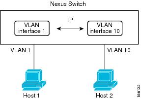
The following figure shows two hosts connected to two VLANs on a device. You can configure VLAN interfaces for each VLAN that allows Host 1 to communicate with Host 2 using IP routing between the VLANs. VLAN 1 communicates at Layer 3 over VLAN interface 1 and VLAN 10 communicates at Layer 3 over VLAN interface 10. 

Figure 2. Connecting Two VLANs with VLAN interfaces


Changing VRF Membership for an Interface

When you enter the vrf member command under an interface, you receive an alert regarding the deletion of interface configurations and to notify the clients/listeners (such as CLI-Server) to delete configurations with respect to the interface.

Entering the system vrf-member-change retain-l3-config command enables the retention of the Layer 3 configuration when the VRF member changes on the interface. It does this by sending notification to the clients/listeners to store (buffer) the existing configurations, delete the configurations from the old vrf context, and reapply the stored configurations under the new VRF context.


Note


When the system vrf-member-change retain-l3-config command is enabled, the Layer 3 configuration is not deleted and remains stored (buffered). When this command is not enabled (default mode), the Layer 3 configuration is not retained when the VRF member changes.


You can disable the retention of the Layer 3 configuration with the no system vrf-member-change retain-l3-config command. In this mode, the Layer 3 configuration is not retained when the VRF member changes.

Notes About Changing VRF Membership for an Interface

  • Momentary traffic loss may occur when changing the VRF name.

  • Only the configurations under the interface level are processed when the system vrf-member-change retain-l3-config command is enabled. You must manually process any configurations at the router level to accommodate routing protocols after a VRF change.

  • The system vrf-member-change retain-l3-config command supports interface level configurations with:

    • Layer 3 configurations maintained by the CLI Server, such as ip address and ipv6 address (secondary) and all OSPF/ISIS/EIGRP CLIs available under the interface configuration.

    • HSRP

    • DHCP Relay Agent CLIs, such as ip dhcp relay address [use-vrf] and ipv6 dhcp relay address [use-vrf] .

  • For DHCP:

    • As a best practice, the client and server interface VRF should be changed one at a time. Otherwise, the DHCP packets cannot be exchanged on the relay agent.

    • When the client and server are in different VRFs, use the ip dhcp relay address [use-vrf] command to exchange the DHCP packets in the relay agent over the different VRFs.

Loopback Interfaces

A loopback interface is a virtual interface with a single endpoint that is always up. Any packet transmitted over a loopback interface is immediately received by this interface. Loopback interfaces emulate a physical interface. You can configure up to 1024 loopback interfaces, numbered 0 to 1023.

You can use loopback interfaces for performance analysis, testing, and local communications. Loopback interfaces can act as a termination address for routing protocol sessions. This loopback configuration allows routing protocol sessions to stay up even if some of the outbound interfaces are down.

IP Unnumbered

The IP unnumbered feature enables the processing of IP packets on a point to point (p2p) interface without explicitly configuring a unique IP address on it. This approach borrows an IP address from another interface and conserves address space on point to point links.

Any interface which conforms to the point to point mode can be used as an IP unnumbered interface. The IP unnumbered feature is supported only on Ethernet interfaces and sub-interfaces. The borrowed interface can only be a loopback interface and is known as the numbered interface.

A loopback interface is ideal as a numbered interface in that it is always functionally up. However, because loopback interfaces are local to a switch/router, the reachability of unnumbered interfaces first needs to be established through static routes or by using an interior gateway protocol, such as OSPF or ISIS.

Configuring IP unnumbered interfaces for port channels is not supported on Cisco Nexus 3400-S switches.

Configuring SVI unnumbered interfaces is not supported on Cisco Nexus 3400-S switches.

MAC-Embedded IPv6 Address

BGP allows an IPv4 prefix to be carried over an IPv6 next hop. The IPv6 next hop is leveraged to remove neighbor discovery (ND)-related traffic from the network. To do this , the MAC address is embedded in the IPv6 address. Such an address is called a MAC-embedded IPv6 (MEv6) address. The router extracts the MAC address directly from the MEv6 address instead of going through ND. Local interface and next-hop MAC addresses are extracted from the IPv6 addresses.

On MEv6-enabled IPv6 interfaces, the same MEv6-extracted MAC address is used for IPv4 traffic as well. MEv6 is supported on all Layer 3-capable interfaces except switch virtual interfaces (SVIs).


Important


When MEv6 is enabled on an interface, ping6 to the IPv6 link local address, OSPFv3, and BFDv6 are not supported on that interface.


High Availability

Layer 3 interfaces support stateful and stateless restarts. After the switchover, Cisco NX-OS applies the runtime configuration after the switchover.

Virtualization Support

Layer 3 interfaces support Virtual Routing and Forwarding instances (VRFs). VRFs exist within virtual device contexts (VDCs). By default, Cisco NX-OS places you in the default VDC and default VRF .


Note


You must assign an interface to a VRF before you configure the IP address for that interface.


Prerequisites for Layer 3 Interfaces

Layer 3 interfaces have the following prerequisites:

  • You are familiar with IP addressing and basic configuration. See the Cisco Nexus 3400-S NX-OS Unicast Routing Configuration Guide for more information about IP addressing.

Guidelines and Limitations for Layer 3 Interfaces

Layer 3 interfaces have the following configuration guidelines and limitations:

  • show commands with the internal keyword are not supported.

  • If you change a Layer 3 interface to a Layer 2 interface, Cisco NX-OS shuts down the interface, reenables the interface, and removes all configuration specific to Layer 3.

  • If you change a Layer 2 interface to a Layer 3 interface, Cisco NX-OS shuts down the interface, reenables the interface, and deletes all configuration specific to Layer 2.

  • The Dynamic Host Configuration Protocol (DHCP) option is not supported when configuring a subinterface on a port-channel interface.

  • When an IP unnumbered interface is configured, a loopback interface should be in the same VRF as the IP unnumbered interface.

  • An admin-shutdown command on a loopback interface that is a numbered interface does not bring down the IP unnumbered interface. This means that the routing protocols running over the IP unnumbered interface continue to be up.

  • Static routes running over the IP unnumbered interface should use pinned static routes.


    Note


    The IP unnumbered interface through which the route is resolved needs to be specified.


  • An IP unnumbered interface is supported only on physical and sub-interfaces.

  • Only loopback interfaces can use unnumbered interfaces as numbered interfaces.

  • OSPF over an IP unnumbered interface is supported.

  • ISIS over an IP unnumbered interface is supported.

  • BGP over a loopback interface with an IP unnumbered interface as an overlay interface is supported.

  • The default and non-default VRF is supported by IP unnumbered interfaces.

  • The switch has a limit of 16 user-defined MAC addresses (MEv6/static). Configuring beyond this limit might result in issues documented in CSCux84428.

  • Beginning Cisco NX-OS Release 9.3(2), you can configure a user-defined MAC address limit between the range of 16–256. However, this user-defined MAC address limit is not supported on Cisco Nexus 3400 Series switches.


Note


If you are familiar with the Cisco IOS CLI, be aware that the Cisco NX-OS commands for this feature might differ from the Cisco IOS commands that you would use.


Default Settings

The following table lists the default settings for Layer 3 interface parameters.

Table 1. Default Layer 3 Interface Parameters

Parameters

Default

Admin state

Shut

Configuring Layer 3 Interfaces

Configuring a Routed Interface

You can configure any Ethernet port as a routed interface.

SUMMARY STEPS

  1. configure terminal
  2. interface ethernet slot/port
  3. no switchport
  4. [ip address ip-address/length | ipv6 address ipv6-address/length]
  5. show interfaces
  6. no shutdown
  7. copy running-config startup-config

DETAILED STEPS

  Command or Action Purpose

Step 1

configure terminal

Example:

switch# configure terminal
switch(config)#

Enters global configuration mode.

Step 2

interface ethernet slot/port

Example:

switch(config)# interface ethernet 2/1
switch(config-if)#

Enters interface configuration mode.

Step 3

no switchport

Example:

switch(config-if)# no switchport

Configures the interface as a Layer 3 interface.

Step 4

[ip address ip-address/length | ipv6 address ipv6-address/length]

Example:

switch(config-if)# ip address 192.0.2.1/8

Example:

switch(config-if)# ipv6 address 2001:0DB8::1/8
  • Configures an IP address for this interface.

  • Configures an IPv6 address for this interface.

Step 5

show interfaces

Example:

switch(config-if)# show interfaces ethernet 2/1

(Optional) Displays the Layer 3 interface statistics.

Step 6

no shutdown

Example:

switch# 
switch(config-if)# int e2/1
switch(config-if)# no shutdown

(Optional) Clears the errors on the interfaces where policies correspond with hardware policies. This command allows policy programming to continue and the port to come up. If policies do not correspond, the errors are placed in an error-disabled policy state.

Step 7

copy running-config startup-config

Example:

switch(config)# copy running-config startup-config  

(Optional) Saves the configuration change.

Example

  • Use the medium command to set the interface medium to either point to point or broadcast.

Command

Purpose

medium {broadcast | p2p}

Example:

switch(config-if)# medium p2p medium p2p

Configures the interface medium as either point to point or broadcast.


Note


The default setting is broadcast , and this setting does not appear in any of the show commands. However, if you do change the setting to p2p , you will see this setting when you enter the show running config command.


  • Use the switchport command to convert a Layer 3 interface into a Layer 2 interface.

Command

Purpose

switchport

Example:

switch(config-if)# switchportswitchport

Configures the interface as a Layer 2 interface and deletes any configuration specific to Layer 3 on this interface.

  • This example shows how to configure a routed interface:

    switch# configure terminal
    switch(config)# interface ethernet 2/1
    switch(config-if)# no switchport
    switch(config-if)# ip address 192.0.2.1/8 
    switch(config-if)# copy running-config startup-config

    The default setting for interfaces is routed. If you want to configure an interface for Layer 2, enter the switchport command. Then, if you change a Layer 2 interface to a routed interface, enter the no switchport command.

Configuring a Subinterface on a Routed Interface

You can configure one or more subinterfaces on a routed interface made from routed interfaces.

Before you begin

Configure the parent interface as a routed interface.

See the “Configuring a Routed Interface” section.

SUMMARY STEPS

  1. configure terminal
  2. interface ethernet slot/port.number
  3. [ip address ip-address/length | ipv6 address ipv6-address/length]
  4. encapsulation dot1Q vlan-id
  5. show interfaces
  6. copy running-config startup-config

DETAILED STEPS

  Command or Action Purpose

Step 1

configure terminal

Example:

switch# configure terminal
switch(config)#

Enters global configuration mode.

Step 2

interface ethernet slot/port.number

Example:

switch(config)# interface ethernet 2/1.1
switch(config-subif)#

Creates a subinterface and enters subinterface configuration mode. The number range is from 1 to 4094.

Note


A subinterface greater than 511 is not supported on physical interfaces.

Step 3

[ip address ip-address/length | ipv6 address ipv6-address/length]

Example:

switch(config-subif)# ip address 192.0.2.1/8

Example:

switch(config-subif)# ipv6 address 2001:0DB8::1/8
  • Configures an IP address for this subinterface.

  • Configures an IPv6 address for this subinterface.

Step 4

encapsulation dot1Q vlan-id

Example:

switch(config-subif)# encapsulation dot1Q 33

Configures IEEE 802.1Q VLAN encapsulation on the subinterface. The range is from 2 to 4093.

Step 5

show interfaces

Example:

switch(config-subif)# show interfaces ethernet 2/1.1

(Optional) Displays the Layer 3 interface statistics.

Step 6

copy running-config startup-config

Example:

switch(config)# copy running-config startup-config  

(Optional) Saves the configuration change.

Example

  • This example shows how to create a subinterface:

    switch# configure terminal
    switch(config)# interface ethernet 2/1.1
    switch(config-if)# ip address 192.0.2.1/8 
    switch(config-if)# encapsulation dot1Q 33
    switch(config-if)# copy running-config startup-config
  • The output of the show interface eth command is enhanced for the subinterfaces as shown in the following :

    switch# show interface ethernet 1/2.1 
    Ethernet1/2.1 is down (Parent Interface Admin down)
    admin state is down, Dedicated Interface, [parent interface is Ethernet1/2]
    Hardware: 40000 Ethernet, address: 0023.ac67.9bc1 (bia 4055.3926.61d4)
    Internet Address is 10.10.10.1/24
    MTU 1500 bytes, BW 40000000 Kbit, DLY 10 usec
    reliability 255/255, txload 1/255, rxload 1/255
    Auto-mdix is turned off
    EtherType is 0x8100 
    L3 in Switched:
    	ucast: 0 pkts, 0 bytes - mcast: 0 pkts, 0 bytes
    L3 out Switched:
        ucast: 0 pkts, 0 bytes - mcast: 0 pkts, 0 bytes

Configuring a Subinterface on a Port-Channel Interface

You can configure one or more subinterfaces on a port-channel interface.


Note


Subinterfaces on a port-channel interface do not support multicast routing, router ACLs, QoS, policy-based routing (PBR), SPAN, or ERSPAN.


Before you begin

Configure the parent interface as a port-channel interface.

See the “Configuring Port Channels” chapter.

SUMMARY STEPS

  1. configure terminal
  2. interface port-channel channel-id.number
  3. [ip address ip-address/length | ipv6 address ipv6-address/length]
  4. encapsulation dot1Q vlan-id
  5. show interfaces
  6. copy running-config startup-config

DETAILED STEPS

  Command or Action Purpose

Step 1

configure terminal

Example:

switch# configure terminal
switch(config)#

Enters global configuration mode.

Step 2

interface port-channel channel-id.number

Example:

switch(config)# interface port-channel 100.1
switch(config-subif)#

Creates a subinterface and enters subinterface configuration mode.

Step 3

[ip address ip-address/length | ipv6 address ipv6-address/length]

Example:

switch(config-subif)# ip address 192.0.2.1/8

Example:

switch(config-subif)# ipv6 address 2001:0DB8::1/8
  • Configures an IP address for this subinterface.

  • Configures an IPv6 address for this subinterface.

Step 4

encapsulation dot1Q vlan-id

Example:

switch(config-subif)# encapsulation dot1Q 33

Configures IEEE 802.1Q VLAN encapsulation on the subinterface. The range is from 2 to 4093.

Step 5

show interfaces

Example:

switch(config-subif)# show interfaces ethernet 2/1.1

(Optional) Displays the Layer 3 interface statistics.

Step 6

copy running-config startup-config

Example:

switch(config)# copy running-config startup-config  

(Optional) Saves the configuration change.

Example

This example shows how to create a subinterface:


switch# configure terminal
switch(config)# interface port-channel 115.3
switch(config-subif)# ip address 141.143.101.2/24
switch(config-subif)# encapsulation dot1q 3
switch(config-subif)# copy running-config startup-config

Configuring a VLAN Interface

You can create VLAN interfaces to provide inter-VLAN routing.

SUMMARY STEPS

  1. configure terminal
  2. feature interface-vlan
  3. interface vlan number
  4. [ip address ip-address/length | ipv6 address ipv6-address/length]
  5. show interface vlan number
  6. no shutdown
  7. copy running-config startup-config

DETAILED STEPS

  Command or Action Purpose

Step 1

configure terminal

Example:

switch# configure terminal
switch(config)#

Enters configuration mode.

Step 2

feature interface-vlan

Example:

switch(config)# feature interface-vlan

Enables VLAN interface mode.

Step 3

interface vlan number

Example:

switch(config)# interface vlan 10
switch(config-if)#

Creates a VLAN interface. The number range is from 1 to 4094.

Step 4

[ip address ip-address/length | ipv6 address ipv6-address/length]

Example:

switch(config-if)# ip address 192.0.2.1/8

Example:

switch(config-if)# ipv6 address 2001:0DB8::1/8
  • Configures an IP address for this VLAN interface.

  • Configures an IPv6 address for this VLAN interface.

Step 5

show interface vlan number

Example:

switch(config-if)# show interface vlan 10

(Optional) Displays the Layer 3 interface statistics.

Step 6

no shutdown

Example:

switch(config)# int e3/1
switch(config)# no shutdown

(Optional) Clears the errors on the interfaces where policies correspond with hardware policies. This command allows policy programming to continue and the port to come up. If policies do not correspond, the errors are placed in an error-disabled policy state.

Step 7

copy running-config startup-config

Example:

switch(config-if)# copy running-config startup-config  

(Optional) Saves the configuration change.

Example

This example shows how to create a VLAN interface:

switch# configure terminal
switch(config)# feature interface-vlan
switch(config)# interface vlan 10
switch(config-if)# ip address 192.0.2.1/8
switch(config-if)# copy running-config startup-config

Enabling Layer 3 Retention During VRF Membership Change

The following steps enable the retention of the Layer 3 configuration when changing the VRF membership on the interface.

SUMMARY STEPS

  1. configure terminal
  2. system vrf-member-change retain-l3-config

DETAILED STEPS

  Command or Action Purpose

Step 1

configure terminal

Example:


switch# configure terminal
switch(config)# 

Enters configuration mode.

Step 2

system vrf-member-change retain-l3-config

Example:


switch(config)# system vrf-member-change retain-l3-config

Warning: Will retain L3 configuration when vrf member change on interface.

Enables Layer 3 configuration retention during VRF membership change.

Note

 
To disable the retention of the Layer 3 configuration, use the no system vrf-member-change retain-l3-config command.

Configuring a Loopback Interface

You can configure a loopback interface to create a virtual interface that is always up.

Before you begin

Ensure that the IP address of the loopback interface is unique across all routers on the network.

SUMMARY STEPS

  1. configure terminal
  2. interface loopback instance
  3. [ip address ip-address/length | ipv6 address ipv6-address/length]
  4. show interface loopback instance
  5. copy running-config startup-config

DETAILED STEPS

  Command or Action Purpose

Step 1

configure terminal

Example:

switch# configure terminal
switch(config)#

Enters configuration mode.

Step 2

interface loopback instance

Example:

switch(config)# interface loopback 0
switch(config-if)#

Creates a loopback interface. The range is from 0 to 1023.

Step 3

[ip address ip-address/length | ipv6 address ipv6-address/length]

Example:

switch(config-if)# ip address 192.0.2.1/8

Example:

switch(config-if)# ipv6 address 2001:0DB8::1/8
  • Configures an IP address for this interface.

  • Configures an IPv6 address for this interface.

Step 4

show interface loopback instance

Example:

switch(config-if)# show interface loopback 0

(Optional) Displays the loopback interface statistics.

Step 5

copy running-config startup-config

Example:

switch(config-if)# copy running-config startup-config  

(Optional) Saves the configuration change.

Example

This example shows how to create a loopback interface:

switch# configure terminal
switch(config)# interface loopback 0
switch(config-if)# ip address 192.0.2.1/8
switch(config-if)# copy running-config startup-config

Configuring IP Unnumbered on an Ethernet Interface

You can configure the IP unnumbered feature on an ethernet interface.

SUMMARY STEPS

  1. configure terminal
  2. interface ethernet slot/port
  3. medium p2p
  4. ip unnumbered type number

DETAILED STEPS

  Command or Action Purpose

Step 1

configure terminal

Example:

switch# configure terminal
switch(config)#

Enters global configuration mode.

Step 2

interface ethernet slot/port

Example:

switch(config)# interface ethernet 1/1
switch(config-if)#

Enters interface configuration mode.

Step 3

medium p2p

Example:

switch(config-if)# medium p2p

Configures the interface medium as point to point.

Step 4

ip unnumbered type number

Example:

switch(config-if)# ip unnumbered loopback 100

Enables IP processing on an interface without assigning an explicit IP address to the interface.

type and number specify another interface on which the router has an assigned IP address. The interface specified cannot be another unnumbered interface.

Note


type is limited to loopback .

Configuring OSPF for an IP Unnumbered Interface

You can configure OSPF for an IP unnumbered loopback interface.

SUMMARY STEPS

  1. configure terminal
  2. interface ethernet slot/port
  3. encapsulation dot1Q vlan-id
  4. medium p2p
  5. ip unnumbered type number
  6. (Optional) ip ospf authentication
  7. (Optional) ip ospf authentication-key password
  8. ip router ospf instance area area-number
  9. no shutdown
  10. interface loopback instance
  11. ip address ip-address/length
  12. ip router ospf instance area area-number

DETAILED STEPS

  Command or Action Purpose

Step 1

configure terminal

Example:

switch# configure terminal
switch(config)#

Enters global configuration mode.

Step 2

interface ethernet slot/port

Example:

switch(config)# interface ethernet 1/20.1
switch(config-if)#

Enters interface configuration mode.

Step 3

encapsulation dot1Q vlan-id

Example:

switch(config-if)# encapsulation dot1Q 100

Configures IEEE 802.1Q VLAN encapsulation on the subinterface. The range is from 2 to 4093.

Step 4

medium p2p

Example:

switch(config-if)# medium p2p

Configures the interface medium as point to point.

Step 5

ip unnumbered type number

Example:

switch(config-if)# ip unnumbered loopback 101

Enables IP processing on an interface without assigning an explicit IP address to the interface.

type and number specify another interface on which the router has an assigned IP address. The interface specified cannot be another unnumbered interface.

Note


type is limited to loopback .

Step 6

(Optional) ip ospf authentication

Example:

switch(config-if)# ip ospf authentication
(Optional)

Specifies the authentication type for interface.

Step 7

(Optional) ip ospf authentication-key password

Example:

switch(config-if)# ip ospf authentication 3 b7bdf15f62bbd250
(Optional)

Specifies the authentication password for OSPF authentication.

Step 8

ip router ospf instance area area-number

Example:

switch(config-if)#  ip router ospf 100 area 0.0.0.1

Configures routing process for IP on an interface and specifies an area.

Note


The ip router ospf command is required for both the unnumbered and the numbered interface.

Step 9

no shutdown

Example:

switch(config-if)# no shutdown

Brings up the interface (administratively).

Step 10

interface loopback instance

Example:

switch(config)# interface loopback 101

Creates a loopback interface. The range is from 0 to 1023.

Step 11

ip address ip-address/length

Example:

switch(config-if)#  192.168.101.1/32

Configures an IP address for the interface.

Step 12

ip router ospf instance area area-number

Example:

switch(config-if)#  ip router ospf 100 area 0.0.0.1

Configures routing process for IP on an interface and specifies an area.

Note


The ip router ospf command is required for both the unnumbered and the numbered interface.

Configuring ISIS for an IP Unnumbered Interface

You can configure ISIS for an IP unnumbered loopback interface.

SUMMARY STEPS

  1. configure terminal
  2. feature isis
  3. router isis area-tag
  4. net network-entity-title
  5. end
  6. interface ethernet slot/port
  7. encapsulation dot1Q vlan-id
  8. medium p2p
  9. ip unnumbered type number
  10. ip router isis area-tag
  11. no shutdown

DETAILED STEPS

  Command or Action Purpose

Step 1

configure terminal

Example:

switch# configure terminal
switch(config)#

Enters global configuration mode.

Step 2

feature isis

Example:

Switch(config)# feature isis

Enables ISIS.

Step 3

router isis area-tag

Example:

Switch(config)# router isis 100

Assigns a tag to an IS-IS process and enters router configuration mode.

Step 4

net network-entity-title

Example:

Switch(config-router)# net 49.0001.0100.0100.1001.00

Configures the network entity title (NET) on the device.

Step 5

end

Example:

Switch(config-router)# end

Exit router configuration mode.

Step 6

interface ethernet slot/port

Example:

switch(config)# interface ethernet 1/20.1

Enters interface configuration mode.

Step 7

encapsulation dot1Q vlan-id

Example:

switch(config-subif)# encapsulation dot1Q 100

Configures IEEE 802.1Q VLAN encapsulation on the subinterface. The range is from 2 to 4093.

Step 8

medium p2p

Example:

switch(config-subif)# medium p2p

Configures the interface medium as point to point.

Step 9

ip unnumbered type number

Example:

switch(config-if)# ip unnumbered loopback 101

Enables IP processing on an interface without assigning an explicit IP address to the interface.

type and number specify another interface on which the router has an assigned IP address. The interface specified cannot be another unnumbered interface.

Note


type is limited to loopback .

Step 10

ip router isis area-tag

Example:

switch(config-subif)# ip router isis 100

Enables ISIS on the unnumbered interface.

Step 11

no shutdown

Example:

switch(config-subif)# no shutdown

Brings up the interface (administratively).

Assigning an Interface to a VRF

You can add a Layer 3 interface to a VRF.

SUMMARY STEPS

  1. configure terminal
  2. interface interface-type number
  3. vrf member vrf-name
  4. ip address ip-prefix/length
  5. show vrf [vrf-name] interface interface-type number
  6. copy running-config startup-config

DETAILED STEPS

  Command or Action Purpose

Step 1

configure terminal

Example:

switch# configure terminal
switch(config)#

Enters configuration mode.

Step 2

interface interface-type number

Example:

switch(config)# interface loopback 0
switch(config-if)#

Enters interface configuration mode.

Step 3

vrf member vrf-name

Example:

switch(config-if)# vrf member RemoteOfficeVRF

Adds this interface to a VRF.

Step 4

ip address ip-prefix/length

Example:

switch(config-if)# ip address 192.0.2.1/16

Configures an IP address for this interface. You must do this step after you assign this interface to a VRF.

Step 5

show vrf [vrf-name] interface interface-type number

Example:

switch(config-vrf)# show vrf Enterprise interface loopback 0

(Optional) Displays VRF information.

Step 6

copy running-config startup-config

Example:

switch(config-if)# copy running-config startup-config  

(Optional) Saves the configuration change.

Example

This example shows how to add a Layer 3 interface to the VRF:

switch# configure terminal
switch(config)# interface loopback 0
switch(config-if)# vrf member RemoteOfficeVRF
switch(config-if)# ip address 209.0.2.1/16
switch(config-if)# copy running-config startup-config

Configuring a MAC-Embedded IPv6 Address

You can configure a MAC-embedded IPv6 (MEv6) address.

SUMMARY STEPS

  1. configure terminal
  2. interface type slot/port
  3. no switchport
  4. mac-address ipv6-extract
  5. ipv6 address ip-address/length
  6. ipv6 nd mac-extract [exclude nud-phase]
  7. (Optional) show ipv6 icmp interface type slot/port
  8. (Optional) copy running-config startup-config

DETAILED STEPS

  Command or Action Purpose

Step 1

configure terminal

Example:

switch# configure terminal
switch(config)#

Enters global configuration mode.

Step 2

interface type slot/port

Example:

switch(config)# interface ethernet 1/3
switch(config-if)#

Enters the interface configuration mode for the specified interface.

Step 3

no switchport

Example:

switch(config-if)# no switchport

Configures the interface as a Layer 3 interface and deletes any configuration specific to Layer 2 on this interface.

Note


To convert a Layer 3 interface back into a Layer 2 interface, use the switchport command.

Step 4

mac-address ipv6-extract

Example:

switch(config-if)# mac-address ipv6-extract

Extracts the MAC address embedded in the IPv6 address configured on the interface.

Note


The MEv6 configuration is currently not supported with the EUI-64 format of IPv6 address.

Step 5

ipv6 address ip-address/length

Example:

switch(config-if)# ipv6 address 2002:1::10/64

Configures an IPv6 address for this interface.

Step 6

ipv6 nd mac-extract [exclude nud-phase]

Example:

switch(config-if)# ipv6 nd mac-extract

Extracts the next-hop MAC address embedded in a next-hop IPv6 address.

The exclude nud-phase option blocks packets during the ND phase only. When the exclude nud-phase option is not specified, packets are blocked during both ND and neighbor unreachability detection (NUD) phases.

Step 7

(Optional) show ipv6 icmp interface type slot/port

Example:

switch(config-if)# show ipv6 icmp interface ethernet 1/3
(Optional)

Displays IPv6 Internet Control Message Protocol version 6 (ICMPv6) interface information.

Step 8

(Optional) copy running-config startup-config

Example:

switch(config-if)# copy running-config startup-config
(Optional)

Copies the running configuration to the startup configuration.

Example

This example shows how to configure a MAC-embedded IPv6 address with ND mac-extract enabled:

switch# configure terminal
switch(config)# interface ethernet 1/3
switch(config-if)# no switchport
switch(config-if)# mac-address ipv6-extract
switch(config-if)# ipv6 address 2002:1::10/64
switch(config-if)# ipv6 nd mac-extract
switch(config-if)# show ipv6 icmp interface ethernet 1/3
ICMPv6 Interfaces for VRF "default"
Ethernet1/3, Interface status: protocol-up/link-up/admin-up
  IPv6 address: 2002:1::10
  IPv6 subnet:  2002:1::/64
  IPv6 interface DAD state:  VALID
  ND mac-extract : Enabled
  ICMPv6 active timers:
      Last Neighbor-Solicitation sent: 00:01:39
      Last Neighbor-Advertisement sent: 00:01:40
      Last Router-Advertisement sent: 00:01:41
      Next Router-Advertisement sent in: 00:03:34
  Router-Advertisement parameters:
      Periodic interval: 200 to 600 seconds
      Send "Managed Address Configuration" flag: false
      Send "Other Stateful Configuration" flag: false
      Send "Current Hop Limit" field: 64
      Send "MTU" option value: 1500
      Send "Router Lifetime" field: 1800 secs
      Send "Reachable Time" field: 0 ms
      Send "Retrans Timer" field: 0 ms
      Suppress RA: Disabled
      Suppress MTU in RA: Disabled
  Neighbor-Solicitation parameters:
      NS retransmit interval: 1000 ms
  ICMPv6 error message parameters:
      Send redirects: true
      Send unreachables: false
  ICMPv6-nd Statisitcs (sent/received):
      RAs: 3/0, RSs: 0/0, NAs: 2/0, NSs: 7/0, RDs: 0/0
      Interface statistics last reset: never

This example shows how to configure a MAC-embedded IPv6 address with ND mac-extract (excluding NUD phase) enabled:

switch# configure terminal
switch(config)# interface ethernet 1/5
switch(config-if)# no switchport
switch(config-if)# mac-address ipv6-extract
switch(config-if)# ipv6 address 2002:2::10/64
switch(config-if)# ipv6 nd mac-extract exclude nud-phase
switch(config-if)# show ipv6 icmp interface ethernet 1/5
ICMPv6 Interfaces for VRF "default"
Ethernet1/5, Interface status: protocol-up/link-up/admin-up
  IPv6 address: 2002:2::10
  IPv6 subnet:  2002:2::/64
  IPv6 interface DAD state:  VALID
  ND mac-extract : Enabled (Excluding NUD Phase)
  ICMPv6 active timers:
      Last Neighbor-Solicitation sent: 00:06:45
      Last Neighbor-Advertisement sent: 00:06:46
      Last Router-Advertisement sent: 00:02:18
      Next Router-Advertisement sent in: 00:02:24
  Router-Advertisement parameters:
      Periodic interval: 200 to 600 seconds
      Send "Managed Address Configuration" flag: false
      Send "Other Stateful Configuration" flag: false
      Send "Current Hop Limit" field: 64
      Send "MTU" option value: 1500
      Send "Router Lifetime" field: 1800 secs
      Send "Reachable Time" field: 0 ms
      Send "Retrans Timer" field: 0 ms
      Suppress RA: Disabled
      Suppress MTU in RA: Disabled
  Neighbor-Solicitation parameters:
      NS retransmit interval: 1000 ms
  ICMPv6 error message parameters:
      Send redirects: true
      Send unreachables: false
  ICMPv6-nd Statisitcs (sent/received):
      RAs: 6/0, RSs: 0/0, NAs: 2/0, NSs: 7/0, RDs: 0/0
      Interface statistics last reset: never

Configuring a DHCP Client on an Interface

You can configure the DHCP client on an SVI, a management interface, or a physical Ethernet interface for IPv4 or IPv6 address

SUMMARY STEPS

  1. switch# configure terminal
  2. switch(config)# interface ethernet type slot/port | mgmt mgmt-interface-number | vlan vlan id
  3. switch(config-if)# [no] ipv6 address use-link-local-only
  4. switch(config-if)# [no] [ip | ipv6] address dhcp
  5. (Optional) switch(config)# copy running-config startup-config

DETAILED STEPS

  Command or Action Purpose

Step 1

switch# configure terminal

Enters global configuration mode.

Step 2

switch(config)# interface ethernet type slot/port | mgmt mgmt-interface-number | vlan vlan id

Creates a physical Ethernet interface, a management interface, or a VLAN interface.

The range of vlan id is from 1 to 4094.

Step 3

switch(config-if)# [no] ipv6 address use-link-local-only

Prepares for request to the DHCP server.

Note


This command is only required for an IPv6 address.

Step 4

switch(config-if)# [no] [ip | ipv6] address dhcp

Requests the DHCP server for an IPv4 or IPv6 address.

The no form of this command removes any address that was acquired.

Step 5

(Optional) switch(config)# copy running-config startup-config

(Optional)

Saves the change persistently through reboots and restarts by copying the running configuration to the startup configuration.

Example

This example shows how to configure the IP address of a DHCP client on an SVI:

switch# configure terminal
switch(config)# interface vlan 15
switch(config-if)# ip address dhcp

This example shows how to configure an IPv6 address of a DHCP client on a management interface:

switch# configure terminal
switch(config)# interface mgmt 0
switch(config-if)# ipv6 address use-link-local-only
switch(config-if)# ipv6 address dhcp

Configuring Hardware Forwarded IPv4/IPv6 Interface Statistics

The following are the supported object identifiers (OIDs) :

  • ipIfStatsInReceives

  • ipIfStatsOutTransmits

  • ipIfStatsOutOctets

  • ipIfStatsInOctets

  • ipIfStatsHCInReceives

  • ipIfStatsHCOutTransmits

  • ipIfStatsHCOutOctets

  • ipIfStatsHCInOctets

Hardware forwarded IP interface statistics feature has the following restrictions:

  • This feature does not work on a physical interface which has more than 7 sub-interfaces.

  • Specified ipIfStatsTable counters are only supported with front panel ethernet interfaces.

  • All object identifiers (OIDs) other than supported OIDs is set to zero in the ipIfStatsTable.

  • There is no option to clear or reset the counters.

  • Maximum number of supported L3-physical-interfaces per slice is 62.

To configure hardware forwarding ip statistics on a device, follow these steps:

SUMMARY STEPS

  1. configure terminal
  2. [no] hardware forwarding ip statistics
  3. copy running-config startup-config
  4. reload

DETAILED STEPS

  Command or Action Purpose

Step 1

configure terminal

Example:

switch# configure terminal
switch(config)#

Enters global configuration mode.

Step 2

[no] hardware forwarding ip statistics

Example:

switch(config)# hardware forwarding ip statistics

Configures hardware forwarded IPv4/IPv6 interface statistics.

Step 3

copy running-config startup-config

Example:

switch(config)# copy running-config startup-config

Saves this configuration.

Step 4

reload

Example:

switch(config)# reload

Reload the switch.

Verifying the Layer 3 Interfaces Configuration

To display the Layer 3 configuration, perform one of the following tasks:

Command

Purpose

show interface ethernet slot/port

Displays the Layer 3 interface configuration, status, and counters (including the 5-minute exponentially decayed moving average of inbound and outbound packet and byte rates).

show interface ethernet slot/port brief

Displays the Layer 3 interface operational status.

show interface ethernet slot/port capabilities

Displays the Layer 3 interface capabilities, including port type, speed, and duplex.

show interface ethernet slot/port description

Displays the Layer 3 interface description.

show interface ethernet slot/port status

Displays the Layer 3 interface administrative status, port mode, speed, and duplex.

show interface ethernet slot/port.number

Displays the subinterface configuration, status, and counters (including the f-minute exponentially decayed moving average of inbound and outbound packet and byte rates).

show interface port-channel channel-id.number

Displays the port-channel subinterface configuration, status, and counters (including the 5-minute exponentially decayed moving average of inbound and outbound packet and byte rates).

show interface loopback number

Displays the loopback interface configuration, status, and counters.

show interface loopback number brief

Displays the loopback interface operational status.

show interface loopback number description

Displays the loopback interface description.

show interface loopback number status

Displays the loopback interface administrative status and protocol status.

show interface vlan number

Displays the VLAN interface configuration, status, and counters.

show interface vlan number brief

Displays the VLAN interface operational status.

show interface vlan number description

Displays the VLAN interface description.

show interface vlan number status

Displays the VLAN interface administrative status and protocol status.

show ip interface brief

Displays interface address and interface status (numbered/unnumbered).

show ip route

Displays routes learned via OSPF or ISIS. (Includes addresses for best unicast and multicast next-hop.)

Monitoring the Layer 3 Interfaces

Use the following commands to display Layer 3 statistics:

Command

Purpose

load- interval {interval seconds {1 | 2 | 3}}

Cisco Nexus 3400-S devices set three different sampling intervals to bit-rate and packet-rate statistics.

The range for VLAN network interface is 60 to 300 seconds, and the range for Layer interfaces is 30 to 300 seconds.

show interface ethernet slot/port counters

Displays the Layer 3 interface statistics (unicast, multicast, and broadcast).

show interface ethernet slot/port counters brief

Displays the Layer 3 interface input and output counters.

show interface ethernet errors slot/port detailed [all]

Displays the Layer 3 interface statistics. You can optionally include all 32-bit and 64-bit packet and byte counters (including errors).

show interface ethernet errors slot/port counters errors

Displays the Layer 3 interface input and output errors.

show interface ethernet errors slot/port counters snmp

Displays the Layer 3 interface counters reported by SNMP MIBs.

show interface ethernet slot/port.number counters

Displays the subinterface statistics (unicast, multicast, and broadcast).

show interface port-channel channel-id.number counters

Displays the port-channel subinterface statistics (unicast, multicast, and broadcast).

show interface loopback number counters

Displays the loopback interface input and output counters (unicast, multicast, and broadcast).

show interface loopback number detailed [all]

Displays the loopback interface statistics. You can optionally include all 32-bit and 64-bit packet and byte counters (including errors).

show interface loopback number counters errors

Displays the loopback interface input and output errors.

show interface vlan number counters

Displays the VLAN interface input and output counters (unicast, multicast, and broadcast).

show interface vlan number counters detailed [all]

Displays the VLAN interface statistics. You can optionally include all Layer 3 packet and byte counters (unicast and multicast).

show interface vlan number counters snmp

Displays the VLAN interface counters reported by SNMP MIBs.

show interface subinterface counters

Displays the Layer 3 subinterface statistics.

show interface port-channel subintreface counters

Displays the port-channel subinterface statistics.


Note


SVI countersis not supported for VLAN-IDs greater than 1000.


Configuration Examples for Layer 3 Interfaces

This example shows how to configure Ethernet subinterfaces:

interface ethernet 2/1.10
description Layer 3
ip address 192.0.2.1/8

This example shows how to configure a loopback interface:

interface loopback 3
ip address 192.0.2.2/32
This example displays port-channel subinterface statistics:

Note


Beginning with Cisco NX-OS Release 9.3(4), Cisco Nexus 3408-S switch supports the following additional statistic counters:

  • IPV4 InPkts

  • IPV6 InPkts

  • IPV4 OutPkts

  • IPV6 OutPkts

  • IPV4 InOctets/Bytes

  • IPV6 InOctets/Bytes

  • IPV4 OutOctets/Bytes

  • IPV6 OutOctets/Bytes


switch#  show interface port-channel 20.1 counters 
----------------------------------------------------------------------------------
Port                                     InOctets                      InUcastPkts
----------------------------------------------------------------------------------
Po20.1                                          0                               0

----------------------------------------------------------------------------------
Port                                  InMcastPkts                      InBcastPkts
----------------------------------------------------------------------------------
Po20.1                                          0                               0

----------------------------------------------------------------------------------
Port                                 InIPv4Octets                       InIPv4Pkts
----------------------------------------------------------------------------------
Po20.1                                        599                            63494
----------------------------------------------------------------------------------
Port                                 InIPv6Octets                       InIPv6Pkts
----------------------------------------------------------------------------------
Po20.1                                          0                               0

----------------------------------------------------------------------------------
Port                                    OutOctets                     OutUcastPkts
----------------------------------------------------------------------------------
Po20.1                                          0                               0

----------------------------------------------------------------------------------
Port                                 OutMcastPkts                     OutBcastPkts
----------------------------------------------------------------------------------
Po20.1                                          0                               0

----------------------------------------------------------------------------------
Port                                OutIPv4Octets                      OutIPv4Pkts
----------------------------------------------------------------------------------
Po20.1                                        599                            63494

----------------------------------------------------------------------------------
Port                                OutIPv6Octets                      OutIPv6Pkts
----------------------------------------------------------------------------------
Po20.1                                          0                               0
switch#  sh int e1/4.1 counters 
----------------------------------------------------------------------------------
Port                                     InOctets                      InUcastPkts
----------------------------------------------------------------------------------
Eth1/4.1                                        0                              0
 
----------------------------------------------------------------------------------
Port                                  InMcastPkts                      InBcastPkts
----------------------------------------------------------------------------------
Eth1/4.1                                        0                              0
 
----------------------------------------------------------------------------------
Port                                 InIPv4Octets                       InIPv4Pkts
----------------------------------------------------------------------------------
Eth1/4.1                                      270                            28620
 
----------------------------------------------------------------------------------
Port                                 InIPv6Octets                       InIPv6Pkts
----------------------------------------------------------------------------------
Eth1/4.1                                        0                              0
 
----------------------------------------------------------------------------------
Port                                    OutOctets                     OutUcastPkts
----------------------------------------------------------------------------------
Eth1/4.1                                        0                              0
 
----------------------------------------------------------------------------------
Port                                 OutMcastPkts                     OutBcastPkts
----------------------------------------------------------------------------------
Eth1/4.1                                        0                              0
 
----------------------------------------------------------------------------------
Port                                OutIPv4Octets                      OutIPv4Pkts
----------------------------------------------------------------------------------
Eth1/4.1                                      270                            28620
 
----------------------------------------------------------------------------------
Port                                OutIPv6Octets                      OutIPv6Pkts
----------------------------------------------------------------------------------
Eth1/4.1                                        0                              0

Example of Changing VRF Membership for an Interface

  • Enable Layer 3 configuration retention when changing VRF membership.

    
    switch# configure terminal
    switch(config)# system vrf-member-change retain-l3-config
    
    Warning: Will retain L3 configuration when vrf member change on interface.
  • Verify Layer 3 retention.

    
    switch# show running-config | include vrf-member-change
    
    system vrf-member-change retain-l3-config
  • Configure the SVI interface with Layer 3 configuration as VRF "blue".

    
    switch# configure terminal
    switch(config)# show running-config interface vlan 2002
    
    interface Vlan2002
    description TESTSVI
    no shutdown
    mtu 9192
    vrf member blue
    no ip redirects
    ip address 192.168.211.2/27
    ipv6 address 2620:10d:c041:12::2/64
    ipv6 link-local fe80::1
    ip router ospf 1 area 0.0.0.0
    ipv6 router ospfv3 1 area 0.0.0.0
    hsrp version 2
    hsrp 2002
    preempt delay minimum 300 reload 600
    priority 110 forwarding-threshold lower 1 upper 110
    ip 192.168.211.1
    hsrp 2002 ipv6
    preempt delay minimum 300 reload 600
    priority 110 forwarding-threshold lower 1 upper 110
    ip 2620:10d:c041:12::1
    
  • Change the SVI interface VRF to "red".

    
    switch# configure terminal
    
    Enter configuration commands, one per line. End with CNTL/Z.
    switch(config)# interface vlan 2002
    switch(config-if)# vrf member red
    
    Warning: Retain-L3-config is on, deleted and re-added L3 config on interface Vlan2002
    
  • Verify SVI interface after VRF change.

    
    switch# configure terminal
    switch(config)# show running-config interface vlan 2002
    
    interface Vlan2002
    description TESTSVI
    no shutdown
    mtu 9192
    vrf member red
    no ip redirects
    ip address 192.168.211.2/27
    ipv6 address 2620:10d:c041:12::2/64
    ipv6 link-local fe80::1
    ip router ospf 1 area 0.0.0.0
    ipv6 router ospfv3 1 area 0.0.0.0
    hsrp version 2
    hsrp 2002
    preempt delay minimum 300 reload 600
    priority 110 forwarding-threshold lower 1 upper 110
    ip 192.168.211.1
    hsrp 2002 ipv6
    preempt delay minimum 300 reload 600
    priority 110 forwarding-threshold lower 1 upper 110
    ip 2620:10d:c041:12::1
    

Note


  • When changing the VRF, the Layer 3 configuration retention affects:

    • Physical Interface

    • Loopback Interface

    • SVI Interface

    • Sub-interface

    • Tunnel Interface

    • Port-Channel

  • When changing the VRF, the existing Layer 3 configuration is deleted and reapplied. All routing protocols, such as OSPF/ISIS/EIGRP/HSRP, go down in the old VRF and come up in the new VRF.

  • Direct/Local IPv4/IPv6 addresses are removed from the old VRF and installed in the new VRF.

  • Some traffic loss might occur during the VRF change.


Related Documents

Related Documents

Document Title

IP

Cisco Nexus 3400-S NX-OS Unicast Routing Configuration Guide

VLANs

Cisco Nexus 3400-S NX-OS Layer 2 Switching Configuration Guide