Configuring Traffic Storm Control

This chapter describes how to configure traffic storm control on the Cisco NX-OS device.

This chapter includes the following sections:

About Traffic Storm Control

A traffic storm occurs when packets flood the LAN, creating excessive traffic and degrading network performance. You can use the traffic storm control feature to prevent disruptions on Layer 2 ports by a broadcast, multicast, or unicast traffic storm on physical interfaces.

Traffic storm control (also called traffic suppression) allows you to monitor the levels of the incoming broadcast, multicast, and unicast traffic over a 1 second interval. During this interval, the traffic level, which is a percentage of the total available bandwidth of the port, is compared with the traffic storm control level that you configured. When the ingress traffic reaches the traffic storm control level that is configured on the port, traffic storm control drops the traffic until the interval ends.

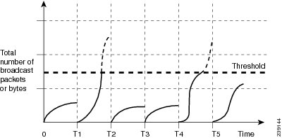
This table shows the broadcast traffic patterns on a Layer 2 interface over a given interval. In this example, traffic storm control occurs between times T1 and T2 and between T4 and T5. During those intervals, the amount of broadcast traffic exceeded the configured threshold.

Figure 1. Broadcast Suppression

The traffic storm control threshold numbers and the time interval allow the traffic storm control algorithm to work with different levels of granularity. A higher threshold allows more packets to pass through.

Traffic storm control on the Cisco Nexus 3400-S Series switches is implemented in the hardware. The traffic storm control circuitry monitors packets that pass from a Layer 2 interface to the switching bus. Using the Individual/Group bit in the packet destination address, the circuitry determines if the packet is unicast or broadcast, tracks the current count of packets within the 1 second interval, and filters out subsequent packets when a threshold is reached.

Traffic storm control uses a bandwidth-based method to measure traffic. You set the percentage of total available bandwidth that the controlled traffic can use. Because packets do not arrive at uniform intervals, the 1 second interval can affect the behavior of traffic storm control.

The following are examples of traffic storm control behavior:

  • If you enable broadcast traffic storm control, and broadcast traffic exceeds the level within the 1 second interval, traffic storm control drops all broadcast traffic until the end of the interval.

  • If you enable broadcast and multicast traffic storm control, and the combined broadcast and multicast traffic exceeds the level within the 1 second interval, traffic storm control drops all broadcast and multicast traffic until the end of the interval.

  • If you enable broadcast and multicast traffic storm control, and broadcast traffic exceeds the level within the 1 second interval, traffic storm control drops all broadcast and multicast traffic until the end of the interval.

  • If you enable broadcast and multicast traffic storm control, and multicast traffic exceeds the level within the 1 second interval, traffic storm control drops all broadcast and multicast traffic until the end of the interval.

By default, the Cisco Nexus 3400-S Series switches do not take a corrective action when the traffic exceeds the configured level.

Guidelines and Limitations for Traffic Storm Control

Traffic storm control has the following configuration guidelines and limitations:

  • You can configure traffic storm control on a port-channel interface.

  • Specify the traffic storm control level as a percentage of the total interface bandwidth:

    • The optional fraction of a level can be from 0 to 99.

    • 100 percent means no traffic storm control.

    • 0.0 percent suppresses all traffic.

  • For Cisco Nexus 3400-S Series switches, you can use the storm control CLI to specify bandwidth level as a percentage of port capacity.

  • Traffic storm control broadcast does not work for ARP traffic (ARP request) if you have configured a SVI for the VLAN on Cisco Nexus 3400-S Series switches.

  • For Cisco Nexus NFE2-enabled devices, you can use the storm control-cpu to control the number of ARP packets sent to the CPU.

  • Local link and hardware limitations prevent storm-control drops from being counted separately. Instead, storm-control drops are counted with other drops in the discards counter.

  • Because of hardware limitations and the method by which packets of different sizes are counted, the traffic storm control level percentage is an approximation. Depending on the sizes of the frames that make up the incoming traffic, the actual enforced level might differ from the configured level by several percentage points.

  • Due to a hardware limitation, the packet drop counter cannot distinguish between packet drops caused by a traffic storm and packet drops caused by other discarded input frames. This limitation can lead to the configured action being triggered even in the absence of a traffic storm.

  • Due to a hardware limitation, storm suppression packet statistics are not supported on uplink ports.

  • Due to a hardware limitation, storm suppression packet statistics do not include broadcast traffic on VLANs with an active switched virtual interface (SVI).

  • Due to a hardware limitation, ports on the same instance as the broadcast storm-control enabled port, can experience ARP request drops on VLANs with an active SVI.

  • Traffic storm control is not supported on FEX interfaces.

  • Traffic storm control is only for ingress traffic, specifically for unknown unicast, unknown multicast, and broadcast traffic.

  • When port channel members are error disabled due to a configured action, all individual member ports should be flapped to recover from the error disabled state.

  • Packet-based statistics are not supported for traffic storm control as the policer supports only byte-based statistics.

  • Traffic storm control is not supported for copy-to-CPU packets.

Default Settings for Traffic Storm Control

This table lists the default settings for traffic storm control parameters.

Table 1. Default Traffic Storm Control Parameters

Parameters

Default

Traffic storm control

Disabled

Threshold percentage

100

Configuring Traffic Storm Control

You can set the percentage of total available bandwidth that the controlled traffic can use.


Note

You must carve TCAM before setting the storm-control-cpu rate on a port channel.


SUMMARY STEPS

  1. configure terminal
  2. interface {ethernet slot/port | port-channel number}
  3. [no] storm-control {broadcast | multicast | unicast} level { level-value % }
  4. [no] storm-control [action { shutdown | trap }
  5. [no] storm-control-cpu arp rate
  6. exit
  7. (Optional) show running-config interface {ethernet slot/port | port-channel number}
  8. (Optional) copy running-config startup-config

DETAILED STEPS

  Command or Action Purpose
Step 1

configure terminal

Example:

switch# configure terminal
switch(config)#

Enters global configuration mode.

Step 2

interface {ethernet slot/port | port-channel number}

Example:

switch# interface ethernet 1/1
switch(config-if)#

Enters interface configuration mode.

Step 3

[no] storm-control {broadcast | multicast | unicast} level { level-value % }

Example:

switch(config-if)# storm-control unicast level 40

Configures traffic storm control for traffic on the interface. You can also configure bandwidth level as a percentage either of port capacity. The default state is disabled.

Step 4

[no] storm-control [action { shutdown | trap }

Example:

switch(config-if)# storm-control action trap

Generates an SNMP trap (defined in CISCO-PORT-STORM-CONTROL-MIB) and a syslog message or shuts down the port when the traffic storm control limit is reached.

  • Shutdown - Shuts down the port or puts it in the error-disable state.

  • trap - Generates an SNMP trap

Note 
The no form of this command removes the configured level or action. Although shutdown and trap actions can be specified independent of each other, the no form of storm-control action removes both actions.
Step 5

[no] storm-control-cpu arp rate

Example:

switch(config-if)# storm-control-cpu arp rate

Configures traffic storm control rate for arp packets entering a port channel. This rate is divided equally among the members of the port channel.

Step 6

exit

Example:

switch(config-if)# exit
switch(config)#

Exits interface configuration mode.

Step 7

(Optional) show running-config interface {ethernet slot/port | port-channel number}

Example:

switch(config)# show running-config interface ethernet 1/1
(Optional)

Displays the traffic storm control configuration.

Step 8

(Optional) copy running-config startup-config

Example:

switch(config)# copy running-config startup-config
(Optional)

Copies the running configuration to the startup configuration.

Verifying Traffic Storm Control Configuration

To display traffic storm control configuration information, perform one of the following tasks:

Command

Purpose

show running-config interface

Displays the traffic storm control configuration.

Monitoring Traffic Storm Control Counters

You can monitor the counters the Cisco NX-OS device maintains for traffic storm control activity.

Command

Purpose

show interface [ethernet slot/port | port-channel number] counters storm-control

Displays the traffic storm control counters.

Configuration Examples for Traffic Storm Control

The following example shows how to configure traffic storm control:

switch(config)# interface Ethernet1/1 
switch(config)# storm-control broadcast level 40 
switch(config)# storm-control multicast level 40 
switch(config)# storm-control unicast level 40