Configuring SPAN

This chapter describes how to configure an Ethernet switched port analyzer (SPAN) to analyze traffic between ports on Cisco NX-OS devices.

This chapter includes the following sections:

About SPAN

SPAN analyzes all traffic between source ports by directing the SPAN session traffic to a destination port with an external analyzer attached to it.

You can define the sources and destinations to monitor in a SPAN session on the local device.

SPAN Sources

The interfaces from which traffic can be monitored are called SPAN sources. Sources designate the traffic to monitor and whether to copy ingress (Rx), egress (Tx), or both directions of traffic. SPAN sources include the following:

  • Ethernet ports (but not subinterfaces)

  • Port channels

Characteristics of Source Ports

SPAN source ports have the following characteristics:

  • A port configured as a source port cannot also be configured as a destination port.

SPAN Destinations

SPAN destinations refer to the interfaces that monitor source ports. Destination ports receive the copied traffic from SPAN sources. SPAN destinations include the following:

  • Ethernet ports in either access or trunk mode

Characteristics of Destination Ports

SPAN destination ports have the following characteristics:

  • A port configured as a destination port cannot also be configured as a source port.

  • A destination port can be configured in only one SPAN session at a time.

  • Destination ports do not participate in any spanning tree instance. SPAN output includes bridge protocol data unit (BPDU) Spanning Tree Protocol hello packets.

SPAN Sessions

You can create SPAN sessions to designate sources and destinations to monitor.

See the Cisco Nexus 3400-S Series NX-OS Verified Scalability Guide for information on the number of supported SPAN sessions.

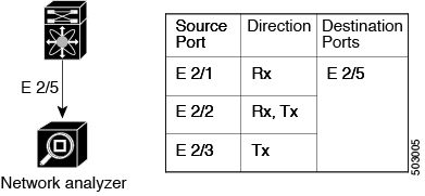
This figure shows a SPAN configuration. Packets on three Ethernet ports are copied to destination port Ethernet 2/5. Only traffic in the direction specified is copied.

Figure 1. SPAN Configuration

ACL TCAM Regions

You can change the size of the ACL ternary content addressable memory (TCAM) regions in the hardware. For information on the TCAM regions used by SPAN sessions, see the "Configuring IP ACLs" chapter of the Cisco Nexus 3400-S Series NX-OS Security Configuration Guide.

Licensing Requirements for SPAN

Product

License Requirement

Cisco NX-OS

SPAN requires no license. Any feature not included in a license package is bundled with the nx-os image and is provided at no extra charge to you. For a complete explanation of the Cisco NX-OS licensing scheme, see the Cisco NX-OS Licensing Guide.

Prerequisites for SPAN

SPAN has the following prerequisites:

  • You must first configure the ports on each device to support the desired SPAN configuration. For more information, see the Cisco Nexus 3400-S Series NX-OS Interfaces Configuration Guide.

Guidelines and Limitations for SPAN


Note


For scale information, see the release-specific Cisco Nexus 3400-S NX-OS Verified Scalability Guide.


SPAN has the following configuration guidelines and limitations:

  • All SPAN replication is performed in the hardware. The supervisor CPU is not involved.

  • In SPAN sessions, destination as a Port channel is not supported.

  • You can configure a SPAN session on the local device only.

  • Configuring two SPAN or ERSPAN sessions on the same source interface with only one filter is not supported. If the same source is used in multiple SPAN or ERSPAN sessions, either all the sessions must have different filters or no sessions should have filters.

  • For SPAN session limits, see the Cisco Nexus 3400-s Series NX-OS Verified Scalability Guide.

  • You can configure only one destination port in a SPAN session.

  • Interfaces configured as part of one SPAN/ERSPAN session as source interfaces cannot be used in other SPAN/ERSPAN sessions.

  • A destination port can be configured in only one SPAN session at a time.

  • You cannot configure a port as both a source and destination port.

  • Enabling UniDirectional Link Detection (UDLD) on the SPAN source and destination ports simultaneously is not supported. If UDLD frames are expected to be captured on the source port of such SPAN session, disable UDLD on the destination port of the SPAN session.

  • SPAN is not supported for management ports.

  • Statistics are not support for the filter access group.

  • SPAN is supported in Layer 3 mode; however, SPAN is not supported on Layer 3 subinterfaces or Layer 3 port-channel subinterfaces.

  • When you filter a monitor session, make sure that the access-group specified must be a VACL, or VLAN access-map and not a regular ACL for filtering purpose.

  • When a SPAN session contains source ports that are monitored in the transmit or transmit and receive direction, packets that these ports receive might be replicated to the SPAN destination port even though the packets are not actually transmitted on the source ports. Some examples of this behavior on source ports are as follows:

    • Traffic that results from flooding

    • Broadcast traffic

  • Cisco NX-OS does not span Link Layer Discovery Protocol (LLDP) or Link Aggregation Control Protocol (LACP) packets when the source interface is not a host interface port channel.

  • When using shut/no shut destination port , local span will stop working. As a workaround, shut/no shut the span session can recover it.

  • SPAN source or destination is supported on any port.

  • The cyclic redundancy check (CRC) is recalculated for the truncated packet.

  • Tx SPAN packets are truncated to 180 Bytes (Rx SPAN mirrors the whole packets).

  • The following SPAN functions are not supported:

    • IPv6 ACL filter (Tx)

    • Source VLAN Tx/Rx

    • VLAN filter Tx/Rx

    • ACL filter SPAN Tx (v4, v6)

    • CPU source (In-band SPAN)

    • Same source in multiple SPAN

    • SPAN PFC packets

    • Port-channel as destination (local or ERSPAN)

    • Source port sub-interface

Default Settings for SPAN

The following table lists the default settings for SPAN parameters.

Parameters Default
SPAN sessions Created in the shut state

Configuring SPAN

Configuring a SPAN Session

You can configure a SPAN session on the local device only. By default, SPAN sessions are created in the shut state.


Note


For bidirectional traditional sessions, you can configure the sessions without specifying the direction of the traffic.

Before you begin

You must configure the destination ports in access or trunk mode. For more information, see the Cisco Nexus 3400-S Series NX-OS Interfaces Configuration Guide.

SUMMARY STEPS

  1. configure terminal
  2. interface interface slot/port
  3. switchport
  4. switchport monitor
  5. (Optional) Repeat Steps 2 through 4 to configure monitoring on additional SPAN destinations.
  6. no monitor session session-number
  7. monitor session session-number [shut]
  8. description description
  9. source {interface type [rx | tx | both] | [rx]}
  10. (Optional) filter access-group acl-filter
  11. destination interface type slot/port
  12. no shut
  13. (Optional) show monitor session {all | session-number | range session-range} [brief]
  14. (Optional) copy running-config startup-config

DETAILED STEPS

  Command or Action Purpose

Step 1

configure terminal

Example:

switch# configure terminal
switch(config)#

Enters global configuration mode.

Step 2

interface interface slot/port

Example:

switch(config)# interface ethernet 2/5
switch(config-if)#

Enters interface configuration mode on the selected slot and port.

Step 3

switchport

Example:

switch(config-if)# switchport

Configures switchport parameters for the selected slot and port or range of ports.

Step 4

switchport monitor

Example:

switch(config-if)# switchport monitor

Configures the switchport interface as a SPAN destination.

Step 5

(Optional) Repeat Steps 2 through 4 to configure monitoring on additional SPAN destinations.

(Optional)

Step 6

no monitor session session-number

Example:

switch(config)# no monitor session 3

Clears the configuration of the specified SPAN session. The new session configuration is added to the existing session configuration.

Step 7

monitor session session-number [shut]

Example:

Example:

switch(config)# monitor session 3 shut
switch(config-monitor)#

Enters the monitor configuration mode. The new session configuration is added to the existing session configuration. By default, the session is created in the shut state, and the session is a local SPAN session. The optional keyword shut specifies a shut state for the selected session.

Step 8

description description

Example:

switch(config-monitor)# description my_span_session_3

Configures a description for the session. By default, no description is defined. The description can be up to 32 alphanumeric characters.

Step 9

source {interface type [rx | tx | both] | [rx]}

Example:

switch(config-monitor)# source interface ethernet 2/1-3, ethernet 3/1 rx

Example:

switch(config-monitor)# source interface port-channel 2

You can configure one or more sources, as either a series of comma-separated entries or a range of numbers.

You can specify the traffic direction to copy as ingress (rx), egress (tx), or both.

For a unidirectional session, the direction of the source must match the direction specified in the session.

Step 10

(Optional) filter access-group acl-filter

Example:

switch(config-monitor)# filter access-group ACL1
(Optional)

Associates an ACL with the SPAN session.

Step 11

destination interface type slot/port

Example:

switch(config-monitor)# destination interface ethernet 2/5

Example:

switch(config-monitor)# destination interface sup-eth 0

Configures a destination for copied source packets.

Note

 
The SPAN destination port must be either an access port or a trunk port.

Note

 
You must enable monitor mode on the destination port.

Step 12

no shut

Example:

switch(config-monitor)# no shut

Enables the SPAN session. By default, the session is created in the shut state.

Step 13

(Optional) show monitor session {all | session-number | range session-range} [brief]

Example:

switch(config-monitor)# show monitor session 3
(Optional)

Displays the SPAN configuration.

Step 14

(Optional) copy running-config startup-config

Example:

switch(config)# copy running-config startup-config
(Optional)

Copies the running configuration to the startup configuration.

Configuring UDF-Based SPAN

You can configure the device to match on user-defined fields (UDFs) of the outer or inner packet fields (header or payload) and to send the matching packets to the SPAN destination. Doing so can help you to analyze and isolate packet drops in the network.

Before you begin

Make sure that the appropriate TCAM region (SPAN) has been configured using the hardware access-list tcam region command to provide enough free space to enable UDF-based SPAN. For information, see the "Configuring ACL TCAM Region Sizes" section in the Cisco Nexus 3400-S Series NX-OS Security Configuration Guide.

SUMMARY STEPS

  1. configure terminal
  2. udf udf-name offset-base offset length
  3. hardware access-list tcam region span qualify udf udf-names
  4. copy running-config startup-config
  5. reload
  6. ip access-list span-acl
  7. Enter one of the following commands:
    • permit udf udf-name value mask
    • permit ip source destination udf udf-name value mask
  8. (Optional) copy running-config startup-config

DETAILED STEPS

  Command or Action Purpose

Step 1

configure terminal

Example:

switch# configure terminal
switch(config)#

Enters global configuration mode.

Step 2

udf udf-name offset-base offset length

Example:

switch(config)# udf udf-x packet-start 12 1
switch(config)# udf udf-y header outer l3 20 2

Defines the UDF as follows:

  • udf-name—Specifies the name of the UDF. You can enter up to 16 alphanumeric characters for the name.

  • offset-base—Specifies the UDF offset base as follows, where header is the packet header to consider for the offset: packet-start | header {outer | inner {l3 | l4}} .

  • offset—Specifies the number of bytes offset from the offset base. To match the first byte from the offset base (Layer 3/Layer 4 header), configure the offset as 0.

  • length—Specifies the number of bytes from the offset. Only 1 or 2 bytes are supported. To match additional bytes, you must define multiple UDFs.

You can define multiple UDFs, but Cisco recommends defining only required UDFs.

Step 3

hardware access-list tcam region span qualify udf udf-names

Example:

switch(config)# hardware access-list tcam region span qualify udf udf-x udf-y

Attaches the UDFs to one of the following TCAM regions:

  • SPAN —Applies to Layer 2 & Layer 3 ports.

You can attach up to 2 UDFs to a TCAM region.

Note


Make sure enough free space is available; otherwise, this command will be rejected. If necessary, you can reduce the TCAM space from unused regions and then re-enter this command. For more information, see the "Configuring ACL TCAM Region Sizes" section in the Cisco Nexus 3400-S Series NX-OS Security Configuration Guide.

Note


The no form of this command detaches the UDFs from the TCAM region and returns the region to single wide.

Step 4

copy running-config startup-config

Example:

switch(config)# copy running-config startup-config

Saves the change persistently through reboots and restarts by copying the running configuration to the startup configuration.

Step 5

reload

Example:

switch(config)# reload

Reloads the device.

Note


Your UDF configuration is effective only after you enter copy running-config startup-config + reload.

Step 6

ip access-list span-acl

Example:

switch(config)# ip access-list span-acl-udf-only
switch(config-acl)#

Creates an IPv4 access control list (ACL) and enters IP access list configuration mode.

Step 7

Enter one of the following commands:

  • permit udf udf-name value mask
  • permit ip source destination udf udf-name value mask

Example:

switch(config-acl)# permit udf udf-x 0x40 0xF0 udf-y 0x1001 0xF00F 

Example:

switch(config-acl)# permit ip 10.0.0./24 any udf udf-x 0x02 0x0F udf-y 0x1001 0xF00F 

Configures the ACL to match only on UDFs (example 1) or to match on UDFs along with the current access control entries (ACEs) for the outer packet fields (example 2).

A single ACL can have ACEs with and without UDFs together. Each ACE can have different UDF fields to match, or all ACEs can match for the same list of UDFs.

Step 8

(Optional) copy running-config startup-config

Example:

switch(config)# copy running-config startup-config
(Optional)

Copies the running configuration to the startup configuration.

Shutting Down or Resuming a SPAN Session

You can shut down SPAN sessions to discontinue the copying of packets from sources to destinations. You can shut down one session in order to free hardware resources to enable another session. By default, SPAN sessions are created in the shut state.

You can resume (enable) SPAN sessions to resume the copying of packets from sources to destinations. In order to enable a SPAN session that is already enabled but operationally down, you must first shut it down and then enable it.

You can configure the shut and enabled SPAN session states with either a global or monitor configuration mode command.

SUMMARY STEPS

  1. configure terminal
  2. [no] monitor session {session-range | all} shut
  3. monitor session session-number
  4. [no] shut
  5. (Optional) show monitor
  6. (Optional) copy running-config startup-config

DETAILED STEPS

  Command or Action Purpose

Step 1

configure terminal

Example:

switch# configure terminal
switch(config)#

Enters global configuration mode.

Step 2

[no] monitor session {session-range | all} shut

Example:

switch(config)# monitor session 3 shut

Shuts down the specified SPAN sessions. By default, sessions are created in the shut state.

The no form of the command resumes (enables) the specified SPAN sessions. By default, sessions are created in the shut state.

Note

 
If a monitor session is enabled but its operational status is down, to enable the session, you must first specify the monitor session shut command followed by the no monitor session shut command.

Step 3

monitor session session-number

Example:

switch(config)# monitor session 3
switch(config-monitor)#

Enters the monitor configuration mode. The new session configuration is added to the existing session configuration.

Step 4

[no] shut

Example:

switch(config-monitor)# shut

Shuts down the SPAN session. By default, the session is created in the shut state.

The no form of the command enables the SPAN session. By default, the session is created in the shut state.

Step 5

(Optional) show monitor

Example:

switch(config-monitor)# show monitor
(Optional)

Displays the status of SPAN sessions.

Step 6

(Optional) copy running-config startup-config

Example:

switch(config)# copy running-config startup-config
(Optional)

Copies the running configuration to the startup configuration.

Verifying the SPAN Configuration

To display the SPAN configuration, perform one of the following tasks:

Command Purpose
show monitor session {all | session-number | range session-range} [brief] Displays the SPAN session configuration.

Configuration Examples for SPAN

Configuration Example for a SPAN Session

To configure a SPAN session, follow these steps:

SUMMARY STEPS

  1. Configure destination ports in access mode and enable SPAN monitoring.
  2. Configure a SPAN session.

DETAILED STEPS


Step 1

Configure destination ports in access mode and enable SPAN monitoring.

Example:

switch# configure terminal
switch(config)# interface ethernet 2/5
switch(config-if)# switchport
switch(config-if)# switchport monitor
switch(config-if)# no shut
switch(config-if)# exit
switch(config)# 
			  

Step 2

Configure a SPAN session.

Example:

switch(config)# no monitor session 3
switch(config)# monitor session 3
switch(config-monitor)# source interface ethernet 2/1-3, ethernet 3/1 rx
switch(config-monitor)# source interface port-channel 2
switch(config-monitor)# destination interface ethernet 2/5
switch(config-monitor)# no shut
switch(config-monitor)# exit
switch(config)# show monitor session 3
switch(config)# copy running-config startup-config


Configuration Example for a Unidirectional SPAN Session

To configure a unidirectional SPAN session, follow these steps:

SUMMARY STEPS

  1. Configure destination ports in access mode and enable SPAN monitoring.
  2. Configure a SPAN session.

DETAILED STEPS


Step 1

Configure destination ports in access mode and enable SPAN monitoring.

Example:

switch# configure terminal
switch(config)# interface ethernet 2/5
switch(config-if)# switchport
switch(config-if)# switchport monitor
switch(config-if)# no shut
switch(config-if)# exit
switch(config)# 

Step 2

Configure a SPAN session.

Example:

switch(config)# no monitor session 3
switch(config)# monitor session 3 rx
switch(config-monitor)# source interface ethernet 2/1-3, ethernet 3/1
switch(config-monitor)# destination interface ethernet 2/5
switch(config-monitor)# no shut
switch(config-monitor)# exit
switch(config)# show monitor session 3
switch(config)# copy running-config startup-config 


Configuration Example for a SPAN ACL

This example shows how to configure a SPAN ACL:

switch# configure terminal
switch(config)# ip access-list match_11_pkts
switch(config-acl)# permit ip 11.0.0.0 0.255.255.255 any
switch(config-acl)# exit
switch(config)# ip access-list match_12_pkts
switch(config-acl)# permit ip 12.0.0.0 0.255.255.255 any
switch(config-acl)# exit
switch(config)# vlan access-map span_filter 5
switch(config-access-map)# match ip address match_11_pkts
switch(config-access-map)# action forward
switch(config-access-map)# exit
switch(config)# vlan access-map span_filter 10
switch(config-access-map)# match ip address match_12_pkts
switch(config-access-map)# action forward
switch(config-access-map)# exit
switch(config)# monitor session 1
switch(config-erspan-src)# filter access_group span_filter 

Configuration Examples for UDF-Based SPAN

This example shows how to configure UDF-based SPAN to match on the inner TCP flags of an encapsulated IP-in-IP packet using the following match criteria:

  • Outer source IP address: 10.0.0.2

  • Inner TCP flags: Urgent TCP flag is set

  • Bytes: Eth Hdr (14) + Outer IP (20) + Inner IP (20) + Inner TCP (20, but TCP flags at 13th byte)

  • Offset from packet-start: 14 + 20 + 20 + 13 = 67

  • UDF match value: 0x20

  • UDF mask: 0xFF

udf udf_tcpflags packet-start 67 1
hardware access-list tcam region span qualify udf udf_tcpflags
copy running-config startup-config
reload
ip access-list acl-udf
	 permit ip 10.0.0.2/32 any udf udf_tcpflags 0x20 0xff
monitor session 1
  source interface Ethernet 1/1
  filter access-group acl-udf

This example shows how to configure UDF-based SPAN to match regular IP packets with a packet signature (DEADBEEF) at 6 bytes after a Layer 4 header start using the following match criteria:

  • Outer source IP address: 10.0.0.2

  • Inner TCP flags: Urgent TCP flag is set

  • Bytes: Eth Hdr (14) + IP (20) + TCP (20) + Payload: 112233445566DEADBEEF7788

  • Offset from Layer 4 header start: 20 + 6 = 26

  • UDF match value: 0xDEADBEEF (split into two-byte chunks and two UDFs)

  • UDF mask: 0xFFFFFFFF

udf udf_pktsig_msb header outer l4 26 2
udf udf_pktsig_lsb header outer l4 28 2
hardware access-list tcam region span qualify udf udf_pktsig_msb udf_pktsig_lsb
copy running-config startup-config
reload
ip access-list acl-udf-pktsig
		permit udf udf_pktsig_msb 0xDEAD 0xFFFF udf udf_pktsig_lsb 0xBEEF 0xFFFF 
monitor session 1
		source interface Ethernet 1/1
		filter access-group acl-udf-pktsig