Configuring Layer 3 Interfaces

This chapter contains the following sections:

Information About Layer 3 Interfaces

Layer 3 interfaces forward packets to another device using static or dynamic routing protocols. You can use Layer 3 interfaces for IP routing and inter-VLAN routing of Layer 2 traffic.

Routed Interfaces

You can configure a port as a Layer 2 interface or a Layer 3 interface. A routed interface is a physical port that can route IP traffic to another device. A routed interface is a Layer 3 interface only and does not support Layer 2 protocols, such as the Spanning Tree Protocol (STP).

All Ethernet ports are switched interfaces by default. You can change this default behavior with the CLI setup script or through the system default switchport command.

You can assign an IP address to the port, enable routing, and assign routing protocol characteristics to this routed interface.

You can also create a Layer 3 port channel from routed interfaces.

Routed interfaces and subinterfaces support exponentially decayed rate counters. Cisco NX-OS tracks the following statistics with these averaging counters:
  • Input packets/sec

  • Output packets/sec

  • Input bytes/sec

  • Output bytes/sec

Subinterfaces

You can create virtual subinterfaces on a parent interface configured as a Layer 3 interface. A parent interface can be a physical port or a port channel.

Subinterfaces divide the parent interface into two or more virtual interfaces on which you can assign unique Layer 3 parameters such as IP addresses and dynamic routing protocols. The IP address for each subinterface should be in a different subnet from any other subinterface on the parent interface.

You create a subinterface with a name that consists of the parent interface name (for example, Ethernet 2/1) followed by a period and then by a number that is unique for that subinterface. For example, you could create a subinterface for Ethernet interface 2/1 named Ethernet 2/1.1 where .1 indicates the subinterface.

Cisco NX-OS enables subinterfaces when the parent interface is enabled. You can shut down a subinterface independent of shutting down the parent interface. If you shut down the parent interface, Cisco NX-OS shuts down all associated subinterfaces as well.

One use of subinterfaces is to provide unique Layer 3 interfaces to each VLAN that is supported by the parent interface. In this scenario, the parent interface connects to a Layer 2 trunking port on another device. You configure a subinterface and associate the subinterface to a VLAN ID using 802.1Q trunking.

The following figure shows a trunking port from a switch that connects to router B on interface E 2/1. This interface contains three subinterfaces that are associated with each of the three VLANs that are carried by the trunking port.

Figure 1. Subinterfaces for VLANs


VLAN Interfaces

A VLAN interface or a switch virtual interface (SVI) is a virtual routed interface that connects a VLAN on the device to the Layer 3 router engine on the same device. Only one VLAN interface can be associated with a VLAN, but you need to configure a VLAN interface for a VLAN only when you want to route between VLANs or to provide IP host connectivity to the device through a virtual routing and forwarding (VRF) instance that is not the management VRF. When you enable VLAN interface creation, Cisco NX-OS creates a VLAN interface for the default VLAN (VLAN 1) to permit remote switch administration.

You must enable the VLAN network interface feature before you can configure it. The system automatically takes a checkpoint prior to disabling the feature, and you can roll back to this checkpoint. For information about rollbacks and checkpoints, see the System Management Configuration Guide for your device.


Note


You cannot delete the VLAN interface for VLAN 1.


You can route across VLAN interfaces to provide Layer 3 inter-VLAN routing by configuring a VLAN interface for each VLAN that you want to route traffic to and assigning an IP address on the VLAN interface. For more information on IP addresses and IP routing, see the Unicast Routing Configuration Guide for your device.

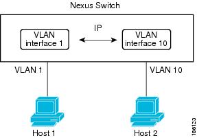
The following figure shows two hosts connected to two VLANs on a device. You can configure VLAN interfaces for each VLAN that allows Host 1 to communicate with Host 2 using IP routing between the VLANs. VLAN 1 communicates at Layer 3 over VLAN interface 1and VLAN 10 communicates at Layer 3 over VLAN interface 10.

Figure 2. Connecting Two VLANs with VLAN Interfaces


Loopback Interfaces

A loopback interface is a virtual interface with a single endpoint that is always up. Any packet that is transmitted over a loopback interface is immediately received by this interface. Loopback interfaces emulate a physical interface.

You can use loopback interfaces for performance analysis, testing, and local communications. Loopback interfaces can act as a termination address for routing protocol sessions. This loopback configuration allows routing protocol sessions to stay up even if some of the outbound interfaces are down.

IP Addressing Scheme with Private VLANs

When you assign a separate VLAN to each customer, an inefficient IP addressing scheme is created as follows:

  • Assigning a block of addresses to a customer VLAN can result in unused IP addresses.

  • If the number of devices in the VLAN increases, the number of assigned addresses might not be large enough to accommodate them.

These problems are reduced by using private VLANs, where all members in the private VLAN share a common address space, which is allocated to the primary VLAN. Hosts are connected to secondary VLANs, and the DHCP server assigns them IP addresses from the block of addresses allocated to the primary VLAN. Subsequent IP addresses can be assigned to customer devices in different secondary VLANs, but in the same primary VLAN. When new devices are added, the DHCP server assigns them the next available address from a large pool of subnet addresses.

Licensing Requirements for Layer 3 Interfaces

After installing a Layer 3 license, the following guidelines and limitations apply to the device:

  • In Service Software Upgrades (ISSUs) are not supported.

  • Temporary Layer 3 feature licenses are not supported. (The Layer 3 Base Services Package license has a grace period of 0.)

  • Management Switch Virtual Interfaces (SVIs) are supported without a Layer 3 Base Services Package license, and ISSU can be performed with Management SVIs configured.

  • All SVIs (whether management keyword is configured or not) are operationally up when no Layer 3 Base Services Package license is installed. After the Layer 3 Base Services Packages feature license is installed, routed SVIs are brought operationally down and then brought back up again. This reload happens because the routed SVIs behave like management SVIs before a Layer 3 Base Services Packages feature license is installed, and the interface state saved in the hardware needs to be cleared followed by programming of the SVI routes in the Forwarding Information Base (FIB).

  • After clearing a Layer 3 license, you must copy the running-configuration to the startup-configuration and reload the device. Then, you can perform a non-disruptive ISSU.

  • After clearing a Layer 3 license, you must copy the running-configuration to the startup-configuration and reload the device. Then, you can perform a non-disruptive ISSU.

  • Although HSRP and VRRP do not need to be removed before clearing a Layer 3 license, we recommend that you clear their configurations as well.

  • Although VRRP and HSRP can be configured without a Layer 3 license, they will not work without a Layer 3 license. If they are configured, non-disruptive ISSU is not supported.

Guidelines and Limitations for Layer 3 Interfaces

Layer 3 interfaces have the following configuration guidelines and limitations:

  • If you change a Layer 3 interface to a Layer 2 interface, Cisco NX-OS shuts down the interface, reenables the interface, and removes all configuration specific to Layer 3.

  • If you change a Layer 2 interface to a Layer 3 interface, Cisco NX-OS shuts down the interface, reenables the interface, and deletes all configuration specific to Layer 2.

  • Configuring a subinterface on a physical interface that is configured to be a member of a port-channel is not supported. One must configure the subinterface under the port-channel interface itself.

  • FHRP is supported only for VPC VLANs, and not supported for non-VPC VLAN with VPC topologies. Refer to Table 1 in Supported Topologies for Routing over Virtual Port Channel on Nexus Platforms.

  • Cisco Nexus 5500 Series switches support only 59 Layer 3 physical interfaces.

Default Settings for Layer 3 Interfaces

The default setting for the Layer 3 Admin state is Shut.

Configuring Layer 3 Interfaces

Configuring a Routed Interface

Procedure

  Command or Action Purpose

Step 1

switch# configure terminal

Enters global configuration mode.

Step 2

switch(config)# interface ethernet slot/port

Enters interface configuration mode.

Note


If this is a QSFP+ GEM or a breakout port, the port syntax is QSFP-module/port .

Step 3

switch(conifg-if)# no switchport

Configures the interface as a Layer 3 interface and deletes any configuration specific to Layer 2 on this interface.

Note


To convert a Layer 3 interface back into a Layer 2 interface, use the switchport command.

Step 4

switch(config-if)# [ip|ipv6]ip-address/length

Configures an IP address for this interface.

Step 5

(Optional) switch(config-if)# medium {broadcast | p2p}

(Optional)

Configures the interface medium as either point to point or broadcast.

Note


The default setting is broadcast, and this setting does not appear in any of the show commands. However, if you do change the setting to p2p , you will see this setting when you enter the show running-config command.

Step 6

(Optional) switch(config-if)# show interfaces

(Optional)

Displays the Layer 3 interface statistics.

Step 7

(Optional) switch(config-if)# copy running-config startup-config

(Optional)

Saves the change persistently through reboots and restarts by copying the running configuration to the startup configuration.

Example

This example shows how to configure an IPv4-routed Layer 3 interface:


switch# configure terminal
switch(config)# interface ethernet 2/1
switch(config-if)# no switchport
switch(config-if)# ip address 192.0.2.1/8
switch(config-if)# copy running-config startup-config

Configuring a Subinterface

Before you begin

  • Configure the parent interface as a routed interface.

  • Create the port-channel interface if you want to create a subinterface on that port channel.

Procedure

  Command or Action Purpose

Step 1

(Optional) switch(config-if)# copy running-config startup-config

(Optional)

Saves the change persistently through reboots and restarts by copying the running configuration to the startup configuration.

Step 2

switch(config)# interface ethernet slot/port.number

Enters interface configuration mode. The range for the slot is from 1 to 255. The range for the port is from 1 to 128.

Note


If this is a QSFP+ GEM or a breakout port, the port syntax is QSFP-module/port .

Step 3

switch(config-if)# [ip | ipv6] address ip-address/length

Configures an IP address for this interface.

Step 4

switch(config-if)# encapsulation dot1Q vlan-id

Configures IEEE 802.1Q VLAN encapsulation on the subinterface. The range for the vlan-id is from 2 to 4093.

Step 5

(Optional) switch(config-if)# show interfaces

(Optional)

Displays the Layer 3 interface statistics.

Step 6

(Optional) switch(config-if)# copy running-config startup-config

(Optional)

Saves the change persistently through reboots and restarts by copying the running configuration to the startup configuration.

Example

This example shows how to create a subinterface:


switch# configure terminal
switch(config)# interface ethernet 2/1
switch(config-if)# ip address 192.0.2.1/8
switch(config-if)# encapsulation dot1Q 33
switch(config-if)# copy running-config startup-config

Configuring the Bandwidth on an Interface

You can configure the bandwidth for a routed interface, port channel, or subinterface.

Procedure

  Command or Action Purpose

Step 1

switch# configure terminal

Enters global configuration mode.

Step 2

switch(config)# interface ethernet slot/port

Enters interface configuration mode. The range for the slot is from 1 to 255. The range for the port is from 1 to 128.

Note


If this is a QSFP+ GEM or a breakout port, the port syntax is QSFP-module/port .

Step 3

switch(conifg-if)# bandwidth [value | inherit [value]]

Configures the bandwidth parameter for a routed interface, port channel, or subinterface, as follows:
  • value—Size of the bandwidth in kilobytes. The range is from 1 to 10000000.

  • inherit —Indicates that all subinterfaces of this interface inherit either the bandwidth value (if a value is specified) or the bandwidth of the parent interface (if a value is not specified).

Step 4

(Optional) switch(config-if)# copy running-config startup-config

(Optional)

Saves the change persistently through reboots and restarts by copying the running configuration to the startup configuration.

Example

This example shows how to configure Ethernet interface 2/1 with a bandwidth value of 80000:


switch# configure terminal
switch(config)# interface ethernet 2/1
switch(config-if)# bandwidth 80000
switch(config-if)# copy running-config startup-config

Configuring a VLAN Interface

Procedure

  Command or Action Purpose

Step 1

switch# configure terminal

Enters global configuration mode.

Step 2

switch(config)# feature interface-vlan

Enables VLAN interface mode.

Step 3

switch(config)# interface vlan number

Creates a VLAN interface. The number range is from 1 to 4094.

Step 4

switch(config-if)# [ip | ipv6 ] address ip-address/length

Configures an IP address for this interface.

Step 5

switch(config-if)# no shutdown

Brings the interface up administratively.

Step 6

(Optional) switch(config-if)# show interface vlan number

(Optional)

Displays the VLAN interface statistics. The number range is from 1 to 4094.

Step 7

(Optional) switch(config-if)# copy running-config startup-config

(Optional)

Saves the change persistently through reboots and restarts by copying the running configuration to the startup configuration.

Example

This example shows how to create a VLAN interface:


switch# configure terminal
switch(config)# feature interface-vlan
switch(config)# interface vlan 10
switch(config-if)# ip address 192.0.2.1/8
switch(config-if)# copy running-config startup-config

Mapping Secondary VLANs to the Layer 3 VLAN Interface of a Primary VLAN

To map secondary VLANs to the Layer 3 VLAN interface of a primary VLAN to allow Layer 3 switching of private VLAN ingress traffic, perform this task:

Procedure

  Command or Action Purpose

Step 1

Router(config)# interface-vlan primary_vlan_ID

Enters interface configuration mode for the primary VLAN.

Note


Isolated and community VLANs are both called secondary VLANs.

Step 2

Router(config-if)# private-vlan mapping {secondary_vlan_list | add secondary_vlan_list | remove secondary_vlan_list}

Maps the secondary VLANs to the Layer 3 VLAN interface of a primary VLAN to allow Layer 3 switching of private VLAN ingress traffic.

When you map secondary VLANs to the Layer 3 VLAN interface of a primary VLAN, note the following information:

  • The private-vlan mapping interface configuration command only affects private VLAN ingress traffic that is Layer 3-switched.

  • The secondary_vlan_list parameter cannot contain spaces. It can contain multiple comma-separated items. Each item can be a single private VLAN ID or a hyphenated range of private VLAN IDs.

  • Enter a secondary_vlan_list parameter or use the add keyword with a secondary_vlan_list parameter to map the secondary VLANs to the primary VLAN.

  • Use the remove keyword with a secondary_vlan_list parameter to clear the mapping between secondary VLANs and the primary VLAN.

Step 3

Router(config-if)# no private-vlan mapping

Clears the mapping between the secondary VLANs and the primary VLAN.

Step 4

Router(config-if)# end

Exits configuration mode.

Step 5

Router show interface private-vlan mapping

Verifies the configuration.

Example

This example shows how to permit routing of secondary VLAN ingress traffic from private VLANs 303 through 307, 309, and 440 and verify the configuration:

Router# configure terminal 
 Router(config)# interface vlan 202 
 Router(config-if)# private-vlan mapping add 303-307,309,440 
 Router(config-if)# end 
 Router# show interfaces private-vlan mapping 
 Interface Secondary VLAN Type
 --------- -------------- -----------------
 vlan202   303            community
 vlan202   304            community
 vlan202   305            community
 vlan202   306            community
 vlan202   307            community
 vlan202   309            community
 vlan202   440            isolated
 Router#

Configuring a Loopback Interface

Before you begin

Ensure that the IP address of the loopback interface is unique across all routers on the network.

    Procedure

      Command or Action Purpose

    Step 1

    switch# configure terminal

    Enters global configuration mode.

    Step 2

    switch(config)# interface loopback instance

    Creates a loopback interface. The instance range is from 0 to 1023.

    Step 3

    switch(config-if)# [ip | ipv6 ] address ip-address/length

    Configures an IP address for this interface.

    Step 4

    (Optional) switch(config-if)# show interface loopback instance

    (Optional)

    Displays the loopback interface statistics. The instance range is from 0 to 1023.

    Step 5

    (Optional) switch(config-if)# copy running-config startup-config

    (Optional)

    Saves the change persistently through reboots and restarts by copying the running configuration to the startup configuration.

    Example

    This example shows how to create a loopback interface:

    
    switch# configure terminal
    switch(config)# interface loopback 0
    switch(config-if)# ip address 192.0.2.100/8
    switch(config-if)# copy running-config startup-config
    

    Assigning an Interface to a VRF

    Before you begin

    Assign the IP address for a tunnel interface after you have configured the interface for a VRF.

      Procedure

        Command or Action Purpose

      Step 1

      switch# configure terminal

      Enters global configuration mode.

      Step 2

      switch(config)# interface interface-typenumber

      Enters interface configuration mode.

      Step 3

      switch(conifg-if)#vrf member vrf-name

      Adds this interface to a VRF.

      Step 4

      switch(config-if)# [ip | ipv6]ip-address/length

      Configures an IP address for this interface. You must do this step after you assign this interface to a VRF.

      Step 5

      (Optional) switch(config-if)# show vrf [vrf-name] interface interface-type number

      (Optional)

      Displays VRF information.

      Step 6

      (Optional) switch(config-if)# show interfaces

      (Optional)

      Displays the Layer 3 interface statistics.

      Step 7

      (Optional) switch(config-if)# copy running-config startup-config

      (Optional)

      Saves the change persistently through reboots and restarts by copying the running configuration to the startup configuration.

      Example

      This example shows how to add a Layer 3 interface to the VRF:

      switch# configure terminal 
      switch(config)# interface loopback 0 
      switch(config-if)# vrf member RemoteOfficeVRF 
      switch(config-if)# ip address 209.0.2.1/16 
      switch(config-if)# copy running-config startup-config 
      

      Verifying the Layer 3 Interfaces Configuration

      Use one of the following commands to verify the configuration:

      Command

      Purpose

      show interface ethernet slot/port

      Displays the Layer 3 interface configuration, status, and counters (including the 5-minute exponentially decayed moving average of inbound and outbound packet and byte rates).

      Note


      If this is a QSFP+ GEM or a breakout port, the port syntax is QSFP-module/port .

      show interface ethernet slot/port brief

      Displays the Layer 3 interface operational status.

      Note


      If this is a QSFP+ GEM or a breakout port, the port syntax is QSFP-module/port .

      show interface ethernet slot/port capabilities

      Displays the Layer 3 interface capabilities, including port type, speed, and duplex.

      Note


      If this is a QSFP+ GEM or a breakout port, the port syntax is QSFP-module/port .

      show interface ethernet slot/port description

      Displays the Layer 3 interface description.

      Note


      If this is a QSFP+ GEM or a breakout port, the port syntax is QSFP-module/port .

      show interface ethernet slot/port status

      Displays the Layer 3 interface administrative status, port mode, speed, and duplex.

      Note


      If this is a QSFP+ GEM or a breakout port, the port syntax is QSFP-module/port .

      show interface ethernet slot/port.number

      Displays the subinterface configuration, status, and counters (including the f-minute exponentially decayed moving average of inbound and outbound packet and byte rates).

      Note


      If this is a QSFP+ GEM or a breakout port, the port syntax is QSFP-module/port .

      show interface port-channel channel-id.number

      Displays the port-channel subinterface configuration, status, and counters (including the 5-minute exponentially decayed moving average of inbound and outbound packet and byte rates).

      show interface loopback number

      Displays the loopback interface configuration, status, and counters.

      show interface loopback number brief

      Displays the loopback interface operational status.

      show interface loopback number description

      Displays the loopback interface description.

      show interface loopback number status

      Displays the loopback interface administrative status and protocol status.

      show interface vlan number

      Displays the VLAN interface configuration, status, and counters.

      show interface vlan number brief

      Displays the VLAN interface operational status.

      show interface vlan number description

      Displays the VLAN interface description.

      show interface vlan number private-vlan mapping

      Displays the VLAN interface private VLAN information.

      show interface vlan number status

      Displays the VLAN interface administrative status and protocol status.

      Monitoring Layer 3 Interfaces

      Use one of the following commands to display statistics about the feature:

      Command

      Purpose

      show interface ethernet slot/port counters

      Displays the Layer 3 interface statistics (unicast, multicast, and broadcast).

      Note


      If this is a QSFP+ GEM or a breakout port, the port syntax is QSFP-module/port .

      show interface ethernet slot/port counters brief

      Displays the Layer 3 interface input and output counters.

      Note


      If this is a QSFP+ GEM or a breakout port, the port syntax is QSFP-module/port .

      show interface ethernet slot/port counters detailed [all]

      Displays the Layer 3 interface statistics. You can optionally include all 32-bit and 64-bit packet and byte counters (including errors).

      Note


      If this is a QSFP+ GEM or a breakout port, the port syntax is QSFP-module/port .

      show interface ethernet slot/port counters error

      Displays the Layer 3 interface input and output errors.

      Note


      If this is a QSFP+ GEM or a breakout port, the port syntax is QSFP-module/port .

      show interface ethernet slot/port counters snmp

      Displays the Layer 3 interface counters reported by SNMP MIBs. You cannot clear these counters.

      Note


      If this is a QSFP+ GEM or a breakout port, the port syntax is QSFP-module/port .

      show interface ethernet slot/port.number counters

      Displays the subinterface statistics (unicast, multicast, and broadcast).

      Note


      If this is a QSFP+ GEM or a breakout port, the port syntax is QSFP-module/port .

      show interface port-channel channel-id.number counters

      Displays the port-channel subinterface statistics (unicast, multicast, and broadcast).

      show interface loopback number counters

      Displays the loopback interface input and output counters (unicast, multicast, and broadcast).

      show interface loopback number counters detailed [all]

      Displays the loopback interface statistics. You can optionally include all 32-bit and 64-bit packet and byte counters (including errors).

      show interface loopback number counters errors

      Displays the loopback interface input and output errors.

      show interface vlan number counters

      Displays the VLAN interface input and output counters (unicast, multicast, and broadcast).

      show interface vlan number counters detailed [all]

      Displays the VLAN interface statistics. You can optionally include all Layer 3 packet and byte counters (unicast and multicast).

      show interface vlan counters snmp

      Displays the VLAN interface counters reported by SNMP MIBs. You cannot clear these counters.

      Configuration Examples for Layer 3 Interfaces

      This example shows how to configure Ethernet subinterfaces:
      
      switch# configuration terminal
      switch(config)# interface ethernet 2/1.10
      switch(config-if)# description Layer 3 for VLAN 10
      switch(config-if)# encapsulation dot1q 10
      switch(config-if)# ip address 192.0.2.1/8
      switch(config-if)# copy running-config startup-config
      This example shows how to configure a VLAN interface:
      
      switch# configuration terminal
      switch(config)# interface vlan 100
      switch(config-if)# no switchport
      
      switch(config-if)# ipv6 address 33:0DB::2/8
      switch(config-if)# copy running-config startup-config
      This example shows how to configure a loopback interface:
      
      switch# configuration terminal
      switch(config)# interface loopback 3
      switch(config-if)# no switchport
      switch(config-if)# ip address 192.0.2.2/32
      switch(config-if)# copy running-config startup-config

      Related Documents for Layer 3 Interfaces

      Related Topics Document Title

      Command syntax

      For details about command syntax, see the command reference for your device.

      IP

      “Configuring IP” chapter in the Unicast Routing Configuration Guide for your device.

      VLAN

      “Configuring VLANs” chapter in the Layer 2 Switching Configuration Guide for your device.

      Standards for Layer 3 Interfaces

      No new or modified standards are supported by this feature, and support for existing standards has not been modified by this feature.