Configuring Cisco TrustSec

This chapter describes how to configure Cisco TrustSec on Cisco NX-OS devices.

This chapter includes the following sections:

Information About Cisco TrustSec

This section provides information about Cisco TrustSec.

Cisco TrustSec Architecture

The Cisco TrustSec security architecture builds secure networks by establishing clouds of trusted network devices. Cisco TrustSec also uses the device information acquired during authentication for classifying, or coloring, the packets as they enter the network. This packet classification is maintained by tagging packets on ingress to the Cisco TrustSec network so that they can be properly identified for the purpose of applying security and other policy criteria along the data path. The tag, also called the security group tag (SGT), allows the network to enforce the access control policy by enabling the endpoint device to act upon the SGT to filter traffic.


Note

Ingress refers to entering the first Cisco TrustSec-capable device encountered by a packet on its path to the destination and egress refers to leaving the last Cisco TrustSec-capable device on the path.


Figure 1. Cisco TrustSec Network Cloud Example. This figure shows an example of a Cisco TrustSec cloud. In this example, several networking devices and an endpoint device are inside the Cisco TrustSec cloud. One endpoint device and one networking device are outside the cloud because they are not Cisco TrustSec-capable devices.

The Cisco TrustSec architecture consists of the following major components:

Authentication
Verifies the identity of each device before allowing them to join the Cisco TrustSec network.
Authorization
Decides the level of access to the Cisco TrustSec network resources for a device based on the authenticated identity of the device.
Access control
Applies access policies on a per-packet basis using the source tags on each packet.

A Cisco TrustSec network has the following entities:

Authenticators (AT)
Devices that are already part of a Cisco TrustSec network.
Authorization server (AS)
Servers that may provide authentication information, authorization information, or both.

When the link first comes up, authorization occurs in which each side of the link obtains policies, such as SGT and ACLs, that apply to the link.

Authentication

Cisco TrustSec authenticates a device before allowing it to join the network.

Device Identities

Cisco TrustSec does not use IP addresses or MAC addresses as device identities. Instead, assign a name (device ID) to each Cisco TrustSec-capable Cisco NX-OS device to identify it uniquely in the Cisco TrustSec network. This device ID is used for the following:

  • Looking up authorization policy

  • Looking up passwords in the databases during authentication

Device Credentials

Cisco TrustSec supports password-based credentials. The authentication servers may use self-signed certificates instead. Cisco TrustSec authenticates the supplicants through passwords and uses MSCHAPv2 to provide mutual authentication even if the authentication server certificate is not verifiable.

The authentication server uses a temporarily configured password to authenticate the supplicant when the supplicant first joins the Cisco TrustSec network. When the supplicant first joins the Cisco TrustSec network, the authentication server authenticates the supplicant using a manufacturing certificate and then generates a strong password and pushes it to the supplicant with the PAC. The authentication server also keeps the new password in its database.

User Credentials

Cisco TrustSec does not require a specific type of user credentials for endpoint devices. You can choose any type of authentication method for the user (for example, MSCHAPv2, LEAP, generic token card (GTC), or OTP) and use the corresponding credentials.

SGACLs and SGTs

In security group access lists (SGACLs), you can control the operations that users can perform based on assigned security groups. The grouping of permissions into a role simplifies the management of the security policy. As you add users to a Cisco NX-OS device, you simply assign one or more security groups and they immediately receive the appropriate permissions. You can modify security groups to introduce new privileges or restrict current permissions.

Cisco TrustSec assigns a unique 16-bit tag, called the security group tag (SGT), to a security group. The number of SGTs in a Cisco NX-OS device is limited to the number of authenticated network entities. The SGT is a single label that indicates the privileges of the source within the entire enterprise. Its scope is global within a Cisco TrustSec network.

The management server derives the SGTs based on the security policy configuration. You do not have to configure them manually.

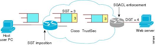
Once authenticated, Cisco TrustSec tags any packet that originates from a device with the SGT that represents the security group to which the device is assigned. The packet carries this SGT throughout the network within the Cisco TrustSec header. Because this tag represents the group of the source, the tag is referred to as the source SGT. At the egress edge of the network, Cisco TrustSec determines the group that is assigned to the packet destination device and applies the access control policy.

Cisco TrustSec defines access control policies between the security groups. By assigning devices within the network to security groups and applying access control between and within the security groups, Cisco TrustSec essentially achieves access control within the network.

Figure 2. SGACL Policy Example. This figure shows an example of an SGACL policy.
Figure 3. SGT and SGACL in Cisco TrustSec Network. This figure shows how the SGT assignment and the SGACL enforcement operate in a Cisco TrustSec network.

The Cisco NX-OS device defines the Cisco TrustSec access control policy for a group of devices as opposed to IP addresses in traditional ACLs. With such a decoupling, the network devices are free to move throughout the network and change IP addresses. Entire network topologies can change. As long as the roles and the permissions remain the same, changes to the network do not change the security policy. This feature greatly reduces the size of ACLs and simplifies their maintenance.

In traditional IP networks, the number of access control entries (ACEs) configured is determined as follows:

Number of ACEs = (number of sources specified) X (number of destinations specified) X (number of permissions specified)

Cisco TrustSec uses the following formula:

Number of ACEs = number of permissions specified

For information about SGACL policy enforcement with SGT caching, see SGACL Policy Enforcement With Cisco TrustSec SGT Caching.

Determining the Source Security Group

A network device at the ingress of the Cisco TrustSec network cloud needs to determine the SGT of the packet entering the Cisco TrustSec network cloud so that it can tag the packet with that SGT when it forwards it into the Cisco TrustSec network cloud. The egress network device needs to determine the SGT of the packet so that it can apply the SGACLs.

The network device can determine the SGT for a packet using one of the following methods:

  • Obtain the source SGT during policy acquisition—After the Cisco TrustSec authentication phase, a network device acquires a policy from an authentication server. The authentication server indicates whether the peer device is trusted or not. If a peer device is not trusted, the authentication server can also provide an SGT to apply to all packets coming from the peer device.

  • Obtain the source SGT field from the Cisco TrustSec header—If a packet comes from a trusted peer device, the Cisco TrustSec header carries the correct SGT field if the network device is not the first network device in the Cisco TrustSec network cloud for the packet.

Determining the Destination Security Group

The egress network device in a Cisco TrustSec network cloud determines the destination group for applying the SGACL. In some cases, ingress devices or other nonegress devices might have destination group information available. In those cases, SGACLs might be applied in these devices rather than in egress devices.

Cisco TrustSec determines the destination group for the packet based on the destination IP address.

Do not configure the destination SGT to enforce Cisco TrustSec on egress broadcast, multicast, and unknown unicast traffic on Fabric Extender (FEX) or vEthernet ports. Instead, set the DST to zero (unknown). The following is an example of the correct configuration:

cts role-based access-list acl-on-fex-egress
     deny udp
					deny ip
cts role-based sgt 9 dst 0 access-list acl-on-fex-egress

SXP for SGT Propagation Across Legacy Access Networks

The Cisco NX-OS device hardware in the access layer supports Cisco TrustSec. Without the Cisco TrustSec hardware, the Cisco TrustSec software cannot tag the packets with SGTs. You can use SXP to propagate the SGTs across network devices that do not have hardware support for Cisco TrustSec.

SXP operates between access layer devices and distribution layer devices. The access layer devices use SXP to pass the IP addresses of the Cisco TrustSec-authenticated devices with their SGTs to the distribution switches. Distribution devices with both Cisco TrustSec-enabled software and hardware can use this information to tag packets appropriately and enforce SGACL policies.

Figure 4. Using SXP to Propagate SGT Information. This figure shows how to use SXP to propagate SGT information in a legacy network.

Tagging packets with SGTs requires hardware support. You might have devices in your network that cannot tag packets with SGTs. To allow these devices to send IP address-to-SGT mappings to a device that has Cisco TrustSec-capable hardware, you must manually set up the SXP connections. Manually setting up an SXP connection requires the following:

  • If you require SXP data integrity and authentication, you must configure the same SXP password on both of the peer devices. You can configure the SXP password either explicitly for each peer connection or globally for the device. The SXP password is not required.

  • You must configure each peer on the SXP connection as either an SXP speaker or an SXP listener. The speaker device distributes the SXP information to the listener device.


    Note

    This Cisco Nexus device does not have the functionality to be an SXP listener. It can only be an SXP speaker.


  • You can specify a source IP address to use for each peer relationship or you can configure a default source IP address for peer connections where you have not configured a specific source IP address.

Environment Data Download

The Cisco TrustSec environment data is a collection of information or policies that assists a device to function as a Cisco TrustSec node. The device acquires the environment data from the authentication server when the device first joins a Cisco TrustSec network cloud, although you might also manually configure some of the data on a device. For example, you must configure the seed Cisco TrustSec device with the authentication server information, which can later be augmented by the server list that the device acquires from the authentication server.


Note

If you have manually configured the Cisco TrustSec device ID, but not using the AAA server for a Cisco TrustSec deployment, you should remove the Cisco TrustSec device ID by using the no cts device-id command. Otherwise, the following false syslog error is generated:

ENVIRONMENT_DATA_DOWNLOAD_FAILURE:  Environment data download failed from AAA

The no cts device-id command is supported from Cisco NX-OS Release 7.2. If you are using Cisco NX-OS Release 6.2.6 or a later release, you can disable only by disabling Cisco TrustSec and reapplying Cisco TrustSec configurations without the cts device-id configuration.


The device must refresh the Cisco TrustSec environment data before it expires. The device can also cache the data and reuse it after a reboot if the data has not expired.

The device uses RADIUS to acquire the following environment data from the authentication server:

Server lists
List of servers that the client can use for future RADIUS requests (for both authentication and authorization)
Device SGT
Security group to which the device itself belongs
Expiry timeout
Interval that controls how often the Cisco TrustSec device should refresh its environment data

Licensing Requirements for Cisco TrustSec

The following table shows the licensing requirements for this feature:

Table 1. Licensing Requirements for Cisco TrustSec

Product

License Requirement

Cisco NX-OS

Cisco TrustSec requires no license. Any feature not included in a license package is bundled with the Cisco NX-OS system images and is provided at no extra charge to you. For a complete explanation of the Cisco NX-OS licensing scheme, see the License and Copyright Information for Cisco NX-OS Software.

Prerequisites for Cisco TrustSec

Cisco TrustSec has the following prerequisites:

  • You must enable the 802.1X feature before you enable the Cisco TrustSec feature. Although none of the 802.1X interface level features are available, 802.1X is required for the device to authenticate with RADIUS.

Guidelines and Limitations for Cisco TrustSec

Cisco TrustSec has the following guidelines and limitations:

  • Cisco TrustSec uses RADIUS for authentication.

  • AAA authentication and authorization for Cisco TrustSec is only supported by the Cisco Identity Services Engine (ISE) .

  • Cisco TrustSec supports IPv4 addressing only.

  • SXP cannot use the management (mgmt 0) interface.

  • You cannot enable Cisco TrustSec on interfaces in half-duplex mode.

  • Clearing policies does not take affect immediately; it requires a flap to occur. In addition, the way policies are cleared depends on whether the SGT is static or dynamic. For a static SGT, the SGT is reset to 0 after the flap occurs. For dynamic SGT, the SGT is downloaded again from the RADIUS server after the flap occurs.

  • Cisco TrustSec supports management switch virtual interfaces (SVIs), not routed SVIs.

  • The 802.1X feature must be enabled before you enable the Cisco TrustSec feature. The 802.1X feature is only used for the device to authenticate with RADIUS.

  • RBACL is only implemented on bridged Ethernet traffic and cannot be enabled on a routing VLAN or routing interface.

  • The determination of whether a peer is trusted or not and its capability to propagate SGTs on egress are made at the physical interface level.

  • Cisco TrustSec interface configurations on port channel members must be exactly the same. If a port channel member is inconsistent with the other port channel members, it will be error disabled.

  • In a vPC domain, use the configuration synchronization mode (config-sync) to create switch profiles to ensure that the Cisco TrustSec configuration is synchronized between peers. If you configure the same vPC differently on two peer switches, traffic is treated differently.

  • The maximum number of RBACL TCAM entries is 128, with 4 entries used by default, and the remaining 124 entries user-configurable.

  • Cisco TrustSec is not supported on Layer 3 interfaces or Virtual Routing and Forwarding (VRF) interfaces.

  • The cts-manual, cts trusted mode, and no-propagate sgt configurations must be consistent among all FEX ports or vEthernet ports on the same fabric port. If these configurations are inconsistent, the interfaces are err-disabled.

  • The cts-manual, sgt value, cts trusted mode, and no-propagate sgt configurations must be consistent among all port channel members on the same port channel. If these configurations are inconsistent, the interfaces are err-disabled.

Default Settings for Cisco TrustSec Parameters

This table lists the default settings for Cisco TrustSec parameters.

Table 2. Default Cisco TrustSec Parameters Settings

Parameter

Default

Cisco TrustSec

Disabled

Cisco TrustSec Batched Programming

Disabled

SXP

Disabled

SXP default password

None

SXP reconcile period

120 seconds (2 minutes)

SXP retry period

60 seconds (1 minute)

RBACL logging

Disabled

RBACL statistics

Disabled

Configuring Cisco TrustSec

This section provides information about the configuration tasks for Cisco TrustSec.

Enabling the Cisco TrustSec SGT Feature

You must enable both the 802.1X feature and the Cisco TrustSec feature on the Cisco NX-OS device before you can configure Cisco TrustSec. However, none of the 802.1X interface level features are available. The 802.1X feature is only used for the device to authenticate with RADIUS.

Procedure

  Command or Action Purpose
Step 1

configure terminal

Example:

switch# configure terminal
switch(config)#

Enters global configuration mode.

Step 2

feature dot1x

Example:

switch(config)# feature dot1x

Enables the 802.1X feature.

Step 3

feature cts

Example:

switch(config)# feature cts

Enables the Cisco TrustSec feature.

Step 4

exit

Example:

switch(config)# exit
switch#

Exits global configuration mode.

Step 5

(Optional) show cts

Example:

switch# show cts
(Optional)

Displays the Cisco TrustSec configuration.

Step 6

(Optional) show feature

Example:

switch# show feature
(Optional)

Displays the enabled status for features.

Step 7

(Optional) copy running-config startup-config

Example:

switch# copy running-config startup-config
(Optional)

Copies the running configuration to the startup configuration.

Configuring Cisco TrustSec Device Credentials

You must configure unique Cisco TrustSec credentials on each Cisco TrustSec-enabled Cisco NX-OS device in your network. Cisco TrustSec uses the password in the credentials for device authentication.


Note

You must also configure the Cisco TrustSec credentials for the Cisco NX-OS device on the Cisco ISE. See the documentation at:

http://www.cisco.com/c/en/us/support/security/secure-access-control-system/products-installation-and-configuration-guides-list.html

Before you begin

Ensure that you have enabled Cisco TrustSec.

Procedure

  Command or Action Purpose
Step 1

configure terminal

Example:

switch# configure terminal
switch(config)#

Enters global configuration mode.

Step 2

cts device-id name password password

Example:

switch(config)# cts device-id MyDevice1 password CiscO321

Configures a unique device ID and password. The name argument has a maximum length of 32 characters and is case sensitive.

Note 

To remove the configuration of device ID and the password, use the no form of the command.

Step 3

exit

Example:

switch(config)# exit
switch#

Exits global configuration mode.

Step 4

(Optional) show cts

Example:

switch# show cts
(Optional)

Displays the Cisco TrustSec configuration.

Step 5

(Optional) show cts environment

Example:

switch# show cts environment
(Optional)

Displays the Cisco TrustSec environment data.

Step 6

(Optional) copy running-config startup-config

Example:

switch# copy running-config startup-config
(Optional)

Copies the running configuration to the startup configuration.

Configuring AAA for Cisco TrustSec

You can use Cisco ISE for Cisco TrustSec authentication. You must configure RADIUS server groups and specify the default AAA authentication and authorization methods on one of the Cisco TrustSec-enabled Cisco NX-OS devices in your network cloud.

Configuring AAA on a Cisco NX-OS Device in a Cisco TrustSec Network

This section describes how to configure AAA on the Cisco NX-OS device in your Cisco TrustSec network cloud.

Before you begin
  • Obtain the IPv4 address or hostname for the Cisco ISE.

  • Ensure that you enabled Cisco TrustSec.

Procedure
  Command or Action Purpose
Step 1

configure terminal

Example:
switch# configure terminal
switch(config)#

Enters global configuration mode.

Step 2

radius-server host {ipv4-address | ipv6-address | hostname} key [0 | 7 ] key pac

Example:
switch(config)# radius-server host 10.10.1.1 key L1a0K2s9 pac

Configures a RADIUS server host with a key and PAC. The hostname argument is alphanumeric, case sensitive, and has a maximum of 256 characters. The key argument is alphanumeric, case sensitive, and has a maximum length of 63 characters. The 0 option indicates that the key is in clear text. The 7 option indicates that the key is encrypted. The default is clear text.

Step 3

(Optional) show radius-server

Example:
switch# show radius-server
(Optional)

Displays the RADIUS server configuration.

Step 4

aaa group server radius group-name

Example:
switch(config)# aaa group server radius Rad1
switch(config-radius)#

Specifies the RADIUS server group and enters RADIUS server group configuration mode.

Step 5

server {ipv4-address | ipv6-address | hostname}

Example:
switch(config-radius)# server 10.10.1.1

Specifies the RADIUS server host address.

Step 6

use-vrf vrf-name

Example:
switch(config-radius)# use-vrf management

Specifies the management VRF instance for the AAA server group.

Note 

If you use the management VRF instance, no further configuration is necessary for the devices in the network cloud. If you use a different VRF instance, you must configure the devices with that VRF instance.

Step 7

exit

Example:
switch(config-radius)# exit
switch(config)#

Exits RADIUS server group configuration mode.

Step 8

aaa authentication cts default group group-name

Example:
switch(config)# aaa authentication cts default group Rad1

Specifies the RADIUS server groups to use for Cisco TrustSec authentication.

Step 9

aaa authorization cts default group group-name

Example:
switch(config)# aaa authentication cts default group Rad1

Specifies the RADIUS server groups to use for Cisco TrustSec authorization.

Step 10

exit

Example:
switch(config)# exit
switch#

Exits global configuration mode.

Step 11

(Optional) show radius-server groups [group-name]

Example:
switch# show radius-server group rad1
(Optional)

Displays the RADIUS server group configuration.

Step 12

(Optional) show aaa authentication

Example:
switch# show aaa authentication
(Optional)

Displays the AAA authentication configuration.

Step 13

(Optional) show aaa authorization

Example:
switch# show aaa authorization
(Optional)

Displays the AAA authorization configuration.

Step 14

(Optional) show cts pacs

Example:
switch# show cts pacs
(Optional)

Displays the Cisco TrustSec PAC information.

Step 15

(Optional) copy running-config startup-config

Example:
switch# copy running-config startup-config
(Optional)

Copies the running configuration to the startup configuration.

Configuring Cisco TrustSec Authentication in Manual Mode

You can manually configure Cisco TrustSec on an interface if your Cisco NX-OS device does not have access to a Cisco ISE. You must manually configure the interfaces on both ends of the connection.


Caution

For the Cisco TrustSec manual mode configuration to take effect, you must enable and disable the interface, which disrupts traffic on the interface.


Before you begin

Ensure that you enabled Cisco TrustSec.

Procedure

  Command or Action Purpose
Step 1

configure terminal

Example:

switch# configure terminal
switch(config)#

Enters global configuration mode.

Step 2

interface interface slot/port

Example:

switch(config)# interface ethernet 2/2
switch(config-if)#

Specifies an interface and enters interface configuration mode.

Step 3

cts manual

Example:

switch(config-if)# cts manual
switch(config-if-cts-manual)#

Enters Cisco TrustSec manual configuration mode.

Note 

You cannot enable Cisco TrustSec on interfaces in half-duplex mode.

Step 4

(Optional) policy dynamic identity peer-name

Example:

switch(config-if-cts-manual)# policy dynamic identity MyDevice2
(Optional)

Configures a dynamic authorization policy download. The peer-name argument is the Cisco TrustSec device ID for the peer device. The peer name is case sensitive.

Note 

Ensure that you have configured the Cisco TrustSec credentials and AAA for Cisco TrustSec.

Note 

The policy dynamic and policy static commands are mutually exclusive. Only one can be applied at a time. To change from one to the other, you must use the no form of the command to remove the configuration before configuring the other command.

Step 5

(Optional) policy static sgt tag [trusted ]

Example:

switch(config-if-cts-manual)# policy static sgt 0x2 
(Optional)

Configures a static authorization policy. The tag argument is a hexadecimal value in the format 0x hhhh . The range is from 0x2 to 0xffef. The trusted keyword indicates that traffic coming on the interface with this SGT should not have its tag overridden.

Note 

The policy dynamic and policy static commands are mutually exclusive. Only one can be applied at a time. To change from one to the other, you must use the no form of the command to remove the configuration before configuring the other command.

Step 6

exit

Example:

switch(config-if-cts-manual)# exit
switch(config-if)#

Exits Cisco TrustSec manual configuration mode.

Step 7

shutdown

Example:

switch(config-if)# shutdown

Disables the interface.

Step 8

no shutdown

Example:

switch(config-if)# no shutdown

Enables the interface and enables Cisco TrustSec authentication on the interface.

Step 9

exit

Example:

switch(config-if)# exit
switch(config)#

Exits interface configuration mode.

Step 10

(Optional) show cts interface {all | ethernet slot/port}

Example:

switch# show cts interface all
(Optional)

Displays the Cisco TrustSec configuration for the interfaces.

Step 11

(Optional) copy running-config startup-config

Example:

switch# copy running-config startup-config
(Optional)

Copies the running configuration to the startup configuration.

Configuring SGACL Policies

This section provides information about the configuration tasks for SGACL policies.

SGACL Policy Configuration Process

Follow these steps to configure Cisco TrustSec SGACL policies:

Procedure

Step 1

For Layer 2 interfaces, enable SGACL policy enforcement for the VLANs with Cisco TrustSec-enabled interfaces.

Step 2

If you are not using AAA on a Cisco ISE to download the SGACL policy configuration, manually configure the SGACL mapping and policies.


Enabling SGACL Policy Enforcement on VLANs

If you use SGACLs, you must enable SGACL policy enforcement in the VLANs that have Cisco TrustSec-enabled Layer 2 interfaces.


Note

This operation cannot be performed on FCoE VLANs.


Before you begin
  • Ensure that you enabled Cisco TrustSec.

  • Ensure that you enabled SGACL batch programming.

Procedure
  Command or Action Purpose
Step 1

configure terminal

Example:
switch# configure terminal
switch(config)#

Enters global configuration mode.

Step 2

vlan vlan-id

Example:
switch(config)# vlan 10
switch(config-vlan)#

Specifies a VLAN and enters VLAN configuration mode.

Step 3

cts role-based enforcement

Example:
switch(config-vlan)# cts role-based enforcement

Enables Cisco TrustSec SGACL policy enforcement on the VLAN.

Note 

If you enable the cts role-based enforcement on a VLAN and no other configuration on ports, the traffic traversing through these ports are subject to (0,0) SGACL. You can either configure this SGACL statically or download it from Cisco ISE.

Step 4

exit

Example:
switch(config-vlan)# exit
switch(config)#

Saves the VLAN configuration and exits VLAN configuration mode.

Step 5

(Optional) show cts role-based enable

Example:
switch(config)# show cts role-based enable
(Optional)

Displays the Cisco TrustSec SGACL enforcement configuration.

Step 6

(Optional) copy running-config startup-config

Example:
switch(config)# copy running-config startup-config
(Optional)

Copies the running configuration to the startup configuration.

Manually Configuring Cisco TrustSec SGTs

You can manually configure unique Cisco TrustSec security group tags (SGTs) for the packets originating from this device.

Before you begin

Ensure that you have enabled Cisco TrustSec.

Procedure
  Command or Action Purpose
Step 1

configure terminal

Example:
switch# configure terminal
switch(config)#

Enters global configuration mode.

Step 2

cts sgt tag

Example:
switch(config)# cts sgt 0x00a2

Configures the SGT for packets sent from the device. The tag argument is a hexadecimal value in the format 0x hhhh . The range is from 0x2 to 0xffef.

Step 3

exit

Example:
switch(config)# exit
switch#

Exits global configuration mode.

Step 4

(Optional) show cts environment-data

Example:
switch# show cts environment-data
(Optional)

Displays the Cisco TrustSec environment data information.

Step 5

(Optional) copy running-config startup-config

Example:
switch# copy running-config startup-config
(Optional)

Copies the running configuration to the startup configuration.

Manually Configuring IPv4-Address-to-SGACL SGT Mapping for a VLAN

You can manually configure an IPv4 address to SGACL SGT mapping on a VLAN so that the policies for that SGT are downloaded from the ISE server, or if you are using SXP mode, the SGT mapping is relayed to the listener.

Before you begin
  • Ensure that you enabled Cisco TrustSec.

  • Ensure that you enabled SGACL policy enforcement on the VLAN.

Procedure
  Command or Action Purpose
Step 1

configure terminal

Example:
switch# configure terminal
switch(config)#

Enters global configuration mode.

Step 2

vlan vlan-id

Example:
switch(config)# vlan 10
switch(config-vlan)#

Specifies a VLAN and enters VLAN configuration mode.

Step 3

cts role-based sgt-map ipv4-address tag

Example:
switch(config-vlan)# cts role-based sgt-map 10.10.1.1 100

Configures SGT mapping for the SGACL policies for the VLAN.

Step 4

exit

Example:
switch(config-vlan)# exit
switch(config)#

Saves the VLAN configuration and exits VLAN configuration mode.

Step 5

(Optional) show cts role-based sgt-map

Example:
switch(config)# show cts role-based sgt-map
(Optional)

Displays the Cisco TrustSec SGACL SGT mapping configuration.

Step 6

(Optional) copy running-config startup-config

Example:
switch(config)# copy running-config startup-config
(Optional)

Copies the running configuration to the startup configuration.

Manually Configuring IPv4-Address-to-SGACL SGT Mapping for a VRF Instance

You can manually configure IPv4-address-to-SGACL SGT mapping on a VRF instance if a Cisco ISE is not available to download the SGACL policy configuration. You can use this feature if you do not have Cisco ISE available on your Cisco NX-OS device. The IPv4-SGT mapping for VRF is useful for the SXP speaker.


Note

The cts role based enforcement command is not supported on VRF.


Before you begin
  • Ensure that you enabled Cisco TrustSec.

  • Ensure that the Layer-3 module is enabled.

Procedure
  Command or Action Purpose
Step 1

configure terminal

Example:
switch# configure terminal
switch(config)#

Enters global configuration mode.

Step 2

vrf context vrf-name

Example:
switch(config)# vrf context accounting
switch(config-vrf)#

Specifies a VRF instance and enters VRF configuration mode.

Step 3

cts role-based sgt-map ipv4-address tag

Example:
switch(config-vrf)# cts role-based sgt-map 10.10.1.1 100

Configures SGT mapping for the SGACL policies for the VLAN.

Step 4

exit

Example:
switch(config-vrf)# exit
switch(config)#

Exits VRF configuration mode.

Step 5

(Optional) show cts role-based sgt-map

Example:
switch(config)# show cts role-based sgt-map
(Optional)

Displays the Cisco TrustSec SGACL SGT mapping configuration.

Step 6

(Optional) copy running-config startup-config

Example:
switch(config)# copy running-config startup-config
(Optional)

Copies the running configuration to the startup configuration.

Manually Configuring SGACL Policies

You can manually configure SGACL policies on your Cisco NX-OS device if a Cisco ISE is not available to download the SGACL policy configuration. You can also enable role-based access control list (RBACL) logging, which allows users to monitor specific types of packets exiting the Cisco NX-OS device.

Before you begin

Ensure that you have enabled Cisco TrustSec.

For Cisco TrustSec logging to function, you must enable Cisco TrustSec counters or statistics.

Ensure that you have enabled SGACL policy enforcement on the VLAN.

If you plan to enable RBACL logging, ensure that you have enabled RBACL policy enforcement on the VLAN.

If you plan to enable RBACL logging, ensure that you have set the logging level of CTS manager syslogs to 6 or less.

Procedure
  Command or Action Purpose
Step 1

configure terminal

Example:
switch# configure terminal
switch(config)#

Enters global configuration mode.

Step 2

cts role-based access-list list-name

Example:
switch(config)# cts role-based access-list MySGACL
switch(config-rbacl)#

Specifies an SGACL and enters role-based access list configuration mode. The list-name argument value is alphanumeric, case sensitive, and has a maximum length of 32 characters.

Step 3

(Optional) {deny | permit } all [log ]

Example:
switch(config-rbacl)# deny all log
(Optional)

Denies or permits all traffic. Optionally, you can use the log keyword to specify that packets matching this configuration be logged.

Step 4

(Optional) {deny | permit } icmp [log ]

Example:
switch(config-rbacl)# permit icmp
(Optional)

Denies or permits Internet Control Message Protocol (ICMP) traffic. Optionally, you can use the log keyword to specify that packets matching this configuration be logged.

Step 5

(Optional) {deny | permit } igmp [log ]

Example:
switch(config-rbacl)# deny igmp
(Optional)

Denies or permits Internet Group Management Protocol (IGMP) traffic. Optionally, you can use the log keyword to specify that packets matching this configuration be logged.

Step 6

(Optional) {deny | permit } ip [log ]

Example:
switch(config-rbacl)# permit ip
(Optional)

Denies or permits IP traffic. Optionally, you can use the log keyword to specify that packets matching this configuration be logged.

Step 7

(Optional) {deny | permit } tcp [{dst | src } {{eq | gt | lt | neq } port-number | range port-number1 port-number2}] [log ]

Example:
switch(config-rbacl)# deny tcp dst eq 100
(Optional)

Denies or permits TCP traffic. The default permits all TCP traffic. The range for the port-number, port-number1, and port-number2 arguments is from 0 to 65535. Optionally, you can use the log keyword to specify that packets matching this configuration be logged.

Step 8

{deny | permit } udp [{dst | src } {{eq | gt | lt | neq } port-number | range port-number1 port-number2}] [log ]

Example:
switch(config-rbacl)# permit udp src eq 1312

Denies or permits UDP traffic. The default permits all UDP traffic. The range for the port-number, port-number1, and port-number2 arguments is from 0 to 65535. Optionally, you can use the log keyword to specify that packets matching this configuration be logged.

Step 9

exit

Example:
switch(config-rbacl)# exit
switch(config)#

Exits role-based access-list configuration mode.

Step 10

cts role-based sgt {sgt-value | any | unknown } dgt {dgt-value | any | unknown } access-list list-name

Example:
switch(config)# cts role-based sgt 3 dgt 10 access-list MySGACL

Maps the SGT values to the SGACL. The sgt-value and dgt-value argument values range from 0 to 65519.

Note 

You must create the SGACL before you can map SGTs to it.

Step 11

(Optional) show cts role-based access-list

Example:
switch(config)# show cts role-based access-list
(Optional)

Displays the Cisco TrustSec SGACL configuration.

Step 12

(Optional) copy running-config startup-config

Example:
switch(config)# copy running-config startup-config
(Optional)

Copies the running configuration to the startup configuration.

Displaying the Downloaded SGACL Policies

After you configure the Cisco TrustSec device credentials and AAA, you can verify the Cisco TrustSec SGACL policies downloaded from the Cisco ISE. The Cisco NX-OS software downloads the SGACL policies when it learns of a new SGT through authentication and authorization on an interface or from manual IPv4 address to SGACL SGT mapping.

Before you begin

Ensure that you enabled Cisco TrustSec.

Procedure
Command or Action Purpose

show cts role-based access-list

Example:
switch# show cts role-based access-list

Displays Cisco TrustSec SGACLs, both downloaded from the Cisco ISE and manually configured on the Cisco NX-OS device.

Refreshing the Downloaded SGACL Policies

You can refresh the SGACL policies downloaded to the Cisco NX-OS device by the Cisco ISE.

Before you begin

Ensure that you enabled Cisco TrustSec.

Procedure
  Command or Action Purpose
Step 1

cts refresh role-based-policy

Example:
switch# cts refresh role-based-policy

Refreshes the Cisco TrustSec SGACL policies from the Cisco ISE.

Step 2

(Optional) show cts role-based policy

Example:
switch# show cts role-based policy
(Optional)

Displays the Cisco TrustSec SGACL policies.

Enabling CTS Batched Programming

In order to program a large number of SGT, DGT pairs (usually greater than 100) manually or by using ISE when RBACL enforcement is enabled on VLANs, batched programming must be enabled for faster programming and improved performance.

Procedure
  Command or Action Purpose
Step 1

switch# configure terminal

Enters global configuration mode.

Step 2

switch(config)# [no ] cts role-based batched-programming

Enables CTS batched programming for faster programming of SGACLs associated with large numbers of SGT, DGT pairs.

Note 

Use the no form of this command to disable cts role-based batched programming.

We do not recommend disabling the cts role-based batched-programming command if you have greater than 100 SGT, DGT pairs with RBACL enforcement enabled on VLANs.

Example

This example shows how to enable CTS batched programming:

switch# configure terminal
switch(config)# cts role-based batched-programming

Enabling Statistics for RBACL

You can request a count of the number of packets that match role-based access control list (RBACL) policies. These statistics are collected per ACE.


Note

RBACL statistics are lost only when the Cisco NX-OS device reloads or you deliberately clear the statistics.


Before you begin

Ensure that you have enabled Cisco TrustSec.

If you plan to enable RBACL statistics, ensure that you have enabled RBACL policy enforcement on the VLAN.

When you enable RBACL statistics, each policy requires one entry in the hardware. If you do not have enough space remaining in the hardware, an error message appears, and you are unable to enable the statistics.

Procedure
  Command or Action Purpose
Step 1

configure terminal

Example:
switch# configure terminal
switch(config)#

Enters global configuration mode.

Step 2

[no ] cts role-based counters enable

Example:
switch(config)# cts role-based counters enable

Enables or disables RBACL statistics. The default is disabled.

Step 3

(Optional) copy running-config startup-config

Example:
switch(config)# copy running-config startup-config
(Optional)

Copies the running configuration to the startup configuration.

Step 4

exit

Example:
switch(config)# exit
switch#

Exits global configuration mode.

Step 5

(Optional) show cts role-based counters

Example:
switch# show cts role-based counters
(Optional)

Displays the configuration status of RBACL statistics and lists statistics for all RBACL policies.

Step 6

(Optional) clear cts role-based counters

Example:
switch# clear cts role-based counters
(Optional)

Clears the RBACL statistics so that all counters are reset to 0.

Clearing Cisco TrustSec SGACL Policies

You can clear the Cisco TrustSec SGACL policies.


Note

Clearing policies does not take affect immediately; it requires a flap to occur. In addition, the way policies are cleared depends on whether the SGT is static or dynamic. For a static SGT, the SGT is reset to 0 after the flap occurs. For dynamic SGT, the SGT is downloaded again from the RADIUS server after the flap occurs.
Before you begin

Ensure that you enabled Cisco TrustSec.

Procedure
  Command or Action Purpose
Step 1

(Optional) show cts role-based policy

Example:
switch# clear cts policy all
(Optional)

Displays the Cisco TrustSec RBACL policy configuration.

Step 2

clear cts policy {all | peer device-name | sgt sgt-value}

Example:
switch# clear cts policy all

Clears the policies for Cisco TrustSec connection information.

Manually Configuring SXP

You can use the SGT Exchange Protocol (SXP) to propagate the SGTs across network devices that do not have hardware support for Cisco TrustSec. This section describes how to configure Cisco TrustSec SXP on Cisco NX-OS devices in your network.

Cisco TrustSec SXP Configuration Process

Follow these steps to manually configure Cisco TrustSec SXP:

Procedure

Step 1

Enable the Cisco TrustSec feature.

Step 2

Enable Cisco TrustSec SXP.

Step 3

Configure SXP peer connections.

Note 

You cannot use the management (mgmt 0) connection for SXP.


Enabling Cisco TrustSec SXP

You must enable Cisco TrustSec SXP before you can configure peer connections.

Before you begin

Ensure that you enabled Cisco TrustSec.

Procedure
  Command or Action Purpose
Step 1

configure terminal

Example:
switch# configure terminal
switch(config)#

Enters global configuration mode.

Step 2

cts sxp enable

Example:
switch(config)# cts sxp enable

Enables SXP for Cisco TrustSec.

Step 3

exit

Example:
switch(config)# exit
switch#

Exits global configuration mode.

Step 4

(Optional) show cts sxp

Example:
switch# show cts sxp
(Optional)

Displays the SXP configuration.

Step 5

(Optional) copy running-config startup-config

Example:
switch# copy running-config startup-config
(Optional)

Copies the running configuration to the startup configuration.

Configuring Cisco TrustSec SXP Peer Connections

You must configure the SXP peer connection on both the speaker and listener devices. When using password protection, make sure to use the same password on both ends.


Note

If the default SXP source IP address is not configured and you do not specify the SXP source address in the connection, the Cisco NX-OS software derives the SXP source IP address from existing local IP addresses. The SXP source address could be different for each TCP connection initiated from the Cisco NX-OS device.


Note

This Cisco Nexus switch supports SXP speaker mode only. Therefore, any SXP peer must be configured as a listener.


Before you begin

Ensure that you enabled Cisco TrustSec.

Ensure that you enabled SXP.

Ensure that you enabled RBACL policy enforcement in the VRF instance.

Procedure
  Command or Action Purpose
Step 1

configure terminal

Example:
switch# configure terminal
switch(config)#

Enters global configuration mode.

Step 2

cts sxp connection peer peer-ipv4-addr [source src-ipv4-addr] password {default | none | required password} mode listener [vrf vrf-name]

Example:
switch(config)# cts sxp connection peer 10.10.1.1 source 20.20.1.1 password default mode listener

Configures the SXP address connection.

The source keyword specifies the IPv4 address of the source device. The default source is IPv4 address you configured using the cts sxp default source-ip command.

The password keyword specifies the password that SXP should use for the connection using the following options:

  • Use the default option to use the default SXP password that you configured using the cts sxp default password command.

  • Use the none option to not use a password.

  • Use the required option to use the password specified in the command.

The speaker and listener keywords specify the role of the remote peer device. Because this Cisco Nexus Series switch can only act as the speaker in the connection, the peer must be configured as the listener.

The vrf keyword specifies the VRF instance to the peer. The default is the default VRF instance.

Note 

You cannot use the management (mgmt 0) interface for SXP.

Step 3

exit

Example:
switch(config)# exit
switch#

Exits global configuration mode.

Step 4

(Optional) show cts sxp connections

Example:
switch# show cts sxp connections
(Optional)

Displays the SXP connections and their status.

Step 5

(Optional) copy running-config startup-config

Example:
switch# copy running-config startup-config
(Optional)

Copies the running configuration to the startup configuration.

Configuring the Default SXP Password

By default, SXP uses no password when setting up connections. You can configure a default SXP password for the Cisco NX-OS device.

Before you begin

Ensure that you enabled Cisco TrustSec.

Ensure that you enabled SXP.

Procedure
  Command or Action Purpose
Step 1

configure terminal

Example:
switch# configure terminal
switch(config)#

Enters global configuration mode.

Step 2

cts sxp default password password

Example:
switch(config)# cts sxp default password A2Q3d4F5

Configures the SXP default password.

Step 3

exit

Example:
switch(config)# exit
switch#

Exits global configuration mode.

Step 4

(Optional) show cts sxp

Example:
switch# show cts sxp
(Optional)

Displays the SXP configuration.

Step 5

(Optional) show running-config cts

Example:
switch# show running-config cts
(Optional)

Displays the SXP configuration in the running configuration.

Step 6

(Optional) copy running-config startup-config

Example:
switch# copy running-config startup-config
(Optional)

Copies the running configuration to the startup configuration.

Configuring the Default SXP Source IPv4 Address

The Cisco NX-OS software uses the default source IPv4 address in all new TCP connections where a source IPv4 address is not specified. When you change the default source IP address, the existing SXP connections are reset and the IP-SGT bindings learned over SXP are cleared. The SXP connections, for which a source IP address has been configured, will continue to use the same IP address, while coming back up.

The SXP connections, for which a source IP address has not been configured, uses the default IP address as the source IP address. Note that for such connections, correct destination IP address configuration on the peer and the reachability to the default source IP address are the required conditions before such connections can become operational. It is recommended to ensure that these conditions are met for existing operational connections, before configuring default source IP address on a device.

Before you begin

Ensure that you enabled Cisco TrustSec.

Ensure that you enabled SXP.

Procedure
  Command or Action Purpose
Step 1

configure terminal

Example:
switch# configure terminal
switch(config)#

Enters global configuration mode.

Step 2

cts sxp default source-ip src-ip-addr

Example:
switch(config)# cts sxp default source-ip 10.10.3.3

Configures the SXP default source IPv4 address.

Step 3

exit

Example:
switch(config)# exit
switch#

Exits global configuration mode.

Step 4

(Optional) show cts sxp

Example:
switch# show cts sxp
(Optional)

Displays the SXP configuration.

Step 5

(Optional) copy running-config startup-config

Example:
switch# copy running-config startup-config
(Optional)

Copies the running configuration to the startup configuration.

Changing the SXP Retry Period

The SXP retry period determines how often the Cisco NX-OS software retries an SXP connection. When an SXP connection is not successfully set up, the Cisco NX-OS software makes a new attempt to set up the connection after the SXP retry period timer expires. The default value is 60 seconds (1 minute). Setting the SXP retry period to 0 seconds disables the timer and retries are not attempted.

Before you begin

Ensure that you enabled Cisco TrustSec.

Ensure that you enabled SXP.

Procedure
  Command or Action Purpose
Step 1

configure terminal

Example:
switch# configure terminal
switch(config)#

Enters global configuration mode.

Step 2

cts sxp retry-period seconds

Example:
switch(config)# cts sxp retry-period 120

Changes the SXP retry timer period. The default value is 60 seconds (1 minute). The range is from 0 to 64000.

Step 3

exit

Example:
switch(config)# exit
switch#

Exits global configuration mode.

Step 4

(Optional) show cts sxp

Example:
switch# show cts sxp
(Optional)

Displays the SXP configuration.

Step 5

(Optional) copy running-config startup-config

Example:
switch# copy running-config startup-config
(Optional)

Copies the running configuration to the startup configuration.

Verifying the Cisco TrustSec Configuration

To display Cisco TrustSec configuration information, perform one of the following tasks:

Command

Purpose

show cts

Displays Cisco TrustSec information.

show cts credentials

Displays Cisco TrustSec credentials for EAP-FAST.

show cts environment-data

Displays Cisco TrustSec environmental data.

show cts interface {all | ethernet slot/port}

Displays the Cisco TrustSec configuration for the interfaces.

show cts role-based access-list

Displays Cisco TrustSec SGACL information.

show cts pacs

Displays Cisco TrustSec authorization information and PACs in the device key store.

show cts role-based counters

Displays the configuration status of RBACL statistics and lists statistics for all RBACL policies.

show cts role-based enable

Displays Cisco TrustSec SGACL enforcement status.

show cts role-based policy

Displays Cisco TrustSec SGACL policy information.

show cts role-based sgt-map

Displays the Cisco TrustSec SGACL SGT map configuration.

show cts sxp

Displays Cisco TrustSec SXP information.

show running-config cts

Displays the Cisco TrustSec information in the running configuration.

Configuration Examples for Cisco TrustSec

This section provides configuration examples for Cisco TrustSec.

Example: Enabling Cisco TrustSec

The following example shows how to enable Cisco TrustSec:


feature dot1x 
feature cts 
cts device-id device1 password Cisco321

Example: Configuring AAA for Cisco TrustSec on a Cisco NX-OS Device

The following example shows how to configure AAA for Cisco TrustSec on the Cisco NX-OS device:


radius-server host 10.10.1.1 key Cisco123 pac
aaa group server radius Rad1
  server 10.10.1.1
  use-vrf management 
aaa authentication cts default group Rad1 
aaa authorization cts default group Rad1

Example: Configuring Cisco TrustSec Authentication in Manual Mode

The following example shows how to configure Cisco TrustSec authentication in manual mode static policy on an interface:


interface ethernet 2/1
  cts manual 
    policy static sgt 0x20 
    no propagate-sgt
    

The following example shows how to configure Cisco TrustSec authentication in manual mode dynamic policy on an interface:


interface ethernet 2/2
  cts manual 
    policy dynamic identity device2

Example: Configuring Cisco TrustSec Role-Based Policy Enforcement for a VLAN

The following example shows how to enable Cisco TrustSec role-based policy enforcement for a VLAN:


vlan 10
  cts role-based enforcement

Example: Configuring IPv4 Address to SGACL SGT Mapping for the Default VRF Instance

The following example shows how to manually configure IPv4 address to SGACL SGT mapping for Cisco TrustSec role-based policies for the default VRF instance:


cts role-based sgt-map 10.1.1.1 20

Example: Configuring IPv4 Address to SGACL SGT Mapping for a VLAN

The following example shows how to manually configure IPv4 address to SGACL SGT mapping for Cisco TrustSec role-based policies for a VLAN:


vlan 10 
  cts role-based sgt-map 20.1.1.1 20

Example: Manually Configuring Cisco TrustSec SGACLs

The following example shows how to manually configure Cisco TrustSec SGACLs:


cts role-based access-list abcd
  permit icmp 
cts role-based sgt 10 dgt 20 access-list abcd


The following example shows how to enable RBACL logging:


cts role-based access-list RBACL1
  deny tcp src eq 1111 dest eq 2222 log
cts role-based sgt 10 dgt 20 access-list RBACL1


The above configuration generates the following ACLLOG syslog:
%$ VDC-1 %$ %CTS-6-CTS_RBACL_STAT_LOG: CTS ACE permit all log, Threshold exceeded: Hit count in 10s period = 4

Note

The ACLLOG syslog does not contain the destination group tag (DGT) information of the matched RBACL policy.


The following example shows how to enable and display RBACL statistics:


cts role-based counters enable
show cts role-based counters 

RBACL policy counters enabled
Counters last cleared: 06/08/2009 at 01:32:59 PM
rbacl:abc
        deny tcp dest neq 80                            [0]
        deny tcp dest range 78 79                       [0]
rbacl:def
        deny udp                                        [0]
        deny ip                                         [0]
        deny igmp                                       [0]

Example: Manually Configuring SXP Peer Connections

This figure shows an example of SXP peer connections over the default VRF instance.

Figure 5. Example SXP Peer Connections.

Note

Because this Cisco Nexus switch supports only SXP speaker mode, it can only be configured as SwitchA in this example.


The following example shows how to configure the SXP peer connections on SwitchA:


feature cts
cts sxp enable 
cts sxp connection peer 10.20.2.2 password required A2BsxpPW mode listener 
cts sxp connection peer 10.30.3.3 password required A2CsxpPW mode listener

The following example shows how to configure the SXP peer connection on SwitchB:


feature cts 
cts sxp enable 
cts sxp connection peer 10.10.1.1 password required A2BsxpPW mode speaker

The following example shows how to configure the SXP peer connection on SwitchC:


feature cts
cts sxp enable
cts sxp connection peer 10.10.1.1 password required A2CsxpPW mode speaker

Additional References for Cisco TrustSec

This sections provides additional information related to implementing Cisco TrustSec.

Related Documentation

Related Topic

Document Title

Cisco NX-OS licensing

Cisco NX-OS Licensing Guide

Command Reference

Cisco Nexus 5500 Series NX-OS TrustSec Command Reference

Feature History for Cisco TrustSec

This table lists the release history for this feature.

Table 3. Feature History for Cisco TrustSec

Feature Name

Releases

Feature Information

Cisco TrustSec

5.1(3)N1(1)

This feature was introduced.